EP3402624B1 - Non-explosive release mechanism based on electromagnetic induction melting - Google Patents
Non-explosive release mechanism based on electromagnetic induction melting Download PDFInfo
- Publication number
- EP3402624B1 EP3402624B1 EP16828957.7A EP16828957A EP3402624B1 EP 3402624 B1 EP3402624 B1 EP 3402624B1 EP 16828957 A EP16828957 A EP 16828957A EP 3402624 B1 EP3402624 B1 EP 3402624B1
- Authority
- EP
- European Patent Office
- Prior art keywords
- release system
- satellite
- spacecraft
- solder
- release
- Prior art date
- Legal status (The legal status is an assumption and is not a legal conclusion. Google has not performed a legal analysis and makes no representation as to the accuracy of the status listed.)
- Active
Links
Images

Classifications
-
- B—PERFORMING OPERATIONS; TRANSPORTING
- B23—MACHINE TOOLS; METAL-WORKING NOT OTHERWISE PROVIDED FOR
- B23K—SOLDERING OR UNSOLDERING; WELDING; CLADDING OR PLATING BY SOLDERING OR WELDING; CUTTING BY APPLYING HEAT LOCALLY, e.g. FLAME CUTTING; WORKING BY LASER BEAM
- B23K3/00—Tools, devices or special appurtenances for soldering, e.g. brazing, or unsoldering, not specially adapted for particular methods
- B23K3/04—Heating appliances
- B23K3/047—Heating appliances electric
- B23K3/0475—Heating appliances electric using induction effects, e.g. Kelvin or skin effects
-
- B—PERFORMING OPERATIONS; TRANSPORTING
- B23—MACHINE TOOLS; METAL-WORKING NOT OTHERWISE PROVIDED FOR
- B23K—SOLDERING OR UNSOLDERING; WELDING; CLADDING OR PLATING BY SOLDERING OR WELDING; CUTTING BY APPLYING HEAT LOCALLY, e.g. FLAME CUTTING; WORKING BY LASER BEAM
- B23K1/00—Soldering, e.g. brazing, or unsoldering
- B23K1/002—Soldering by means of induction heating
-
- B—PERFORMING OPERATIONS; TRANSPORTING
- B23—MACHINE TOOLS; METAL-WORKING NOT OTHERWISE PROVIDED FOR
- B23K—SOLDERING OR UNSOLDERING; WELDING; CLADDING OR PLATING BY SOLDERING OR WELDING; CUTTING BY APPLYING HEAT LOCALLY, e.g. FLAME CUTTING; WORKING BY LASER BEAM
- B23K1/00—Soldering, e.g. brazing, or unsoldering
- B23K1/005—Soldering by means of radiant energy
-
- B—PERFORMING OPERATIONS; TRANSPORTING
- B62—LAND VEHICLES FOR TRAVELLING OTHERWISE THAN ON RAILS
- B62D—MOTOR VEHICLES; TRAILERS
- B62D21/00—Understructures, i.e. chassis frame on which a vehicle body may be mounted
- B62D21/06—Understructures, i.e. chassis frame on which a vehicle body may be mounted of X-shaped or fork-shaped construction, i.e. having members which form an X or fork as the frame is seen in plan view
-
- B—PERFORMING OPERATIONS; TRANSPORTING
- B62—LAND VEHICLES FOR TRAVELLING OTHERWISE THAN ON RAILS
- B62D—MOTOR VEHICLES; TRAILERS
- B62D33/00—Superstructures for load-carrying vehicles
- B62D33/06—Drivers' cabs
-
- B—PERFORMING OPERATIONS; TRANSPORTING
- B62—LAND VEHICLES FOR TRAVELLING OTHERWISE THAN ON RAILS
- B62D—MOTOR VEHICLES; TRAILERS
- B62D33/00—Superstructures for load-carrying vehicles
- B62D33/06—Drivers' cabs
- B62D33/0617—Drivers' cabs for tractors or off-the-road vehicles
-
- B—PERFORMING OPERATIONS; TRANSPORTING
- B64—AIRCRAFT; AVIATION; COSMONAUTICS
- B64G—COSMONAUTICS; VEHICLES OR EQUIPMENT THEREFOR
- B64G1/00—Cosmonautic vehicles
- B64G1/10—Artificial satellites; Systems of such satellites; Interplanetary vehicles
-
- B—PERFORMING OPERATIONS; TRANSPORTING
- B64—AIRCRAFT; AVIATION; COSMONAUTICS
- B64G—COSMONAUTICS; VEHICLES OR EQUIPMENT THEREFOR
- B64G1/00—Cosmonautic vehicles
- B64G1/22—Parts of, or equipment specially adapted for fitting in or to, cosmonautic vehicles
- B64G1/64—Systems for coupling or separating cosmonautic vehicles or parts thereof, e.g. docking arrangements
- B64G1/645—Separators
- B64G1/6455—Pyrotechnics; Using heat
Definitions
- the present invention relates to a non-explosive release actuator that finds advantageous, but non-exclusive, application for aerospace Hold-down and Release Mechanisms (HRMs). Moreover, the present invention can be advantageously exploited also for fragmentation of end-of-life space systems and for release of a space system from a launch vehicle (or launcher).
- HRMs aerospace Hold-down and Release Mechanisms
- space systems such as satellites and spacecrafts
- deployable appendages such as antennas, solar arrays, booms, supports, instruments, etc.
- Hold-down and Release Mechanisms are commonly used, which securely and strongly connect and hold down the deployable appendages of a space system during launch, and which release said deployable appendages upon reception of a command signal, in particular when the space system is in orbit and has reached a predefined position in outer space.
- HRMs are based on pyrotechnics, such as pyro-cutters, pyrotechnic nuts, pyrotechnic bolt/wire/cable cutters, etc.; for example, some of the HRMs currently used in aerospace sector exploit a pyro-cutter to cut a preloaded tie-rod.
- pyrotechnic HRMs As is broadly known, pyrotechnic HRMs, despite their huge heritage and high reliability, present severe drawbacks. In particular, pyrotechnic HRMs produce shocks that can be extremely dangerous for integrity of delicate equipment. This shock issue can be mitigated by dedicated design at HRM level, but, nevertheless, pyrotechnic HRMs can still produce hazardous shocks. Moreover, in order to try to (further) mitigate this shock issue, relevant electronic units are generally over-tested, thereby resulting in highly expensive test campaigns. However, despite this over-testing, unit failures are still quite recurrent. Additionally, manipulation, storage and operation of pyrotechnic HRMs can be intrinsically hazardous.
- said non-explosive hold-down and release actuators shall meet ultralow shock requirements ( ⁇ 300g) that cannot be fulfilled by any pyrotechnic actuator, shall cover tightening tension and temperature ranges that are highly demanding (respectively, [0N,150kN] and [-130°C,+150°C]), and shall have a competitive price.
- SMA-based HRMs suffer from severe tightening tension and temperature limitations, while split spool devices based on the use of fuse wires are subject to severe export control restrictions.
- both said technologies suffer from reliability issues due to mechanical complexity of the relevant hold-down and release systems.
- WO 2015/014943 A1 and WO 2015/014942 A1 relate to a method and device for connecting and separating two elements, with connecting plates, suitable for separating stages of a launcher.
- the method and the device according to WO 2015/014943 A1 and WO 2015/014942 A1 enable the linear separation of two elements attached to each other, through two respective connecting surfaces of these two elements.
- a connecting layer is placed between both connecting parts.
- Thermite is used to melt this connecting layer.
- the thermite can be placed on the other side of the first connecting part towards the first element, a heat protecting plate completing this assembly.
- the thermite can also be placed in grooves provided on the connecting surface of the second connecting plate to be directly in contact with the connecting layer.
- WO 2013/144035 A1 discloses a method for processing a modular hybrid component comprising a first part made of a first material and a second part made of a second material different from said first material with regard to its electromagnetic and/or thermal properties (e.g., a ceramic part and a metal part).
- the modular hybrid component is exposed to an alternating electromagnetic field, whereby both parts are heated up differently and a brazing or soldering joint, or field sensitive mineral cement, provided between said first and second parts is affected by said heating action.
- the method according to WO 2013/144035 A1 allows assembling and disassembling parts made of different materials (more specifically, ceramic and metal parts). In fact, this method has been expressly conceived for replacement of worn/damaged parts of gas turbines.
- Object of the present invention is that of providing a non-explosive HRM that is:
- the present invention relates to a non-explosive release system including a segmented structural element (for example, in the form of a segmented tie rod), that comprises:
- the non-explosive release system further includes magnetic field generating means configured to, upon reception of a release command, generate a time-varying magnetic field through the solder joint such that to cause heating thereof up to the predefined melting temperature of the solder alloy, thereby causing melting of said solder alloy; whereby separation of the first and second segments is caused, thus enabling release of the first and second structures from one another.
- the solder alloy is a gold or silver alloy.
- the predefined melting temperature of the solder alloy is comprised between 200°C and 400°C, and said solder alloy is characterized by a mechanical strength higher than 100 MPa.
- the solder alloy is electromagnetically heatable
- the solder joint is made up of said solder alloy
- the magnetic field generating means are configured to generate a time-varying magnetic field through the solder joint such that to induce eddy currents in said solder alloy (according to Faraday's law of induction), thereby causing heating thereof up to said predefined melting temperature.
- the solder joint further includes a metal (preferably copper), and the magnetic field generating means are configured to generate a time-varying magnetic field through the solder joint such that to induce eddy currents in said metal (according to Faraday's law of induction), thereby causing heating thereof; whereby the heating of said metal causes the solder alloy to heat up to its predefined melting temperature.
- the solder joint includes:
- the segmented structural element extends mainly along a longitudinal axis
- the solder joint has a substantially uniform cross-sectional size orthogonally to said longitudinal axis and a thickness along said longitudinal axis quite smaller than said cross-sectional size
- the magnetic field generating means are designed to generate a time-varying magnetic field extending through the solder joint substantially parallelly to said longitudinal axis.
- segmented structural element in the form of a segmented tie rod used to hold down and release deployable appendages/apparatuses of satellites/spacecrafts.
- R ⁇ NI , where R denotes the reluctance of the magnetic circuit, ⁇ denotes the induced magnetic flux, N denotes the number of turns of the primary winding, and I denotes the current in the primary winding.
- the segmented tie rod comprises two segments soldered to one another with a conductive solder alloy which exhibits an effective diamagnetism when experiencing a time-varying magnetic field
- the magnetic flux induces eddy currents in the solder joint according to Faraday's law of induction, which eddy currents produce ohmic losses, namely Joule heating, thus increasing the temperature of the solder alloy up to the melting temperature thereof.
- the tie rod (which is also conveniently subjected to mechanical preload and to an extractor spring force) becomes separated into two segments, thus achieving release.
- the correct operation of the present invention is based on the success of only one event (i.e., the magnetically-induced melting of the solder joint), while for the split spool devices the correct operation is based on the success of at least two events and, additionally, the parts to be released are subjected to frictional relative motion.
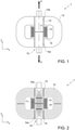
- Figure 1 shows a cross-section, in a Cartesian reference plane zx, of a first release system (denoted as a whole by 1) according to a first preferred embodiment of the present invention.
- Said first release system 1 includes a segmented tie rod 10 that extends mainly parallelly to axis z and comprises a first segment 10a and a second segment 10b, that are soldered to one another by means of a solder alloy forming a solder joint 11 between said first and second segments 10a and 10b.
- the first segment 10a can be conveniently preloaded by being either securely fixed to an external carrying structure (not shown in Figure 1 ), such as a satellite or spacecraft, or coupled to one or more preloaded extractor springs (not shown in Figure 1 ). Additionally, the second segment 10b can be conveniently preloaded by being coupled to one or more preloaded extractor springs (not shown in Figure 1 ). The preload of the first and second segments 10a and 10b results in opposite forces P exerted on said first and second segments 10a and 10b.
- the first release system 1 further includes:
- the external casing 12 and the segmented tie rod 10 can be "seen” as a magnetic circuit of a transformer.
- This magnetic circuit presents three discontinuities, wherein:
- the coil 13 is supplied by an AC generator (not shown in figure 1 ) with an AC electric signal having predefined frequency and amplitude, and thus generates a primary magnetic field.
- an AC generator not shown in figure 1
- the coil 13 i.e., the primary winding of the transformer
- a time-varying magnetic field is produced thus generating magnetic induction into the magnetic circuit.
- Figure 2 shows the same cross-section of the first release system 1 as Figure 1 , additionally illustrating flux lines of the magnetic flux generated by the coil 13.
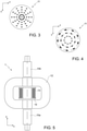
- Figures 3 and 4 show a cross-section of the solder joint 11 parallelly to axis x (namely, in a Cartesian reference plane xy orthogonal to the Cartesian reference plane zx) and illustrate, respectively, the flux lines of the magnetic flux generated by the coil 13 and eddy currents induced by said magnetic flux.
- the magnetic flux generated by the coil 13 is normal to the cross section of the solder joint 11 and induces planar eddy currents that generate a counter flux opposite to the primary flux generated by the coil 13.
- the magnetic induction is substantially constant with the thickness of the solder joint 11, since it is quite small with respect to the cross-sectional size and also to the skin depth penetration at the predefined operating frequency.
- the eddy currents induced by the magnetic flux generated by the coil 13 into the solder joint 11 can be considered as the secondary winding of the transformer.
- the solder joint is made of a high electrical conductivity alloy (for example, a silver and/or gold alloy), since ohmic losses are proportional to the material conductivity.
- the melting temperature of the solder alloy is reasonably low (in particular, conveniently comprised between 200°C and 400°C). Therefore, an eutectic alloy or an alloy with low melting temperature is preferably used. Moreover, the solder alloy is able also to guarantee the capability of the solder joint 11 to carry the preload with adequate margins.
- solder alloys preferably exploitable according to the present invention are listed in the following table, which reports also respective melting temperatures and mechanical strengths, and whether they are eutectic. TABLE Melting temperature [°C] Composition by mass [%] Eutectic Mechanical strength [MPa] 233 65.0Sn/25.0Ag/10.0Sb No 117 280 80.0Au/20.0Sn Yes 276 356 88.0Au/12.0Ge Yes 185 363 96.8Au/3.2Si Yes 255
- solder joint 11 has the function of:
- an optional joint configuration provides for a highly electrically conductive thin metallic layer or foil (preferably made of pure copper) to be used in addition to the aforesaid solder materials.
- the tie rod can conveniently include from the bottom upwards:
- the use of copper is particularly advantageous, since copper has both high electrical conductivity and high mechanical strength (for example, also silver could be used, since it has a slightly higher electrical conductivity than copper; but silver has lower mechanical strength than copper, so the latter is preferable).
- the segmented tie rod 10 and, more preferably, also the external casing 12 are made of a soft magnetic alloy in order to reduce the reluctance of the magnetic circuit and, thence, maximize the magnetic flux which generates the eddy currents in the solder joint and relevant ohmic losses.
- said soft magnetic alloy includes pure iron (such as ARMCO ® pure iron), or is a silicon-iron alloy (conveniently with 1.0-4.0% Si), or is a cobalt-iron alloy (conveniently with up to 50% Co)
- Figure 5 shows a cross-section, in the Cartesian reference plane zx, of the first release system 1 after the solder alloy forming the solder joint 11 has melted and with reference to the case in which both the first and second segments 10a and 10b of the segmented tie rod 10 are coupled to preloaded extractor springs (not shown in Figure 5 ).
- said first and second segments 10a and 10b are released and then separated from one another as a consequence of the melting of the solder alloy forming the solder joint 11 and of the pulling forces exerted by the preloaded extractor springs.
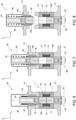
- Figures 6-8 are cross-sectional views in the Cartesian reference plane zx and illustrate an example of use of the first release system 1 in a HRM for a deployable antenna of a satellite.
- the first release system 1 is coupled to:
- the configuration involved in the example shown in Figures 6-8 is based on a toroidal magnetic circuit having the primary winding coaxial with the tie rod 10 and the axially symmetric external casing 12 all around.
- the separable conical joint 32 is structurally connected to a main shaft and extractor 33, which is spliced into a sphere of a spherical joint 34 and is bolted to the second segment 10b of the segmented tie rod 10. Moreover, the first segment 10a is preloaded by means of the preloading nut 22.
- An external casing of the spherical joint 34 is spliced into the second interface flange 31.
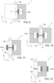
- FIGS 9-16 show further preferred embodiments of the present invention, which:
- release system according to the present invention can fully cover the preload and temperature ranges required for this kind of devices (i.e., respectively, [0N,150kN] and [-130°C, +150°C]).
- the release system according to the present invention induces only ultralow shocks, because the separation of the segments of the segmented structural element is very soft due to the fact the it is generated by a melting process, while residual shock, which is only due to preloading strain energy, can be easily managed by dedicated design at HRM level.
- the release system according to the present invention does not produce any debris, thereby meeting ESA's space debris mitigation requirements.
- the present invention overcomes any export control restriction issue, since it based on technologies fully owned by the Applicant.
- Figure 17 shows a comparison between the costs of a standard pyro-cutter and of the release system according to the present invention as a function of the number of deployable antennas for satellites produced per year (taking into consideration the use of four HRMs for each antenna).
- the present invention provides the following key features:
Landscapes
- Engineering & Computer Science (AREA)
- Mechanical Engineering (AREA)
- Combustion & Propulsion (AREA)
- Transportation (AREA)
- Chemical & Material Sciences (AREA)
- Remote Sensing (AREA)
- Aviation & Aerospace Engineering (AREA)
- General Health & Medical Sciences (AREA)
- Physics & Mathematics (AREA)
- Astronomy & Astrophysics (AREA)
- General Physics & Mathematics (AREA)
- Dermatology (AREA)
- Health & Medical Sciences (AREA)
- Fuses (AREA)
- Details Of Aerials (AREA)
- Electric Connection Of Electric Components To Printed Circuits (AREA)
- Manufacturing Of Electrical Connectors (AREA)
- Connections Effected By Soldering, Adhesion, Or Permanent Deformation (AREA)
Description
- The present invention relates to a non-explosive release actuator that finds advantageous, but non-exclusive, application for aerospace Hold-down and Release Mechanisms (HRMs). Moreover, the present invention can be advantageously exploited also for fragmentation of end-of-life space systems and for release of a space system from a launch vehicle (or launcher).
- As is known, space systems (such as satellites and spacecrafts) typically have deployable appendages (such as antennas, solar arrays, booms, supports, instruments, etc.) that are held stowed for launch in order to fit into the available launcher volume and to survive the launch mechanical environment, and that are then released and deployed in orbit for operation.
- In order to achieve these functions, Hold-down and Release Mechanisms (HRMs) are commonly used, which securely and strongly connect and hold down the deployable appendages of a space system during launch, and which release said deployable appendages upon reception of a command signal, in particular when the space system is in orbit and has reached a predefined position in outer space.
- Currently, the most extensively used HRMs are based on pyrotechnics, such as pyro-cutters, pyrotechnic nuts, pyrotechnic bolt/wire/cable cutters, etc.; for example, some of the HRMs currently used in aerospace sector exploit a pyro-cutter to cut a preloaded tie-rod.
- As is broadly known, pyrotechnic HRMs, despite their huge heritage and high reliability, present severe drawbacks. In particular, pyrotechnic HRMs produce shocks that can be extremely dangerous for integrity of delicate equipment. This shock issue can be mitigated by dedicated design at HRM level, but, nevertheless, pyrotechnic HRMs can still produce hazardous shocks. Moreover, in order to try to (further) mitigate this shock issue, relevant electronic units are generally over-tested, thereby resulting in highly expensive test campaigns. However, despite this over-testing, unit failures are still quite recurrent. Additionally, manipulation, storage and operation of pyrotechnic HRMs can be intrinsically hazardous.
- The current trend in aerospace sector is towards space systems, in particular satellites, that are smaller, lighter, more complex, more versatile and with more sensitive on-board instrumentation. The combination of all these factors leads to the need to drastically reduce shocks generated by the HRMs and, thence, to use non-explosive HRMs. In addition, the trend to move away from pyrotechnic systems is growing also due to the fact that substantial cost savings can be achieved with the avoidance of safety-related costs currently involved by the use of pyrotechnic HRMs. In this connection, it is worth also noting that in the context of the "Horizon 2020" research and innovation programme of the European Union, the European Commission (EC), European Space Agency (ESA) and European Defense Agency (EDA) have drawn up a list of urgent actions for critical space technologies for European strategic non-dependence, which includes also the need for non-explosive hold-down and release actuators intended to completely supersede the pyrotechnic ones. In particular, said non-explosive hold-down and release actuators shall meet ultralow shock requirements (<300g) that cannot be fulfilled by any pyrotechnic actuator, shall cover tightening tension and temperature ranges that are highly demanding (respectively, [0N,150kN] and [-130°C,+150°C]), and shall have a competitive price.
- Therefore, many in-depth researches have been carried out in order to develop non-explosive actuators for HRMs, such as:
- actuators based on the use of Shape Memory Alloys (SMAs), wherein said SMAs change their geometrical shape (length, angle, etc.) upon reaching their transition temperature, thereby actuating the release of a mechanical joint (for example by breaking a joining bolt, or by changing the geometry of an element maintaining a joint so as to release a fastener or a retainer, etc.); and
- actuators (such as separation/split spool devices) based on the use of fuse wires, wherein said fuse wires
- keep mechanical elements preloaded (such as fuse wires acting as locking members that fasten tensioned members, such as preloaded coil springs, keeping together split spools), and,
- when necessary, are heated up to fuse or self-destruct, thereby triggering the release mechanism (for example, a fuse wire, upon fusing or self-destructing, releases a preloaded coil spring which, in cascade, releases a split spool).
- An example of non-explosive, SMA-based HRM is provided in the paper by Vazquez J. and Bueno I. entitled "Non explosive low shock reusable 20 kN hold-down release actuator" (Proceedings of the 9th European Space Mechanisms and Tribology Symposium, 19-21 September 2001, Liege, Belgium - ESA SP-480, pages 131-135, September 2001). In particular, this paper discloses a mechanism based on a segmented nut kept in position by a preloaded mechanism, which is clamped with a latch than can be triggered by a wire of SMA.
- A further example of non-explosive, SMA-based HRM is provided also in the paper by Nava N. et al. entitled "A novel hold-down and release mechanism for non-explosive actuators based on SMA technology" (Proceedings of the 16th European Space Mechanisms and Tribology Symposium, 23-25 September 2015, Bilbao, Spain - ESA SP-737, September 2015). In particular, this paper discloses a HRM triggered by a SMA fibre that can pull with about 70N of force. Since the HRM handles high external forces (for example preloads of 35KN and pin stroke forces of 500N), the decomposition of these loads is necessary to perform the complete triggering operation. In detail, the mechanism proposed in said paper is mainly composed of:
- a trigger part, called Crown, pulled by a SMA wire for operation;
- spheres that support the mechanical interfaces (pin or rod and nut); and
- spheres for decomposing the external forces down to a force that SMA can handle.
- Instead, an example of non-explosive HRM based on the use of fuse wires is provided in
US 2012/0293294 A1 , that discloses an apparatus comprising: - a restraint release mechanism comprising one or more restraint release arms;
- a redundant release device comprising a segmented spool having a plurality of segments that are constrained from separating by spring restraint tape releasably secured to the restraint release arms;
- a redundant fuse wire assembly coupled to the redundant release device and comprising
- a primary positive contact,
- a redundant positive contact,
- a common negative contact,
- a primary fuse wire connected between the primary positive contact and the common negative contact that wraps around the redundant positive contact and the restraint release arms, and
- a redundant fuse wire connected between the redundant positive contact and the common negative contact that wraps around the primary positive contact and the restraint release arms; and
- an electrical power source coupled to the redundant fuse wire assembly for heating and severing the fuse wires.
- SMA-based HRMs suffer from severe tightening tension and temperature limitations, while split spool devices based on the use of fuse wires are subject to severe export control restrictions.
- Moreover, both said technologies suffer from reliability issues due to mechanical complexity of the relevant hold-down and release systems.
- Additionally,
WO 2015/014943 A1 andWO 2015/014942 A1 relate to a method and device for connecting and separating two elements, with connecting plates, suitable for separating stages of a launcher. In particular, the method and the device according toWO 2015/014943 A1 andWO 2015/014942 A1 enable the linear separation of two elements attached to each other, through two respective connecting surfaces of these two elements. A connecting layer is placed between both connecting parts. Thermite is used to melt this connecting layer. The thermite can be placed on the other side of the first connecting part towards the first element, a heat protecting plate completing this assembly. The thermite can also be placed in grooves provided on the connecting surface of the second connecting plate to be directly in contact with the connecting layer. - Furthermore, taking a completely different technical field into consideration (i.e., the field of gas turbine technology),
WO 2013/144035 A1 discloses a method for processing a modular hybrid component comprising a first part made of a first material and a second part made of a second material different from said first material with regard to its electromagnetic and/or thermal properties (e.g., a ceramic part and a metal part). According toWO 2013/144035 A1 , the modular hybrid component is exposed to an alternating electromagnetic field, whereby both parts are heated up differently and a brazing or soldering joint, or field sensitive mineral cement, provided between said first and second parts is affected by said heating action. In particular, the method according toWO 2013/144035 A1 allows assembling and disassembling parts made of different materials (more specifically, ceramic and metal parts). In fact, this method has been expressly conceived for replacement of worn/damaged parts of gas turbines. - Object of the present invention is that of providing a non-explosive HRM that is:
- alternative to those ones based on the use of SMAs and fuse wires so that to avoid the aforesaid relevant drawbacks;
- alternative to that one according to
WO 2015/014943 A1 so that to be more efficient and more reliable; and - such that to meet the aforesaid ultralow shock requirements (i.e., <300g), cover the aforesaid highly demanding ranges of tightening tensions and temperatures (i.e., respectively, [0N,150kN] and [-130°C,+150°C]), and have a competitive price.
- This and other objects are achieved by the present invention in that it relates to a release system for space systems, as defined in the appended claims.
- For a better understanding of the present invention, preferred embodiments, which are intended purely by way of non-limiting examples, will now be described with reference to the attached drawings (all not to scale), wherein:
-
Figures 1-5 illustrate a release system according to a first preferred embodiment of the present invention; -
Figures 6-8 illustrate an example of use of the release system according to said first preferred embodiment of the present invention in a hold-down and release mechanism for a deployable antenna of a satellite; -
Figures 9-16 illustrate further preferred embodiments of the present invention; and -
Figures 17 shows a comparison between the costs of a standard pyro-cutter and of the release system according to the present invention. - The following discussion is presented to enable a person skilled in the art to make and use the invention. Various modifications to the embodiments will be readily apparent to those skilled in the art, without departing from the scope of the present invention as claimed. Thence, the present invention is not intended to be limited to the embodiments shown and described, but is to be accorded the widest scope consistent with the principles and features disclosed herein and defined in the appended claims.
- The present invention relates to a non-explosive release system including a segmented structural element (for example, in the form of a segmented tie rod), that comprises:
- a first segment designed to be coupled to a first structure (conveniently, a satellite or a spacecraft);
- a second segment designed to be coupled to a second structure (conveniently, a deployable appendage or apparatus of said satellite/spacecraft); and
- a solder joint joining respective ends of said first and second segments, thus securely holding down the first and second structures with respect to one another; wherein said solder joint is electromagnetically heatable and includes a solder alloy (preferably an eutectic alloy) having a predefined melting temperature
- Moreover, the non-explosive release system further includes magnetic field generating means configured to, upon reception of a release command, generate a time-varying magnetic field through the solder joint such that to cause heating thereof up to the predefined melting temperature of the solder alloy, thereby causing melting of said solder alloy; whereby separation of the first and second segments is caused, thus enabling release of the first and second structures from one another.
- Conveniently, the solder alloy is a gold or silver alloy.
- Preferably, the predefined melting temperature of the solder alloy is comprised between 200°C and 400°C, and said solder alloy is characterized by a mechanical strength higher than 100 MPa.
- Preferably, the solder alloy is electromagnetically heatable, the solder joint is made up of said solder alloy, and the magnetic field generating means are configured to generate a time-varying magnetic field through the solder joint such that to induce eddy currents in said solder alloy (according to Faraday's law of induction), thereby causing heating thereof up to said predefined melting temperature.
- Alternatively, the solder joint further includes a metal (preferably copper), and the magnetic field generating means are configured to generate a time-varying magnetic field through the solder joint such that to induce eddy currents in said metal (according to Faraday's law of induction), thereby causing heating thereof; whereby the heating of said metal causes the solder alloy to heat up to its predefined melting temperature. Conveniently, the solder joint includes:
- two layers made of the solder alloy; and
- a layer that is made of said metal and is interposed between said two layers made of the solder alloy.
- Preferably, the segmented structural element extends mainly along a longitudinal axis, the solder joint has a substantially uniform cross-sectional size orthogonally to said longitudinal axis and a thickness along said longitudinal axis quite smaller than said cross-sectional size, and the magnetic field generating means are designed to generate a time-varying magnetic field extending through the solder joint substantially parallelly to said longitudinal axis.
- The present invention can be advantageously exploited to:
- hold down and release deployable appendages/apparatuses of a satellite/spacecraft (whereby the aforesaid first structure is a satellite/spacecraft and the aforesaid second structure is a deployable appendage/apparatus of said satellite/spacecraft);
- achieve fragmentation of end-of-life space systems (whereby the aforesaid first and second structures are, respectively, a first component/apparatus and a second component/apparatus of one and the same space system, such as a satellite or spacecraft or launch vehicle designed to fragment before or during re-entry into the Earth's atmosphere); and
- release a satellite or a spacecraft from a launch vehicle (whereby the aforesaid first and second structures are, respectively, a launcher and a satellite/spacecraft carried by the latter).
- For the sake of description simplicity and, thence, without losing generality, in the following preferred embodiments of the present invention will be described in detail by making explicit reference to a segmented structural element in the form of a segmented tie rod used to hold down and release deployable appendages/apparatuses of satellites/spacecrafts.
- For a better understanding of the present invention, working principle thereof can be compared to a transformer whose primary winding, supplied with an AC voltage, induces a magnetic flux into a magnetic circuit made up of the segmented tie rod and an external casing housing said segmented tie rod.
- The general equation that applies to said magnetic circuit is:

- Since the segmented tie rod comprises two segments soldered to one another with a conductive solder alloy which exhibits an effective diamagnetism when experiencing a time-varying magnetic field, the magnetic flux induces eddy currents in the solder joint according to Faraday's law of induction, which eddy currents produce ohmic losses, namely Joule heating, thus increasing the temperature of the solder alloy up to the melting temperature thereof.
- Once the melting temperature is reached, the tie rod (which is also conveniently subjected to mechanical preload and to an extractor spring force) becomes separated into two segments, thus achieving release.
- As previously explained, the use of fuse elements to achieve the separation of mechanical elements has been already exploited in the past. However, from the foregoing it is absolutely clear that the system according to the present invention is completely different from the ones currently known.
- In particular, it is worth noting that one of the (several) main differences between the present invention and the current actuators based on the use of fuse elements is due to the fact that, according to the present invention, the solder joint carries directly the preload and the external extraction forces, while in the other actuators the fuse elements do not carry directly the preload, neither the external extraction forces.
- Moreover, from a reliability point of view, the correct operation of the present invention is based on the success of only one event (i.e., the magnetically-induced melting of the solder joint), while for the split spool devices the correct operation is based on the success of at least two events and, additionally, the parts to be released are subjected to frictional relative motion.
- Furthermore, it is worth noting also that the mechanical complexity of the present invention is much lower than all the other existing non-explosive release solutions.
- For a better understanding of the present invention,
Figure 1 shows a cross-section, in a Cartesian reference plane zx, of a first release system (denoted as a whole by 1) according to a first preferred embodiment of the present invention. Saidfirst release system 1 includes asegmented tie rod 10 that extends mainly parallelly to axis z and comprises afirst segment 10a and asecond segment 10b, that are soldered to one another by means of a solder alloy forming a solder joint 11 between said first andsecond segments - The
first segment 10a can be conveniently preloaded by being either securely fixed to an external carrying structure (not shown inFigure 1 ), such as a satellite or spacecraft, or coupled to one or more preloaded extractor springs (not shown inFigure 1 ). Additionally, thesecond segment 10b can be conveniently preloaded by being coupled to one or more preloaded extractor springs (not shown inFigure 1 ). The preload of the first andsecond segments second segments - Moreover, the
first release system 1 further includes: - an
external casing 12, that is a hollow soft-magnetic casing housing thesegmented tie rod 10; and - a coil or
solenoid 13, that comprises several metal windings, such as several copper windings, and is carried by a coil carrier 14 (conveniently made of dielectric material) so as to be wound around a middle portion of thesegmented tie rod 10, which middle portion includes thesolder joint 11. - As previously explained, the
external casing 12 and thesegmented tie rod 10 can be "seen" as a magnetic circuit of a transformer. - This magnetic circuit presents three discontinuities, wherein:
- a first discontinuity is between the
first segment 10a and thesecond segment 10b of thesegmented tie rod 10, that is the solder joint 11, which is "seen" by a magnetic flux generated by thecoil 13 as a magnetic discontinuity since the solder alloy is diamagnetic (the thickness of the solder joint 11 parallelly to the axis z being quite small so that the magnetic flux can pass through it without significant dispersion); and - the other two discontinuities are
air gaps 15 present between theexternal casing 12 and, respectively, thefirst segment 10a and thesecond segment 10b of the segmented tie rod 10 (saidair gaps 15 being required for the tie rod insertion during an integration phase and for the tie rod segment(s) extraction after the release). - All the above discontinuities are the major contributors to the whole reluctance of the magnetic circuit.
- The
coil 13 is supplied by an AC generator (not shown infigure 1 ) with an AC electric signal having predefined frequency and amplitude, and thus generates a primary magnetic field. In particular, since the coil 13 (i.e., the primary winding of the transformer) is fed with an AC electric signal, a time-varying magnetic field is produced thus generating magnetic induction into the magnetic circuit. - In this respect,
Figure 2 shows the same cross-section of thefirst release system 1 asFigure 1 , additionally illustrating flux lines of the magnetic flux generated by thecoil 13. Moreover,Figures 3 and 4 show a cross-section of the solder joint 11 parallelly to axis x (namely, in a Cartesian reference plane xy orthogonal to the Cartesian reference plane zx) and illustrate, respectively, the flux lines of the magnetic flux generated by thecoil 13 and eddy currents induced by said magnetic flux. - As shown in
Figures 2-4 , the magnetic flux generated by thecoil 13 is normal to the cross section of the solder joint 11 and induces planar eddy currents that generate a counter flux opposite to the primary flux generated by thecoil 13. - The magnetic induction is substantially constant with the thickness of the solder joint 11, since it is quite small with respect to the cross-sectional size and also to the skin depth penetration at the predefined operating frequency.
- The eddy currents induced by the magnetic flux generated by the
coil 13 into the solder joint 11 can be considered as the secondary winding of the transformer. Conveniently, the solder joint is made of a high electrical conductivity alloy (for example, a silver and/or gold alloy), since ohmic losses are proportional to the material conductivity. - The melting temperature of the solder alloy is reasonably low (in particular, conveniently comprised between 200°C and 400°C). Therefore, an eutectic alloy or an alloy with low melting temperature is preferably used. Moreover, the solder alloy is able also to guarantee the capability of the solder joint 11 to carry the preload with adequate margins.
- Some solder alloys preferably exploitable according to the present invention are listed in the following table, which reports also respective melting temperatures and mechanical strengths, and whether they are eutectic.
TABLE Melting temperature [°C] Composition by mass [%] Eutectic Mechanical strength [MPa] 233 65.0Sn/25.0Ag/10.0Sb No 117 280 80.0Au/20.0Sn Yes 276 356 88.0Au/12.0Ge Yes 185 363 96.8Au/3.2Si Yes 255 - In summary, the solder joint 11 has the function of:
- providing mechanical strength;
- supporting eddy currents and generating dissipation power; and
- melting down at a given low temperature.
- Conveniently, an optional joint configuration provides for a highly electrically conductive thin metallic layer or foil (preferably made of pure copper) to be used in addition to the aforesaid solder materials. In this case, the tie rod can conveniently include from the bottom upwards:
- the lower part of the tie rod (i.e., the aforesaid
first segment 10a); - a first solder joint formed by one of the aforesaid solder alloys;
- a metal foil or layer (for example, with a thickness of 0.1-0.5 mm), preferably made of copper;
- a second solder joint formed by one of the aforesaid solder alloys; and
- the upper part of the tie rod (i.e., the aforesaid
second segment 10b). - With this alternative solution it is possible to distinguish the functions of the first and second solder joints and of the metal foil or layer as follows:
- the first and second solder joints provide mechanical strength and melt down at a given low temperature;
- the metal foil or layer supports eddy currents and generates power to heat the solder joints up to the melting thereof.
- With this optional configuration it is possible to control directly the dissipated power, since it is proportional to the square of the thickness of the metal foil or layer. In this respect, the use of copper is particularly advantageous, since copper has both high electrical conductivity and high mechanical strength (for example, also silver could be used, since it has a slightly higher electrical conductivity than copper; but silver has lower mechanical strength than copper, so the latter is preferable).
- Preferably, the
segmented tie rod 10 and, more preferably, also theexternal casing 12 are made of a soft magnetic alloy in order to reduce the reluctance of the magnetic circuit and, thence, maximize the magnetic flux which generates the eddy currents in the solder joint and relevant ohmic losses. More preferably, said soft magnetic alloy includes pure iron (such as ARMCO® pure iron), or is a silicon-iron alloy (conveniently with 1.0-4.0% Si), or is a cobalt-iron alloy (conveniently with up to 50% Co) - Furthermore,
Figure 5 shows a cross-section, in the Cartesian reference plane zx, of thefirst release system 1 after the solder alloy forming the solder joint 11 has melted and with reference to the case in which both the first andsecond segments segmented tie rod 10 are coupled to preloaded extractor springs (not shown inFigure 5 ). In particular, as shown inFigure 5 , said first andsecond segments -
Figures 6-8 are cross-sectional views in the Cartesian reference plane zx and illustrate an example of use of thefirst release system 1 in a HRM for a deployable antenna of a satellite. - In particular, in the example shown in
Figures 6-8 thefirst release system 1 is coupled to: - a satellite (not shown in
Figures 6-8 ) by means of a fixedbase assembly 20, that includes afirst interface flange 21 securely fixed to said satellite, and a preloadingnut 22 coupled to thefirst segment 10a of thesegmented tie rod 10; and - a deployable antenna (not shown in
Figures 6-8 ) by means of a deployableupper assembly 30, that- includes a
second interface flange 31 securely fixed to said deployable antenna, and - is releasably jointed to the
base structure 20 by means of separable conical joint 32.
- includes a
- The configuration involved in the example shown in
Figures 6-8 is based on a toroidal magnetic circuit having the primary winding coaxial with thetie rod 10 and the axially symmetricexternal casing 12 all around. - The separable conical joint 32 is structurally connected to a main shaft and
extractor 33, which is spliced into a sphere of a spherical joint 34 and is bolted to thesecond segment 10b of thesegmented tie rod 10. Moreover, thefirst segment 10a is preloaded by means of the preloadingnut 22. - An external casing of the spherical joint 34 is spliced into the
second interface flange 31. - With specific reference to
Figures 7 and 8 , when the solder joint 11 has melted, the main shaft andextractor 33, together with thesecond segment 10b, are pushed away, by means of anextractor spring 35, up to get in contact with aprotective cup 36 which prevents the main shaft andextractor 33 from being ejected far away. At this point, the separable conical joint 32 is no longer preloaded and, thence, the deployableupper assembly 30 can be deployed freely, while the fixedbase assembly 20 remains fixed. -
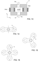
Figures 9-16 show further preferred embodiments of the present invention, which: - involve, all, the use of the
segmented tie rod 10 comprising the first andsecond segments - differ from one another in the way in which the magnetic flux is induced into said
segmented tie rod 10. - In particular, it can be noted that:
-
Figure 9 shows a cross-section, in the Cartesian reference plane zx, of the first release system 1 (also shown inFigures 1, 2 and5-8 ), which has a toroidal, axially symmetric configuration with primary winding PW1 on axis (said primary winding PW1 being denoted inFigures 1, 2 and5-8 as 13); -
Figure 10 shows a cross-section, in the Cartesian reference plane zx, of a second release system (denoted as whole by 2) according to a second preferred embodiment of the present invention, wherein saidsecond release system 2 has a planar symmetric configuration with primary winding PW2 on axis; -
Figure 11 shows a cross-section, in the Cartesian reference plane zx, of a third release system (denoted as whole by 3) according to a third preferred embodiment of the present invention, wherein saidthird release system 3 has a planar asymmetric configuration with primary winding PW3 on axis; -
Figure 12 shows a cross-section, in the Cartesian reference plane zx, of a fourth release system (denoted as whole by 4) according to a fourth preferred embodiment of the present invention, wherein saidfourth release system 4 has a planar asymmetric configuration with primary winding PW4 off axis; -
Figure 13 shows a cross-section, in the Cartesian reference plane zx, of a fifth release system (denoted as whole by 5) according to a fifth preferred embodiment of the present invention, wherein saidfifth release system 5 has a N-branch symmetric configuration with primary windings PW5 off axis; -
Figures 14, 15 and 16 show top views of three examples of use of thefifth release system 5, in particular with reference to, respectively, a 2-branch symmetric configuration with primary windings PW5 off axis, a 3-branch symmetric configuration with primary windings PW5 off axis, and a 4-branch symmetric configuration with primary windings PW5 off axis. - From the foregoing description the technical advantages of the present invention are immediately clear.
- In particular, it is important to point out that the release system according to the present invention can fully cover the preload and temperature ranges required for this kind of devices (i.e., respectively, [0N,150kN] and [-130°C, +150°C]).
- Moreover, the release system according to the present invention induces only ultralow shocks, because the separation of the segments of the segmented structural element is very soft due to the fact the it is generated by a melting process, while residual shock, which is only due to preloading strain energy, can be easily managed by dedicated design at HRM level.
- Additionally, the release system according to the present invention does not produce any debris, thereby meeting ESA's space debris mitigation requirements.
- Furthermore, the present invention overcomes any export control restriction issue, since it based on technologies fully owned by the Applicant.
- Besides the above advantages, it is worth noting also that the release system according to the present invention allows to achieve a remarkable cost saving with respect to pyrotechnic actuators. In this respect,
Figure 17 shows a comparison between the costs of a standard pyro-cutter and of the release system according to the present invention as a function of the number of deployable antennas for satellites produced per year (taking into consideration the use of four HRMs for each antenna). - To sum up, the present invention provides the following key features:
- non-explosive;
- almost zero shock;
- very high preload;
- wide operating temperature ranges;
- mechanically simple;
- low mass;
- unlimited shelf and in-orbit life;
- low cost;
- no debris;
- no export control restrictions;
- resettable by tie rod replacing as well as for the current HRMs.
- Finally, it is important to stress again the point that the present invention, in addition to HRM applications, can be advantageously exploited also to:
- achieve fragmentation of end-of-life space systems to meet space debris control regulations; and
- restrain during launch and then release in orbit a satellite or spacecraft carried by a launch vehicle (for example from the launcher upper stage in place of the standard Marman clamp).
- In conclusion, it is clear that numerous modifications and variants can be made to the present invention, all falling within the scope of the invention, as defined in the appended claims.
Claims (16)
- Release system (1,2,3,4,5) configured for space systems, including a segmented structural element (10) that comprises a first segment (10a) configured to be coupled to a first structure and a second segment (10b) configured to be coupled to a second structure, wherein said first and second structures are respectively:• a satellite/spacecraft and a deployable appendage/apparatus of said satellite/spacecraft; or• a launch vehicle and a satellite/spacecraft to be launched by said launch vehicle; or• a first component/apparatus and a second component/apparatus of a satellite/spacecraft/launch vehicle designed to fragment before or during re-entry into the Earth's atmosphere;wherein the segmented structural element (10) further comprises a solder joint (11) joining respective ends of said first (10a) and second (10b) segments, thus holding down the first and second structures with respect to one another; wherein said solder joint (11) is electromagnetically heatable and includes a solder alloy having a predefined melting temperature;characterized by further including magnetic field generating means (13;PW1;PW2;PW3;PW4;PW5;PW5a;PW5b;PW5c) configured to, upon reception of a release command, generate a time-varying magnetic field through the solder joint (11) such that to cause heating thereof up to the predefined melting temperature of the solder alloy, thereby causing melting of said solder alloy; whereby separation of the first (10a) and second (10b) segments is caused, thus enabling release of the first and second structures from one another.
- The release system of claim 1, wherein the solder alloy is an eutectic alloy.
- The release system according to claim 1 or 2, wherein the solder alloy is electromagnetically heatable; wherein the solder joint (11) is made up of said solder alloy; and wherein the magnetic field generating means (13,PW1,PW2,PW3,PW4,PW5) are configured to generate a time-varying magnetic field through the solder joint (11) such that to induce eddy currents in said solder alloy, thereby causing heating thereof up to said predefined melting temperature.
- The release system according to claim 1 or 2, wherein the solder joint (11) further includes a metal; and wherein the magnetic field generating means (13,PW1,PW2,PW3,PW4,PW5) are configured to generate a time-varying magnetic field through the solder joint (11) such that to induce eddy currents in said metal, thereby causing heating thereof; whereby the heating of said metal causes the solder alloy to heat up to its predefined melting temperature.
- The release system of claim 4, wherein the solder joint (11) includes:• two layers made of the solder alloy; and• a layer that is made of said metal and is interposed between said two layers made of the solder alloy.
- The release system according to claim 4 or 5, wherein said metal is copper.
- The release system according to any preceding claim, wherein the solder alloy is a gold or silver alloy.
- The release system according to any preceding claim, wherein the predefined melting temperature is comprised between 200°C and 400°C.
- The release system according to any preceding claim, wherein the solder alloy is characterized by a mechanical strength higher than 100 MPa.
- The release system according to any preceding claim, wherein the segmented structural element (10) is made of a soft magnetic alloy.
- The release system according to any preceding claim, further including a soft-magnetic casing (12) housing the segmented structural element (10).
- The release system according to any preceding claim, wherein the magnetic field generating means include a coil (13,PW1,PW2,PW3,PW4,PW5) connected to a an alternating current generator to be supplied thereby.
- Space system equipped with the release system (1,2,3,4,5) as claimed in any preceding claim.
- The space system of claim 13, wherein said space system is a satellite or a spacecraft equipped with a deployable appendage or apparatus; and wherein said first (10a) and second (10b) segments of the segmented structural element (10) of the release system (1,2,3,4,5) are coupled to, respectively, said satellite/spacecraft and said deployable appendage/apparatus.
- The space system of claim 13, wherein said space system is a launch vehicle designed to carry a satellite or a spacecraft; and wherein said first (10a) and second (10b) segments of the segmented structural element (10) of the release system (1,2,3,4,5) are coupled to, respectively, said launch vehicle and said satellite/spacecraft.
- The space system of claim 13, wherein said space system is a satellite or spacecraft or launch vehicle designed to fragment before or during re-entry into the Earth's atmosphere; and wherein said first (10a) and second (10b) segments of the segmented structural element (10) of the release system (1,2,3,4,5) are coupled to, respectively, a first component/apparatus and a second component/apparatus of said satellite/spacecraft/launch vehicle.
Applications Claiming Priority (2)
| Application Number | Priority Date | Filing Date | Title |
|---|---|---|---|
| ITUB2016A000356A ITUB20160356A1 (en) | 2016-01-15 | 2016-01-15 | NON-EXPLOSIVE RELEASE MECHANISM BASED ON FUSION WITH ELECTROMAGNETIC INDUCTION |
| PCT/EP2016/082947 WO2017121629A1 (en) | 2015-05-08 | 2016-12-30 | Non-explosive release mechanism based on electromagnetic induction melting |
Publications (2)
| Publication Number | Publication Date |
|---|---|
| EP3402624A1 EP3402624A1 (en) | 2018-11-21 |
| EP3402624B1 true EP3402624B1 (en) | 2022-03-02 |
Family
ID=55642798
Family Applications (1)
| Application Number | Title | Priority Date | Filing Date |
|---|---|---|---|
| EP16828957.7A Active EP3402624B1 (en) | 2016-01-15 | 2016-12-30 | Non-explosive release mechanism based on electromagnetic induction melting |
Country Status (5)
| Country | Link |
|---|---|
| US (1) | US11505339B2 (en) |
| EP (1) | EP3402624B1 (en) |
| JP (1) | JP2019509895A (en) |
| ES (1) | ES2914432T3 (en) |
| IT (1) | ITUB20160356A1 (en) |
Families Citing this family (4)
| Publication number | Priority date | Publication date | Assignee | Title |
|---|---|---|---|---|
| ITUB20160356A1 (en) * | 2016-01-15 | 2017-07-15 | Thales Alenia Space Italia Spa Con Unico Socio | NON-EXPLOSIVE RELEASE MECHANISM BASED ON FUSION WITH ELECTROMAGNETIC INDUCTION |
| US20250353103A1 (en) * | 2019-08-07 | 2025-11-20 | Osaka University | Dissimilar material solid phase bonding method, and dissimilar material solid phase bonded structure |
| EP4361047B1 (en) * | 2022-10-31 | 2024-12-04 | Airbus Defence and Space GmbH | Two-part passive separation mechanism for separation of two spacecraft components during the atmospheric re-entry of the spacecraft |
| FR3154383B1 (en) * | 2023-10-20 | 2025-10-10 | Airbus Defence & Space Sas | Device for retaining and releasing an on-board system relative to a spacecraft |
Family Cites Families (13)
| Publication number | Priority date | Publication date | Assignee | Title |
|---|---|---|---|---|
| WO1984002098A1 (en) | 1982-12-01 | 1984-06-07 | Metcal Inc | Connector containing fusible material and having intrinsic temperature control |
| US5093545A (en) * | 1988-09-09 | 1992-03-03 | Metcal, Inc. | Method, system and composition for soldering by induction heating |
| US7024897B2 (en) * | 1999-09-24 | 2006-04-11 | Hot Metal Gas Forming Intellectual Property, Inc. | Method of forming a tubular blank into a structural component and die therefor |
| FR2824009B1 (en) | 2001-04-27 | 2003-08-29 | Pmb | ALUMINUM-BASED SOLDERING ALLOY FOR BRAZING ALUMINUM PARTS, PARTS ASSEMBLED BY SUCH AN ALLOY, AND METHOD FOR IMPLEMENTING SUCH AN ALLOY |
| US6528771B1 (en) * | 2002-03-08 | 2003-03-04 | The Boeing Company | System and method for controlling an induction heating process |
| US7621437B2 (en) * | 2005-02-16 | 2009-11-24 | The Boeing Company | Brazed structural assembly and associated system and method for manufacture |
| US8387501B2 (en) | 2009-04-10 | 2013-03-05 | Bae Systems Information And Electronic Systems Integration Inc. | Method and apparatus for rapid severance of a decoy towline |
| AT510701B1 (en) * | 2010-12-10 | 2012-06-15 | Ruag Space Gmbh | DEVICE FOR HOLDING AND COMMANDED RELEASING A RELEASE ELEMENT OF A SPACE VEHICLE |
| WO2013144035A1 (en) | 2012-03-28 | 2013-10-03 | Alstom Technology Ltd | Method for processing a modular hybrid component |
| US8987130B2 (en) * | 2012-05-29 | 2015-03-24 | International Business Machines Corporation | Reactive bonding of a flip chip package |
| FR3009282B1 (en) | 2013-08-01 | 2017-06-09 | Astrium Sas | METHOD AND DEVICE FOR LINKING AND LINEAR SEPARATING TWO ELEMENTS WITH DECAL ENERGY MEANS |
| FR3009283B1 (en) * | 2013-08-01 | 2017-06-09 | Astrium Sas | METHOD AND DEVICE FOR BONDING AND SEPARATING TWO ELEMENTS WITH BINDING PLATES |
| ITUB20160356A1 (en) * | 2016-01-15 | 2017-07-15 | Thales Alenia Space Italia Spa Con Unico Socio | NON-EXPLOSIVE RELEASE MECHANISM BASED ON FUSION WITH ELECTROMAGNETIC INDUCTION |
-
2016
- 2016-01-15 IT ITUB2016A000356A patent/ITUB20160356A1/en unknown
- 2016-12-30 ES ES16828957T patent/ES2914432T3/en active Active
- 2016-12-30 JP JP2018536761A patent/JP2019509895A/en active Pending
- 2016-12-30 US US16/069,832 patent/US11505339B2/en active Active
- 2016-12-30 EP EP16828957.7A patent/EP3402624B1/en active Active
Also Published As
| Publication number | Publication date |
|---|---|
| ES2914432T3 (en) | 2022-06-10 |
| ITUB20160356A1 (en) | 2017-07-15 |
| EP3402624A1 (en) | 2018-11-21 |
| US20190031374A1 (en) | 2019-01-31 |
| JP2019509895A (en) | 2019-04-11 |
| US11505339B2 (en) | 2022-11-22 |
Similar Documents
| Publication | Publication Date | Title |
|---|---|---|
| EP3402624B1 (en) | Non-explosive release mechanism based on electromagnetic induction melting | |
| US20110234362A1 (en) | Shape memory circuit breakers | |
| JP6745590B2 (en) | Nanosat's electrothermal expansion system | |
| JP6473153B2 (en) | Method and apparatus for joining and separating two elements having a joining plate | |
| WO2017121629A1 (en) | Non-explosive release mechanism based on electromagnetic induction melting | |
| US9180982B2 (en) | Preload releasing fastener and release system using same | |
| US8418455B2 (en) | Shape memory alloy separating apparatuses | |
| US11378362B2 (en) | Counter UAV drone system using electromagnetic pulse | |
| US8789366B2 (en) | Shape memory stored energy assemblies and methods for using the same | |
| EP1739016B1 (en) | Method and device for magnetic space radiation shield providing isotropic protection | |
| JP2016529152A (en) | Method and apparatus for linear combination and separation of two elements with offset energy means | |
| EP0365669B1 (en) | Reverse slapper detonator | |
| EP3085627B1 (en) | Satellite comprising a separation mechanism for separation of a first satellite component from a second satellite component | |
| US20040232847A1 (en) | Electromagnetic pulse device | |
| US6439122B1 (en) | Separation system for missile payload fairings | |
| Jarvis | Golden Ratio Entropic Gravity: Gravitational Singularity Field Testing | |
| US11097372B2 (en) | Vaporizing foil actuator configured as consumable tape | |
| Dong et al. | A surface-shunting method for the prevention of a fault-mode-induced quench in high-field no-insulation REBCO magnets | |
| Hwang et al. | A compact non-explosive separation device for high preload and low shock | |
| Park et al. | Experimental Investigation on the Feasibility of Using Spring‐Loaded Pogo Pin as a Holding and Release Mechanism for CubeSat’s Deployable Solar Panels | |
| US11225340B2 (en) | Local connection device with controlled separation comprising a multidirectional bonding layer | |
| US10297376B2 (en) | Bi-stable pin actuator | |
| US10184766B2 (en) | Method and device for connecting and separating two elements, with combined connecting and separating means | |
| EP4559819B1 (en) | Bolt release system for spacecraft and launcher separation systems and separation system comprising same | |
| US20240117795A1 (en) | Integrated planar sma device and method |
Legal Events
| Date | Code | Title | Description |
|---|---|---|---|
| STAA | Information on the status of an ep patent application or granted ep patent |
Free format text: STATUS: UNKNOWN |
|
| STAA | Information on the status of an ep patent application or granted ep patent |
Free format text: STATUS: THE INTERNATIONAL PUBLICATION HAS BEEN MADE |
|
| PUAI | Public reference made under article 153(3) epc to a published international application that has entered the european phase |
Free format text: ORIGINAL CODE: 0009012 |
|
| STAA | Information on the status of an ep patent application or granted ep patent |
Free format text: STATUS: REQUEST FOR EXAMINATION WAS MADE |
|
| 17P | Request for examination filed |
Effective date: 20180706 |
|
| AK | Designated contracting states |
Kind code of ref document: A1 Designated state(s): AL AT BE BG CH CY CZ DE DK EE ES FI FR GB GR HR HU IE IS IT LI LT LU LV MC MK MT NL NO PL PT RO RS SE SI SK SM TR |
|
| AX | Request for extension of the european patent |
Extension state: BA ME |
|
| DAV | Request for validation of the european patent (deleted) | ||
| DAX | Request for extension of the european patent (deleted) | ||
| REG | Reference to a national code |
Ref country code: DE Ref legal event code: R079 Ref document number: 602016069678 Country of ref document: DE Free format text: PREVIOUS MAIN CLASS: B23K0001002000 Ipc: B62D0021060000 |
|
| GRAP | Despatch of communication of intention to grant a patent |
Free format text: ORIGINAL CODE: EPIDOSNIGR1 |
|
| STAA | Information on the status of an ep patent application or granted ep patent |
Free format text: STATUS: GRANT OF PATENT IS INTENDED |
|
| RIC1 | Information provided on ipc code assigned before grant |
Ipc: B64G 1/64 20060101ALI20210827BHEP Ipc: B23K 1/002 20060101ALI20210827BHEP Ipc: B62D 33/06 20060101ALI20210827BHEP Ipc: B62D 21/06 20060101AFI20210827BHEP |
|
| INTG | Intention to grant announced |
Effective date: 20210929 |
|
| RIN1 | Information on inventor provided before grant (corrected) |
Inventor name: MESCHINI, ALBERTO |
|
| GRAS | Grant fee paid |
Free format text: ORIGINAL CODE: EPIDOSNIGR3 |
|
| GRAA | (expected) grant |
Free format text: ORIGINAL CODE: 0009210 |
|
| STAA | Information on the status of an ep patent application or granted ep patent |
Free format text: STATUS: THE PATENT HAS BEEN GRANTED |
|
| AK | Designated contracting states |
Kind code of ref document: B1 Designated state(s): AL AT BE BG CH CY CZ DE DK EE ES FI FR GB GR HR HU IE IS IT LI LT LU LV MC MK MT NL NO PL PT RO RS SE SI SK SM TR |
|
| REG | Reference to a national code |
Ref country code: GB Ref legal event code: FG4D |
|
| REG | Reference to a national code |
Ref country code: CH Ref legal event code: EP Ref country code: AT Ref legal event code: REF Ref document number: 1472030 Country of ref document: AT Kind code of ref document: T Effective date: 20220315 |
|
| REG | Reference to a national code |
Ref country code: DE Ref legal event code: R096 Ref document number: 602016069678 Country of ref document: DE |
|
| REG | Reference to a national code |
Ref country code: IE Ref legal event code: FG4D |
|
| REG | Reference to a national code |
Ref country code: NL Ref legal event code: FP |
|
| REG | Reference to a national code |
Ref country code: ES Ref legal event code: FG2A Ref document number: 2914432 Country of ref document: ES Kind code of ref document: T3 Effective date: 20220610 |
|
| REG | Reference to a national code |
Ref country code: LT Ref legal event code: MG9D |
|
| PG25 | Lapsed in a contracting state [announced via postgrant information from national office to epo] |
Ref country code: SE Free format text: LAPSE BECAUSE OF FAILURE TO SUBMIT A TRANSLATION OF THE DESCRIPTION OR TO PAY THE FEE WITHIN THE PRESCRIBED TIME-LIMIT Effective date: 20220302 Ref country code: RS Free format text: LAPSE BECAUSE OF FAILURE TO SUBMIT A TRANSLATION OF THE DESCRIPTION OR TO PAY THE FEE WITHIN THE PRESCRIBED TIME-LIMIT Effective date: 20220302 Ref country code: NO Free format text: LAPSE BECAUSE OF FAILURE TO SUBMIT A TRANSLATION OF THE DESCRIPTION OR TO PAY THE FEE WITHIN THE PRESCRIBED TIME-LIMIT Effective date: 20220602 Ref country code: LT Free format text: LAPSE BECAUSE OF FAILURE TO SUBMIT A TRANSLATION OF THE DESCRIPTION OR TO PAY THE FEE WITHIN THE PRESCRIBED TIME-LIMIT Effective date: 20220302 Ref country code: HR Free format text: LAPSE BECAUSE OF FAILURE TO SUBMIT A TRANSLATION OF THE DESCRIPTION OR TO PAY THE FEE WITHIN THE PRESCRIBED TIME-LIMIT Effective date: 20220302 Ref country code: BG Free format text: LAPSE BECAUSE OF FAILURE TO SUBMIT A TRANSLATION OF THE DESCRIPTION OR TO PAY THE FEE WITHIN THE PRESCRIBED TIME-LIMIT Effective date: 20220602 |
|
| PG25 | Lapsed in a contracting state [announced via postgrant information from national office to epo] |
Ref country code: PL Free format text: LAPSE BECAUSE OF FAILURE TO SUBMIT A TRANSLATION OF THE DESCRIPTION OR TO PAY THE FEE WITHIN THE PRESCRIBED TIME-LIMIT Effective date: 20220302 Ref country code: LV Free format text: LAPSE BECAUSE OF FAILURE TO SUBMIT A TRANSLATION OF THE DESCRIPTION OR TO PAY THE FEE WITHIN THE PRESCRIBED TIME-LIMIT Effective date: 20220302 Ref country code: GR Free format text: LAPSE BECAUSE OF FAILURE TO SUBMIT A TRANSLATION OF THE DESCRIPTION OR TO PAY THE FEE WITHIN THE PRESCRIBED TIME-LIMIT Effective date: 20220603 Ref country code: FI Free format text: LAPSE BECAUSE OF FAILURE TO SUBMIT A TRANSLATION OF THE DESCRIPTION OR TO PAY THE FEE WITHIN THE PRESCRIBED TIME-LIMIT Effective date: 20220302 |
|
| PG25 | Lapsed in a contracting state [announced via postgrant information from national office to epo] |
Ref country code: SM Free format text: LAPSE BECAUSE OF FAILURE TO SUBMIT A TRANSLATION OF THE DESCRIPTION OR TO PAY THE FEE WITHIN THE PRESCRIBED TIME-LIMIT Effective date: 20220302 Ref country code: SK Free format text: LAPSE BECAUSE OF FAILURE TO SUBMIT A TRANSLATION OF THE DESCRIPTION OR TO PAY THE FEE WITHIN THE PRESCRIBED TIME-LIMIT Effective date: 20220302 Ref country code: RO Free format text: LAPSE BECAUSE OF FAILURE TO SUBMIT A TRANSLATION OF THE DESCRIPTION OR TO PAY THE FEE WITHIN THE PRESCRIBED TIME-LIMIT Effective date: 20220302 Ref country code: PT Free format text: LAPSE BECAUSE OF FAILURE TO SUBMIT A TRANSLATION OF THE DESCRIPTION OR TO PAY THE FEE WITHIN THE PRESCRIBED TIME-LIMIT Effective date: 20220704 Ref country code: EE Free format text: LAPSE BECAUSE OF FAILURE TO SUBMIT A TRANSLATION OF THE DESCRIPTION OR TO PAY THE FEE WITHIN THE PRESCRIBED TIME-LIMIT Effective date: 20220302 Ref country code: CZ Free format text: LAPSE BECAUSE OF FAILURE TO SUBMIT A TRANSLATION OF THE DESCRIPTION OR TO PAY THE FEE WITHIN THE PRESCRIBED TIME-LIMIT Effective date: 20220302 |
|
| PG25 | Lapsed in a contracting state [announced via postgrant information from national office to epo] |
Ref country code: IS Free format text: LAPSE BECAUSE OF FAILURE TO SUBMIT A TRANSLATION OF THE DESCRIPTION OR TO PAY THE FEE WITHIN THE PRESCRIBED TIME-LIMIT Effective date: 20220702 Ref country code: AL Free format text: LAPSE BECAUSE OF FAILURE TO SUBMIT A TRANSLATION OF THE DESCRIPTION OR TO PAY THE FEE WITHIN THE PRESCRIBED TIME-LIMIT Effective date: 20220302 |
|
| REG | Reference to a national code |
Ref country code: DE Ref legal event code: R097 Ref document number: 602016069678 Country of ref document: DE |
|
| PLBE | No opposition filed within time limit |
Free format text: ORIGINAL CODE: 0009261 |
|
| STAA | Information on the status of an ep patent application or granted ep patent |
Free format text: STATUS: NO OPPOSITION FILED WITHIN TIME LIMIT |
|
| PG25 | Lapsed in a contracting state [announced via postgrant information from national office to epo] |
Ref country code: DK Free format text: LAPSE BECAUSE OF FAILURE TO SUBMIT A TRANSLATION OF THE DESCRIPTION OR TO PAY THE FEE WITHIN THE PRESCRIBED TIME-LIMIT Effective date: 20220302 |
|
| 26N | No opposition filed |
Effective date: 20221205 |
|
| PG25 | Lapsed in a contracting state [announced via postgrant information from national office to epo] |
Ref country code: SI Free format text: LAPSE BECAUSE OF FAILURE TO SUBMIT A TRANSLATION OF THE DESCRIPTION OR TO PAY THE FEE WITHIN THE PRESCRIBED TIME-LIMIT Effective date: 20220302 |
|
| P01 | Opt-out of the competence of the unified patent court (upc) registered |
Effective date: 20230518 |
|
| REG | Reference to a national code |
Ref country code: CH Ref legal event code: PL |
|
| REG | Reference to a national code |
Ref country code: BE Ref legal event code: MM Effective date: 20221231 |
|
| PG25 | Lapsed in a contracting state [announced via postgrant information from national office to epo] |
Ref country code: LU Free format text: LAPSE BECAUSE OF NON-PAYMENT OF DUE FEES Effective date: 20221230 |
|
| PG25 | Lapsed in a contracting state [announced via postgrant information from national office to epo] |
Ref country code: LI Free format text: LAPSE BECAUSE OF NON-PAYMENT OF DUE FEES Effective date: 20221231 Ref country code: IE Free format text: LAPSE BECAUSE OF NON-PAYMENT OF DUE FEES Effective date: 20221230 Ref country code: CH Free format text: LAPSE BECAUSE OF NON-PAYMENT OF DUE FEES Effective date: 20221231 |
|
| PG25 | Lapsed in a contracting state [announced via postgrant information from national office to epo] |
Ref country code: BE Free format text: LAPSE BECAUSE OF NON-PAYMENT OF DUE FEES Effective date: 20221231 |
|
| REG | Reference to a national code |
Ref country code: AT Ref legal event code: UEP Ref document number: 1472030 Country of ref document: AT Kind code of ref document: T Effective date: 20220302 |
|
| REG | Reference to a national code |
Ref country code: ES Ref legal event code: FD2A Effective date: 20240202 |
|
| REG | Reference to a national code |
Ref country code: AT Ref legal event code: MM01 Ref document number: 1472030 Country of ref document: AT Kind code of ref document: T Effective date: 20221230 |
|
| PG25 | Lapsed in a contracting state [announced via postgrant information from national office to epo] |
Ref country code: HU Free format text: LAPSE BECAUSE OF FAILURE TO SUBMIT A TRANSLATION OF THE DESCRIPTION OR TO PAY THE FEE WITHIN THE PRESCRIBED TIME-LIMIT; INVALID AB INITIO Effective date: 20161230 |
|
| PG25 | Lapsed in a contracting state [announced via postgrant information from national office to epo] |
Ref country code: ES Free format text: LAPSE BECAUSE OF NON-PAYMENT OF DUE FEES Effective date: 20221231 |
|
| PG25 | Lapsed in a contracting state [announced via postgrant information from national office to epo] |
Ref country code: AT Free format text: LAPSE BECAUSE OF NON-PAYMENT OF DUE FEES Effective date: 20221230 |
|
| PG25 | Lapsed in a contracting state [announced via postgrant information from national office to epo] |
Ref country code: ES Free format text: LAPSE BECAUSE OF NON-PAYMENT OF DUE FEES Effective date: 20221231 Ref country code: CY Free format text: LAPSE BECAUSE OF FAILURE TO SUBMIT A TRANSLATION OF THE DESCRIPTION OR TO PAY THE FEE WITHIN THE PRESCRIBED TIME-LIMIT Effective date: 20220302 Ref country code: AT Free format text: LAPSE BECAUSE OF NON-PAYMENT OF DUE FEES Effective date: 20221230 |
|
| PG25 | Lapsed in a contracting state [announced via postgrant information from national office to epo] |
Ref country code: MK Free format text: LAPSE BECAUSE OF FAILURE TO SUBMIT A TRANSLATION OF THE DESCRIPTION OR TO PAY THE FEE WITHIN THE PRESCRIBED TIME-LIMIT Effective date: 20220302 |
|
| PG25 | Lapsed in a contracting state [announced via postgrant information from national office to epo] |
Ref country code: MC Free format text: LAPSE BECAUSE OF FAILURE TO SUBMIT A TRANSLATION OF THE DESCRIPTION OR TO PAY THE FEE WITHIN THE PRESCRIBED TIME-LIMIT Effective date: 20220302 |
|
| PG25 | Lapsed in a contracting state [announced via postgrant information from national office to epo] |
Ref country code: TR Free format text: LAPSE BECAUSE OF FAILURE TO SUBMIT A TRANSLATION OF THE DESCRIPTION OR TO PAY THE FEE WITHIN THE PRESCRIBED TIME-LIMIT Effective date: 20220302 Ref country code: MC Free format text: LAPSE BECAUSE OF FAILURE TO SUBMIT A TRANSLATION OF THE DESCRIPTION OR TO PAY THE FEE WITHIN THE PRESCRIBED TIME-LIMIT Effective date: 20220302 |
|
| PG25 | Lapsed in a contracting state [announced via postgrant information from national office to epo] |
Ref country code: MT Free format text: LAPSE BECAUSE OF FAILURE TO SUBMIT A TRANSLATION OF THE DESCRIPTION OR TO PAY THE FEE WITHIN THE PRESCRIBED TIME-LIMIT Effective date: 20220302 |
|
| PGFP | Annual fee paid to national office [announced via postgrant information from national office to epo] |
Ref country code: NL Payment date: 20241224 Year of fee payment: 9 |
|
| PGFP | Annual fee paid to national office [announced via postgrant information from national office to epo] |
Ref country code: GB Payment date: 20241217 Year of fee payment: 9 |
|
| PGFP | Annual fee paid to national office [announced via postgrant information from national office to epo] |
Ref country code: IT Payment date: 20251117 Year of fee payment: 10 |
|
| PGFP | Annual fee paid to national office [announced via postgrant information from national office to epo] |
Ref country code: FR Payment date: 20251223 Year of fee payment: 10 |
|
| PGFP | Annual fee paid to national office [announced via postgrant information from national office to epo] |
Ref country code: DE Payment date: 20251229 Year of fee payment: 10 |