EP3402564B1 - Impedance monitoring during electrostimulation - Google Patents
Impedance monitoring during electrostimulation Download PDFInfo
- Publication number
- EP3402564B1 EP3402564B1 EP17702959.2A EP17702959A EP3402564B1 EP 3402564 B1 EP3402564 B1 EP 3402564B1 EP 17702959 A EP17702959 A EP 17702959A EP 3402564 B1 EP3402564 B1 EP 3402564B1
- Authority
- EP
- European Patent Office
- Prior art keywords
- circuitry
- stimulation
- electrodes
- intraprocedural
- pass
- Prior art date
- Legal status (The legal status is an assumption and is not a legal conclusion. Google has not performed a legal analysis and makes no representation as to the accuracy of the status listed.)
- Active
Links
- 238000012544 monitoring process Methods 0.000 title description 5
- 230000000638 stimulation Effects 0.000 claims description 157
- 238000000034 method Methods 0.000 claims description 78
- 230000004936 stimulating effect Effects 0.000 claims description 73
- 230000004044 response Effects 0.000 claims description 28
- 230000001105 regulatory effect Effects 0.000 description 11
- 230000008878 coupling Effects 0.000 description 10
- 238000010168 coupling process Methods 0.000 description 10
- 238000005859 coupling reaction Methods 0.000 description 10
- 238000005259 measurement Methods 0.000 description 7
- 238000010586 diagram Methods 0.000 description 5
- 238000001827 electrotherapy Methods 0.000 description 3
- 238000002847 impedance measurement Methods 0.000 description 3
- 210000005036 nerve Anatomy 0.000 description 3
- 238000001208 nuclear magnetic resonance pulse sequence Methods 0.000 description 3
- 239000000853 adhesive Substances 0.000 description 2
- 230000001070 adhesive effect Effects 0.000 description 2
- 230000008859 change Effects 0.000 description 2
- 230000001276 controlling effect Effects 0.000 description 2
- 238000001514 detection method Methods 0.000 description 2
- 239000000463 material Substances 0.000 description 2
- 210000003205 muscle Anatomy 0.000 description 2
- 210000004165 myocardium Anatomy 0.000 description 2
- 238000012545 processing Methods 0.000 description 2
- 238000007674 radiofrequency ablation Methods 0.000 description 2
- 210000001519 tissue Anatomy 0.000 description 2
- 238000002646 transcutaneous electrical nerve stimulation Methods 0.000 description 2
- 230000001594 aberrant effect Effects 0.000 description 1
- 238000002679 ablation Methods 0.000 description 1
- 230000009471 action Effects 0.000 description 1
- 210000000577 adipose tissue Anatomy 0.000 description 1
- 210000005242 cardiac chamber Anatomy 0.000 description 1
- 230000015556 catabolic process Effects 0.000 description 1
- 238000004590 computer program Methods 0.000 description 1
- 238000006731 degradation reaction Methods 0.000 description 1
- 230000000694 effects Effects 0.000 description 1
- 238000005516 engineering process Methods 0.000 description 1
- 230000006870 function Effects 0.000 description 1
- 238000002955 isolation Methods 0.000 description 1
- 230000003902 lesion Effects 0.000 description 1
- 238000012986 modification Methods 0.000 description 1
- 230000004048 modification Effects 0.000 description 1
- 230000004118 muscle contraction Effects 0.000 description 1
- 230000002232 neuromuscular Effects 0.000 description 1
- 230000003287 optical effect Effects 0.000 description 1
- 230000037361 pathway Effects 0.000 description 1
- 238000009877 rendering Methods 0.000 description 1
- 230000035900 sweating Effects 0.000 description 1
- 230000001225 therapeutic effect Effects 0.000 description 1
Images
Classifications
-
- A—HUMAN NECESSITIES
- A61—MEDICAL OR VETERINARY SCIENCE; HYGIENE
- A61B—DIAGNOSIS; SURGERY; IDENTIFICATION
- A61B5/00—Measuring for diagnostic purposes; Identification of persons
- A61B5/05—Detecting, measuring or recording for diagnosis by means of electric currents or magnetic fields; Measuring using microwaves or radio waves
- A61B5/053—Measuring electrical impedance or conductance of a portion of the body
- A61B5/0531—Measuring skin impedance
-
- A—HUMAN NECESSITIES
- A61—MEDICAL OR VETERINARY SCIENCE; HYGIENE
- A61B—DIAGNOSIS; SURGERY; IDENTIFICATION
- A61B5/00—Measuring for diagnostic purposes; Identification of persons
- A61B5/48—Other medical applications
- A61B5/4836—Diagnosis combined with treatment in closed-loop systems or methods
-
- A—HUMAN NECESSITIES
- A61—MEDICAL OR VETERINARY SCIENCE; HYGIENE
- A61B—DIAGNOSIS; SURGERY; IDENTIFICATION
- A61B5/00—Measuring for diagnostic purposes; Identification of persons
- A61B5/68—Arrangements of detecting, measuring or recording means, e.g. sensors, in relation to patient
- A61B5/6801—Arrangements of detecting, measuring or recording means, e.g. sensors, in relation to patient specially adapted to be attached to or worn on the body surface
- A61B5/6843—Monitoring or controlling sensor contact pressure
-
- A—HUMAN NECESSITIES
- A61—MEDICAL OR VETERINARY SCIENCE; HYGIENE
- A61N—ELECTROTHERAPY; MAGNETOTHERAPY; RADIATION THERAPY; ULTRASOUND THERAPY
- A61N1/00—Electrotherapy; Circuits therefor
- A61N1/02—Details
- A61N1/04—Electrodes
- A61N1/0404—Electrodes for external use
- A61N1/0408—Use-related aspects
- A61N1/0452—Specially adapted for transcutaneous muscle stimulation [TMS]
-
- A—HUMAN NECESSITIES
- A61—MEDICAL OR VETERINARY SCIENCE; HYGIENE
- A61N—ELECTROTHERAPY; MAGNETOTHERAPY; RADIATION THERAPY; ULTRASOUND THERAPY
- A61N1/00—Electrotherapy; Circuits therefor
- A61N1/02—Details
- A61N1/04—Electrodes
- A61N1/0404—Electrodes for external use
- A61N1/0408—Use-related aspects
- A61N1/0456—Specially adapted for transcutaneous electrical nerve stimulation [TENS]
-
- A—HUMAN NECESSITIES
- A61—MEDICAL OR VETERINARY SCIENCE; HYGIENE
- A61N—ELECTROTHERAPY; MAGNETOTHERAPY; RADIATION THERAPY; ULTRASOUND THERAPY
- A61N1/00—Electrotherapy; Circuits therefor
- A61N1/18—Applying electric currents by contact electrodes
- A61N1/32—Applying electric currents by contact electrodes alternating or intermittent currents
- A61N1/36—Applying electric currents by contact electrodes alternating or intermittent currents for stimulation
- A61N1/36014—External stimulators, e.g. with patch electrodes
- A61N1/3603—Control systems
- A61N1/36031—Control systems using physiological parameters for adjustment
-
- A—HUMAN NECESSITIES
- A61—MEDICAL OR VETERINARY SCIENCE; HYGIENE
- A61N—ELECTROTHERAPY; MAGNETOTHERAPY; RADIATION THERAPY; ULTRASOUND THERAPY
- A61N1/00—Electrotherapy; Circuits therefor
- A61N1/18—Applying electric currents by contact electrodes
- A61N1/32—Applying electric currents by contact electrodes alternating or intermittent currents
- A61N1/36—Applying electric currents by contact electrodes alternating or intermittent currents for stimulation
- A61N1/36014—External stimulators, e.g. with patch electrodes
- A61N1/3603—Control systems
- A61N1/36034—Control systems specified by the stimulation parameters
Definitions
- the present invention relates to medical procedures, and specifically to electrostimulation of tissue.
- Transcutaneous electrical nerve stimulation is the use of electric current produced by a device to stimulate the nerves for therapeutic purposes.
- Electrical muscle stimulation also known as neuromuscular electrical stimulation (NMES) or electromyostimulation, is the elicitation of muscle contraction using electric impulses.
- NMES neuromuscular electrical stimulation
- electromyostimulation is the elicitation of muscle contraction using electric impulses.
- US Patent 8 ,620,434 describes a device and method for applying transcutaneous electrical nerve stimulation via an electrode.
- the device includes the electrode being arranged for detecting a change of a skin impedance and being configured for switching from a stimulation mode of operation for stimulating the nerve, into a recalibration mode of operation upon detection of the changed skin impedance.
- the device may include a plurality of electrodes being configured for detecting the change of the skin impedance and being configured for adjusting an electrical current flowing through the skin via the plurality of electrodes.
- US Patent Application Publication 2004/0015212 describes improved operating features for an electrotherapy device are provided by the use of a peel off detection system which monitors device operation and provides necessary corrective action where appropriate. More specifically, the electrotherapy device monitors the connection characteristics of the electrodes, in order to determine if acceptable connections are being maintained to the patient. In order to monitor these connections, a baseline signal measurement is made when the system is first started. Subsequent measurements are then compared to this baseline measurement, to insure that the magnitude stays within an acceptable range. If the measurement shows a non-acceptable connection condition, the electrotherapy device is shut down and appropriate warning signals are provided to the user. Where multiple output channels are used, isolation circuits are included in the feedback network in order to insure no signal coupling exists.
- US Patent 6,217,574 describes an RF ablation system comprising an irrigated split tip electrode catheter, an RF generator and a signal processor.
- the catheter comprises four orthogonally arranged electrodes at the distal tip.
- the catheter is used to map the electrical activity of a heart chamber to locate site(s) of aberrant electrical pathways to be ablated.
- the signal processor activates the RF generator to transmit a low level RF current to each electrode member of the split tip electrode.
- the signal processor receives signals indicative of the impedance between each electrode member and one or more surface indifferent electrodes and determines which electrode members are associated with the highest impedance. Such electrode members are those in greatest contact with the myocardium.
- the signal processor then automatically activates the RF generator to transmit an RF ablation current to the electrode members in contact with the myocardium to create a lesion.
- apparatus for use with (i) stimulation circuitry that includes a pair of electrodes, and (ii) measuring circuitry, the apparatus including: a controller including:
- the controller circuitry is configured to control the stimulation procedure in response to the measured impedance by adjusting an amplitude of the stimulating pulses.
- the controller circuitry is configured to control the stimulation procedure in response to the measured impedance by generating an alert indicative of a required adjustment to the coupling of the electrodes to the skin.
- the controller circuitry is configured to drive the stimulation circuitry to pass the one or more reference pulses between the pair of electrodes by driving the stimulation circuitry to pass one or more symmetric reference pulses.
- the controller circuitry is configured to drive the stimulation circuitry to pass the one or more reference pulses between the pair of electrodes by driving the stimulation circuitry to pass one or more asymmetric reference pulses.
- control circuitry is configured to receive, from the measuring circuitry, the impedance between the electrodes that is measured using the reference pulses by receiving, from the measuring circuitry, a voltage between the pair of electrodes during the passing of the reference pulses.
- control circuitry is configured to receive, from the measuring circuitry, the impedance between the electrodes that is measured using the reference pulses by receiving, from the measuring circuitry, a current between the pair of electrodes during the passing of the reference pulses.
- the controller circuitry is configured to drive the stimulation circuitry to pass the plurality of stimulating pulses between the pair of electrodes by driving the stimulation circuitry to pass a plurality of current-regulated stimulating pulses.
- the controller circuitry is configured to drive the stimulation circuitry to pass the plurality of stimulating pulses between the pair of electrodes by driving the stimulation circuitry to pass a plurality of voltage-regulated stimulating pulses.
- the controller circuitry is configured to control the stimulation procedure in response to the measured impedance by controlling a supplied voltage that is used to pass the stimulating pulses between the pair of electrodes.
- the controller circuitry is configured to drive the stimulation circuitry to pass the one or more reference pulses between the pair of electrodes by driving the stimulation circuitry to substitute at least one pulse of the stimulation procedure with one of the reference pulses.
- the controller circuitry is configured to drive the stimulation circuitry to pass the one or more reference pulses without substituting any pulse of the stimulation procedure with one of the reference pulses.
- the controller circuitry is configured to drive the stimulation circuitry to pass the one or more reference pulses between the pair of electrodes by driving the stimulation circuitry to pass at least one reference pulse having an amplitude that varies less than an amplitude of at least one of the stimulating pulses.
- the controller circuitry is configured to drive the stimulation circuitry to pass the one or more reference pulses between the electrodes during the stimulation procedure.
- controller circuitry is configured to control the stimulation procedure in response to the measured impedance by stopping the stimulation procedure.
- the controller circuitry is configured to drive the stimulation circuitry to pass the one or more reference pulses between the pair of electrodes by driving the stimulation circuitry to pass a plurality of reference pulses between respective pairs of the stimulating pulses.
- the controller circuitry is configured to drive the stimulation circuitry to pass the one or more reference pulses between the pair of electrodes by driving the stimulation circuitry to pass the plurality of reference pulses at regular intervals.
- controller circuitry is configured to:
- controller circuitry is further configured to adaptively adjust the threshold during the stimulation procedure.
- the controller circuitry is configured to drive the stimulation circuitry to pass one of the reference pulses before the stimulation procedure, the baseline impedance being measured using the reference pulse that is passed before the stimulation procedure.
- the controller circuitry is configured to drive the stimulation circuitry to pass the reference pulse before the stimulation procedure using a first supplied voltage that is lower than a second supplied voltage that is used to pass the stimulating pulses between the pair of electrodes.
- the controller circuitry is configured to drive the stimulation circuitry to pass the one or more reference pulses between the pair of electrodes by driving the stimulation circuitry to pass at least one reference pulse having a lower amplitude than an amplitude of at least one of the stimulating pulses.
- the controller circuitry is configured to drive the stimulation circuitry to pass the at least one reference pulse by driving the stimulation circuitry to pass at least one reference pulse having a current that is less than 15 mA.
- the controller circuitry is configured to drive the stimulation circuitry to pass the at least one reference pulse by driving the stimulation circuitry to pass at least one reference pulse having a current that is less than 10 mA.
- the controller circuitry is configured to drive the stimulation circuitry to pass the at least one reference pulse by driving the stimulation circuitry to pass at least one reference pulse having a current that is less than 5 mA.
- the controller circuitry is configured to drive the stimulation circuitry to pass the at least one reference pulse by driving the stimulation circuitry to pass at least one reference pulse having a voltage that is less than 15 V.
- the controller circuitry is configured to drive the stimulation circuitry to pass the at least one reference pulse by driving the stimulation circuitry to pass at least one reference pulse having a voltage that is less than 9 V.
- the controller circuitry is configured to drive the stimulation circuitry to pass the one or more reference pulses between the pair of electrodes by driving the stimulation circuitry to pass at least one reference pulse having a shorter duration than a duration of at least one of the stimulating pulses.
- the controller circuitry is configured to drive the stimulation circuitry to pass the at least one reference pulse by driving the stimulation circuitry to pass at least one reference pulse having a duration of less than 25 microseconds.
- apparatus including:
- At least two electrodes are coupled (e.g., attached) to the skin of the subject, and subsequently, a plurality of stimulating pulses are passed between the electrodes.
- a plurality of stimulating pulses are passed between the electrodes.
- current-regulated stimulation a predefined amount of current is passed between the electrodes during each the stimulating pulses.
- voltage-regulated stimulation a predefined amount of voltage is applied between the electrodes during each of the stimulating pulses.
- the electrodes might not be properly coupled (e.g., attached) to the skin before the procedure.
- the electrodes may become at least partially uncoupled from the skin, or shorted to one another, during the procedure, e.g., due to movement of the subject or degradation of the adhesive material that keeps the electrodes coupled to the skin.
- Such a scenario may lead to inefficient power consumption, and/or lessen the effectiveness of the stimulation.
- the impedance between the electrodes is higher than normal due to improper coupling of the electrodes to the skin, it may be necessary, for current-regulated stimulation, to increase the supplied voltage that supplies the stimulating current, thus consuming more power than would otherwise be necessary.
- the increased impedance may cause a smaller amount of current to pass between the electrodes, thus lessening the effectiveness of the stimulation.
- the coupling (e.g., attachment) of the electrodes to the skin may be adjusted.
- the voltage between the electrodes may be measured while a current of known amplitude is passed between the electrodes.
- the current between the electrodes may be measured while a voltage of known amplitude is applied between the electrodes.
- One implementation of the above-described impedance measurement is to measure the voltage or current between the electrodes while the stimulating pulses are passed between the electrodes.
- pulse parameters that are suitable for stimulation are not necessarily suitable for impedance measurement, and vice versa.
- the amplitude of the stimulating pulses varies over time in an "intra-pulse” and/or “inter-pulse” manner, thus rendering it difficult to use the stimulating pulses to accurately measure the impedance. That is, at least some of the stimulating pulses may have a varying amplitude, and/or the respective amplitudes of the stimulating pulses may be varied during the stimulation procedure, as the subject tries to find his "comfort zone.”
- embodiments of the present invention provide an improved implementation, in which one or more reference pulses are passed between the electrodes, in addition to the stimulating pulses.
- the reference pulses, but not the stimulating pulses are used for impedance measurement, while the stimulating pulses, but typically not the reference pulses, are used for stimulation.
- Parameters such as pulse amplitude, duration, and frequency may be "tailored" differently for each type of pulse, thus facilitating effective stimulation and impedance monitoring.
- the amplitude of the reference pulses is less time-varying than that of the stimulating pulses (and in fact, is often set to a constant value), thus allowing the reference pulses to be used to accurately measure the impedance between the electrodes.
- FIG. 1 is a block diagram of a system 20 for applying, and monitoring impedance during electrostimulation, in accordance with some embodiments of the present invention.
- System 20 comprises a controller 22 (e.g., a programmable controller configured to execute, for example, microcode), stimulation circuitry 24 comprising at least a pair of electrodes 26a and 26b, and measuring circuitry 28.
- Controller 22 comprises at least one interface 62 (e.g., an electric interface, such as a plug or socket) that couples the controller to stimulation circuitry 24 and measuring circuitry 28, and further comprises controller circuitry 64.
- interface 62 e.g., an electric interface, such as a plug or socket
- Electrodes 26a and 26b are coupled (e.g., attached) to skin of the subject who is to be electrostimulated. Subsequently, to execute the stimulation procedure, controller circuitry 64 drives stimulation circuitry 24 to pass a plurality of stimulating pulses between the electrodes. As further described hereinbelow, controller circuitry 64 may also drive the stimulation circuitry to pass one or more reference pulses between the pair of electrodes before and/or during the electrostimulation procedure, the reference pulses being different from each of the stimulating pulses. During the application of the reference pulses, but not during the application of the stimulating pulses, the controller circuitry drives measuring circuitry 28 to measure a voltage or current between the electrodes.
- the measuring circuitry passes the measured voltage or current to the controller circuitry, which then uses the quantity from the measuring circuitry to measure the impedance between the electrodes.
- the reference pulses but not the stimulating pulses, are used to measure the impedance.
- the controller circuitry controls the stimulation procedure in response to impedance(s) measured using the reference pulses, but not in response to any impedance measured using the stimulating pulses.
- At least one of the reference pulses is used to measure a baseline impedance between the electrodes.
- This reference pulse may be passed before the stimulation procedure (after coupling the electrodes to the skin), or during the procedure (e.g., near the beginning of the procedure).
- at least one reference pulse is used to measure a subsequent impedance between the electrodes, which, for ease of description, is referred to below as the "intraprocedural impedance.”
- the intraprocedural impedance may be compared to a threshold that is based on the baseline impedance, and, in response thereto, the stimulation procedure may be controlled.
- the controller circuitry may generate an alert that indicates that the coupling of the electrodes to the skin needs to be adjusted.
- the controller circuitry may generate the alert by wirelessly or wiredly driving a smartphone 66 of the subject to display an appropriate message to the subject.
- the subject may adjust the coupling (e.g., attachment) of the electrodes to the skin, e.g., by reapplying adhesive material at the electrode-skin interface for at least one of the electrodes.
- the controller circuitry stops the stimulation procedure, alternatively or additionally to generating the alert. While the stimulation procedure is stopped, the coupling (e.g., attachment) of the electrodes to the skin may be adjusted, and subsequently, the stimulation procedure may be restarted.
- the above-described threshold may, for example, be a range of values having a lower bound that is slightly less than the baseline impedance, and an upper bound that is slightly greater than the baseline impedance, such that the intraprocedural impedance is considered to deviate from the threshold whether it is greater than the upper bound or lower than the lower bound.
- the threshold may be a single value (e.g., the baseline impedance plus or minus some margin), and the intraprocedural impedance may be considered to deviate from the threshold if it is greater than the threshold, or alternatively, if it is lower than the threshold.
- the threshold is adaptively adjusted during the stimulation procedure. For example, in some embodiments, the threshold is periodically lowered during the stimulation procedure, to account for the expected decrease in impedance during the procedure caused by sweating of the subject. Alternatively or additionally, the threshold may be adjusted in response to any other relevant factors.
- the amplitude of the stimulating pulses may be adjusted.
- the amplitude of the stimulating current may be set as an increasing function of the measured impedance, since a higher impedance may be indicative of a greater amount of body fat in the subject, which, in turn, indicates that a stronger current is needed to reach the subject's nerve or muscle.
- the controller circuitry is configured to differentiate a stable, high-but-normal impedance from an abnormally high and/or increasing impedance. For the former type of impedance, the controller circuitry typically adjusts the amplitude of the stimulating pulses, as described immediately above. For the latter type of impedance, on the other hand, the controller circuitry typically generates an alert and/or stops the procedure, as described above.
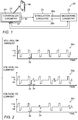
- Fig. 2 is a schematic illustration of various pulse sequences that may be passed between electrodes 26a and 26b, in accordance with some embodiments of the present invention.
- the pulses shown in Fig. 2 may be voltage pulses used for voltage-regulated stimulation, or alternatively, current pulses used for current-regulated stimulation. (Thus, the units of the vertical axes may be any appropriate unit for voltage or current.)
- First sequence 30a is a sequence of stimulating pulses 32, which may be passed between the electrodes while executing a stimulation procedure.
- stimulating pulses 32 have varying intra-pulse amplitudes, such that it may be difficult to use the stimulating pulses to measure the impedance between the electrodes.
- the stimulating pulses may also vary in an inter-pulse manner, such that a particular pulse may have a different amplitude from that of a neighboring pulse.
- a sequence such as second sequence 30b or third sequence 30c, each of which includes a plurality of reference pulses 34 between respective pairs of stimulating pulses, is used, instead of first sequence 30a.
- Reference pulses 34 typically have an amplitude that varies less than the amplitude of the stimulating pulses.
- each reference pulse may have a constant (i.e., "flat") positive ("+ve") amplitude, and a constant negative (“-ve") amplitude.
- reference pulses 34 rather than stimulating pulses 32, may be more easily used to measure the impedance.
- at least some of the reference pulses are passed at regular intervals (i.e., periodically), such that the impedance may be measured at regular intervals.
- At least one pulse of the stimulation procedure is substituted with one of the reference pulses.
- two of the stimulating pulses of sequence 30a are substituted with respective reference pulses.
- no pulse of the stimulation procedure is substituted with a reference pulse.
- sequence 30b two reference pulses are added to sequence 30a, without replacing any of the stimulating pulses.
- the references pulses are added to the stimulating-pulse sequence (as in sequence 30b), rather than substituted for stimulating pulses (as in sequence 30c), unless the frequency of delivery of the stimulating pulses is too high to accommodate the addition of the reference pulses.
- one or more of the reference pulses are symmetric. That is, for one or more of the reference pulses, the duration and amplitude of the positive portion of the pulse are equal to, respectively, the duration and amplitude of the negative portion of the pulse.
- one or more of the reference pulses may be asymmetric. (Even though the integral over an asymmetric pulse is typically zero, the amplitude and duration of the positive portion of the asymmetric pulse are different from the amplitude and duration of the negative portion of the pulse.)
- the reference pulses have an amplitude that is lower than that of the stimulating pulses, and/or a duration that is shorter than that of the stimulating pulses.
- the reference pulses are unlikely to stimulate the subject, and in fact, may not be noticed by the subject at all.
- the amplitude of the current of the reference pulses is less than 15 mA, such as less than 10 mA, e.g., less than 5 mA, and/or the voltage of the reference pulses is less than 15 V, e.g., less than 9 V.
- the duration of the reference pulses may be less than 25 microseconds, e.g., less than 20 microseconds.
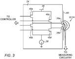
- Fig. 3 is a schematic illustration of stimulation circuitry 24 coupled (e.g., attached) to skin 60 of a subject, in accordance with some embodiments of the present invention. It is noted that the particular configuration shown in Fig. 3 is provided purely by way of example. In practice, any suitable circuitry may be used to apply the stimulating and reference pulses described herein, for either current-regulated or voltage-regulated applications.
- stimulation circuitry 24 comprises the half-bridge circuit shown in Fig. 3 .
- a current source 38 supplies the current that is passed between electrodes 26a and 26b, while the voltage between the electrodes is limited to the voltage supplied by voltage supply 36.
- the current that is passed between the electrodes is the minimum of "I” and "V/R,” where "I” is the current supplied by current source 38, "V” is the voltage supplied by voltage supply 36, and "R” is the impedance of the tissue.
- the controller controls switches (e.g., transistor switches) 40a, 40b, 40c, and 40d.
- the controller closes switches 40a and 40d, thus connecting electrode 26a to voltage supply 36 and electrode 26b to current source 38, while switches 40b and 40c remain open.
- the controller closes switches 40b and 40c, thus connecting electrode 26b to voltage supply 36 and electrode 26a to current source 38, while switches 40a and 40d remain open.
- the direction of current determines the polarity of the pulse.
- the respective positive portions of the pulses shown in Fig. 2 may be obtained by passing current from electrode 26a to electrode 26b, while the respective negative portions may be obtained by passing current from electrode 26b to electrode 26a.
- the degree to which the switches are closed determines the amplitudes of the pulses.
- the voltage supplied by voltage supply 36 is controlled, in response to the measured impedance.
- a "calibration procedure" is performed.
- At least one reference pulse, passed between the electrodes prior to the stimulation procedure, is used to measure the baseline impedance between the electrodes.
- the voltage supply 36 may be set to a voltage that is slightly higher than the product of the measured baseline impedance and the maximum desired stimulation current.
- the above-described calibration procedure is advantageous, in that it facilitates setting a voltage limit that is high enough to accommodate the stimulation of the subject, yet not too high as to consume a relatively large amount of excess power.
- the voltage supply would need to be set, for every subject, as high as needed to accommodate the "worst case scenario," i.e., the highest expected skin impedance.
- the voltage supply would be too high, such that excess power would be needlessly consumed.
- an appropriate voltage limit may be set for each subject, thus facilitating more efficient consumption of power.
- the voltage supply when passing the reference pulse that is used to measure the baseline impedance, the voltage supply is set to a lower voltage than the voltage to which it is subsequently set for the stimulation procedure.
- the voltage supply may be set to a voltage that is slightly higher than the product of the maximum estimated impedance and the desired reference current.
- the voltage supply may be increased in order to accommodate the stimulation, as described above. Since the precision of measuring circuitry 28 ( Fig. 1 ) is typically greater for smaller supplied voltages than for larger supplied voltages, the above-described technique may facilitate a more precise measurement of the baseline impedance. (During the stimulation procedure, however, the voltage supply typically remains at the higher stimulation-accommodating value, even during the application of the reference pulses.)
- reference pulses such as those shown in Fig. 2 may have an amplitude of 10 mA, while skin impedance of human subjects is typically no higher than 1500 Ohm.
- the voltage supply may be set to 18 V, which is slightly higher than the product of 10 mA and 1500 Ohm.
- Stimulation pulses such as those shown in Fig. 2 may have a maximum amplitude of 30 mA.
- the voltage supply for the stimulation procedure may be set to 35 V, which is slightly higher than the product of 30 mA and 1000 Ohm.
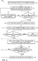
- Fig. 4 is a flow diagram showing a method 58 practiced in accordance with some embodiments of the present invention. Most of the steps in method 58 were already described above, but, for clarity, are again described hereinbelow, with reference to Fig. 4 .
- Method 58 begins with a first voltage-setting step 42, in which voltage supply 36 is set to a voltage that is high enough to accommodate a reference pulse, yet lower than the voltage used subsequently during the stimulation procedure. (As noted above, such a lower voltage may facilitate a more precise measurement of the baseline impedance.) Subsequently, in a baseline-impedance-measuring step 44, at least one reference pulse is applied to the subject by being passed between the electrodes, and during the application of the reference pulse, the baseline impedance is measured, by measuring the voltage between the electrodes.
- the controller assesses whether the measured baseline impedance is reasonable, i.e., whether it falls within an expected range of normal human skin impedance, e.g., 300 - 1500 Ohm. If the baseline impedance is not reasonable (i.e., it is higher than expected, thus indicating that the electrodes may not have been properly coupled to the skin, or it is lower than expected, thus indicating a possible shorting of the electrodes), an alert may be generated, and subsequently, in response to the alert, the coupling (e.g., attachment) of the electrodes to the skin may be adjusted, at a first adjusting step 47. Subsequently, steps 44 and 45 are repeated. (Steps 42, 44, 45, and 47 collectively form part of the calibration procedure referred to above.)
- a second voltage-setting step 46 voltage supply 36 is set, in response to the baseline impedance, to a higher voltage that is high enough to accommodate the stimulation.
- a stimulating step 48 one or more stimulating pulses are applied to the subject, by being passed between the electrodes.
- the controller, or the subject decides whether the stimulation procedure is over, i.e., whether enough stimulating pulses have been applied to the subject. If the answer is affirmative, the stimulation procedure ends.
- the controller compares the intraprocedural impedance to a threshold that is based on the baseline impedance.
- an alert may be generated, and subsequently, in response to the alert, the coupling (e.g., attachment) of the electrodes to the skin may be adjusted, at a second adjusting step 56. Following the adjustment, the stimulation may continue, at stimulating step 48.
- controller circuitry 64 is embodied as a programmable digital computing device comprising a central processing unit (CPU) and random access memory (RAM).
- Program code including software programs, and/or data are loaded into the RAM for execution and processing by the CPU.
- the program code and/or data may be downloaded to the controller in electronic form, over a network, for example, or it may, alternatively or additionally, be provided and/or stored on non-transitory tangible media, such as magnetic, optical, or electronic memory.
- Such program code and/or data when provided to the controller, produce a machine or special-purpose computer, configured to perform the tasks described herein.
- the computer is typically a hardware device programmed with computer program instructions to produce a special purpose computer.
- the operations that are performed by the computer transform the physical state of a memory, which is a real physical article, to have a different magnetic polarity, electrical charge, or the like depending on the technology of the memory that is used.
Description
- The present application claims priority from and is a continuation-in-part of
U.S. Patent Application No. 14/992,046 to Harpak, filed Jan. 11 2016 - The present invention relates to medical procedures, and specifically to electrostimulation of tissue.
- Transcutaneous electrical nerve stimulation (TENS) is the use of electric current produced by a device to stimulate the nerves for therapeutic purposes. Electrical muscle stimulation (EMS), also known as neuromuscular electrical stimulation (NMES) or electromyostimulation, is the elicitation of muscle contraction using electric impulses.
-
US Patent 8 ,620,434 describes a device and method for applying transcutaneous electrical nerve stimulation via an electrode. The device includes the electrode being arranged for detecting a change of a skin impedance and being configured for switching from a stimulation mode of operation for stimulating the nerve, into a recalibration mode of operation upon detection of the changed skin impedance. The device may include a plurality of electrodes being configured for detecting the change of the skin impedance and being configured for adjusting an electrical current flowing through the skin via the plurality of electrodes. -
US Patent Application Publication 2004/0015212 describes improved operating features for an electrotherapy device are provided by the use of a peel off detection system which monitors device operation and provides necessary corrective action where appropriate. More specifically, the electrotherapy device monitors the connection characteristics of the electrodes, in order to determine if acceptable connections are being maintained to the patient. In order to monitor these connections, a baseline signal measurement is made when the system is first started. Subsequent measurements are then compared to this baseline measurement, to insure that the magnitude stays within an acceptable range. If the measurement shows a non-acceptable connection condition, the electrotherapy device is shut down and appropriate warning signals are provided to the user. Where multiple output channels are used, isolation circuits are included in the feedback network in order to insure no signal coupling exists. - An article by Degen and Loeliger, entitled "An improved Method to continuously monitor the Electrode-Skin Impedance during Bioelectric Measurements," published in the Proceedings of the 29th Annual International Conference of the IEEE EMBS, 2007, describes a method that allows to monitor the electrode-skin impedance during bioelectric recordings in a continuous way, without reducing the common mode rejection ratio (CMRR) of the amplifier. The method is based on an additional common mode signal which is superimposed on the bioelectric signal.
-
US Patent 6,217,574 describes an RF ablation system comprising an irrigated split tip electrode catheter, an RF generator and a signal processor. The catheter comprises four orthogonally arranged electrodes at the distal tip. The catheter is used to map the electrical activity of a heart chamber to locate site(s) of aberrant electrical pathways to be ablated. Once an ablation site has been located, the signal processor activates the RF generator to transmit a low level RF current to each electrode member of the split tip electrode. The signal processor receives signals indicative of the impedance between each electrode member and one or more surface indifferent electrodes and determines which electrode members are associated with the highest impedance. Such electrode members are those in greatest contact with the myocardium. The signal processor then automatically activates the RF generator to transmit an RF ablation current to the electrode members in contact with the myocardium to create a lesion. - The invention is defined by the independent claim. In the following any aspect, example and embodiment which does not fall under the scope of the independent claim is not part of the invention. There is provided, in accordance with some applications of the present invention, apparatus for use with (i) stimulation circuitry that includes a pair of electrodes, and (ii) measuring circuitry, the apparatus including:
a controller including: - at least one interface configured to couple the controller to the stimulation circuitry and measuring circuitry; and
- controller circuitry, configured, while the electrodes are coupled to skin of a subject, to:
- execute a stimulation procedure by driving the stimulation circuitry to pass a plurality of stimulating pulses between the pair of electrodes,
- drive the stimulation circuitry to pass one or more reference pulses between the pair of electrodes, the reference pulses being different from each of the stimulating pulses,
- receive, from the measuring circuitry, an impedance between the electrodes that is measured using the reference pulses, and
- in response to the impedance measured using the reference pulses, but not in response to any impedance measured using the stimulating pulses, control the stimulation procedure.
- In some applications, the controller circuitry is configured to control the stimulation procedure in response to the measured impedance by adjusting an amplitude of the stimulating pulses.
- In some applications, the controller circuitry is configured to control the stimulation procedure in response to the measured impedance by generating an alert indicative of a required adjustment to the coupling of the electrodes to the skin.
- In some applications, the controller circuitry is configured to drive the stimulation circuitry to pass the one or more reference pulses between the pair of electrodes by driving the stimulation circuitry to pass one or more symmetric reference pulses.
- In some applications, the controller circuitry is configured to drive the stimulation circuitry to pass the one or more reference pulses between the pair of electrodes by driving the stimulation circuitry to pass one or more asymmetric reference pulses.
- In some applications, the control circuitry is configured to receive, from the measuring circuitry, the impedance between the electrodes that is measured using the reference pulses by receiving, from the measuring circuitry, a voltage between the pair of electrodes during the passing of the reference pulses.
- In some applications, the control circuitry is configured to receive, from the measuring circuitry, the impedance between the electrodes that is measured using the reference pulses by receiving, from the measuring circuitry, a current between the pair of electrodes during the passing of the reference pulses.
- In some applications, the controller circuitry is configured to drive the stimulation circuitry to pass the plurality of stimulating pulses between the pair of electrodes by driving the stimulation circuitry to pass a plurality of current-regulated stimulating pulses.
- In some applications, the controller circuitry is configured to drive the stimulation circuitry to pass the plurality of stimulating pulses between the pair of electrodes by driving the stimulation circuitry to pass a plurality of voltage-regulated stimulating pulses.
- In some applications, the controller circuitry is configured to control the stimulation procedure in response to the measured impedance by controlling a supplied voltage that is used to pass the stimulating pulses between the pair of electrodes.
- In some applications, the controller circuitry is configured to drive the stimulation circuitry to pass the one or more reference pulses between the pair of electrodes by driving the stimulation circuitry to substitute at least one pulse of the stimulation procedure with one of the reference pulses.
- In some applications, the controller circuitry is configured to drive the stimulation circuitry to pass the one or more reference pulses without substituting any pulse of the stimulation procedure with one of the reference pulses.
- In some applications, the controller circuitry is configured to drive the stimulation circuitry to pass the one or more reference pulses between the pair of electrodes by driving the stimulation circuitry to pass at least one reference pulse having an amplitude that varies less than an amplitude of at least one of the stimulating pulses.
- In some applications, the controller circuitry is configured to drive the stimulation circuitry to pass the one or more reference pulses between the electrodes during the stimulation procedure.
- In some applications, the controller circuitry is configured to control the stimulation procedure in response to the measured impedance by stopping the stimulation procedure.
- In some applications, the controller circuitry is configured to drive the stimulation circuitry to pass the one or more reference pulses between the pair of electrodes by driving the stimulation circuitry to pass a plurality of reference pulses between respective pairs of the stimulating pulses.
- In some applications, the controller circuitry is configured to drive the stimulation circuitry to pass the one or more reference pulses between the pair of electrodes by driving the stimulation circuitry to pass the plurality of reference pulses at regular intervals.
- In some applications, the controller circuitry is configured to:
- receive, from the measuring circuitry, a baseline impedance between the electrodes and a subsequent impedance between the electrodes, and
- control the stimulation procedure in response to comparing the subsequent impedance to a threshold that is based on the baseline impedance.
- In some applications, the controller circuitry is further configured to adaptively adjust the threshold during the stimulation procedure.
- In some applications, the controller circuitry is configured to drive the stimulation circuitry to pass one of the reference pulses before the stimulation procedure, the baseline impedance being measured using the reference pulse that is passed before the stimulation procedure.
- In some applications, the controller circuitry is configured to drive the stimulation circuitry to pass the reference pulse before the stimulation procedure using a first supplied voltage that is lower than a second supplied voltage that is used to pass the stimulating pulses between the pair of electrodes.
- In some applications, the controller circuitry is configured to drive the stimulation circuitry to pass the one or more reference pulses between the pair of electrodes by driving the stimulation circuitry to pass at least one reference pulse having a lower amplitude than an amplitude of at least one of the stimulating pulses.
- In some applications, the controller circuitry is configured to drive the stimulation circuitry to pass the at least one reference pulse by driving the stimulation circuitry to pass at least one reference pulse having a current that is less than 15 mA.
- In some applications, the controller circuitry is configured to drive the stimulation circuitry to pass the at least one reference pulse by driving the stimulation circuitry to pass at least one reference pulse having a current that is less than 10 mA.
- In some applications, the controller circuitry is configured to drive the stimulation circuitry to pass the at least one reference pulse by driving the stimulation circuitry to pass at least one reference pulse having a current that is less than 5 mA.
- In some applications, the controller circuitry is configured to drive the stimulation circuitry to pass the at least one reference pulse by driving the stimulation circuitry to pass at least one reference pulse having a voltage that is less than 15 V.
- In some applications, the controller circuitry is configured to drive the stimulation circuitry to pass the at least one reference pulse by driving the stimulation circuitry to pass at least one reference pulse having a voltage that is less than 9 V.
- In some applications, the controller circuitry is configured to drive the stimulation circuitry to pass the one or more reference pulses between the pair of electrodes by driving the stimulation circuitry to pass at least one reference pulse having a shorter duration than a duration of at least one of the stimulating pulses.
- In some applications, the controller circuitry is configured to drive the stimulation circuitry to pass the at least one reference pulse by driving the stimulation circuitry to pass at least one reference pulse having a duration of less than 25 microseconds.
- There is further provided, in accordance with some applications of the present invention, a method, including:
- executing a stimulation procedure, by passing a plurality of stimulating pulses between a pair of electrodes coupled to skin of a subject;
- passing one or more reference pulses between the pair of electrodes, the reference pulses being different from each of the stimulating pulses;
- measuring an impedance between the electrodes, using the reference pulses; and
- in response to the impedance measured using the reference pulses, but not in response to any impedance measured using the stimulating pulses, controlling the stimulation procedure.
- There is additionally provided, in accordance with some applications of the present invention, a controller for use with (i) stimulation circuitry that includes a pair of electrodes, and (ii) measuring circuitry, the controller including:
- at least one interface configured to couple the controller to the stimulation circuitry and measuring circuitry; and
- controller circuitry, configured to, while the electrodes are coupled to skin of a subject:
- via the interface:
- execute a stimulation procedure by driving the stimulation circuitry to pass a plurality of stimulating pulses between the pair of electrodes,
- drive the stimulation circuitry to pass one or more reference pulses between the pair of electrodes, the reference pulses being different from each of the stimulating pulses, and
- receive, from the measuring circuitry, an impedance between the electrodes that is measured using the reference pulses, and
- in response to the impedance measured using the reference pulses, but not in response to any impedance measured using the stimulating pulses, control the stimulation procedure.
- via the interface:
- There is further provided, in accordance with some applications of the present invention, apparatus including:
- stimulation circuitry comprising a pair of electrodes,
- measuring circuitry; and
- a controller, the controller comprising:
- at least one interface configured to couple the controller to the stimulation circuitry and measuring circuitry; and
- controller circuitry, configured, while the electrodes are coupled to skin of a subject to:
- execute a stimulation procedure by driving the stimulation circuitry to pass a plurality of stimulating pulses between the pair of electrodes,
- drive the stimulation circuitry to pass one or more reference pulses between the pair of electrodes, the reference pulses being different from each of the stimulating pulses,
- receive, from the measuring circuitry, an impedance between the electrodes that is measured using the reference pulses, and
- in response to the impedance measured using the reference pulses, but not in response to any impedance measured using the stimulating pulses, control the stimulation procedure.
- The present invention will be more fully understood from the following detailed description of embodiments thereof, taken together with the drawings, in which:
-
-
Fig. 1 is a block diagram of a system for applying, and monitoring impedance during, electrostimulation, in accordance with some embodiments of the present invention; -
Fig. 2 is a schematic illustration of various pulse sequences that may be passed between electrodes, in accordance with some embodiments of the present invention; -
Fig. 3 is a schematic circuit diagram of stimulation circuitry coupled (e.g., attached) to skin of a subject, in accordance with some embodiments of the present invention; and -
Fig. 4 is a flow diagram showing a method for electrostimulation practiced in accordance with some embodiments of the present invention. - In electrostimulation procedures, at least two electrodes are coupled (e.g., attached) to the skin of the subject, and subsequently, a plurality of stimulating pulses are passed between the electrodes. In current-regulated stimulation, a predefined amount of current is passed between the electrodes during each the stimulating pulses. In voltage-regulated stimulation, a predefined amount of voltage is applied between the electrodes during each of the stimulating pulses.
- In some cases, the electrodes might not be properly coupled (e.g., attached) to the skin before the procedure. Alternatively or additionally, the electrodes may become at least partially uncoupled from the skin, or shorted to one another, during the procedure, e.g., due to movement of the subject or degradation of the adhesive material that keeps the electrodes coupled to the skin. Such a scenario may lead to inefficient power consumption, and/or lessen the effectiveness of the stimulation. For example, if the impedance between the electrodes is higher than normal due to improper coupling of the electrodes to the skin, it may be necessary, for current-regulated stimulation, to increase the supplied voltage that supplies the stimulating current, thus consuming more power than would otherwise be necessary. For voltage-regulated stimulation, the increased impedance may cause a smaller amount of current to pass between the electrodes, thus lessening the effectiveness of the stimulation.
- In light of the above, it may be advantageous, before and/or during the stimulation procedure, to measure the impedance between the electrodes, such that, if the measured impedance deviates from a particular threshold, the coupling (e.g., attachment) of the electrodes to the skin may be adjusted. To measure the impedance, the voltage between the electrodes may be measured while a current of known amplitude is passed between the electrodes. Alternatively, the current between the electrodes may be measured while a voltage of known amplitude is applied between the electrodes.
- One implementation of the above-described impedance measurement is to measure the voltage or current between the electrodes while the stimulating pulses are passed between the electrodes. However, pulse parameters that are suitable for stimulation are not necessarily suitable for impedance measurement, and vice versa. For example, in many cases, the amplitude of the stimulating pulses varies over time in an "intra-pulse" and/or "inter-pulse" manner, thus rendering it difficult to use the stimulating pulses to accurately measure the impedance. That is, at least some of the stimulating pulses may have a varying amplitude, and/or the respective amplitudes of the stimulating pulses may be varied during the stimulation procedure, as the subject tries to find his "comfort zone."
- In light of the above, embodiments of the present invention provide an improved implementation, in which one or more reference pulses are passed between the electrodes, in addition to the stimulating pulses. The reference pulses, but not the stimulating pulses, are used for impedance measurement, while the stimulating pulses, but typically not the reference pulses, are used for stimulation. Parameters such as pulse amplitude, duration, and frequency may be "tailored" differently for each type of pulse, thus facilitating effective stimulation and impedance monitoring. For example, in some embodiments of the present invention, the amplitude of the reference pulses is less time-varying than that of the stimulating pulses (and in fact, is often set to a constant value), thus allowing the reference pulses to be used to accurately measure the impedance between the electrodes.
- Reference is initially made to
Fig. 1 , which is a block diagram of asystem 20 for applying, and monitoring impedance during electrostimulation, in accordance with some embodiments of the present invention.System 20 comprises a controller 22 (e.g., a programmable controller configured to execute, for example, microcode),stimulation circuitry 24 comprising at least a pair ofelectrodes circuitry 28.Controller 22 comprises at least one interface 62 (e.g., an electric interface, such as a plug or socket) that couples the controller tostimulation circuitry 24 and measuringcircuitry 28, and further comprisescontroller circuitry 64. -
Electrodes controller circuitry 64drives stimulation circuitry 24 to pass a plurality of stimulating pulses between the electrodes. As further described hereinbelow,controller circuitry 64 may also drive the stimulation circuitry to pass one or more reference pulses between the pair of electrodes before and/or during the electrostimulation procedure, the reference pulses being different from each of the stimulating pulses. During the application of the reference pulses, but not during the application of the stimulating pulses, the controller circuitrydrives measuring circuitry 28 to measure a voltage or current between the electrodes. The measuring circuitry passes the measured voltage or current to the controller circuitry, which then uses the quantity from the measuring circuitry to measure the impedance between the electrodes. In this manner, the reference pulses, but not the stimulating pulses, are used to measure the impedance. In any case, even if some impedances are measured using the stimulating pulses, the controller circuitry controls the stimulation procedure in response to impedance(s) measured using the reference pulses, but not in response to any impedance measured using the stimulating pulses. - Typically, at least one of the reference pulses is used to measure a baseline impedance between the electrodes. This reference pulse may be passed before the stimulation procedure (after coupling the electrodes to the skin), or during the procedure (e.g., near the beginning of the procedure). Subsequently, during the procedure, at least one reference pulse is used to measure a subsequent impedance between the electrodes, which, for ease of description, is referred to below as the "intraprocedural impedance." The intraprocedural impedance may be compared to a threshold that is based on the baseline impedance, and, in response thereto, the stimulation procedure may be controlled. For example, if the intraprocedural impedance deviates from the threshold, the controller circuitry may generate an alert that indicates that the coupling of the electrodes to the skin needs to be adjusted. (In some embodiments, the controller circuitry generates the alert by wirelessly or wiredly driving a
smartphone 66 of the subject to display an appropriate message to the subject.) Further to receiving the alert, the subject may adjust the coupling (e.g., attachment) of the electrodes to the skin, e.g., by reapplying adhesive material at the electrode-skin interface for at least one of the electrodes. - In some embodiments, if the intraprocedural impedance deviates from the threshold, the controller circuitry stops the stimulation procedure, alternatively or additionally to generating the alert. While the stimulation procedure is stopped, the coupling (e.g., attachment) of the electrodes to the skin may be adjusted, and subsequently, the stimulation procedure may be restarted.
- The above-described threshold may, for example, be a range of values having a lower bound that is slightly less than the baseline impedance, and an upper bound that is slightly greater than the baseline impedance, such that the intraprocedural impedance is considered to deviate from the threshold whether it is greater than the upper bound or lower than the lower bound. Alternatively, the threshold may be a single value (e.g., the baseline impedance plus or minus some margin), and the intraprocedural impedance may be considered to deviate from the threshold if it is greater than the threshold, or alternatively, if it is lower than the threshold.
- In some embodiments, the threshold is adaptively adjusted during the stimulation procedure. For example, in some embodiments, the threshold is periodically lowered during the stimulation procedure, to account for the expected decrease in impedance during the procedure caused by sweating of the subject. Alternatively or additionally, the threshold may be adjusted in response to any other relevant factors.
- Alternatively or additionally, in response to measuring the baseline and/or intraprocedural impedance between the electrodes, the amplitude of the stimulating pulses may be adjusted. For example, the amplitude of the stimulating current may be set as an increasing function of the measured impedance, since a higher impedance may be indicative of a greater amount of body fat in the subject, which, in turn, indicates that a stronger current is needed to reach the subject's nerve or muscle. Typically, the controller circuitry is configured to differentiate a stable, high-but-normal impedance from an abnormally high and/or increasing impedance. For the former type of impedance, the controller circuitry typically adjusts the amplitude of the stimulating pulses, as described immediately above. For the latter type of impedance, on the other hand, the controller circuitry typically generates an alert and/or stops the procedure, as described above.
- Reference is now made to
Fig. 2 , which is a schematic illustration of various pulse sequences that may be passed betweenelectrodes Fig. 2 may be voltage pulses used for voltage-regulated stimulation, or alternatively, current pulses used for current-regulated stimulation. (Thus, the units of the vertical axes may be any appropriate unit for voltage or current.) -
First sequence 30a is a sequence of stimulatingpulses 32, which may be passed between the electrodes while executing a stimulation procedure. As shown in the figure, stimulatingpulses 32 have varying intra-pulse amplitudes, such that it may be difficult to use the stimulating pulses to measure the impedance between the electrodes. (As noted above, the stimulating pulses may also vary in an inter-pulse manner, such that a particular pulse may have a different amplitude from that of a neighboring pulse.) Hence, in embodiments of the present invention, a sequence such assecond sequence 30b orthird sequence 30c, each of which includes a plurality ofreference pulses 34 between respective pairs of stimulating pulses, is used, instead offirst sequence 30a. -
Reference pulses 34 typically have an amplitude that varies less than the amplitude of the stimulating pulses. For example, as shown inFig. 2 , each reference pulse may have a constant (i.e., "flat") positive ("+ve") amplitude, and a constant negative ("-ve") amplitude. Hence, as noted above,reference pulses 34, rather than stimulatingpulses 32, may be more easily used to measure the impedance. Typically, as shown inFig. 2 , at least some of the reference pulses are passed at regular intervals (i.e., periodically), such that the impedance may be measured at regular intervals. - In some embodiments, at least one pulse of the stimulation procedure is substituted with one of the reference pulses. For example, in
sequence 30c, two of the stimulating pulses ofsequence 30a are substituted with respective reference pulses. In other embodiments, no pulse of the stimulation procedure is substituted with a reference pulse. For example, insequence 30b, two reference pulses are added tosequence 30a, without replacing any of the stimulating pulses. Typically, the references pulses are added to the stimulating-pulse sequence (as insequence 30b), rather than substituted for stimulating pulses (as insequence 30c), unless the frequency of delivery of the stimulating pulses is too high to accommodate the addition of the reference pulses. - In some embodiments, as shown in
Fig. 2 , one or more of the reference pulses are symmetric. That is, for one or more of the reference pulses, the duration and amplitude of the positive portion of the pulse are equal to, respectively, the duration and amplitude of the negative portion of the pulse. Alternatively or additionally, one or more of the reference pulses may be asymmetric. (Even though the integral over an asymmetric pulse is typically zero, the amplitude and duration of the positive portion of the asymmetric pulse are different from the amplitude and duration of the negative portion of the pulse.) - Typically, as shown in
Fig. 2 , the reference pulses have an amplitude that is lower than that of the stimulating pulses, and/or a duration that is shorter than that of the stimulating pulses. Hence, the reference pulses are unlikely to stimulate the subject, and in fact, may not be noticed by the subject at all. For example, in some embodiments, the amplitude of the current of the reference pulses is less than 15 mA, such as less than 10 mA, e.g., less than 5 mA, and/or the voltage of the reference pulses is less than 15 V, e.g., less than 9 V. Alternatively or additionally, the duration of the reference pulses may be less than 25 microseconds, e.g., less than 20 microseconds. - Reference is now made to
Fig. 3 , which is a schematic illustration ofstimulation circuitry 24 coupled (e.g., attached) toskin 60 of a subject, in accordance with some embodiments of the present invention. It is noted that the particular configuration shown inFig. 3 is provided purely by way of example. In practice, any suitable circuitry may be used to apply the stimulating and reference pulses described herein, for either current-regulated or voltage-regulated applications. - In some current-regulated stimulation embodiments,
stimulation circuitry 24 comprises the half-bridge circuit shown inFig. 3 . In such a circuit, acurrent source 38 supplies the current that is passed betweenelectrodes voltage supply 36. (In other words, the current that is passed between the electrodes is the minimum of "I" and "V/R," where "I" is the current supplied bycurrent source 38, "V" is the voltage supplied byvoltage supply 36, and "R" is the impedance of the tissue.) To generate pulses of current such as the stimulation and reference pulses shown inFig. 2 , the controller controls switches (e.g., transistor switches) 40a, 40b, 40c, and 40d. In particular, to pass current fromelectrode 26a toelectrode 26b, the controller closesswitches electrode 26a tovoltage supply 36 andelectrode 26b tocurrent source 38, whileswitches electrode 26b toelectrode 26a, the controller closesswitches electrode 26b tovoltage supply 36 andelectrode 26a tocurrent source 38, whileswitches - The direction of current determines the polarity of the pulse. For example, the respective positive portions of the pulses shown in
Fig. 2 may be obtained by passing current fromelectrode 26a toelectrode 26b, while the respective negative portions may be obtained by passing current fromelectrode 26b toelectrode 26a. The degree to which the switches are closed determines the amplitudes of the pulses. - In the embodiment of the invention, the voltage supplied by
voltage supply 36 is controlled, in response to the measured impedance. For example, in the embodiment of the invention, a "calibration procedure" is performed. At least one reference pulse, passed between the electrodes prior to the stimulation procedure, is used to measure the baseline impedance between the electrodes. Subsequently, thevoltage supply 36 may be set to a voltage that is slightly higher than the product of the measured baseline impedance and the maximum desired stimulation current. - The above-described calibration procedure is advantageous, in that it facilitates setting a voltage limit that is high enough to accommodate the stimulation of the subject, yet not too high as to consume a relatively large amount of excess power. In other words, if the voltage supply were set without regard to the baseline impedance, the voltage supply would need to be set, for every subject, as high as needed to accommodate the "worst case scenario," i.e., the highest expected skin impedance. However, some subjects may have a skin impedance that is significantly lower than the highest expected skin impedance. For such subjects, the voltage supply would be too high, such that excess power would be needlessly consumed. Hence, by setting the voltage supply in response to the measured baseline impedance, an appropriate voltage limit may be set for each subject, thus facilitating more efficient consumption of power.
- Typically, when passing the reference pulse that is used to measure the baseline impedance, the voltage supply is set to a lower voltage than the voltage to which it is subsequently set for the stimulation procedure. For example, the voltage supply may be set to a voltage that is slightly higher than the product of the maximum estimated impedance and the desired reference current. Subsequently, in response to the measured baseline impedance, the voltage supply may be increased in order to accommodate the stimulation, as described above. Since the precision of measuring circuitry 28 (
Fig. 1 ) is typically greater for smaller supplied voltages than for larger supplied voltages, the above-described technique may facilitate a more precise measurement of the baseline impedance. (During the stimulation procedure, however, the voltage supply typically remains at the higher stimulation-accommodating value, even during the application of the reference pulses.) - For example, reference pulses such as those shown in
Fig. 2 may have an amplitude of 10 mA, while skin impedance of human subjects is typically no higher than 1500 Ohm. Thus, during the calibration procedure, the voltage supply may be set to 18 V, which is slightly higher than the product of 10 mA and 1500 Ohm. Stimulation pulses such as those shown inFig. 2 may have a maximum amplitude of 30 mA. Thus, if, for example, the measured baseline impedance was 1000 Ohm, the voltage supply for the stimulation procedure may be set to 35 V, which is slightly higher than the product of 30 mA and 1000 Ohm. - Reference is now made to
Fig. 4 , which is a flow diagram showing amethod 58 practiced in accordance with some embodiments of the present invention. Most of the steps inmethod 58 were already described above, but, for clarity, are again described hereinbelow, with reference toFig. 4 . -
Method 58 begins with a first voltage-settingstep 42, in whichvoltage supply 36 is set to a voltage that is high enough to accommodate a reference pulse, yet lower than the voltage used subsequently during the stimulation procedure. (As noted above, such a lower voltage may facilitate a more precise measurement of the baseline impedance.) Subsequently, in a baseline-impedance-measuringstep 44, at least one reference pulse is applied to the subject by being passed between the electrodes, and during the application of the reference pulse, the baseline impedance is measured, by measuring the voltage between the electrodes. At afirst decision step 45, the controller assesses whether the measured baseline impedance is reasonable, i.e., whether it falls within an expected range of normal human skin impedance, e.g., 300 - 1500 Ohm. If the baseline impedance is not reasonable (i.e., it is higher than expected, thus indicating that the electrodes may not have been properly coupled to the skin, or it is lower than expected, thus indicating a possible shorting of the electrodes), an alert may be generated, and subsequently, in response to the alert, the coupling (e.g., attachment) of the electrodes to the skin may be adjusted, at afirst adjusting step 47. Subsequently, steps 44 and 45 are repeated. (Steps 42, 44, 45, and 47 collectively form part of the calibration procedure referred to above.) - Following an assessment that the baseline impedance is reasonable, at a second voltage-setting
step 46,voltage supply 36 is set, in response to the baseline impedance, to a higher voltage that is high enough to accommodate the stimulation. Next, at a stimulatingstep 48, one or more stimulating pulses are applied to the subject, by being passed between the electrodes. At asecond decision step 50, the controller, or the subject, decides whether the stimulation procedure is over, i.e., whether enough stimulating pulses have been applied to the subject. If the answer is affirmative, the stimulation procedure ends. Otherwise, depending on the current state of the stimulation procedure, either (i) more stimulating pulses are applied to the subject, at stimulatingstep 48, or (ii) at an intraprocedural-impedance-measuringstep 52, at least one reference pulse is applied to the subject, and during the application of the reference pulse, the intraprocedural impedance between the electrodes is measured. Subsequently to (ii), at athird decision step 54, the controller compares the intraprocedural impedance to a threshold that is based on the baseline impedance. If the intraprocedural impedance deviates from the threshold (i.e., it is higher than the threshold, thus indicating a possible decoupling of the electrodes from the skin, or it is lower than the threshold, thus indicating a possible shorting of the electrodes), an alert may be generated, and subsequently, in response to the alert, the coupling (e.g., attachment) of the electrodes to the skin may be adjusted, at asecond adjusting step 56. Following the adjustment, the stimulation may continue, at stimulatingstep 48. - In some embodiments,
controller circuitry 64 is embodied as a programmable digital computing device comprising a central processing unit (CPU) and random access memory (RAM). Program code, including software programs, and/or data are loaded into the RAM for execution and processing by the CPU. The program code and/or data may be downloaded to the controller in electronic form, over a network, for example, or it may, alternatively or additionally, be provided and/or stored on non-transitory tangible media, such as magnetic, optical, or electronic memory. Such program code and/or data, when provided to the controller, produce a machine or special-purpose computer, configured to perform the tasks described herein. The computer is typically a hardware device programmed with computer program instructions to produce a special purpose computer. Typically, the operations that are performed by the computer transform the physical state of a memory, which is a real physical article, to have a different magnetic polarity, electrical charge, or the like depending on the technology of the memory that is used. - It will be appreciated by persons skilled in the art that the present invention is not limited to what has been particularly shown and described hereinabove. Rather, the scope of the present invention includes both combinations and subcombinations of the various features described hereinabove, as well as variations and modifications thereof that are not in the prior art, which would occur to persons skilled in the art upon reading the foregoing description.
Claims (15)
- Apparatus for use with (i) stimulation circuitry (24) that includes a pair of electrodes (26a, 26b), (ii) measuring circuitry (28), and (iii) a voltage supply (36), the apparatus comprising a controller (22) comprising:at least one interface (62) configured to couple the controller (22) to the stimulation circuitry (24) and measuring circuitry (28); andcontroller circuitry (64), configured, while the electrodes (26a, 26b) are coupled to skin of a subject, to perform a stimulation procedure by:driving the stimulation circuitry (24) to pass a plurality of stimulating pulses between the pair of electrodes (26a, 26b),driving the stimulation circuitry (24) to pass one or more intraprocedural-reference pulses between the pair of electrodes (26a, 26b), the reference pulses being different from each of the stimulating pulses,receiving, from the measuring circuitry (28), an intraprocedural impedance between the electrodes (26a, 26b) that is measured using the intraprocedural-reference pulses, andin response to the impedance measured using the intraprocedural-reference pulses, but not in response to any impedance measured using the stimulating pulses, controlling the stimulation procedure:the controller circuitry (64) is configured, while the electrodes (26a, 26b) are coupled to the skin of the subject, to perform a calibration procedure prior to the stimulation procedure, by:driving the stimulation circuitry (24) to pass a calibration-reference pulse via the pair of electrodes (26a, 26b),measuring a baseline impedance between the pair of electrodes (26a, 26b), andcharacterized in that:setting the voltage supply (36) to a voltage that is slightly higher than the product of the measured baseline impedance and a maximum desired stimulation current, andthe controller circuitry (64) is configured to use the voltage supply (36), set to the slightly higher voltage, for performing the stimulation procedure.
- The apparatus according to claim 1, wherein the controller circuitry (64) is configured to drive the stimulation circuitry (24) to pass the one or more intraprocedural-reference pulses between the pair of electrodes (26a, 26b) by driving the stimulation circuitry (24) to pass one or more symmetric intraprocedural-reference pulses.
- The apparatus according to claim 1, wherein the controller circuitry (64) is configured to drive the stimulation circuitry (24) to pass the one or more intraprocedural-reference pulses between the pair of electrodes (26a, 26b) by driving the stimulation circuitry (24) to pass one or more asymmetric intraprocedural-reference pulses.
- The apparatus according to claim 1, wherein the controller circuitry (64) is configured to drive the stimulation circuitry (24) to pass the one or more intraprocedural-reference pulses between the pair of electrodes (26a, 26b) by driving the stimulation circuitry (24) to substitute at least one pulse of the stimulation procedure with one of the intraprocedural-reference pulses.
- The apparatus according to claim 1, wherein the controller circuitry (64) is configured to drive the stimulation circuitry (24) to pass the one or more intraprocedural-reference pulses without substituting any pulse of the stimulation procedure with one of the intraprocedural-reference pulses.
- The apparatus according to claim 1, wherein the controller circuitry (64) is configured to drive the stimulation circuitry (24) to pass the one or more intraprocedural-reference pulses between the pair of electrodes (26a, 26b) by driving the stimulation circuitry (24) to pass at least one intraprocedural-reference pulse having an amplitude that varies less than an amplitude of at least one of the stimulating pulses.
- The apparatus according to any one of claims 1-6, wherein the controller circuitry (64) is configured to control the stimulation procedure in response to the measured intraprocedural impedance by stopping the stimulation procedure.
- The apparatus according to any one of claims 1-6, wherein the controller circuitry (64) is configured to drive the stimulation circuitry (24) to pass the one or more intraprocedural-reference pulses between the pair of electrodes (26a, 26b) by driving the stimulation circuitry (24) to pass a plurality of intraprocedural-reference pulses between respective pairs of the stimulating pulses.
- The apparatus according to any one of claims 1-6, wherein the controller circuitry (64) is configured to:receive, from the measuring circuitry (28), the baseline impedance between the electrodes (26a, 26b) before receiving the intraprocedural impedance between the electrodes (26a, 26b), andcontrol the stimulation procedure in response to comparing the intraprocedural impedance to a threshold that is based on the baseline impedance.
- The apparatus according to claim 9, wherein the controller circuitry (64) is further configured to adaptively adjust the threshold during the stimulation procedure.
- The apparatus according to any one of claims 1-6, wherein the controller circuitry (64) is configured to drive the stimulation circuitry (24) to pass the one or more intraprocedural-reference pulses between the pair of electrodes (26a, 26b) by driving the stimulation circuitry (24) to pass at least one intraprocedural-reference pulse having a lower amplitude than an amplitude of at least one of the stimulating pulses.
- The apparatus according to claim 11, wherein the controller circuitry (64) is configured to drive the stimulation circuitry (24) to pass the at least one intraprocedural-reference pulse by driving the stimulation circuitry (24) to pass at least one intraprocedural-reference pulse having a current that is less than 15 mA.
- The apparatus according to claim 12, wherein the controller circuitry (64) is configured to drive the stimulation circuitry (24) to pass the at least one intraprocedural-reference pulse by driving the stimulation circuitry (24) to pass at least one intraprocedural-reference pulse having a current that is less than 10 mA.
- The apparatus according to claim 11, wherein the controller circuitry (64) is configured to drive the stimulation circuitry (24) to pass the at least one intraprocedural-reference pulse by driving the stimulation circuitry (24) to pass at least one intraprocedural-reference pulse having a voltage that is less than 15 V.
- The apparatus according to any one of claims 1-6, wherein the controller circuitry (64) is configured to drive the stimulation circuitry to pass the one or more intraprocedural-reference pulses between the pair of electrodes (26a, 26b) by driving the stimulation circuitry to pass at least one intraprocedural-reference pulse having a shorter duration than a duration of at least one of the stimulating pulses.
Applications Claiming Priority (2)
| Application Number | Priority Date | Filing Date | Title |
|---|---|---|---|
| US14/992,046 US9895533B2 (en) | 2016-01-11 | 2016-01-11 | Impedance monitoring during electrostimulation |
| PCT/IL2017/050028 WO2017122195A1 (en) | 2016-01-11 | 2017-01-10 | Impedance monitoring during electrostimulation |
Publications (2)
| Publication Number | Publication Date |
|---|---|
| EP3402564A1 EP3402564A1 (en) | 2018-11-21 |
| EP3402564B1 true EP3402564B1 (en) | 2020-03-25 |
Family
ID=57960568
Family Applications (1)
| Application Number | Title | Priority Date | Filing Date |
|---|---|---|---|
| EP17702959.2A Active EP3402564B1 (en) | 2016-01-11 | 2017-01-10 | Impedance monitoring during electrostimulation |
Country Status (5)
| Country | Link |
|---|---|
| US (1) | US9895533B2 (en) |
| EP (1) | EP3402564B1 (en) |
| JP (1) | JP6674046B2 (en) |
| ES (1) | ES2794833T3 (en) |
| WO (1) | WO2017122195A1 (en) |
Families Citing this family (13)
| Publication number | Priority date | Publication date | Assignee | Title |
|---|---|---|---|---|
| PL3244965T3 (en) | 2015-01-13 | 2023-07-24 | Theranica Bio-Electronics Ltd. | Treatment of headaches by electrical stimulation |
| EP3519038B1 (en) | 2016-09-29 | 2020-08-12 | Theranica Bio-Electronics Ltd. | Apparatus for applying an electrical signal to a subject |
| KR102527746B1 (en) | 2017-05-21 | 2023-05-02 | 테라니카 바이오-일렉트로닉스 리미티드 | A device that provides pain relief treatment |
| JP6907783B2 (en) * | 2017-07-27 | 2021-07-21 | オムロンヘルスケア株式会社 | Electrotherapy device, control method, and treatment system |
| BR102017026510A2 (en) * | 2017-12-08 | 2019-06-25 | Fundação Universidade De Brasilia/Centro De Apoio Ao Desenvolvimento Tecnológico | DEVICE FOR NEUROMUSCULAR ELETROESTIMULATION OF LONG-DURATION MULTICANESIS WITH RECALIBRATION THROUGH BIOFEEDBACK |
| US20200306534A1 (en) * | 2017-12-20 | 2020-10-01 | Galvani Bioelectronics Limited | Neural interface device for stimulation of a nerve and measuring impedance |
| EP3737456A1 (en) | 2018-01-11 | 2020-11-18 | Theranica Bio-Electronics Ltd. | Electrode patch |
| RU185257U1 (en) * | 2018-08-06 | 2018-11-28 | Василий Викторович Дьяконов | Detachable suit block for electromyostimulation |
| US10603492B2 (en) | 2018-08-31 | 2020-03-31 | Avation Medical, Inc. | System, method, and apparatus for applying transcutaneous electrical stimulation |
| US11571569B2 (en) | 2019-02-15 | 2023-02-07 | Pulse Biosciences, Inc. | High-voltage catheters for sub-microsecond pulsing |
| EP3842094A1 (en) * | 2019-12-23 | 2021-06-30 | Tesla Medical s.r.o. | Neuromodulation apparatus |
| GB2608006B (en) * | 2020-08-20 | 2024-04-10 | Actegy Ltd | Apparatus for detecting electrical conductivity |
| US20230381513A1 (en) * | 2020-10-10 | 2023-11-30 | NMES Group AB | Neuromuscular electrical stimulation device with automated switchable regulation technologies |
Family Cites Families (10)
| Publication number | Priority date | Publication date | Assignee | Title |
|---|---|---|---|---|
| DE3346744A1 (en) * | 1983-12-23 | 1985-07-04 | MEDEL Medizinische Elektronik Handelsges. mbH, 2000 Hamburg | CIRCUIT ARRANGEMENT FOR CHECKING THE POSITION OF ELECTRODES |
| US6210406B1 (en) | 1998-12-03 | 2001-04-03 | Cordis Webster, Inc. | Split tip electrode catheter and signal processing RF ablation system |
| US20040015212A1 (en) | 2002-05-31 | 2004-01-22 | Empi, Corp. | Electrotherapy stimulation device having electrode peel off detection capabilities |
| EP2288408B1 (en) | 2008-05-16 | 2013-07-17 | Koninklijke Philips Electronics N.V. | A method and system for dynamic recalibration of tens stimulation points to compensate for changing electrode conditions with fail-safe and auto-recovery functionality |
| US8311639B2 (en) * | 2009-07-08 | 2012-11-13 | Nevro Corporation | Systems and methods for adjusting electrical therapy based on impedance changes |
| US9020589B2 (en) | 2010-04-27 | 2015-04-28 | Medtronic, Inc. | Electrical stimulator with voltage mode emulation using regulated current |
| WO2011155089A1 (en) * | 2010-06-07 | 2011-12-15 | 国立大学法人電気通信大学 | Electrical stimulation device and electrical stimulation method |
| US20150257970A1 (en) | 2011-02-17 | 2015-09-17 | Martin Mücke | Device and method for reducing pain |
| AU2013296823A1 (en) | 2012-07-28 | 2015-03-19 | Thimble Bioelectronics, Inc. | System and method for managing pain |
| ES2879286T3 (en) | 2013-03-29 | 2021-11-22 | Gsk Consumer Healthcare Sarl | Skin electrode detachment detection using electrocutaneous impedance |
-
2016
- 2016-01-11 US US14/992,046 patent/US9895533B2/en active Active
-
2017
- 2017-01-10 EP EP17702959.2A patent/EP3402564B1/en active Active
- 2017-01-10 JP JP2018555316A patent/JP6674046B2/en active Active
- 2017-01-10 ES ES17702959T patent/ES2794833T3/en active Active
- 2017-01-10 WO PCT/IL2017/050028 patent/WO2017122195A1/en active Application Filing
Non-Patent Citations (1)
| Title |
|---|
| None * |
Also Published As
| Publication number | Publication date |
|---|---|
| WO2017122195A1 (en) | 2017-07-20 |
| US20170197077A1 (en) | 2017-07-13 |
| US9895533B2 (en) | 2018-02-20 |
| JP6674046B2 (en) | 2020-04-01 |
| ES2794833T3 (en) | 2020-11-19 |
| JP2019501003A (en) | 2019-01-17 |
| EP3402564A1 (en) | 2018-11-21 |
Similar Documents
| Publication | Publication Date | Title |
|---|---|---|
| EP3402564B1 (en) | Impedance monitoring during electrostimulation | |
| US20230293889A1 (en) | Systems and methods for detecting faults and/or adjusting electrical therapy based on impedance changes | |
| US8131357B2 (en) | Apparatus and methods for detecting migration of neurostimulation leads | |
| US9132272B2 (en) | Methods and systems for automatically turning on and off DRG stimulation and adjusting DRG stimulation parameters | |
| AU2014293164B2 (en) | Systems of providing modulation therapy without perception | |
| US9662488B2 (en) | Systems and methods for selectively migrating cells using electric fields | |
| US20110077698A1 (en) | Method and circuitry for measurement of stimulation current | |
| CA3019237A1 (en) | Method and device for transdermally applying electrical stimulation to a region of the head having high impedance | |
| EP3973907B1 (en) | Detecting electrode contact using absolute and relative thresholds | |
| US11819693B2 (en) | Systems and methods for direct suppression of nerve cells | |
| US20220401730A1 (en) | Neurostimulation waveforms having a base component and a high frequency component, and associated systems and methods | |
| CN219109714U (en) | Electrotherapy generator and system | |
| US20220339442A1 (en) | System and Methods Facilitating Sensing Responsive Signals in Association With Paresthesia-Free Stimulation | |
| JP2014176532A (en) | Nerve stimulation apparatus |
Legal Events
| Date | Code | Title | Description |
|---|---|---|---|
| STAA | Information on the status of an ep patent application or granted ep patent |
Free format text: STATUS: UNKNOWN |
|
| STAA | Information on the status of an ep patent application or granted ep patent |
Free format text: STATUS: THE INTERNATIONAL PUBLICATION HAS BEEN MADE |
|
| PUAI | Public reference made under article 153(3) epc to a published international application that has entered the european phase |
Free format text: ORIGINAL CODE: 0009012 |
|
| STAA | Information on the status of an ep patent application or granted ep patent |
Free format text: STATUS: REQUEST FOR EXAMINATION WAS MADE |
|
| 17P | Request for examination filed |
Effective date: 20180716 |
|
| AK | Designated contracting states |
Kind code of ref document: A1 Designated state(s): AL AT BE BG CH CY CZ DE DK EE ES FI FR GB GR HR HU IE IS IT LI LT LU LV MC MK MT NL NO PL PT RO RS SE SI SK SM TR |
|
| AX | Request for extension of the european patent |
Extension state: BA ME |
|
| DAV | Request for validation of the european patent (deleted) | ||
| DAX | Request for extension of the european patent (deleted) | ||
| GRAP | Despatch of communication of intention to grant a patent |
Free format text: ORIGINAL CODE: EPIDOSNIGR1 |
|
| STAA | Information on the status of an ep patent application or granted ep patent |
Free format text: STATUS: GRANT OF PATENT IS INTENDED |
|
| INTG | Intention to grant announced |
Effective date: 20191106 |
|
| GRAS | Grant fee paid |
Free format text: ORIGINAL CODE: EPIDOSNIGR3 |
|
| GRAA | (expected) grant |
Free format text: ORIGINAL CODE: 0009210 |
|
| STAA | Information on the status of an ep patent application or granted ep patent |
Free format text: STATUS: THE PATENT HAS BEEN GRANTED |
|
| AK | Designated contracting states |
Kind code of ref document: B1 Designated state(s): AL AT BE BG CH CY CZ DE DK EE ES FI FR GB GR HR HU IE IS IT LI LT LU LV MC MK MT NL NO PL PT RO RS SE SI SK SM TR |
|
| REG | Reference to a national code |
Ref country code: GB Ref legal event code: FG4D |
|
| REG | Reference to a national code |
Ref country code: AT Ref legal event code: REF Ref document number: 1247863 Country of ref document: AT Kind code of ref document: T Effective date: 20200415 Ref country code: IE Ref legal event code: FG4D |
|
| REG | Reference to a national code |
Ref country code: DE Ref legal event code: R096 Ref document number: 602017013591 Country of ref document: DE |
|
| PG25 | Lapsed in a contracting state [announced via postgrant information from national office to epo] |
Ref country code: FI Free format text: LAPSE BECAUSE OF FAILURE TO SUBMIT A TRANSLATION OF THE DESCRIPTION OR TO PAY THE FEE WITHIN THE PRESCRIBED TIME-LIMIT Effective date: 20200325 Ref country code: NO Free format text: LAPSE BECAUSE OF FAILURE TO SUBMIT A TRANSLATION OF THE DESCRIPTION OR TO PAY THE FEE WITHIN THE PRESCRIBED TIME-LIMIT Effective date: 20200625 Ref country code: RS Free format text: LAPSE BECAUSE OF FAILURE TO SUBMIT A TRANSLATION OF THE DESCRIPTION OR TO PAY THE FEE WITHIN THE PRESCRIBED TIME-LIMIT Effective date: 20200325 |
|
| PG25 | Lapsed in a contracting state [announced via postgrant information from national office to epo] |
Ref country code: GR Free format text: LAPSE BECAUSE OF FAILURE TO SUBMIT A TRANSLATION OF THE DESCRIPTION OR TO PAY THE FEE WITHIN THE PRESCRIBED TIME-LIMIT Effective date: 20200626 Ref country code: HR Free format text: LAPSE BECAUSE OF FAILURE TO SUBMIT A TRANSLATION OF THE DESCRIPTION OR TO PAY THE FEE WITHIN THE PRESCRIBED TIME-LIMIT Effective date: 20200325 Ref country code: LV Free format text: LAPSE BECAUSE OF FAILURE TO SUBMIT A TRANSLATION OF THE DESCRIPTION OR TO PAY THE FEE WITHIN THE PRESCRIBED TIME-LIMIT Effective date: 20200325 Ref country code: SE Free format text: LAPSE BECAUSE OF FAILURE TO SUBMIT A TRANSLATION OF THE DESCRIPTION OR TO PAY THE FEE WITHIN THE PRESCRIBED TIME-LIMIT Effective date: 20200325 Ref country code: BG Free format text: LAPSE BECAUSE OF FAILURE TO SUBMIT A TRANSLATION OF THE DESCRIPTION OR TO PAY THE FEE WITHIN THE PRESCRIBED TIME-LIMIT Effective date: 20200625 |
|
| REG | Reference to a national code |
Ref country code: NL Ref legal event code: MP Effective date: 20200325 |
|
| REG | Reference to a national code |
Ref country code: LT Ref legal event code: MG4D |
|
| PG25 | Lapsed in a contracting state [announced via postgrant information from national office to epo] |
Ref country code: NL Free format text: LAPSE BECAUSE OF FAILURE TO SUBMIT A TRANSLATION OF THE DESCRIPTION OR TO PAY THE FEE WITHIN THE PRESCRIBED TIME-LIMIT Effective date: 20200325 |
|
| PG25 | Lapsed in a contracting state [announced via postgrant information from national office to epo] |
Ref country code: LT Free format text: LAPSE BECAUSE OF FAILURE TO SUBMIT A TRANSLATION OF THE DESCRIPTION OR TO PAY THE FEE WITHIN THE PRESCRIBED TIME-LIMIT Effective date: 20200325 Ref country code: CZ Free format text: LAPSE BECAUSE OF FAILURE TO SUBMIT A TRANSLATION OF THE DESCRIPTION OR TO PAY THE FEE WITHIN THE PRESCRIBED TIME-LIMIT Effective date: 20200325 Ref country code: RO Free format text: LAPSE BECAUSE OF FAILURE TO SUBMIT A TRANSLATION OF THE DESCRIPTION OR TO PAY THE FEE WITHIN THE PRESCRIBED TIME-LIMIT Effective date: 20200325 Ref country code: PT Free format text: LAPSE BECAUSE OF FAILURE TO SUBMIT A TRANSLATION OF THE DESCRIPTION OR TO PAY THE FEE WITHIN THE PRESCRIBED TIME-LIMIT Effective date: 20200818 Ref country code: IS Free format text: LAPSE BECAUSE OF FAILURE TO SUBMIT A TRANSLATION OF THE DESCRIPTION OR TO PAY THE FEE WITHIN THE PRESCRIBED TIME-LIMIT Effective date: 20200725 Ref country code: SK Free format text: LAPSE BECAUSE OF FAILURE TO SUBMIT A TRANSLATION OF THE DESCRIPTION OR TO PAY THE FEE WITHIN THE PRESCRIBED TIME-LIMIT Effective date: 20200325 Ref country code: EE Free format text: LAPSE BECAUSE OF FAILURE TO SUBMIT A TRANSLATION OF THE DESCRIPTION OR TO PAY THE FEE WITHIN THE PRESCRIBED TIME-LIMIT Effective date: 20200325 Ref country code: SM Free format text: LAPSE BECAUSE OF FAILURE TO SUBMIT A TRANSLATION OF THE DESCRIPTION OR TO PAY THE FEE WITHIN THE PRESCRIBED TIME-LIMIT Effective date: 20200325 |
|
| REG | Reference to a national code |
Ref country code: AT Ref legal event code: MK05 Ref document number: 1247863 Country of ref document: AT Kind code of ref document: T Effective date: 20200325 |
|
| REG | Reference to a national code |
Ref country code: ES Ref legal event code: FG2A Ref document number: 2794833 Country of ref document: ES Kind code of ref document: T3 Effective date: 20201119 |
|
| REG | Reference to a national code |
Ref country code: DE Ref legal event code: R097 Ref document number: 602017013591 Country of ref document: DE |
|
| PG25 | Lapsed in a contracting state [announced via postgrant information from national office to epo] |
Ref country code: DK Free format text: LAPSE BECAUSE OF FAILURE TO SUBMIT A TRANSLATION OF THE DESCRIPTION OR TO PAY THE FEE WITHIN THE PRESCRIBED TIME-LIMIT Effective date: 20200325 Ref country code: AT Free format text: LAPSE BECAUSE OF FAILURE TO SUBMIT A TRANSLATION OF THE DESCRIPTION OR TO PAY THE FEE WITHIN THE PRESCRIBED TIME-LIMIT Effective date: 20200325 |
|
| PLBE | No opposition filed within time limit |
Free format text: ORIGINAL CODE: 0009261 |
|
| STAA | Information on the status of an ep patent application or granted ep patent |
Free format text: STATUS: NO OPPOSITION FILED WITHIN TIME LIMIT |
|
| PG25 | Lapsed in a contracting state [announced via postgrant information from national office to epo] |
Ref country code: PL Free format text: LAPSE BECAUSE OF FAILURE TO SUBMIT A TRANSLATION OF THE DESCRIPTION OR TO PAY THE FEE WITHIN THE PRESCRIBED TIME-LIMIT Effective date: 20200325 |
|
| 26N | No opposition filed |
Effective date: 20210112 |
|
| PG25 | Lapsed in a contracting state [announced via postgrant information from national office to epo] |
Ref country code: SI Free format text: LAPSE BECAUSE OF FAILURE TO SUBMIT A TRANSLATION OF THE DESCRIPTION OR TO PAY THE FEE WITHIN THE PRESCRIBED TIME-LIMIT Effective date: 20200325 |
|
| PG25 | Lapsed in a contracting state [announced via postgrant information from national office to epo] |
Ref country code: MC Free format text: LAPSE BECAUSE OF FAILURE TO SUBMIT A TRANSLATION OF THE DESCRIPTION OR TO PAY THE FEE WITHIN THE PRESCRIBED TIME-LIMIT Effective date: 20200325 |
|
| REG | Reference to a national code |
Ref country code: CH Ref legal event code: PL |
|
| PG25 | Lapsed in a contracting state [announced via postgrant information from national office to epo] |
Ref country code: LU Free format text: LAPSE BECAUSE OF NON-PAYMENT OF DUE FEES Effective date: 20210110 |
|
| REG | Reference to a national code |
Ref country code: BE Ref legal event code: MM Effective date: 20210131 |
|
| PG25 | Lapsed in a contracting state [announced via postgrant information from national office to epo] |
Ref country code: CH Free format text: LAPSE BECAUSE OF NON-PAYMENT OF DUE FEES Effective date: 20210131 Ref country code: LI Free format text: LAPSE BECAUSE OF NON-PAYMENT OF DUE FEES Effective date: 20210131 |
|
| PG25 | Lapsed in a contracting state [announced via postgrant information from national office to epo] |
Ref country code: IE Free format text: LAPSE BECAUSE OF NON-PAYMENT OF DUE FEES Effective date: 20210110 |
|
| PG25 | Lapsed in a contracting state [announced via postgrant information from national office to epo] |
Ref country code: BE Free format text: LAPSE BECAUSE OF NON-PAYMENT OF DUE FEES Effective date: 20210131 |
|
| PGFP | Annual fee paid to national office [announced via postgrant information from national office to epo] |
Ref country code: FR Payment date: 20230124 Year of fee payment: 7 |
|
| PGFP | Annual fee paid to national office [announced via postgrant information from national office to epo] |
Ref country code: IT Payment date: 20230120 Year of fee payment: 7 Ref country code: GB Payment date: 20230119 Year of fee payment: 7 Ref country code: DE Payment date: 20230123 Year of fee payment: 7 |
|
| P01 | Opt-out of the competence of the unified patent court (upc) registered |
Effective date: 20230503 |
|
| PG25 | Lapsed in a contracting state [announced via postgrant information from national office to epo] |
Ref country code: CY Free format text: LAPSE BECAUSE OF FAILURE TO SUBMIT A TRANSLATION OF THE DESCRIPTION OR TO PAY THE FEE WITHIN THE PRESCRIBED TIME-LIMIT Effective date: 20200325 |
|
| PG25 | Lapsed in a contracting state [announced via postgrant information from national office to epo] |
Ref country code: HU Free format text: LAPSE BECAUSE OF FAILURE TO SUBMIT A TRANSLATION OF THE DESCRIPTION OR TO PAY THE FEE WITHIN THE PRESCRIBED TIME-LIMIT; INVALID AB INITIO Effective date: 20170110 |
|
| PGFP | Annual fee paid to national office [announced via postgrant information from national office to epo] |
Ref country code: ES Payment date: 20230405 Year of fee payment: 7 |
|
| PGFP | Annual fee paid to national office [announced via postgrant information from national office to epo] |
Ref country code: ES Payment date: 20240227 Year of fee payment: 8 |