EP3402201B1 - Image decoding method - Google Patents
Image decoding method Download PDFInfo
- Publication number
- EP3402201B1 EP3402201B1 EP18181673.7A EP18181673A EP3402201B1 EP 3402201 B1 EP3402201 B1 EP 3402201B1 EP 18181673 A EP18181673 A EP 18181673A EP 3402201 B1 EP3402201 B1 EP 3402201B1
- Authority
- EP
- European Patent Office
- Prior art keywords
- intra prediction
- mode
- block
- prediction mode
- module
- Prior art date
- Legal status (The legal status is an assumption and is not a legal conclusion. Google has not performed a legal analysis and makes no representation as to the accuracy of the status listed.)
- Active
Links
- 238000000034 method Methods 0.000 title claims description 30
- 238000013139 quantization Methods 0.000 claims description 102
- 208000037170 Delayed Emergence from Anesthesia Diseases 0.000 claims description 20
- 230000001131 transforming effect Effects 0.000 claims description 2
- 238000010586 diagram Methods 0.000 description 14
- 238000012805 post-processing Methods 0.000 description 7
- 238000004891 communication Methods 0.000 description 4
- 238000001914 filtration Methods 0.000 description 4
- 239000013598 vector Substances 0.000 description 4
- 241000023320 Luma <angiosperm> Species 0.000 description 3
- 230000001419 dependent effect Effects 0.000 description 3
- 239000011159 matrix material Substances 0.000 description 3
- OSWPMRLSEDHDFF-UHFFFAOYSA-N methyl salicylate Chemical compound COC(=O)C1=CC=CC=C1O OSWPMRLSEDHDFF-UHFFFAOYSA-N 0.000 description 3
- 238000005516 engineering process Methods 0.000 description 2
- 230000003044 adaptive effect Effects 0.000 description 1
- 238000006243 chemical reaction Methods 0.000 description 1
- 230000006835 compression Effects 0.000 description 1
- 238000007906 compression Methods 0.000 description 1
- 239000000470 constituent Substances 0.000 description 1
- 230000000694 effects Effects 0.000 description 1
- 208000013774 myofibrillar myopathy 9 Diseases 0.000 description 1
- 238000004088 simulation Methods 0.000 description 1
Images


Classifications
-
- H—ELECTRICITY
- H04—ELECTRIC COMMUNICATION TECHNIQUE
- H04N—PICTORIAL COMMUNICATION, e.g. TELEVISION
- H04N19/00—Methods or arrangements for coding, decoding, compressing or decompressing digital video signals
- H04N19/10—Methods or arrangements for coding, decoding, compressing or decompressing digital video signals using adaptive coding
- H04N19/102—Methods or arrangements for coding, decoding, compressing or decompressing digital video signals using adaptive coding characterised by the element, parameter or selection affected or controlled by the adaptive coding
- H04N19/124—Quantisation
- H04N19/126—Details of normalisation or weighting functions, e.g. normalisation matrices or variable uniform quantisers
-
- H—ELECTRICITY
- H04—ELECTRIC COMMUNICATION TECHNIQUE
- H04N—PICTORIAL COMMUNICATION, e.g. TELEVISION
- H04N19/00—Methods or arrangements for coding, decoding, compressing or decompressing digital video signals
- H04N19/10—Methods or arrangements for coding, decoding, compressing or decompressing digital video signals using adaptive coding
- H04N19/134—Methods or arrangements for coding, decoding, compressing or decompressing digital video signals using adaptive coding characterised by the element, parameter or criterion affecting or controlling the adaptive coding
- H04N19/146—Data rate or code amount at the encoder output
-
- H—ELECTRICITY
- H04—ELECTRIC COMMUNICATION TECHNIQUE
- H04N—PICTORIAL COMMUNICATION, e.g. TELEVISION
- H04N19/00—Methods or arrangements for coding, decoding, compressing or decompressing digital video signals
- H04N19/10—Methods or arrangements for coding, decoding, compressing or decompressing digital video signals using adaptive coding
- H04N19/102—Methods or arrangements for coding, decoding, compressing or decompressing digital video signals using adaptive coding characterised by the element, parameter or selection affected or controlled by the adaptive coding
- H04N19/103—Selection of coding mode or of prediction mode
- H04N19/11—Selection of coding mode or of prediction mode among a plurality of spatial predictive coding modes
-
- H—ELECTRICITY
- H04—ELECTRIC COMMUNICATION TECHNIQUE
- H04N—PICTORIAL COMMUNICATION, e.g. TELEVISION
- H04N19/00—Methods or arrangements for coding, decoding, compressing or decompressing digital video signals
- H04N19/10—Methods or arrangements for coding, decoding, compressing or decompressing digital video signals using adaptive coding
- H04N19/102—Methods or arrangements for coding, decoding, compressing or decompressing digital video signals using adaptive coding characterised by the element, parameter or selection affected or controlled by the adaptive coding
- H04N19/124—Quantisation
-
- H—ELECTRICITY
- H04—ELECTRIC COMMUNICATION TECHNIQUE
- H04N—PICTORIAL COMMUNICATION, e.g. TELEVISION
- H04N19/00—Methods or arrangements for coding, decoding, compressing or decompressing digital video signals
- H04N19/10—Methods or arrangements for coding, decoding, compressing or decompressing digital video signals using adaptive coding
- H04N19/134—Methods or arrangements for coding, decoding, compressing or decompressing digital video signals using adaptive coding characterised by the element, parameter or criterion affecting or controlling the adaptive coding
- H04N19/157—Assigned coding mode, i.e. the coding mode being predefined or preselected to be further used for selection of another element or parameter
- H04N19/159—Prediction type, e.g. intra-frame, inter-frame or bidirectional frame prediction
-
- H—ELECTRICITY
- H04—ELECTRIC COMMUNICATION TECHNIQUE
- H04N—PICTORIAL COMMUNICATION, e.g. TELEVISION
- H04N19/00—Methods or arrangements for coding, decoding, compressing or decompressing digital video signals
- H04N19/10—Methods or arrangements for coding, decoding, compressing or decompressing digital video signals using adaptive coding
- H04N19/169—Methods or arrangements for coding, decoding, compressing or decompressing digital video signals using adaptive coding characterised by the coding unit, i.e. the structural portion or semantic portion of the video signal being the object or the subject of the adaptive coding
- H04N19/17—Methods or arrangements for coding, decoding, compressing or decompressing digital video signals using adaptive coding characterised by the coding unit, i.e. the structural portion or semantic portion of the video signal being the object or the subject of the adaptive coding the unit being an image region, e.g. an object
- H04N19/176—Methods or arrangements for coding, decoding, compressing or decompressing digital video signals using adaptive coding characterised by the coding unit, i.e. the structural portion or semantic portion of the video signal being the object or the subject of the adaptive coding the unit being an image region, e.g. an object the region being a block, e.g. a macroblock
-
- H—ELECTRICITY
- H04—ELECTRIC COMMUNICATION TECHNIQUE
- H04N—PICTORIAL COMMUNICATION, e.g. TELEVISION
- H04N19/00—Methods or arrangements for coding, decoding, compressing or decompressing digital video signals
- H04N19/10—Methods or arrangements for coding, decoding, compressing or decompressing digital video signals using adaptive coding
- H04N19/189—Methods or arrangements for coding, decoding, compressing or decompressing digital video signals using adaptive coding characterised by the adaptation method, adaptation tool or adaptation type used for the adaptive coding
- H04N19/196—Methods or arrangements for coding, decoding, compressing or decompressing digital video signals using adaptive coding characterised by the adaptation method, adaptation tool or adaptation type used for the adaptive coding being specially adapted for the computation of encoding parameters, e.g. by averaging previously computed encoding parameters
-
- H—ELECTRICITY
- H04—ELECTRIC COMMUNICATION TECHNIQUE
- H04N—PICTORIAL COMMUNICATION, e.g. TELEVISION
- H04N19/00—Methods or arrangements for coding, decoding, compressing or decompressing digital video signals
- H04N19/44—Decoders specially adapted therefor, e.g. video decoders which are asymmetric with respect to the encoder
- H04N19/45—Decoders specially adapted therefor, e.g. video decoders which are asymmetric with respect to the encoder performing compensation of the inverse transform mismatch, e.g. Inverse Discrete Cosine Transform [IDCT] mismatch
-
- H—ELECTRICITY
- H04—ELECTRIC COMMUNICATION TECHNIQUE
- H04N—PICTORIAL COMMUNICATION, e.g. TELEVISION
- H04N19/00—Methods or arrangements for coding, decoding, compressing or decompressing digital video signals
- H04N19/46—Embedding additional information in the video signal during the compression process
- H04N19/463—Embedding additional information in the video signal during the compression process by compressing encoding parameters before transmission
-
- H—ELECTRICITY
- H04—ELECTRIC COMMUNICATION TECHNIQUE
- H04N—PICTORIAL COMMUNICATION, e.g. TELEVISION
- H04N19/00—Methods or arrangements for coding, decoding, compressing or decompressing digital video signals
- H04N19/50—Methods or arrangements for coding, decoding, compressing or decompressing digital video signals using predictive coding
-
- H—ELECTRICITY
- H04—ELECTRIC COMMUNICATION TECHNIQUE
- H04N—PICTORIAL COMMUNICATION, e.g. TELEVISION
- H04N19/00—Methods or arrangements for coding, decoding, compressing or decompressing digital video signals
- H04N19/10—Methods or arrangements for coding, decoding, compressing or decompressing digital video signals using adaptive coding
- H04N19/189—Methods or arrangements for coding, decoding, compressing or decompressing digital video signals using adaptive coding characterised by the adaptation method, adaptation tool or adaptation type used for the adaptive coding
- H04N19/196—Methods or arrangements for coding, decoding, compressing or decompressing digital video signals using adaptive coding characterised by the adaptation method, adaptation tool or adaptation type used for the adaptive coding being specially adapted for the computation of encoding parameters, e.g. by averaging previously computed encoding parameters
- H04N19/198—Methods or arrangements for coding, decoding, compressing or decompressing digital video signals using adaptive coding characterised by the adaptation method, adaptation tool or adaptation type used for the adaptive coding being specially adapted for the computation of encoding parameters, e.g. by averaging previously computed encoding parameters including smoothing of a sequence of encoding parameters, e.g. by averaging, by choice of the maximum, minimum or median value
-
- H—ELECTRICITY
- H04—ELECTRIC COMMUNICATION TECHNIQUE
- H04N—PICTORIAL COMMUNICATION, e.g. TELEVISION
- H04N19/00—Methods or arrangements for coding, decoding, compressing or decompressing digital video signals
- H04N19/44—Decoders specially adapted therefor, e.g. video decoders which are asymmetric with respect to the encoder
-
- H—ELECTRICITY
- H04—ELECTRIC COMMUNICATION TECHNIQUE
- H04N—PICTORIAL COMMUNICATION, e.g. TELEVISION
- H04N19/00—Methods or arrangements for coding, decoding, compressing or decompressing digital video signals
- H04N19/50—Methods or arrangements for coding, decoding, compressing or decompressing digital video signals using predictive coding
- H04N19/593—Methods or arrangements for coding, decoding, compressing or decompressing digital video signals using predictive coding involving spatial prediction techniques
-
- H—ELECTRICITY
- H04—ELECTRIC COMMUNICATION TECHNIQUE
- H04N—PICTORIAL COMMUNICATION, e.g. TELEVISION
- H04N19/00—Methods or arrangements for coding, decoding, compressing or decompressing digital video signals
- H04N19/60—Methods or arrangements for coding, decoding, compressing or decompressing digital video signals using transform coding
Definitions
- the present invention relates to an image decoding device, and more particularly, to a device that uses quantization parameters of left and top coding units to derive a quantization parameter predictor used for generating a residual block.
- Image data has to be encoded to efficiently store or transmit the image data.
- MPEG-1, MPEG-2, MPEG-4, H.264/MPEG-4 AVC (Advanced Video Coding), and the like are known as techniques of encoding image data.
- a picture is divided into macro blocks, it is determined which of intra encoding or inter encoding should be performed in the unit of the macro blocks, and the macro blocks are encoded using the determined encoding method.
- intra prediction is performed to enhance the efficiency of the intra encoding. That is, instead of referring to a reference picture to encode a current block, a prediction block is created using pixel values spatially neighboring the current block to be encoded. Specifically, an intra prediction mode having a small distortion is selected through comparison with an original macro block using the neighboring pixel values and the prediction block of the current block to be encoded is created using the selected intra prediction mode and the neighboring pixel values. A residual block including difference signals between the current block and the prediction block is created and the residual block is transformed, quantized, and entropy-encoded. The intra prediction mode used to create the prediction block is also encoded.
- the intra prediction mode of a current block is encoded regardless of directivity of the intra prediction modes of the left and top blocks of the current block and there is thus a problem in that the encoding efficiency is low.
- the number of intra prediction modes increases to enhance the encoding efficiency of a residual block, there is a need for an intra prediction encoding method having efficiency higher than that of the intra prediction mode encoding method of H.264.
- an image decoding device including: an intra prediction module for reconstructing an intra prediction mode and creating a prediction block of a current block or a sub block of the current block; an inverse scanning module for converting residual signals into a two-dimensional quantization block; an inverse quantization module for inversely quantizing the quantization block using the quantization parameter; and an inverse transform module for inversely-transforming the inversely-quantized block.
- a quantization parameter predictor used for deriving the quantization parameter is created using a quantization parameter of a left coding unit of a current coding unit and a quantization parameter of a top coding unit of the current coding unit.
- the quantization parameter is reconstructed by adding the quantization parameter predictor to a received residual quantization parameter, and the quantization parameter predictor is set as an average value of the quantization parameter of the left coding unit and the quantization parameter of the top coding unit.
- the intra prediction module constructs an MPM group including three intra prediction modes using intra prediction modes of a left and top blocks of the current block, and reconstructs the intra prediction mode of the current block using the MPM group and a received intra prediction information.
- the MPM group includes a planar mode, a DC mode and a vertical mode when the intra prediction modes of the left and the top block of the current block are invalid.
- the image decoding device includes an intra prediction module for reconstructing an intra prediction mode and creating a prediction block of a current block or a sub block of the current block, an inverse scanning module for converting residual signals into a two-dimensional quantization block, an inverse quantization module for inversely quantizing the quantization block using the quantization parameter, and an inverse transform module for inversely-transforming the inversely-quantized block.
- a quantization parameter predictor used for deriving the quantization parameter is created using a quantization parameter of a left coding unit of a current coding unit and a quantization parameter of a top coding unit of the current coding unit.
- a moving image encoding device and a moving image decoding device may be user terminals such as a personal computer, a notebook PC, a personal digital assistant, a portable multimedia player, a smart phone, a wireless communication terminal, and a TV or servers providing services.
- the moving image encoding device and the moving image decoding device may be apparatuses having a communication device such as a communication modem for communicating with various apparatuses or wireless or wired communication networks, a memory storing various programs and data for encoding and decoding an image, and a microprocessor performing the programs to perform operations and controls.
- FIG. 1 is a block diagram illustrating a moving image encoding device
- the moving image encoding device 100 includes an intra prediction module 110, an inter prediction module 120, a transform and quantization module 130, an entropy encoding module 140, an inverse quantization and inverse transform module 150, a post-processing module 160, a picture buffer 170, a subtraction module 190, and an addition module 195.
- the intra prediction module 110 creates an intra prediction block using reconstructed pixels of a picture or slice to which a current block belongs.
- the intra prediction module 110 selects one of a predetermined number of intra prediction modes depending on the size of the current block to be prediction-encoded and creates a prediction block depending on the selected intra prediction mode.
- the inter prediction module 120 performs a motion estimation operation using reference pictures stored in the picture buffer 170 and determines reference picture indices and motion vectors for the motion estimation operation. Then, the inter prediction module 120 creates an inter prediction block of the current block using the reference picture indices and the motion vectors.
- the transform and quantization module 130 transforms and quantizes a residual block of the prediction block created by the intra prediction module 110 or the inter prediction module 120.
- the transform is performed using one-dimensional transform matrixes in the horizontal and vertical directions.
- the residual block for intra prediction is transformed using transform matrixes determined depending on the size of the transform block (that is, the size of the residual block) and the intra prediction mode.
- the residual block for inter prediction is transformed using predetermined transform matrixes.
- the transform and quantization module 130 quantizes the transform block using a quantization step size.
- the quantization step size can be changed by coding units equal to or larger than a predetermined size.
- the quantized transform block is supplied to the inverse quantization and inverse transform module 150 and the entropy encoding module 140.
- the inverse quantization and inverse transform module 150 inversely quantizes the quantized transform block and inversely transform the inversely-quantized transform block to reconstruct the residual block.
- the addition module adds the residual block reconstructed by the inverse quantization and inverse transform module 150 and the prediction block from the intra prediction module 110 or the inter prediction module 120 to creates a reconstructed block.
- the post-processing module 160 serves to improve image quality of the reconstructed picture and includes a deblocking filter module 161, an offset module 162, and a loop filter module 163.
- the deblocking filter module 161 adaptively applies a deblocking filter to boundaries of the prediction block and the transform block.
- the boundaries can be limited to boundaries of 8x8 grids.
- the deblocking filter module 161 determines the boundaries to be filtered, determines boundary strengths thereof, and determines whether the deblocking filter should be applied to the boundaries when the boundary strength is larger than 0.
- the deblocking filter module 161 selects a filter to be applied to the boundaries and filters the boundaries with the selected filter.
- the offset module 162 determines whether an offset should be applied by pictures or slices so as to reduce the distortion between a pixel in the image undergoing the deblocking filter module and a corresponding original pixel. Alternatively, a slice is divided into plural offset areas and the offset type of each offset area can be determined.
- the offset type may include a predetermined number of edge offset types and band offset types. When the offset type is an edge offset type, the edge type to which each pixel belongs is determined and an offset corresponding thereto is applied. The edge type is determined on the basis of the distribution of two pixel values neighboring a current pixel.
- the loop filter module 163 adaptively loop-filters the reconstructed image on the basis of the comparison result of the reconstructed image undergoing the offset module 162 with the original image. It is determined whether the reconstructed image should be loop-filtered by coding units. The size and coefficients of the loop filter to be applied may changed by the coding units. Information indicating whether the adaptively loop filter should be applied by coding units may be included in each slice header. In case of a chroma signal, it can be determined whether the adaptive loop filter should be applied by pictures. Therefore, information indicating whether chroma components are filtered may be included in a slice header or a picture header.
- the picture buffer 170 receives post-processed image data from the post-processing module 160 and reconstructs and stores an image in the unit of pictures.
- the picture may be an image in the unit of frames or an image in the unit of fields.
- the entropy encoding module 140 entropy-encodes the quantization coefficient information quantized by the transform and quantization module 130, the intra prediction information received from the intra prediction module 140, the motion information received from the inter prediction unit 150, and the like.
- the entropy encoding module 140 includes a scanning module 145 which is used to transform coefficients of the quantized transform block into one-dimensional quantization coefficients.
- the scanning module 145 determines a scanning type for transforming the coefficients of the quantized transform block into one-dimensional quantization coefficients.
- the scanning type may vary depending on a directional intra prediction mode and the size of a transform block.
- the quantization coefficients are scanned in the backward direction.
- the transform coefficients are divided into plural sub blocks and are scanned.
- the scanning types applied to the transform coefficients of the sub blocks are the same.
- the scanning types applied to the sub blocks may be a zigzag scan or may be the same scanning types as applied to the transform coefficients of the sub blocks.
- FIG. 2 is a block diagram illustrating a moving image decoding device 200 which may be used in an embodiment of the invention.
- the moving image decoding device 200 which may be used in the invention includes an entropy decoding module 210, an inverse quantization module 220, an inverse transform module 230, an intra prediction module 240, an inter prediction module 250, a post-processing module 260, a picture buffer 270, and an addition module 280.
- the entropy decoding module 210 decodes a received bit stream and separates the bit stream into intra prediction information, inter prediction information, quantization coefficient information, and the like therefrom.
- the entropy decoding module 210 supplies the decoded intra prediction information to the intra prediction module 240 and supplies the decoded inter prediction information to the inter prediction module 250.
- the entropy decoding module 210 includes an inverse scanning module 215 for inversely scanning the decoded quantization coefficient information.
- the inverse scanning module 215 converts the quantization coefficient information into a two-dimensional quantization block.
- One of plural scanning types is selected for the conversion.
- the scanning type may vary depending on a directional intra prediction mode and the size of a transform block.
- the quantization coefficients are scanned in the backward direction.
- the transform coefficients are divided into plural sub blocks and are scanned.
- the scanning types applied to the transform coefficients of the sub blocks are the same.
- the scanning types applied to the sub blocks may be a zigzag scan or may be the same scanning types as applied to the transform coefficients of the sub blocks.
- the inverse quantization module 220 determines a quantization step size predictor of a current coding unit and adds the determined quantization step size predictor to the received residual quantization step size to reconstruct the quantization step size of the current coding unit.
- the inverse quantization module 220 inversely quantizes the quantization block using the quantization step size and the inverse quantization matrix.
- the quantization matrix is determined depending on the size of the quantization block and the prediction mode. That is, the quantization matrixis selected on the basis of at least one of the prediction mode of the current block and the intra prediction modes for the quantization block having a predetermined size.
- the inverse transform module 230 inversely transforms the inversely-quantized transform block to reconstruct a residual block.
- the inverse transform matrix to be applied to the inverse quantization block can be determined depending on the prediction mode and the intra prediction mode.
- the addition module 280 adds the prediction block created by the intra prediction module 240 or the inter prediction module 250 to the residual block reconstructed by the inverse transform module 230 to create a reconstructed block.
- the intra prediction module 240 reconstructs the intra prediction mode of the current block on the basis of the intra prediction information received from the entropy decoding module 210. Then, the intra prediction module 240 creates a prediction block depending on the reconstructed intra prediction mode.
- the inter prediction module 250 reconstructs the reference picture index and the motion vector on the basis of the inter prediction information received from the entropy decoding module 210. Then, the inter prediction module 250 creates a prediction block of the current block using the reference picture index and the motion vector. When motion compensation with decimal prediction is applied, the selected interpolation filter is applied to create the prediction block.
- the operation of the post-processing module 260 is the same as the operation of the post-processing module 160 shown in FIG. 1 and thus will not be described again.
- the picture buffer 270 stores the decoded image post-processed by the post-processing module 260 in the unit of pictures.
- FIG. 3 is a diagram illustrating a method of creating an intra prediction block according to the embodiment of the invention.
- the intra prediction information from the received bit stream is entropy-decoded (S110).
- the intra prediction information includes the intra prediction mode group indicator and the prediction mode index.
- the intra prediction mode group indicator indicates whether the intra prediction mode of the current block belongs to an MPM group or a group other than the MPM group.
- the prediction mode index is information indicating a specific intra prediction mode in the intra prediction mode group indicated by the intra prediction mode group indicator.
- the intra prediction mode group indicator can be received in the form of unsigned integer. In this case, the intra prediction mode group indicator can be used without being entropy-decoded. Alternatively, the intra prediction mode group indicator may be adaptively entropy-encoded depending on the type of a current slice. For example, the intra prediction mode group indicator may be entropy-encoded using contexts determined depending on the slice type. Therefore, the intra prediction mode group indicator may be decoded using the contexts determined depending on the type of the current slice.
- the entropy-encoding method of the prediction mode index varies depending whether the intra prediction mode belongs to the MPM group or not. Therefore, the prediction mode index is entropy-decoded using different methods.
- the prediction mode index is binarized in a truncated Exp-Golomb code manner or a truncated unary manner and is then entropy-encoded. Therefore, after the binary information is acquired by performing the entropy decoding, the prediction mode index is reconstructed using the above-mentioned methods.
- the prediction mode index can be binarized with a fixed length. Therefore, after the binary information is acquired by performing the entropy decoding, the prediction mode index can be reconstructed.
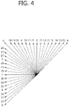
- FIG. 4 is a diagram illustrating intra prediction modes according to an embodiment of the invention.
- the additional intra prediction mode may be the planar mode.
- the additional intra prediction mode may be the DC mode.
- the additional intra prediction mode may be a vertical mode or a horizontal mode.
- the additional intra prediction mode may be an intra prediction mode having directionality between the two intra prediction modes, or the DC mode or the planar mode.
- the MPM group includes the intra prediction mode and two additional intra prediction modes.
- the two additional intra prediction modes are set to two intra prediction modes neighboring the intra prediction mode.
- the two additional intra prediction modes may be the planar mode and the vertical mode.
- the MPM group includes the intra prediction mode and two additional intra prediction modes.
- the two additional intra prediction modes are determined depending on the intra prediction mode.
- the MPM group includes the DC mode, the planar mode, and the vertical mode.
- the intra prediction mode group indicator indicates the MPM group
- the intra prediction mode indicated by the prediction mode index is selected from the MPM group and the selected intra prediction mode is determined as the intra prediction mode of the current block.
- the intra prediction mode group indicator may be flag information representing whether the intra prediction mode of the current block belongs to the MPM group or a group other than the MPM group.
- the intra prediction module 240 determines the intra prediction mode indicated by the prediction mode index out of the intra prediction modes (hereinafter, referred to as residual intra prediction modes) other than the intra prediction modes belonging to the MPM group as the intra prediction mode of the current block.
- the prediction mode indices assigned to the residual intra prediction modes vary depending on the configuration of the MPM group. That is, the decoded prediction mode indices indicate indices of the residual intra prediction modes rearranged depending on the configuration of the MPM group. Therefore, the intra prediction module 240 selects the intra prediction mode of the current block from the residual intra prediction modes depending on the decoded prediction mode index and the intra prediction modes belonging to the MPM group.
- the residual intra prediction modes of the current block are rearranged in the mode number order and the intra prediction mode corresponding to the received prediction mode index is selected as the intra prediction mode of the current block.
- the residual intra prediction modes may be rearranged, but the intra prediction mode of the current block may be determined by comparison of the intra prediction mode numbers belonging to the MPM group with the intra prediction mode index of the current block.
- This method can be applied to a case where mode number 2 is assigned to the DC mode of the non-directional modes, mode number 34 is assigned to the planar mode, and directional mode numbers are assigned to the other modes.
- mode number 2 is assigned to the DC mode of the non-directional modes
- mode number 34 is assigned to the planar mode
- directional mode numbers are assigned to the other modes.
- a small mode number for example, mode number 0
- mode numbers of the other lower-ranked modes increase by 1.
- the lowest indices may be assigned to the non-directional modes.
- the intra prediction mode index may include 0.
- the intra prediction mode corresponding to the prediction mode index in a state where the planar mode, the DC mode, and the directional modes are arranged in this order may be set as the intra prediction mode of the current block.
- mode number 0 and mode number 1 may be assigned to the planar mode the DC mode, respectively, or mode number 0 and mode number 1 may be assigned to the DC mode and the planar mode, respectively.
- the intra prediction mode index of the current block may be compared with the intra prediction mode numbers belonging to the MPM group to determine the intra prediction mode of the current block.
- the size of the prediction block is determined using information indicating the transform size of the current block (S130).
- the prediction block is created using the intra prediction mode of the current block and the reference pixels of the current block.
- the reference pixels are pixels reconstructed or created previously to the current block.
- the same intra prediction mode (that is, the intra prediction mode of the current block) is used to create the prediction block of each sub block.
- the prediction blocks of the second sub block or sub blocks subsequent thereto in the decoding order are created using the reconstructed pixels of the preceding sub blocks. Therefore, after the prediction block, the residual block, and the reconstructed block are created in the units of sub blocks, the prediction block of the next sub block is created.
- the reference pixels are pixels which are previously decoded and reconstructed. When it is determined that at least one of the reference pixels is not valid, the reference pixel is created (S150).
- the reference pixel values are replaced with values of 2 L-1 .
- L represents the number of bits representing the gray scale of luma components.
- the closest reference pixel out of the valid reference pixels is copied to create the reference pixels.
- the reference pixel located at the closest position in a predetermined direction can be copied or two closest reference pixels in both directions can be averaged to create the reference pixels.
- the reference pixels are adaptively filtered depending on the reconstructed intra prediction mode and the size of the prediction block (S170).
- the reference pixels are not filtered when the intra prediction mode is the DC mode.
- the intra prediction module 240 does not also filter the reference pixels.
- the intra prediction modes are directional modes other than the vertical mode and the horizontal mode
- the reference pixels are adaptively filtered depending on the intra prediction mode and the size of the prediction block.
- the size of the prediction block is 4x4
- the reference pixels are not filtered for the purpose of a decrease in complexity regardless of the intra prediction mode.
- the filtering serves to smooth the variation in pixel value between reference pixels and uses a low-pass filter.
- the low-pass filter may be [1, 2, 1] which is a 3-tap filter or [1, 2, 4, 2, 1] which is a 5-tap filter.
- the size of the prediction block ranges from 8x8 to 32x32
- the reference pixels are filtered in more intra prediction modes with an increase in the size of the prediction block.
- the reference pixels used for the prediction block may be pixels which are adaptively filtered depending on the size of the prediction block and the intra prediction mode.
- the prediction pixels neighboring the reference pixels can be created using weighted average of the average value and the reference pixel neighboring the prediction pixel.
- the prediction pixels can be created in the same was as in the DC mode.
- the reference pixels located in the vertical direction are set to the prediction pixels.
- the prediction pixel neighboring the left reference pixel can be created using the reference pixel located in the vertical direction and the variation between the left reference pixels.
- the variation represents the variation between the corner reference pixel and the left reference pixel neighboring the prediction pixel.
- the prediction pixels can be created in the same way as in the vertical mode, except for the direction.
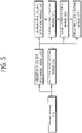
- FIG. 5 is a block diagram illustrating an intra prediction block creating unit 300
- the intra prediction block creating unit 300 includes a parsing module 310, a prediction mode decoding module 320, a prediction block size determining module 330, a reference pixel validity determining module 340, a reference pixel creating module 350, a reference pixel filtering module 360, a prediction block creating module 370.
- the parsing module 310 entropy-decodes a received bit stream to acquired intra prediction information and transform block size information.
- the intra prediction information includes an intra prediction mode group indicator and a prediction mode index.
- the intra prediction mode group indicator represents which of an MPM group and a group other than the MPM group the intra prediction mode of a current block belongs to.
- the prediction mode index is information representing a specific intra prediction mode in the intra prediction mode group indicated by the intra prediction mode group indicator. The method of entropy-decoding the intra prediction information is the same as in step S110 of FIG. 3 .
- the transform block size information includes at least one flag (split_transform_flag) which represents the transform block size and which is transmitted from an encoder.
- the prediction mode decoding module 320 creates an MPM group using the intra prediction modes of blocks neighboring a current block and reconstructs the intra prediction mode of the current block using the MPM group and the entropy-decoded intra prediction information.
- the MPM group includes three intra prediction modes.
- the additional intra prediction mode may be the planar mode.
- the additional intra prediction mode may be the DC mode.
- the additional intra prediction mode may be a vertical mode or a horizontal mode.
- the additional intra prediction mode may be an intra prediction mode having directionality between the two intra prediction modes, or the DC mode or the planar mode.
- the MPM group includes the intra prediction mode and two additional intra prediction modes.
- the two additional intra prediction modes are set to two intra prediction modes neighboring the intra prediction mode.
- the two additional intra prediction modes may be the planar mode and the vertical mode.
- the MPM group includes the intra prediction mode and two additional intra prediction modes.
- the two additional intra prediction modes are determined depending on the intra prediction mode.
- the MPM group includes the DC mode, the planar mode, and the vertical mode.
- the intra prediction mode group indicator indicates the MPM group
- the intra prediction mode indicated by the prediction mode index is selected from the MPM group and the selected intra prediction mode is determined as the intra prediction mode of the current block.
- the intra prediction mode group indicator may be flag information representing whether the intra prediction mode of the current block belongs to the MPM group or a group other than the MPM group.
- the intra prediction module 240 determines the intra prediction mode indicated by the prediction mode index out of the intra prediction modes (hereinafter, referred to as residual intra prediction modes) other than the intra prediction modes belonging to the MPM group as the intra prediction mode of the current block.
- the prediction mode indices assigned to the residual intra prediction modes vary depending on the configuration of the MPM group. That is, the decoded prediction mode indices indicate indices of the residual intra prediction modes rearranged depending on the configuration of the MPM group. Therefore, the intra prediction module 240 selects the intra prediction mode of the current block from the residual intra prediction modes depending on the decoded prediction mode index and the intra prediction modes belonging to the MPM group.
- the residual intra prediction modes of the current block are rearranged in the mode number order and the intra prediction mode corresponding to the received prediction mode index is selected as the intra prediction mode of the current block.
- the residual intra prediction modes may be rearranged, but the intra prediction mode of the current block may be determined by comparison of the intra prediction mode numbers belonging to the MPM group with the intra prediction mode index of the current block.
- the MPM group constructing method can be applied to a case where mode number 2 is assigned to the DC mode of the non-directional modes, mode number 34 is assigned to the planar mode, and directional mode numbers are assigned to the other modes.
- mode number 2 is assigned to the DC mode of the non-directional modes
- mode number 34 is assigned to the planar mode
- directional mode numbers are assigned to the other modes.
- a small mode number for example, mode number 0
- mode numbers of the other lower-ranked modes increase by 1.
- the lowest indices may be assigned to the non-directional modes.
- the intra prediction mode index may include 0.
- the intra prediction mode corresponding to the prediction mode index in a state where the planar mode, the DC mode, and the directional modes are arranged in this order may be set as the intra prediction mode of the current block.
- mode number 0 and mode number 1 may be assigned to the planar mode the DC mode, respectively, or mode number 0 and mode number 1 may be assigned to the DC mode and the planar mode, respectively.
- the intra prediction mode index of the current block may be compared with the intra prediction mode numbers belonging to the MPM group to determine the intra prediction mode of the current block.
- the prediction block size determining module 330 determines the size of the prediction block of the current block using the block transform size.
- the size of the prediction block may have the size of the current block or the size of sub blocks of the current block.
- the prediction block is created using the intra prediction mode of the current block and the reference pixels of the current block.
- the reference pixels are pixels reconstructed or created previously to the current block.
- the same intra prediction mode (that is, the intra prediction mode of the current block) is used to create the prediction block of each sub block.
- the prediction blocks of the second sub block or sub blocks subsequent thereto in the decoding order are created using the reconstructed pixels of the preceding sub blocks. Therefore, after the prediction block, the residual block, and the reconstructed block are created in the units of sub blocks, the prediction block of the next sub block is created.
- the reference pixel validity determining module 340 determines whether the reference pixels of the block corresponding to the size of the prediction block are all valid.
- the reference pixels are pixels which are previously decoded and reconstructed.
- the reference pixel validity determining module 340 creates the reference pixel.
- the reference pixel values are replaced with values of 2 L-1 .
- L represents the number of bits representing the gray scale of luma components.
- the closest reference pixel out of the valid reference pixels is copied to create the reference pixels.
- the reference pixel located at the closest position in a predetermined direction can be copied or two closest reference pixels in both directions can be averaged to create the reference pixels.
- the reference pixel filtering module 360 determines whether the reference pixels should be filtered.
- the reference pixels are adaptively filtered depending on the reconstructed intra prediction mode and the size of the prediction block.
- the reference pixels are not filtered when the intra prediction mode is the DC mode.
- the intra prediction module 240 does not also filter the reference pixels.
- the intra prediction modes are directional modes other than the vertical mode and the horizontal mode
- the reference pixels are adaptively filtered depending on the intra prediction mode and the size of the prediction block.
- the size of the prediction block is 4x4
- the reference pixels are not filtered for the purpose of a decrease in complexity regardless of the intra prediction mode.
- the filtering serves to smooth the variation in pixel value between reference pixels and uses a low-pass filter.
- the low-pass filter may be [1, 2, 1] which is a 3-tap filter or [1, 2, 4, 2, 1] which is a 5-tap filter.
- the size of the prediction block ranges from 8x8 to 32x32
- the reference pixels are filtered in more intra prediction modes with an increase in the size of the prediction block.
- the prediction block creating module 370 creates the prediction block depending on the intra prediction mode.
- the reference pixels used for the prediction block may be pixels which are adaptively filtered depending on the size of the prediction block and the intra prediction mode.
- the prediction pixels neighboring the reference pixels can be created using weighted average of the average value and the reference pixel neighboring the prediction pixel.
- the prediction pixels can be created in the same was as in the DC mode.
- the reference pixels located in the vertical direction are set to the prediction pixels.
- each prediction pixel neighboring the left reference pixel can be created using the reference pixel located in the vertical direction and the variation between the left reference pixels.
- the variation represents the variation between the corner reference pixel and the left reference pixel neighboring the prediction pixel.
- the prediction pixels can be created in the same way as in the vertical mode, except for the direction.
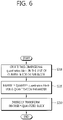
- FIG. 6 is a block diagram illustrating a residual block reconstructing sequence according to the embodiment of the invention.
- a residual signal received in the unit of a current block or a sub block is decoded to create a two-dimensional quantization block (S210).
- the quantization block is inversely quantized using a quantization parameter (S220).
- the inversely-quantized block is inversely transformed to reconstruct a residual block (S230).
- FIG. 7 is a block diagram illustrating a quantization parameter reconstructing sequence according to the embodiment of the invention.
- the quantization parameter reconstructing sequence can be performed by the inverse quantization unit 220 shown in FIG. 2 .
- a minimum CU size (hereinafter, referred to as a minimumminimum quantization CU size) enabling changing of the quantization parameter is reconstructed (S310).
- the minimum quantization CU size can be signaled using one of the following methods.
- a QP should be changed in the unit of LCU or can be additionally changed in a sub CU thereof can be indicated using cu_qp_delta_enabled_flag included in a sequence parameter set.
- cu_qp_delta_enabled_flag included in a sequence parameter set.
- the minimum quantization CU size is signaled using one information piece (cu_qp_delta_depth) through joint coding instead of transmitting both cu_qp_delta_enabled_flag and max_cu_qp_delta_depth. That is, information related to the minimum quantization CU size is not transmitted from the sequence parameter set, but the minimum quantization CU size is transmitted using cu_qp_delta_depth through the picture parameter set. Accordingly, it is possible to reduce the number bits required to transmit the information on the minimum quantization CU size and to adaptively adjust the size enabling changing of the quantization parameter by PPS, thereby improving encoding performance.
- a quantization parameter predictor is calculated on the basis of the minimum quantization CU size (S320).
- the quantization parameter predictor can be created using the left quantization parameter of the current CU and the top quantization parameter of the current CU. For example, the average value of the left quantization parameter and the top quantization parameter can be set as the quantization parameter predictor.
- the quantization parameter predictor and the received residual quantization parameter are added to reconstruct the quantization parameter (S330).
- the quantization parameter of the current CU is reconstructed.
- plural CUs included in the minimum quantization CU size have the same quantization parameter.
Description
- The present invention relates to an image decoding device, and more particularly, to a device that uses quantization parameters of left and top coding units to derive a quantization parameter predictor used for generating a residual block.
- Image data has to be encoded to efficiently store or transmit the image data. MPEG-1, MPEG-2, MPEG-4, H.264/MPEG-4 AVC (Advanced Video Coding), and the like are known as techniques of encoding image data. In these techniques, a picture is divided into macro blocks, it is determined which of intra encoding or inter encoding should be performed in the unit of the macro blocks, and the macro blocks are encoded using the determined encoding method.
- In H.264 which is a latest image compressing technique, intra prediction is performed to enhance the efficiency of the intra encoding. That is, instead of referring to a reference picture to encode a current block, a prediction block is created using pixel values spatially neighboring the current block to be encoded. Specifically, an intra prediction mode having a small distortion is selected through comparison with an original macro block using the neighboring pixel values and the prediction block of the current block to be encoded is created using the selected intra prediction mode and the neighboring pixel values. A residual block including difference signals between the current block and the prediction block is created and the residual block is transformed, quantized, and entropy-encoded. The intra prediction mode used to create the prediction block is also encoded.
- However, in H.264, the intra prediction mode of a current block is encoded regardless of directivity of the intra prediction modes of the left and top blocks of the current block and there is thus a problem in that the encoding efficiency is low. When the number of intra prediction modes increases to enhance the encoding efficiency of a residual block, there is a need for an intra prediction encoding method having efficiency higher than that of the intra prediction mode encoding method of H.264.
- When coding units having various sizes are allowed unlike in H.264, a quantization parameter can be adaptively changed to improve encoding efficiency of a texture. However, in this case, a large number of bits are required to transmitting the quantization parameter. Therefore, there is a need for a method capable of effectively reducing the number of bits.
Weigand T et al; "Overview of the H.264/AVC video coding standard", IEEE Transactions on Circuits and Systems for Video Technology; IEEE Service Center, Piscataway, NJ, US, discloses the video coding standard of the ITU-T Video Coding Experts Group and the ISO/IEC Moving Picture Experts Group. Kobayashi M et al: "CE4 Subtest 2: Delta QP Prediction Results of Test 2.2.b and 2.3.f", 97. MPEG Meeting: 18-7-2011 - 22-7-2011; Torino; (Motion Picture Expert Group of ISO/EIC JTC1/SC29/WG11), no. m20721, 1 July 2011 discloses the experimental results of QP prediction techniques based on CU depth and prediction modes, which are test 2.2.b and test 2.3.f of CE4 Subtest2. These technologies were originally presented in the contribution of JCTVC-E198 at the 5th JCT-VC meeting, and they introduced depth-dependent QP prediction (2.2.b) and the prediction mode dependent QP prediction (2.3.f) respectively.
T-D Chuang et al: "Luma Intra Prediction Mode Coding", 6. JCT-VC Meeting; 97. MPEG Meeting; 14-7-2011 - 22-7-2011; Torino; (Joint Collaborative Team on Video Coding of ISO/IEC JCT1/SC29/WG11 and ITU-T SG. 16), no. JCTVC-F062, 1 July 2011 discloses a luma intra prediction mode coding method. As in IIM-3.0, a current intra prediction mode was first checked to see if it is equal to a most probable mode (MPM) derived from its left block and upper block. When the current intra prediction mode was not equal to any MPM, at most three most probable remaining modes (MPRMs) according to the intra modes of neighboring blocks could be used. When the current intra prediction mode is not equal to any MPM or MPRM, one of the remaining nodes was signaled to indicate the current intra prediction mode. Simulation results reportedly showed 0.4% bit rate reduction in the high efficiency all intra condition with 2% encoding time increase and 1% decoding time increase.
It is therefore the object of the invention to provide an improved reconstructed block creating method.
This object is solved by the subject matter of the independent claim.
Preferred embodiments are defined by the dependent claims. - There is provided an image decoding device including: an intra prediction module for reconstructing an intra prediction mode and creating a prediction block of a current block or a sub block of the current block; an inverse scanning module for converting residual signals into a two-dimensional quantization block; an inverse quantization module for inversely quantizing the quantization block using the quantization parameter; and an inverse transform module for inversely-transforming the inversely-quantized block. A quantization parameter predictor used for deriving the quantization parameter is created using a quantization parameter of a left coding unit of a current coding unit and a quantization parameter of a top coding unit of the current coding unit.
- In the image decoding device, the quantization parameter is reconstructed by adding the quantization parameter predictor to a received residual quantization parameter, and the quantization parameter predictor is set as an average value of the quantization parameter of the left coding unit and the quantization parameter of the top coding unit.
- In the image decoding device, the intra prediction module constructs an MPM group including three intra prediction modes using intra prediction modes of a left and top blocks of the current block, and reconstructs the intra prediction mode of the current block using the MPM group and a received intra prediction information. Also, the MPM group includes a planar mode, a DC mode and a vertical mode when the intra prediction modes of the left and the top block of the current block are invalid.
- The image decoding device includes an intra prediction module for reconstructing an intra prediction mode and creating a prediction block of a current block or a sub block of the current block, an inverse scanning module for converting residual signals into a two-dimensional quantization block, an inverse quantization module for inversely quantizing the quantization block using the quantization parameter, and an inverse transform module for inversely-transforming the inversely-quantized block. A quantization parameter predictor used for deriving the quantization parameter is created using a quantization parameter of a left coding unit of a current coding unit and a quantization parameter of a top coding unit of the current coding unit.
- Therefore, it is possible to improve image quality by adaptively adjusting a quantization parameter of a current block depending on the size of a coding unit and to enhance compression efficiency of an image by effectively encoding/decoding the quantization parameter to reduce the number of bits required for transmitting the quantization parameter.
-
-
FIG. 1 is a block diagram illustrating a moving image encoding device. -
FIG. 2 is a block diagram illustrating a moving image decoding device according to the embodiment of the invention. -
FIG. 3 is a diagram illustrating a method of creating an intra prediction block in the moving image decoding device. -
FIG. 4 is a conceptual diagram illustrating intra prediction modes. -
FIG. 5 is a block diagram illustrating an intra prediction block creating unit 300. -
FIG. 6 is a block diagram illustrating a residual block reconstructing sequence. -
FIG. 7 is a block diagram illustrating a residual block reconstructing sequence. - Hereinafter, various examples of the invention will be described in detail with reference to the accompanying drawings. In description of the invention with reference to the drawings, like constituents are referenced by like reference numerals.
- A moving image encoding device and a moving image decoding device may be user terminals such as a personal computer, a notebook PC, a personal digital assistant, a portable multimedia player, a smart phone, a wireless communication terminal, and a TV or servers providing services. The moving image encoding device and the moving image decoding device may be apparatuses having a communication device such as a communication modem for communicating with various apparatuses or wireless or wired communication networks, a memory storing various programs and data for encoding and decoding an image, and a microprocessor performing the programs to perform operations and controls.
-
FIG. 1 is a block diagram illustrating a moving image encoding device - The moving image encoding device 100 includes an
intra prediction module 110, aninter prediction module 120, a transform andquantization module 130, anentropy encoding module 140, an inverse quantization andinverse transform module 150, apost-processing module 160, apicture buffer 170, a subtraction module 190, and an addition module 195. - The
intra prediction module 110 creates an intra prediction block using reconstructed pixels of a picture or slice to which a current block belongs. Theintra prediction module 110 selects one of a predetermined number of intra prediction modes depending on the size of the current block to be prediction-encoded and creates a prediction block depending on the selected intra prediction mode. - The
inter prediction module 120 performs a motion estimation operation using reference pictures stored in thepicture buffer 170 and determines reference picture indices and motion vectors for the motion estimation operation. Then, theinter prediction module 120 creates an inter prediction block of the current block using the reference picture indices and the motion vectors. - The transform and
quantization module 130 transforms and quantizes a residual block of the prediction block created by theintra prediction module 110 or theinter prediction module 120. The transform is performed using one-dimensional transform matrixes in the horizontal and vertical directions. The residual block for intra prediction is transformed using transform matrixes determined depending on the size of the transform block (that is, the size of the residual block) and the intra prediction mode. The residual block for inter prediction is transformed using predetermined transform matrixes. - The transform and
quantization module 130 quantizes the transform block using a quantization step size. The quantization step size can be changed by coding units equal to or larger than a predetermined size. - The quantized transform block is supplied to the inverse quantization and
inverse transform module 150 and theentropy encoding module 140. - The inverse quantization and
inverse transform module 150 inversely quantizes the quantized transform block and inversely transform the inversely-quantized transform block to reconstruct the residual block. The addition module adds the residual block reconstructed by the inverse quantization andinverse transform module 150 and the prediction block from theintra prediction module 110 or theinter prediction module 120 to creates a reconstructed block. - The
post-processing module 160 serves to improve image quality of the reconstructed picture and includes a deblocking filter module 161, an offset module 162, and a loop filter module 163. - The deblocking filter module 161 adaptively applies a deblocking filter to boundaries of the prediction block and the transform block. The boundaries can be limited to boundaries of 8x8 grids. The deblocking filter module 161 determines the boundaries to be filtered, determines boundary strengths thereof, and determines whether the deblocking filter should be applied to the boundaries when the boundary strength is larger than 0. When it is determined that the boundaries should be filtered, the deblocking filter module 161 selects a filter to be applied to the boundaries and filters the boundaries with the selected filter.
- The offset module 162 determines whether an offset should be applied by pictures or slices so as to reduce the distortion between a pixel in the image undergoing the deblocking filter module and a corresponding original pixel. Alternatively, a slice is divided into plural offset areas and the offset type of each offset area can be determined. The offset type may include a predetermined number of edge offset types and band offset types. When the offset type is an edge offset type, the edge type to which each pixel belongs is determined and an offset corresponding thereto is applied. The edge type is determined on the basis of the distribution of two pixel values neighboring a current pixel.
- The loop filter module 163 adaptively loop-filters the reconstructed image on the basis of the comparison result of the reconstructed image undergoing the offset module 162 with the original image. It is determined whether the reconstructed image should be loop-filtered by coding units. The size and coefficients of the loop filter to be applied may changed by the coding units. Information indicating whether the adaptively loop filter should be applied by coding units may be included in each slice header. In case of a chroma signal, it can be determined whether the adaptive loop filter should be applied by pictures. Therefore, information indicating whether chroma components are filtered may be included in a slice header or a picture header.
- The
picture buffer 170 receives post-processed image data from thepost-processing module 160 and reconstructs and stores an image in the unit of pictures. The picture may be an image in the unit of frames or an image in the unit of fields. - The
entropy encoding module 140 entropy-encodes the quantization coefficient information quantized by the transform andquantization module 130, the intra prediction information received from theintra prediction module 140, the motion information received from theinter prediction unit 150, and the like. Theentropy encoding module 140 includes a scanning module 145 which is used to transform coefficients of the quantized transform block into one-dimensional quantization coefficients. - The scanning module 145 determines a scanning type for transforming the coefficients of the quantized transform block into one-dimensional quantization coefficients. The scanning type may vary depending on a directional intra prediction mode and the size of a transform block. The quantization coefficients are scanned in the backward direction.
- When the quantized transform block is larger than a predetermined size, the transform coefficients are divided into plural sub blocks and are scanned. The scanning types applied to the transform coefficients of the sub blocks are the same. The scanning types applied to the sub blocks may be a zigzag scan or may be the same scanning types as applied to the transform coefficients of the sub blocks.
-
FIG. 2 is a block diagram illustrating a moving image decoding device 200 which may be used in an embodiment of the invention. - The moving image decoding device 200 which may be used in the invention includes an
entropy decoding module 210, aninverse quantization module 220, aninverse transform module 230, anintra prediction module 240, aninter prediction module 250, apost-processing module 260, apicture buffer 270, and anaddition module 280. - The
entropy decoding module 210 decodes a received bit stream and separates the bit stream into intra prediction information, inter prediction information, quantization coefficient information, and the like therefrom. Theentropy decoding module 210 supplies the decoded intra prediction information to theintra prediction module 240 and supplies the decoded inter prediction information to theinter prediction module 250. Theentropy decoding module 210 includes an inverse scanning module 215 for inversely scanning the decoded quantization coefficient information. - The inverse scanning module 215 converts the quantization coefficient information into a two-dimensional quantization block. One of plural scanning types is selected for the conversion. The scanning type may vary depending on a directional intra prediction mode and the size of a transform block. The quantization coefficients are scanned in the backward direction. When the quantized transform block is larger than a predetermined size, the transform coefficients are divided into plural sub blocks and are scanned. The scanning types applied to the transform coefficients of the sub blocks are the same. The scanning types applied to the sub blocks may be a zigzag scan or may be the same scanning types as applied to the transform coefficients of the sub blocks.
- The
inverse quantization module 220 determines a quantization step size predictor of a current coding unit and adds the determined quantization step size predictor to the received residual quantization step size to reconstruct the quantization step size of the current coding unit. Theinverse quantization module 220 inversely quantizes the quantization block using the quantization step size and the inverse quantization matrix. The quantization matrix is determined depending on the size of the quantization block and the prediction mode. That is, the quantization matrixis selected on the basis of at least one of the prediction mode of the current block and the intra prediction modes for the quantization block having a predetermined size. - The
inverse transform module 230 inversely transforms the inversely-quantized transform block to reconstruct a residual block. The inverse transform matrix to be applied to the inverse quantization block can be determined depending on the prediction mode and the intra prediction mode. - The
addition module 280 adds the prediction block created by theintra prediction module 240 or theinter prediction module 250 to the residual block reconstructed by theinverse transform module 230 to create a reconstructed block. - The
intra prediction module 240 reconstructs the intra prediction mode of the current block on the basis of the intra prediction information received from theentropy decoding module 210. Then, theintra prediction module 240 creates a prediction block depending on the reconstructed intra prediction mode. - The
inter prediction module 250 reconstructs the reference picture index and the motion vector on the basis of the inter prediction information received from theentropy decoding module 210. Then, theinter prediction module 250 creates a prediction block of the current block using the reference picture index and the motion vector. When motion compensation with decimal prediction is applied, the selected interpolation filter is applied to create the prediction block. - The operation of the
post-processing module 260 is the same as the operation of thepost-processing module 160 shown inFIG. 1 and thus will not be described again. - The
picture buffer 270 stores the decoded image post-processed by thepost-processing module 260 in the unit of pictures. -
FIG. 3 is a diagram illustrating a method of creating an intra prediction block according to the embodiment of the invention. - First, the intra prediction information from the received bit stream is entropy-decoded (S110).
- The intra prediction information includes the intra prediction mode group indicator and the prediction mode index. The intra prediction mode group indicator indicates whether the intra prediction mode of the current block belongs to an MPM group or a group other than the MPM group. The prediction mode index is information indicating a specific intra prediction mode in the intra prediction mode group indicated by the intra prediction mode group indicator.
- The intra prediction mode group indicator can be received in the form of unsigned integer. In this case, the intra prediction mode group indicator can be used without being entropy-decoded. Alternatively, the intra prediction mode group indicator may be adaptively entropy-encoded depending on the type of a current slice. For example, the intra prediction mode group indicator may be entropy-encoded using contexts determined depending on the slice type. Therefore, the intra prediction mode group indicator may be decoded using the contexts determined depending on the type of the current slice. The entropy-encoding method of the prediction mode index varies depending whether the intra prediction mode belongs to the MPM group or not. Therefore, the prediction mode index is entropy-decoded using different methods. Specifically, when the intra prediction mode group indicator represents that the intra prediction mode of the current block belongs to the MPM group, the prediction mode index is binarized in a truncated Exp-Golomb code manner or a truncated unary manner and is then entropy-encoded. Therefore, after the binary information is acquired by performing the entropy decoding, the prediction mode index is reconstructed using the above-mentioned methods. When the intra prediction mode group indicator represents that the intra prediction mode of the current block does not belong to the MPM group, the prediction mode index can be binarized with a fixed length. Therefore, after the binary information is acquired by performing the entropy decoding, the prediction mode index can be reconstructed.
- Then, the MPM group is created using the intra prediction modes of the blocks neighboring the current block and then the intra prediction mode of the current block is reconstructed using the MPM group (S120). The MPM group includes three intra prediction modes. This will be described with reference to
FIG. 4. FIG. 4 is a diagram illustrating intra prediction modes according to an embodiment of the invention. - (1) When the intra prediction modes of the top and left blocks of a current block are both present and are different from each other, the MPM group includes the two intra prediction modes and one additional intra prediction mode.
- When one of the two intra prediction modes is a DC mode and the other is not a planar mode, the additional intra prediction mode may be the planar mode. Similarly, when one of the two intra prediction modes is the planar mode and the other is not the DC mode, the additional intra prediction mode may be the DC mode.
- When the two intra prediction modes are the DC mode and the planar mode, the additional intra prediction mode may be a vertical mode or a horizontal mode.
- When the two intra prediction modes are not the DC mode nor the planar mode, the additional intra prediction mode may be an intra prediction mode having directionality between the two intra prediction modes, or the DC mode or the planar mode.
- (2) When the intra prediction modes of the top and left blocks of the current block are both present and are equal to each other, the MPM group includes the intra prediction mode and two additional intra prediction modes.
- When the intra prediction mode is neither the DC mode nor the planar mode, the two additional intra prediction modes are set to two intra prediction modes neighboring the intra prediction mode. When the intra prediction mode is the DC mode, the two additional intra prediction modes may be the planar mode and the vertical mode.
- (3) When only one of the intra prediction modes of the top and left blocks of the current block is present, the MPM group includes the intra prediction mode and two additional intra prediction modes. The two additional intra prediction modes are determined depending on the intra prediction mode.
- (4) When the intra prediction modes of the top and left blocks of the current block are not present at all, the MPM group includes the DC mode, the planar mode, and the vertical mode.
- When the intra prediction mode group indicator indicates the MPM group, the intra prediction mode indicated by the prediction mode index is selected from the MPM group and the selected intra prediction mode is determined as the intra prediction mode of the current block. The intra prediction mode group indicator may be flag information representing whether the intra prediction mode of the current block belongs to the MPM group or a group other than the MPM group.
- When the intra prediction mode group indicator does not indicates the MPM group, the
intra prediction module 240 determines the intra prediction mode indicated by the prediction mode index out of the intra prediction modes (hereinafter, referred to as residual intra prediction modes) other than the intra prediction modes belonging to the MPM group as the intra prediction mode of the current block. The prediction mode indices assigned to the residual intra prediction modes vary depending on the configuration of the MPM group. That is, the decoded prediction mode indices indicate indices of the residual intra prediction modes rearranged depending on the configuration of the MPM group. Therefore, theintra prediction module 240 selects the intra prediction mode of the current block from the residual intra prediction modes depending on the decoded prediction mode index and the intra prediction modes belonging to the MPM group. - Specifically, the residual intra prediction modes of the current block are rearranged in the mode number order and the intra prediction mode corresponding to the received prediction mode index is selected as the intra prediction mode of the current block. In this case, the residual intra prediction modes may be rearranged, but the intra prediction mode of the current block may be determined by comparison of the intra prediction mode numbers belonging to the MPM group with the intra prediction mode index of the current block.
- This method can be applied to a case where mode number 2 is assigned to the DC mode of the non-directional modes, mode number 34 is assigned to the planar mode, and directional mode numbers are assigned to the other modes. However, since the probability of selecting the planar mode and the DC mode as the intra prediction mode of the current is higher than those of the other directional modes, a small mode number (for example, mode number 0) is assigned to the planar mode and the above-mentioned method can be applied. In this case, the mode numbers of the other lower-ranked modes increase by 1.
- Alternatively, the lowest indices may be assigned to the non-directional modes. For example, when the intra prediction mode of the current block is the planar mode and the residual intra prediction modes include the planar mode, the intra prediction mode index may include 0. For example, when the residual intra prediction modes include the planar mode and the DC mode, the intra prediction mode corresponding to the prediction mode index in a state where the planar mode, the DC mode, and the directional modes are arranged in this order may be set as the intra prediction mode of the current block. For example,
mode number 0 andmode number 1 may be assigned to the planar mode the DC mode, respectively, ormode number 0 andmode number 1 may be assigned to the DC mode and the planar mode, respectively. In this case, the intra prediction mode index of the current block may be compared with the intra prediction mode numbers belonging to the MPM group to determine the intra prediction mode of the current block. - Then, the size of the prediction block is determined using information indicating the transform size of the current block (S130).
- When the size of the prediction block is equal to the size of the current block, the prediction block is created using the intra prediction mode of the current block and the reference pixels of the current block. The reference pixels are pixels reconstructed or created previously to the current block.
- When the size of the prediction block is smaller than the size of the current block, that is, when the current block can be divided into plural sub blocks and the intra prediction is performed thereon, the same intra prediction mode (that is, the intra prediction mode of the current block) is used to create the prediction block of each sub block. The prediction blocks of the second sub block or sub blocks subsequent thereto in the decoding order are created using the reconstructed pixels of the preceding sub blocks. Therefore, after the prediction block, the residual block, and the reconstructed block are created in the units of sub blocks, the prediction block of the next sub block is created.
- Then, it is determined whether the reference pixels of the block corresponding to the size of the prediction block are all valid (S140). The reference pixels are pixels which are previously decoded and reconstructed. When it is determined that at least one of the reference pixels is not valid, the reference pixel is created (S150).
- Specifically, when it is determined that the reference pixels are not valid at all, the reference pixel values are replaced with values of 2L-1. Here, L represents the number of bits representing the gray scale of luma components.
- When valid reference pixels are present in only one direction with respect to the position of the invalid reference pixel, the closest reference pixel out of the valid reference pixels is copied to create the reference pixels.
- When valid reference pixels are present in both directions with respect to the position of the invalid reference pixel, the reference pixel located at the closest position in a predetermined direction can be copied or two closest reference pixels in both directions can be averaged to create the reference pixels.
- Then, it is determined whether the reference pixels should be filtered (S160). The reference pixels are adaptively filtered depending on the reconstructed intra prediction mode and the size of the prediction block (S170).
- The reference pixels are not filtered when the intra prediction mode is the DC mode. When the intra prediction modes are the vertical mode and the horizontal mode, the
intra prediction module 240 does not also filter the reference pixels. However, when the intra prediction modes are directional modes other than the vertical mode and the horizontal mode, the reference pixels are adaptively filtered depending on the intra prediction mode and the size of the prediction block. When the size of the prediction block is 4x4, the reference pixels are not filtered for the purpose of a decrease in complexity regardless of the intra prediction mode. The filtering serves to smooth the variation in pixel value between reference pixels and uses a low-pass filter. The low-pass filter may be [1, 2, 1] which is a 3-tap filter or [1, 2, 4, 2, 1] which is a 5-tap filter. When the size of the prediction block ranges from 8x8 to 32x32, the reference pixels are filtered in more intra prediction modes with an increase in the size of the prediction block. - Then, the prediction block is created depending on the intra prediction mode (S180). The reference pixels used for the prediction block may be pixels which are adaptively filtered depending on the size of the prediction block and the intra prediction mode.
- In the DC mode, the average values of N top reference pixels located at positions of (x=0, ..., N-1, y=-1), M left reference pixels located at positions of (x=1-, y=0, ..., M-1), and the corner pixel located at a position of (x=-1, y=-1) can be determined as the prediction pixels of the prediction block. However, the prediction pixels neighboring the reference pixels can be created using weighted average of the average value and the reference pixel neighboring the prediction pixel. In the planar mode, the prediction pixels can be created in the same was as in the DC mode.
- In the vertical mode, the reference pixels located in the vertical direction are set to the prediction pixels. However, the prediction pixel neighboring the left reference pixel can be created using the reference pixel located in the vertical direction and the variation between the left reference pixels. The variation represents the variation between the corner reference pixel and the left reference pixel neighboring the prediction pixel. In the horizontal mode, the prediction pixels can be created in the same way as in the vertical mode, except for the direction.
-
FIG. 5 is a block diagram illustrating an intra prediction block creating unit 300 The intra prediction block creating unit 300 includes aparsing module 310, a predictionmode decoding module 320, a prediction blocksize determining module 330, a reference pixelvalidity determining module 340, a referencepixel creating module 350, a referencepixel filtering module 360, a predictionblock creating module 370. - The
parsing module 310 entropy-decodes a received bit stream to acquired intra prediction information and transform block size information. - The intra prediction information includes an intra prediction mode group indicator and a prediction mode index. The intra prediction mode group indicator represents which of an MPM group and a group other than the MPM group the intra prediction mode of a current block belongs to. The prediction mode index is information representing a specific intra prediction mode in the intra prediction mode group indicated by the intra prediction mode group indicator. The method of entropy-decoding the intra prediction information is the same as in step S110 of
FIG. 3 . - The transform block size information includes at least one flag (split_transform_flag) which represents the transform block size and which is transmitted from an encoder.
- The prediction
mode decoding module 320 creates an MPM group using the intra prediction modes of blocks neighboring a current block and reconstructs the intra prediction mode of the current block using the MPM group and the entropy-decoded intra prediction information. The MPM group includes three intra prediction modes. - (1) When the intra prediction modes of the top and left blocks of a current block are both present and are different from each other, the MPM group includes the two intra prediction modes and one additional intra prediction mode.
- When one of the two intra prediction modes is a DC mode and the other is not a planar mode, the additional intra prediction mode may be the planar mode. Similarly, when one of the two intra prediction modes is the planar mode and the other is not the DC mode, the additional intra prediction mode may be the DC mode.
- When the two intra prediction modes are the DC mode and the planar mode, the additional intra prediction mode may be a vertical mode or a horizontal mode.
- When the two intra prediction modes are not the DC mode nor the planar mode, the additional intra prediction mode may be an intra prediction mode having directionality between the two intra prediction modes, or the DC mode or the planar mode.
- (2) When the intra prediction modes of the top and left blocks of the current block are both present and are equal to each other, the MPM group includes the intra prediction mode and two additional intra prediction modes.
- When the intra prediction mode is neither the DC mode nor the planar mode, the two additional intra prediction modes are set to two intra prediction modes neighboring the intra prediction mode. When the intra prediction mode is the DC mode, the two additional intra prediction modes may be the planar mode and the vertical mode.
- (3) When only one of the intra prediction modes of the top and left blocks of the current block is present, the MPM group includes the intra prediction mode and two additional intra prediction modes. The two additional intra prediction modes are determined depending on the intra prediction mode.
- (4) When the intra prediction modes of the top and left blocks of the current block are not present at all, the MPM group includes the DC mode, the planar mode, and the vertical mode.
- When the intra prediction mode group indicator indicates the MPM group, the intra prediction mode indicated by the prediction mode index is selected from the MPM group and the selected intra prediction mode is determined as the intra prediction mode of the current block. The intra prediction mode group indicator may be flag information representing whether the intra prediction mode of the current block belongs to the MPM group or a group other than the MPM group.
- When the intra prediction mode group indicator does not indicates the MPM group, the
intra prediction module 240 determines the intra prediction mode indicated by the prediction mode index out of the intra prediction modes (hereinafter, referred to as residual intra prediction modes) other than the intra prediction modes belonging to the MPM group as the intra prediction mode of the current block. The prediction mode indices assigned to the residual intra prediction modes vary depending on the configuration of the MPM group. That is, the decoded prediction mode indices indicate indices of the residual intra prediction modes rearranged depending on the configuration of the MPM group. Therefore, theintra prediction module 240 selects the intra prediction mode of the current block from the residual intra prediction modes depending on the decoded prediction mode index and the intra prediction modes belonging to the MPM group. - Specifically, the residual intra prediction modes of the current block are rearranged in the mode number order and the intra prediction mode corresponding to the received prediction mode index is selected as the intra prediction mode of the current block. In this case, the residual intra prediction modes may be rearranged, but the intra prediction mode of the current block may be determined by comparison of the intra prediction mode numbers belonging to the MPM group with the intra prediction mode index of the current block.
- The MPM group constructing method can be applied to a case where mode number 2 is assigned to the DC mode of the non-directional modes, mode number 34 is assigned to the planar mode, and directional mode numbers are assigned to the other modes. However, since the probability of selecting the planar mode and the DC mode as the intra prediction mode of the current is higher than those of the other directional modes, a small mode number (for example, mode number 0) is assigned to the planar mode and the above-mentioned method can be applied. In this case, the mode numbers of the other lower-ranked modes increase by 1.
- Alternatively, the lowest indices may be assigned to the non-directional modes. For example, when the intra prediction mode of the current block is the planar mode and the residual intra prediction modes include the planar mode, the intra prediction mode index may include 0. For example, when the residual intra prediction modes include the planar mode and the DC mode, the intra prediction mode corresponding to the prediction mode index in a state where the planar mode, the DC mode, and the directional modes are arranged in this order may be set as the intra prediction mode of the current block. For example,
mode number 0 andmode number 1 may be assigned to the planar mode the DC mode, respectively, ormode number 0 andmode number 1 may be assigned to the DC mode and the planar mode, respectively. In this case, the intra prediction mode index of the current block may be compared with the intra prediction mode numbers belonging to the MPM group to determine the intra prediction mode of the current block. - The prediction block
size determining module 330 determines the size of the prediction block of the current block using the block transform size. The size of the prediction block may have the size of the current block or the size of sub blocks of the current block. - When the size of the prediction block is equal to the size of the current block, the prediction block is created using the intra prediction mode of the current block and the reference pixels of the current block. The reference pixels are pixels reconstructed or created previously to the current block.
- When the size of the prediction block is smaller than the size of the current block, that is, when the current block can be divided into plural sub blocks and the intra prediction is performed thereon, the same intra prediction mode (that is, the intra prediction mode of the current block) is used to create the prediction block of each sub block. The prediction blocks of the second sub block or sub blocks subsequent thereto in the decoding order are created using the reconstructed pixels of the preceding sub blocks. Therefore, after the prediction block, the residual block, and the reconstructed block are created in the units of sub blocks, the prediction block of the next sub block is created.
- The reference pixel
validity determining module 340 determines whether the reference pixels of the block corresponding to the size of the prediction block are all valid. The reference pixels are pixels which are previously decoded and reconstructed. - When it is determined that at least one of the reference pixels is not valid, the reference pixel
validity determining module 340 creates the reference pixel. - Specifically, when it is determined that the reference pixels are not valid at all, the reference pixel values are replaced with values of 2L-1. Here, L represents the number of bits representing the gray scale of luma components.
- When valid reference pixels are present in only one direction with respect to the position of the invalid reference pixel, the closest reference pixel out of the valid reference pixels is copied to create the reference pixels.
- When valid reference pixels are present in both directions with respect to the position of the invalid reference pixel, the reference pixel located at the closest position in a predetermined direction can be copied or two closest reference pixels in both directions can be averaged to create the reference pixels.
- The reference
pixel filtering module 360 determines whether the reference pixels should be filtered. The reference pixels are adaptively filtered depending on the reconstructed intra prediction mode and the size of the prediction block. - The reference pixels are not filtered when the intra prediction mode is the DC mode. When the intra prediction modes are the vertical mode and the horizontal mode, the
intra prediction module 240 does not also filter the reference pixels. However, when the intra prediction modes are directional modes other than the vertical mode and the horizontal mode, the reference pixels are adaptively filtered depending on the intra prediction mode and the size of the prediction block. When the size of the prediction block is 4x4, the reference pixels are not filtered for the purpose of a decrease in complexity regardless of the intra prediction mode. The filtering serves to smooth the variation in pixel value between reference pixels and uses a low-pass filter. The low-pass filter may be [1, 2, 1] which is a 3-tap filter or [1, 2, 4, 2, 1] which is a 5-tap filter. When the size of the prediction block ranges from 8x8 to 32x32, the reference pixels are filtered in more intra prediction modes with an increase in the size of the prediction block. - The prediction
block creating module 370 creates the prediction block depending on the intra prediction mode. The reference pixels used for the prediction block may be pixels which are adaptively filtered depending on the size of the prediction block and the intra prediction mode. - In the DC mode, the average values of N top reference pixels located at positions of (x=0, ..., N-1, y=-1), M left reference pixels located at positions of (x=1-, y=0, ..., M-1), and the corner pixel located at a position of (x=-1, y=-1) can be determined as the prediction pixels of the prediction block. However, the prediction pixels neighboring the reference pixels can be created using weighted average of the average value and the reference pixel neighboring the prediction pixel. In the planar mode, the prediction pixels can be created in the same was as in the DC mode.
- In the vertical mode, the reference pixels located in the vertical direction are set to the prediction pixels. However, each prediction pixel neighboring the left reference pixel can be created using the reference pixel located in the vertical direction and the variation between the left reference pixels. The variation represents the variation between the corner reference pixel and the left reference pixel neighboring the prediction pixel. In the horizontal mode, the prediction pixels can be created in the same way as in the vertical mode, except for the direction.
-
FIG. 6 is a block diagram illustrating a residual block reconstructing sequence according to the embodiment of the invention. - A residual signal received in the unit of a current block or a sub block is decoded to create a two-dimensional quantization block (S210).
- The quantization block is inversely quantized using a quantization parameter (S220).
- The inversely-quantized block is inversely transformed to reconstruct a residual block (S230).
-
FIG. 7 is a block diagram illustrating a quantization parameter reconstructing sequence according to the embodiment of the invention. The quantization parameter reconstructing sequence can be performed by theinverse quantization unit 220 shown inFIG. 2 . - A minimum CU size (hereinafter, referred to as a minimumminimum quantization CU size) enabling changing of the quantization parameter is reconstructed (S310).
- The minimum quantization CU size can be signaled using one of the following methods.
- In a first method, whether a QP should be changed in the unit of LCU or can be additionally changed in a sub CU thereof can be indicated using cu_qp_delta_enabled_flag included in a sequence parameter set. When the value of cu_qp_delta_enabled_flag is 1, that is, when the changing of QPy in a CU smaller than the LCU is enabled, the minimum quantization CU size can be signaled using max_cu_qp_delta_depth included in a picture parameter set.
- In a second method, the minimum quantization CU size is signaled using one information piece (cu_qp_delta_depth) through joint coding instead of transmitting both cu_qp_delta_enabled_flag and max_cu_qp_delta_depth. That is, information related to the minimum quantization CU size is not transmitted from the sequence parameter set, but the minimum quantization CU size is transmitted using cu_qp_delta_depth through the picture parameter set. Accordingly, it is possible to reduce the number bits required to transmit the information on the minimum quantization CU size and to adaptively adjust the size enabling changing of the quantization parameter by PPS, thereby improving encoding performance.
- A quantization parameter predictor is calculated on the basis of the minimum quantization CU size (S320). The quantization parameter predictor can be created using the left quantization parameter of the current CU and the top quantization parameter of the current CU. For example, the average value of the left quantization parameter and the top quantization parameter can be set as the quantization parameter predictor.
- The quantization parameter predictor and the received residual quantization parameter are added to reconstruct the quantization parameter (S330).
- When the current CU is equal to or larger than the minimum quantization CU size, the quantization parameter of the current CU is reconstructed. However, when the current CU is smaller than the minimum quantization CU size, plural CUs included in the minimum quantization CU size have the same quantization parameter.
Claims (4)
- A decoding method of creating a reconstructed block, the method comprising:obtaining an intra prediction mode group indicator and a prediction mode index from a received bit stream;decoding an intra prediction mode using the intra prediction mode group indicator, the prediction mode index and a most probable mode, MPM, group, wherein the MPM group is generated using intra prediction modes of left and top blocks of a current block, and the MPM group includes three intra prediction modes;constructing, by an intra prediction module (240), a prediction block using the intra prediction mode and reference pixels;inversely quantizing, by an inverse quantization module (220) , a received residual signal using a quantization parameter to create a quantized block and inversely transforming the quantized block to create a residual block, wherein the quantization parameter is generated by adding a quantization parameter predictor to a residual quantization parameter, and wherein the quantization parameter predictor is created using a quantization parameter of a left coding unit of a current coding unit and a quantization parameter of a top coding unit of the current coding unit; andadding, by an addition module (280) , the prediction block and the residual block to create a reconstructed block, andwherein an intra prediction mode of the current block is determined as an intra prediction mode indicated by the prediction mode index in the MPM group when the intra prediction mode group indicator indicates the MPM group, and the intra prediction mode of the current block is determined out of intra prediction modes other than the three intra prediction modes in the MPM mode group using the three intra prediction modes in the MPM mode group and the prediction mode index when the intra prediction mode group indicator does not indicate the MPM group,wherein when the intra prediction modes of the left and top blocks are not equal to each other and non-directional intra prediction modes, the MPM group includes the intra prediction modes of the left and top blocks and a vertical mode, wherein the non-directional intra prediction mode are a planar mode and a DC mode.
- The reconstructed block creating method according to claim 1, wherein when the intra prediction modes of the left and top blocks are not equal to each other and directional intra prediction modes, the MPM group includes the intra prediction modes of the left and top blocks and a planar mode.
- The reconstructed block creating method according to claim 1, wherein the mode number 0 is assigned to the planar mode.
- The reconstructed block creating method according to claim 1, whether a method of entropy-encoding the prediction mode index varies depending whether the intra prediction mode belongs to the MPM group or not.
Applications Claiming Priority (4)
| Application Number | Priority Date | Filing Date | Title |
|---|---|---|---|
| KR20110108460 | 2011-10-24 | ||
| KR20110108456 | 2011-10-24 | ||
| EP12843637.5A EP2773117B1 (en) | 2011-10-24 | 2012-04-20 | Image decoding apparatus |
| PCT/KR2012/003085 WO2013062198A1 (en) | 2011-10-24 | 2012-04-20 | Image decoding apparatus |
Related Parent Applications (2)
| Application Number | Title | Priority Date | Filing Date |
|---|---|---|---|
| EP12843637.5A Division EP2773117B1 (en) | 2011-10-24 | 2012-04-20 | Image decoding apparatus |
| EP12843637.5A Division-Into EP2773117B1 (en) | 2011-10-24 | 2012-04-20 | Image decoding apparatus |
Publications (3)
| Publication Number | Publication Date |
|---|---|
| EP3402201A1 EP3402201A1 (en) | 2018-11-14 |
| EP3402201B1 true EP3402201B1 (en) | 2022-08-10 |
| EP3402201B8 EP3402201B8 (en) | 2022-09-14 |
Family
ID=48168004
Family Applications (5)
| Application Number | Title | Priority Date | Filing Date |
|---|---|---|---|
| EP18181663.8A Active EP3402199B1 (en) | 2011-10-24 | 2012-04-20 | Image decoding method |
| EP18181670.3A Active EP3402200B1 (en) | 2011-10-24 | 2012-04-20 | Image decoding apparatus |
| EP18181678.6A Active EP3402202B8 (en) | 2011-10-24 | 2012-04-20 | Image decoding apparatus |
| EP18181673.7A Active EP3402201B8 (en) | 2011-10-24 | 2012-04-20 | Image decoding method |
| EP12843637.5A Active EP2773117B1 (en) | 2011-10-24 | 2012-04-20 | Image decoding apparatus |
Family Applications Before (3)
| Application Number | Title | Priority Date | Filing Date |
|---|---|---|---|
| EP18181663.8A Active EP3402199B1 (en) | 2011-10-24 | 2012-04-20 | Image decoding method |
| EP18181670.3A Active EP3402200B1 (en) | 2011-10-24 | 2012-04-20 | Image decoding apparatus |
| EP18181678.6A Active EP3402202B8 (en) | 2011-10-24 | 2012-04-20 | Image decoding apparatus |
Family Applications After (1)
| Application Number | Title | Priority Date | Filing Date |
|---|---|---|---|
| EP12843637.5A Active EP2773117B1 (en) | 2011-10-24 | 2012-04-20 | Image decoding apparatus |
Country Status (18)
| Country | Link |
|---|---|
| US (6) | US9288488B2 (en) |
| EP (5) | EP3402199B1 (en) |
| JP (5) | JP5722506B2 (en) |
| KR (1) | KR20130045155A (en) |
| CN (6) | CN108093261B (en) |
| CY (1) | CY1121422T1 (en) |
| DK (4) | DK3402200T3 (en) |
| ES (5) | ES2927471T3 (en) |
| HR (1) | HRP20190354T1 (en) |
| HU (5) | HUE059717T2 (en) |
| LT (1) | LT2773117T (en) |
| MX (5) | MX2014003541A (en) |
| PL (5) | PL3402200T3 (en) |
| PT (4) | PT2773117T (en) |
| RS (1) | RS58300B1 (en) |
| SI (1) | SI2773117T1 (en) |
| TR (1) | TR201819073T4 (en) |
| WO (1) | WO2013062198A1 (en) |
Families Citing this family (13)
| Publication number | Priority date | Publication date | Assignee | Title |
|---|---|---|---|---|
| KR20110113561A (en) | 2010-04-09 | 2011-10-17 | 한국전자통신연구원 | Method and apparatus for intra prediction encoding and decoding using adaptive filter |
| KR20130050149A (en) * | 2011-11-07 | 2013-05-15 | 오수미 | Method for generating prediction block in inter prediction mode |
| KR102365685B1 (en) | 2015-01-05 | 2022-02-21 | 삼성전자주식회사 | Method for operating of encoder, and devices having the encoder |
| EP3334160A1 (en) * | 2015-11-06 | 2018-06-13 | Huawei Technologies Co., Ltd. | Method and apparatus for de-quantization of transform coefficients, and decoding device |
| CN113810707A (en) | 2016-04-29 | 2021-12-17 | 世宗大学校产学协力团 | Method and apparatus for encoding and decoding image signal |
| EP3509301B1 (en) | 2016-08-31 | 2023-08-09 | KT Corporation | Method and device for processing video signal |
| CN109479144A (en) * | 2016-10-13 | 2019-03-15 | 富士通株式会社 | Image coding/decoding method, device and image processing equipment |
| CN116781899A (en) * | 2016-10-28 | 2023-09-19 | 韩国电子通信研究院 | Video encoding/decoding method and apparatus, and recording medium storing bit stream |
| CN115802033A (en) * | 2016-12-23 | 2023-03-14 | 华为技术有限公司 | System and method for processing bit stream of rectangular video coding block |
| CN117241044A (en) | 2017-05-17 | 2023-12-15 | 株式会社Kt | Method of decoding video and method of encoding video |
| JP6770192B2 (en) * | 2017-06-01 | 2020-10-14 | パナソニック インテレクチュアル プロパティ コーポレーション オブ アメリカPanasonic Intellectual Property Corporation of America | Encoding device, coding method, decoding device and decoding method |
| US11936868B2 (en) | 2018-11-08 | 2024-03-19 | Interdigital Vc Holdings, Inc. | Quantization for video encoding or decoding based on the surface of a block |
| CN112752101B (en) * | 2019-10-29 | 2022-02-22 | 北京新唐思创教育科技有限公司 | Video quality optimization method and device and storage medium |
Family Cites Families (35)
| Publication number | Priority date | Publication date | Assignee | Title |
|---|---|---|---|---|
| US8761252B2 (en) | 2003-03-27 | 2014-06-24 | Lg Electronics Inc. | Method and apparatus for scalably encoding and decoding video signal |
| KR20060109247A (en) * | 2005-04-13 | 2006-10-19 | 엘지전자 주식회사 | Method and apparatus for encoding/decoding a video signal using pictures of base layer |
| TWI347172B (en) | 2004-01-19 | 2011-08-21 | Suntory Holdings Ltd | Beverage comprising fine pulp, production method of same, and edible material for same |
| JP2006005438A (en) * | 2004-06-15 | 2006-01-05 | Sony Corp | Image processor and method thereof |
| KR100654436B1 (en) * | 2004-07-07 | 2006-12-06 | 삼성전자주식회사 | Method for video encoding and decoding, and video encoder and decoder |
| WO2006004331A1 (en) * | 2004-07-07 | 2006-01-12 | Samsung Electronics Co., Ltd. | Video encoding and decoding methods and video encoder and decoder |
| NO322043B1 (en) * | 2004-12-30 | 2006-08-07 | Tandberg Telecom As | Procedure for simplified entropy coding |
| KR20070016663A (en) | 2005-08-04 | 2007-02-08 | 김해광 | Image encoding and reproducing method and apparatus thereof |
| KR100723507B1 (en) | 2005-10-12 | 2007-05-30 | 삼성전자주식회사 | Adaptive quantization controller of moving picture encoder using I-frame motion prediction and method thereof |
| ZA200900032B (en) * | 2006-07-07 | 2010-03-31 | Ericsson Telefon Ab L M | Video data management |
| CA2655970A1 (en) * | 2006-07-07 | 2008-01-10 | Telefonaktiebolaget L M Ericsson (Publ) | Video data management |
| US8331448B2 (en) * | 2006-12-22 | 2012-12-11 | Qualcomm Incorporated | Systems and methods for efficient spatial intra predictabilty determination (or assessment) |
| US8571104B2 (en) * | 2007-06-15 | 2013-10-29 | Qualcomm, Incorporated | Adaptive coefficient scanning in video coding |
| US20090161757A1 (en) * | 2007-12-21 | 2009-06-25 | General Instrument Corporation | Method and Apparatus for Selecting a Coding Mode for a Block |
| KR101433170B1 (en) * | 2008-01-05 | 2014-08-28 | 경희대학교 산학협력단 | Method of encoding and decoding using the directional information of the prediction mode of the adjacent blocks for estimating the intra prediction mode, and apparatus thereof |
| US8542730B2 (en) | 2008-02-22 | 2013-09-24 | Qualcomm, Incorporated | Fast macroblock delta QP decision |
| CN100596202C (en) * | 2008-05-30 | 2010-03-24 | 四川虹微技术有限公司 | Fast mode selection method in frame |
| KR101306834B1 (en) * | 2008-09-22 | 2013-09-10 | 에스케이텔레콤 주식회사 | Video Encoding/Decoding Apparatus and Method by Using Prediction Possibility of Intra Prediction Mode |
| US8582645B2 (en) | 2009-06-11 | 2013-11-12 | Texas Instruments Incorporated | Reducing flicker in the display of video streams |
| KR101702553B1 (en) | 2009-07-04 | 2017-02-03 | 에스케이 텔레콤주식회사 | Video Coding Method and Apparatus |
| KR101510108B1 (en) | 2009-08-17 | 2015-04-10 | 삼성전자주식회사 | Method and apparatus for encoding video, and method and apparatus for decoding video |
| EP2478702B8 (en) * | 2009-09-14 | 2017-09-06 | Thomson Licensing DTV | Methods and apparatus for efficient video encoding and decoding of intra prediction mode |
| WO2011078562A2 (en) * | 2009-12-21 | 2011-06-30 | 한국전자통신연구원 | Intra-predictive coding and decoding methods, and intra-predictive coding and decoding devices for performing the methods |
| JP4924708B2 (en) | 2009-12-28 | 2012-04-25 | ソニー株式会社 | Decoding apparatus and method |
| CN102754442A (en) * | 2010-02-10 | 2012-10-24 | Lg电子株式会社 | Method and apparatus for processing a video signal |
| US8588303B2 (en) * | 2010-03-31 | 2013-11-19 | Futurewei Technologies, Inc. | Multiple predictor sets for intra-frame coding |
| SI3125555T1 (en) * | 2010-08-17 | 2018-07-31 | M&K Holdings Inc. | Method for encoding an intra prediction mode |
| US20120114034A1 (en) | 2010-11-08 | 2012-05-10 | Mediatek Inc. | Method and Apparatus of Delta Quantization Parameter Processing for High Efficiency Video Coding |
| WO2012122495A1 (en) | 2011-03-10 | 2012-09-13 | Huawei Technologies Co., Ltd. | Using multiple prediction sets to encode extended unified directional intra mode numbers for robustness |
| CN102209243B (en) * | 2011-05-27 | 2012-10-24 | 山东大学 | Depth map intra prediction method based on linear model |
| US9654785B2 (en) | 2011-06-09 | 2017-05-16 | Qualcomm Incorporated | Enhanced intra-prediction mode signaling for video coding using neighboring mode |
| KR20110111339A (en) * | 2011-08-23 | 2011-10-11 | 한국전자통신연구원 | Apparatus and method for predicting most probable mode in intra prediction system |
| GB2494468B (en) * | 2011-09-12 | 2014-01-15 | Canon Kk | Method and device for encoding or decoding information representing prediction modes |
| EP2742684B1 (en) | 2011-09-13 | 2018-09-26 | HFI Innovation Inc. | Method and apparatus for intra mode coding in hevc |
| CN103959789B (en) * | 2011-10-07 | 2017-06-06 | 英迪股份有限公司 | Using candidate's intra prediction mode to the method and apparatus of intra prediction mode coding/decoding |
-
2012
- 2012-04-20 PL PL18181670.3T patent/PL3402200T3/en unknown
- 2012-04-20 RS RS20190168A patent/RS58300B1/en unknown
- 2012-04-20 PL PL18181678.6T patent/PL3402202T3/en unknown
- 2012-04-20 PL PL12843637T patent/PL2773117T3/en unknown
- 2012-04-20 PT PT12843637T patent/PT2773117T/en unknown
- 2012-04-20 DK DK18181670.3T patent/DK3402200T3/en active
- 2012-04-20 CN CN201810105494.8A patent/CN108093261B/en active Active
- 2012-04-20 PL PL18181663T patent/PL3402199T3/en unknown
- 2012-04-20 PT PT181816737T patent/PT3402201T/en unknown
- 2012-04-20 ES ES18181678T patent/ES2927471T3/en active Active
- 2012-04-20 KR KR20120041381A patent/KR20130045155A/en not_active Application Discontinuation
- 2012-04-20 CN CN201810105492.9A patent/CN108093260B/en active Active
- 2012-04-20 HU HUE18181673A patent/HUE059717T2/en unknown
- 2012-04-20 MX MX2014003541A patent/MX2014003541A/en active IP Right Grant
- 2012-04-20 ES ES18181663T patent/ES2789198T3/en active Active
- 2012-04-20 DK DK12843637.5T patent/DK2773117T3/en active
- 2012-04-20 CN CN201810105702.4A patent/CN108174213B/en active Active
- 2012-04-20 EP EP18181663.8A patent/EP3402199B1/en active Active
- 2012-04-20 MX MX2015015072A patent/MX338989B/en unknown
- 2012-04-20 JP JP2014531703A patent/JP5722506B2/en active Active
- 2012-04-20 PL PL18181673.7T patent/PL3402201T3/en unknown
- 2012-04-20 WO PCT/KR2012/003085 patent/WO2013062198A1/en active Application Filing
- 2012-04-20 EP EP18181670.3A patent/EP3402200B1/en active Active
- 2012-04-20 EP EP18181678.6A patent/EP3402202B8/en active Active
- 2012-04-20 ES ES12843637T patent/ES2710214T3/en active Active
- 2012-04-20 PT PT181816703T patent/PT3402200T/en unknown
- 2012-04-20 ES ES18181670T patent/ES2935823T3/en active Active
- 2012-04-20 HU HUE18181678A patent/HUE060005T2/en unknown
- 2012-04-20 MX MX2015015069A patent/MX338988B/en unknown
- 2012-04-20 MX MX2015015076A patent/MX338990B/en unknown
- 2012-04-20 DK DK18181678.6T patent/DK3402202T3/en active
- 2012-04-20 LT LTEP12843637.5T patent/LT2773117T/en unknown
- 2012-04-20 CN CN201810105690.5A patent/CN108111848B/en active Active
- 2012-04-20 SI SI201231502T patent/SI2773117T1/en unknown
- 2012-04-20 HU HUE12843637A patent/HUE041726T2/en unknown
- 2012-04-20 TR TR2018/19073T patent/TR201819073T4/en unknown
- 2012-04-20 US US14/124,576 patent/US9288488B2/en not_active Expired - Fee Related
- 2012-04-20 ES ES18181673T patent/ES2928699T3/en active Active
- 2012-04-20 CN CN201280047349.XA patent/CN103931186B/en active Active
- 2012-04-20 MX MX2015015066A patent/MX339135B/en unknown
- 2012-04-20 EP EP18181673.7A patent/EP3402201B8/en active Active
- 2012-04-20 EP EP12843637.5A patent/EP2773117B1/en active Active
- 2012-04-20 HU HUE18181663A patent/HUE050655T2/en unknown
- 2012-04-20 DK DK18181673.7T patent/DK3402201T3/en active
- 2012-04-20 HU HUE18181670A patent/HUE060890T2/en unknown
- 2012-04-20 CN CN201810105701.XA patent/CN108093262B/en active Active
- 2012-04-20 PT PT181816786T patent/PT3402202T/en unknown
-
2015
- 2015-03-25 JP JP2015061971A patent/JP5989838B2/en active Active
- 2015-03-25 JP JP2015061973A patent/JP5989840B2/en active Active
- 2015-03-25 JP JP2015061972A patent/JP5989839B2/en active Active
- 2015-03-25 JP JP2015061974A patent/JP5989841B2/en active Active
-
2016
- 2016-02-25 US US15/053,797 patent/US10523941B2/en active Active
- 2016-02-25 US US15/053,801 patent/US10587877B2/en active Active
- 2016-02-25 US US15/053,814 patent/US10523942B2/en active Active
- 2016-02-25 US US15/053,821 patent/US10523943B2/en active Active
-
2019
- 2019-01-07 CY CY20191100013T patent/CY1121422T1/en unknown
- 2019-02-22 HR HRP20190354TT patent/HRP20190354T1/en unknown
-
2020
- 2020-02-04 US US16/781,624 patent/US11785218B2/en active Active
Also Published As
Similar Documents
| Publication | Publication Date | Title |
|---|---|---|
| US11206397B2 (en) | Reconstructed block creating method | |
| US11785218B2 (en) | Image decoding apparatus | |
| EP2942956B1 (en) | Image decoding apparatus | |
| EP2950535B1 (en) | Method and apparatus for decoding intra prediction mode | |
| US9961343B2 (en) | Method and apparatus for generating reconstructed block |
Legal Events
| Date | Code | Title | Description |
|---|---|---|---|
| PUAI | Public reference made under article 153(3) epc to a published international application that has entered the european phase |
Free format text: ORIGINAL CODE: 0009012 |
|
| STAA | Information on the status of an ep patent application or granted ep patent |
Free format text: STATUS: THE APPLICATION HAS BEEN PUBLISHED |
|
| AC | Divisional application: reference to earlier application |
Ref document number: 2773117 Country of ref document: EP Kind code of ref document: P |
|
| AK | Designated contracting states |
Kind code of ref document: A1 Designated state(s): AL AT BE BG CH CY CZ DE DK EE ES FI FR GB GR HR HU IE IS IT LI LT LU LV MC MK MT NL NO PL PT RO RS SE SI SK SM TR |
|
| STAA | Information on the status of an ep patent application or granted ep patent |
Free format text: STATUS: REQUEST FOR EXAMINATION WAS MADE |
|
| 17P | Request for examination filed |
Effective date: 20190506 |
|
| RBV | Designated contracting states (corrected) |
Designated state(s): AL AT BE BG CH CY CZ DE DK EE ES FI FR GB GR HR HU IE IS IT LI LT LU LV MC MK MT NL NO PL PT RO RS SE SI SK SM TR |
|
| STAA | Information on the status of an ep patent application or granted ep patent |
Free format text: STATUS: EXAMINATION IS IN PROGRESS |
|
| 17Q | First examination report despatched |
Effective date: 20190731 |
|
| RAP1 | Party data changed (applicant data changed or rights of an application transferred) |
Owner name: INNOTIVE LTD |
|
| STAA | Information on the status of an ep patent application or granted ep patent |
Free format text: STATUS: EXAMINATION IS IN PROGRESS |
|
| GRAP | Despatch of communication of intention to grant a patent |
Free format text: ORIGINAL CODE: EPIDOSNIGR1 |
|
| STAA | Information on the status of an ep patent application or granted ep patent |
Free format text: STATUS: GRANT OF PATENT IS INTENDED |
|
| INTG | Intention to grant announced |
Effective date: 20220228 |
|
| GRAS | Grant fee paid |
Free format text: ORIGINAL CODE: EPIDOSNIGR3 |
|
| GRAA | (expected) grant |
Free format text: ORIGINAL CODE: 0009210 |
|
| STAA | Information on the status of an ep patent application or granted ep patent |
Free format text: STATUS: THE PATENT HAS BEEN GRANTED |
|
| REG | Reference to a national code |
Ref country code: DE Ref legal event code: R081 Ref document number: 602012078604 Country of ref document: DE Owner name: GENSQUARE LLC, KR Free format text: FORMER OWNER: INNOTIVE LTD, LONDON, GB |
|
| AC | Divisional application: reference to earlier application |
Ref document number: 2773117 Country of ref document: EP Kind code of ref document: P |
|
| AK | Designated contracting states |
Kind code of ref document: B1 Designated state(s): AL AT BE BG CH CY CZ DE DK EE ES FI FR GB GR HR HU IE IS IT LI LT LU LV MC MK MT NL NO PL PT RO RS SE SI SK SM TR |
|
| REG | Reference to a national code |
Ref country code: AT Ref legal event code: REF Ref document number: 1511442 Country of ref document: AT Kind code of ref document: T Effective date: 20220815 Ref country code: CH Ref legal event code: EP |
|
| RAP2 | Party data changed (patent owner data changed or rights of a patent transferred) |
Owner name: GENSQUARE LLC |
|
| REG | Reference to a national code |
Ref country code: IE Ref legal event code: FG4D Ref country code: CH Ref legal event code: PK Free format text: BERICHTIGUNG B8 |
|
| REG | Reference to a national code |
Ref country code: DE Ref legal event code: R096 Ref document number: 602012078604 Country of ref document: DE |
|
| REG | Reference to a national code |
Ref country code: PT Ref legal event code: SC4A Ref document number: 3402201 Country of ref document: PT Date of ref document: 20220923 Kind code of ref document: T Free format text: AVAILABILITY OF NATIONAL TRANSLATION Effective date: 20220916 |
|
| REG | Reference to a national code |
Ref country code: RO Ref legal event code: EPE |
|
| REG | Reference to a national code |
Ref country code: SE Ref legal event code: TRGR |
|
| REG | Reference to a national code |
Ref country code: DK Ref legal event code: T3 Effective date: 20221026 |
|
| REG | Reference to a national code |
Ref country code: NO Ref legal event code: T2 Effective date: 20220810 |
|
| REG | Reference to a national code |
Ref country code: NL Ref legal event code: FP |
|
| REG | Reference to a national code |
Ref country code: ES Ref legal event code: FG2A Ref document number: 2928699 Country of ref document: ES Kind code of ref document: T3 Effective date: 20221122 |
|
| REG | Reference to a national code |
Ref country code: SK Ref legal event code: T3 Ref document number: E 40506 Country of ref document: SK |
|
| REG | Reference to a national code |
Ref country code: EE Ref legal event code: FG4A Ref document number: E022820 Country of ref document: EE Effective date: 20221018 |
|
| REG | Reference to a national code |
Ref country code: LT Ref legal event code: MG9D |
|
| REG | Reference to a national code |
Ref country code: HU Ref legal event code: AG4A Ref document number: E059717 Country of ref document: HU |
|
| REG | Reference to a national code |
Ref country code: GR Ref legal event code: EP Ref document number: 20220402193 Country of ref document: GR Effective date: 20221212 |
|
| PG25 | Lapsed in a contracting state [announced via postgrant information from national office to epo] |
Ref country code: RS Free format text: LAPSE BECAUSE OF FAILURE TO SUBMIT A TRANSLATION OF THE DESCRIPTION OR TO PAY THE FEE WITHIN THE PRESCRIBED TIME-LIMIT Effective date: 20220810 Ref country code: LV Free format text: LAPSE BECAUSE OF FAILURE TO SUBMIT A TRANSLATION OF THE DESCRIPTION OR TO PAY THE FEE WITHIN THE PRESCRIBED TIME-LIMIT Effective date: 20220810 Ref country code: LT Free format text: LAPSE BECAUSE OF FAILURE TO SUBMIT A TRANSLATION OF THE DESCRIPTION OR TO PAY THE FEE WITHIN THE PRESCRIBED TIME-LIMIT Effective date: 20220810 Ref country code: FI Free format text: LAPSE BECAUSE OF FAILURE TO SUBMIT A TRANSLATION OF THE DESCRIPTION OR TO PAY THE FEE WITHIN THE PRESCRIBED TIME-LIMIT Effective date: 20220810 |
|
| PG25 | Lapsed in a contracting state [announced via postgrant information from national office to epo] |
Ref country code: IS Free format text: LAPSE BECAUSE OF FAILURE TO SUBMIT A TRANSLATION OF THE DESCRIPTION OR TO PAY THE FEE WITHIN THE PRESCRIBED TIME-LIMIT Effective date: 20221210 Ref country code: HR Free format text: LAPSE BECAUSE OF FAILURE TO SUBMIT A TRANSLATION OF THE DESCRIPTION OR TO PAY THE FEE WITHIN THE PRESCRIBED TIME-LIMIT Effective date: 20220810 |
|
| PG25 | Lapsed in a contracting state [announced via postgrant information from national office to epo] |
Ref country code: SM Free format text: LAPSE BECAUSE OF FAILURE TO SUBMIT A TRANSLATION OF THE DESCRIPTION OR TO PAY THE FEE WITHIN THE PRESCRIBED TIME-LIMIT Effective date: 20220810 |
|
| PGFP | Annual fee paid to national office [announced via postgrant information from national office to epo] |
Ref country code: RO Payment date: 20230321 Year of fee payment: 12 Ref country code: FR Payment date: 20230309 Year of fee payment: 12 Ref country code: CZ Payment date: 20230329 Year of fee payment: 12 Ref country code: BG Payment date: 20230317 Year of fee payment: 12 |
|
| REG | Reference to a national code |
Ref country code: DE Ref legal event code: R097 Ref document number: 602012078604 Country of ref document: DE |
|
| PGFP | Annual fee paid to national office [announced via postgrant information from national office to epo] |
Ref country code: SK Payment date: 20230313 Year of fee payment: 12 Ref country code: SE Payment date: 20230310 Year of fee payment: 12 Ref country code: PL Payment date: 20230314 Year of fee payment: 12 Ref country code: IT Payment date: 20230310 Year of fee payment: 12 Ref country code: GR Payment date: 20230315 Year of fee payment: 12 Ref country code: GB Payment date: 20230302 Year of fee payment: 12 Ref country code: EE Payment date: 20230306 Year of fee payment: 12 Ref country code: BE Payment date: 20230315 Year of fee payment: 12 |
|
| PLBE | No opposition filed within time limit |
Free format text: ORIGINAL CODE: 0009261 |
|
| STAA | Information on the status of an ep patent application or granted ep patent |
Free format text: STATUS: NO OPPOSITION FILED WITHIN TIME LIMIT |
|
| PG25 | Lapsed in a contracting state [announced via postgrant information from national office to epo] |
Ref country code: AL Free format text: LAPSE BECAUSE OF FAILURE TO SUBMIT A TRANSLATION OF THE DESCRIPTION OR TO PAY THE FEE WITHIN THE PRESCRIBED TIME-LIMIT Effective date: 20220810 |
|
| PGFP | Annual fee paid to national office [announced via postgrant information from national office to epo] |
Ref country code: NL Payment date: 20230314 Year of fee payment: 12 Ref country code: LU Payment date: 20230414 Year of fee payment: 12 |
|
| P01 | Opt-out of the competence of the unified patent court (upc) registered |
Effective date: 20230530 |
|
| 26N | No opposition filed |
Effective date: 20230511 |
|
| PGFP | Annual fee paid to national office [announced via postgrant information from national office to epo] |
Ref country code: PT Payment date: 20230420 Year of fee payment: 12 Ref country code: NO Payment date: 20230412 Year of fee payment: 12 Ref country code: ES Payment date: 20230512 Year of fee payment: 12 Ref country code: DK Payment date: 20230414 Year of fee payment: 12 Ref country code: DE Payment date: 20230307 Year of fee payment: 12 Ref country code: CH Payment date: 20230501 Year of fee payment: 12 |
|
| PG25 | Lapsed in a contracting state [announced via postgrant information from national office to epo] |
Ref country code: SI Free format text: LAPSE BECAUSE OF FAILURE TO SUBMIT A TRANSLATION OF THE DESCRIPTION OR TO PAY THE FEE WITHIN THE PRESCRIBED TIME-LIMIT Effective date: 20220810 |
|
| PGFP | Annual fee paid to national office [announced via postgrant information from national office to epo] |
Ref country code: TR Payment date: 20230417 Year of fee payment: 12 Ref country code: HU Payment date: 20230320 Year of fee payment: 12 Ref country code: AT Payment date: 20230327 Year of fee payment: 12 |
|
| REG | Reference to a national code |
Ref country code: AT Ref legal event code: UEP Ref document number: 1511442 Country of ref document: AT Kind code of ref document: T Effective date: 20220810 |
|
| PG25 | Lapsed in a contracting state [announced via postgrant information from national office to epo] |
Ref country code: MC Free format text: LAPSE BECAUSE OF FAILURE TO SUBMIT A TRANSLATION OF THE DESCRIPTION OR TO PAY THE FEE WITHIN THE PRESCRIBED TIME-LIMIT Effective date: 20220810 |
|
| PG25 | Lapsed in a contracting state [announced via postgrant information from national office to epo] |
Ref country code: MC Free format text: LAPSE BECAUSE OF FAILURE TO SUBMIT A TRANSLATION OF THE DESCRIPTION OR TO PAY THE FEE WITHIN THE PRESCRIBED TIME-LIMIT Effective date: 20220810 |
|
| REG | Reference to a national code |
Ref country code: IE Ref legal event code: MM4A |
|
| PG25 | Lapsed in a contracting state [announced via postgrant information from national office to epo] |
Ref country code: IE Free format text: LAPSE BECAUSE OF NON-PAYMENT OF DUE FEES Effective date: 20230420 |