EP3402104B1 - Verfahren und vorrichtungen zur 3d-modulation mit strahlspringen - Google Patents
Verfahren und vorrichtungen zur 3d-modulation mit strahlspringen Download PDFInfo
- Publication number
- EP3402104B1 EP3402104B1 EP17170858.9A EP17170858A EP3402104B1 EP 3402104 B1 EP3402104 B1 EP 3402104B1 EP 17170858 A EP17170858 A EP 17170858A EP 3402104 B1 EP3402104 B1 EP 3402104B1
- Authority
- EP
- European Patent Office
- Prior art keywords
- transmitters
- modulation symbol
- received modulation
- source
- transmitter
- Prior art date
- Legal status (The legal status is an assumption and is not a legal conclusion. Google has not performed a legal analysis and makes no representation as to the accuracy of the status listed.)
- Not-in-force
Links
Images





Classifications
-
- H—ELECTRICITY
- H04—ELECTRIC COMMUNICATION TECHNIQUE
- H04L—TRANSMISSION OF DIGITAL INFORMATION, e.g. TELEGRAPHIC COMMUNICATION
- H04L27/00—Modulated-carrier systems
- H04L27/26—Systems using multi-frequency codes
- H04L27/2601—Multicarrier modulation systems
- H04L27/2647—Arrangements specific to the receiver only
- H04L27/2649—Demodulators
-
- H—ELECTRICITY
- H04—ELECTRIC COMMUNICATION TECHNIQUE
- H04L—TRANSMISSION OF DIGITAL INFORMATION, e.g. TELEGRAPHIC COMMUNICATION
- H04L27/00—Modulated-carrier systems
- H04L27/26—Systems using multi-frequency codes
- H04L27/2601—Multicarrier modulation systems
- H04L27/2647—Arrangements specific to the receiver only
- H04L27/2655—Synchronisation arrangements
- H04L27/2689—Link with other circuits, i.e. special connections between synchronisation arrangements and other circuits for achieving synchronisation
- H04L27/2695—Link with other circuits, i.e. special connections between synchronisation arrangements and other circuits for achieving synchronisation with channel estimation, e.g. determination of delay spread, derivative or peak tracking
Definitions
- Various embodiments relate generally to methods and devices for 3D modulation with beam hopping.
- constellation-based modulation techniques to transmit data at the physical layer.
- a modulator separates a transmit bit stream into transmit bit vectors of a specific length and then maps each transmit bit vector onto a constellation of points, where each point corresponds to a different transmit bit vector and associated modulation symbol. The modulator then selects the modulation symbol for each transmit bit vector and provides the modulation symbol to the radio circuitry for subsequent transmission as wireless radio signals.
- Constellations with larger numbers of points and modulation symbols can enable higher data rates due to the ability to encode more bits into each transmitted modulation symbol.
- high modulation order may also be more susceptible to noise and interference as the counterpart demodulator may have difficulty in determining which specific point in the correlation corresponds to each received modulation symbol.
- quadrature spatial modulation is a recently proposed multiple-input multiple-output transmission scheme which improves the spectral efficiency of classical spatial modulation (SM) by increasing the number of information bits transmitted by antenna indices.
- SM classical spatial modulation
- a low-complexity, near-maximum likelihood (ML) error performance achieving detection scheme is proposed for QSM to reduce the overall computational complexity of the ML detector.
- the proposed detector determines the set of most probable active transmit antennas and the corresponding possible transmission patterns.
- ML-based detection is used to determine the transmitted complex data vector by performing a search over these transmission patterns and M-ary constellation symbols. It has been shown via computer simulations that the proposed detection algorithm exhibits near-ML bit error rate performance with considerably lower decoding complexity.
- a searching method is developed to obtain the final decision through a trade-off between performance and complexity.
- the equivalence between DBD and ML algorithms is also proved by theoretical analysis.
- a new low-complexity soft output DBD (SODBD) algorithm is developed for coded SM systems.
- the simulation results show that DBD algorithm has a close performance to ML algorithm while effectively reducing the complexity compared to conventional near-ML algorithms.
- US 2003/0038741 A1 describes a system for determining the scan type of a signal, such as a radar signal, includes a scan detector, a transformer (e.g., an FFT algorithm), a correlator, and a decision block.
- the signal is received and processed by the scan detector.
- the scan detector provides an envelope signal, representing the scan type of the received signal.
- the envelope signal is transformed, typically from a time domain signal to a frequency domain signal, by any of several processes including a Fourier transform, a Laplace transform, an FFT, or a DFT.
- the transformed envelope signal is compared to several scan data sets by the correlator. Each scan data set represents a particular scan type. If the decision block determines that the comparison between the transformed envelope signal and a scan data set meets (or exceeds) a degree of similarity, the scan type of the received signal is determined to be the scan type of that scan data set.
- plural and “multiple” in the description or the claims expressly refer to a quantity greater than one.
- group (of)”, “set [of]”, “collection (of)”, “series (of)”, “sequence (of)”, “grouping (of)”, etc., and the like in the description or in the claims refer to a quantity equal to or greater than one, i.e. one or more. Any term expressed in plural form that does not expressly state “plurality” or “multiple” likewise refers to a quantity equal to or greater than one.
- the terms “proper subset”, “reduced subset”, and “lesser subset” refer to a subset of a set that is not equal to the set, i.e. a subset of a set that contains less elements than the set.
- references to a "vector” may refer to a vector of any size or orientation, e.g. including a 1x1 vector (e.g. a scalar), a 1xM vector (e.g. a row vector), and an Mx1 vector (e.g. a column vector).
- a 1x1 vector e.g. a scalar
- a 1xM vector e.g. a row vector
- Mx1 vector e.g. a column vector
- references to a "matrix” may refer to matrix of any size or orientation, e.g. including a 1x1 matrix (e.g. a scalar), a 1xM matrix (e.g. a row vector), and an Mx1 matrix (e.g. a column vector).
- a 1x1 matrix e.g. a scalar
- a 1xM matrix e.g. a row vector
- Mx1 matrix e.g. a column vector
- a “circuit” as used herein is understood as any kind of logic-implementing entity, which may include special-purpose hardware or a processor executing software.
- a circuit may thus be an analog circuit, digital circuit, mixed-signal circuit, logic circuit, processor, microprocessor, Central Processing Unit (CPU), Graphics Processing Unit (GPU), Digital Signal Processor (DSP), Field Programmable Gate Array (FPGA), integrated circuit, Application Specific Integrated Circuit (ASIC), etc., or any combination thereof. Any other kind of implementation of the respective functions which will be described below in further detail may also be understood as a "circuit”.
- circuits may be realized as a single circuit with substantially equivalent functionality, and conversely that any single circuit detailed herein may be realized as two (or more) separate circuits with substantially equivalent functionality.
- references to a "circuit” may refer to two or more circuits that collectively form a single circuit.
- circuit arrangement may refer to a single circuit, a collection of circuits, and/or an electronic device composed of one or more circuits.
- memory may be understood as a non-transitory computer-readable medium in which data or information can be stored for retrieval. References to “memory” included herein may thus be understood as referring to volatile or non-volatile memory, including random access memory (RAM), read-only memory (ROM), flash memory, solid-state storage, magnetic tape, hard disk drive, optical drive, etc., or any combination thereof. Furthermore, it is appreciated that registers, shift registers, processor registers, data buffers, etc., are also embraced herein by the term memory. It is appreciated that a single component referred to as “memory” or “a memory” may be composed of more than one different type of memory, and thus may refer to a collective component comprising one or more types of memory.
- any single memory component may be separated into multiple collectively equivalent memory components, and vice versa.
- memory may be depicted as separate from one or more other components (such as in the drawings), it is understood that memory may be integrated within another component, such as on a common integrated chip.
- terminal device utilized herein refers to user-side devices (both mobile and immobile) that can connect to a core network and various external networks via a radio access network.
- network access node refers to a network-side device that provides a radio access network with which terminal devices can connect and exchange information with other networks through the network access node.
- base station used in reference to an access point of a mobile communication network may be understood as a macro base station, micro base station, Node B, evolved NodeB (eNB), Home eNodeB, Remote Radio Head (RRH), relay point, etc.
- a "cell” in the context of telecommunications may be understood as a sector served by a base station. Accordingly, a cell may be a set of geographically co-located antennas that correspond to a particular sectorization of a base station. A base station may thus serve one or more cells (or sectors), where each cell is characterized by a distinct communication channel.
- cell may be utilized to refer to any of a macrocell, microcell, femtocell, picocell, etc.
- the terms “user equipment”, “UE”, “mobile terminal”, “user terminal”, “terminal device”, etc., may apply to any wireless communication device, including cellular phones, tablets, laptops, personal computers, wearables, multimedia playback and other handheld electronic devices, consumer/home/office/commercial appliances, vehicles, and any number of additional electronic devices capable of wireless communications.
- radio links described herein may operate according to any one or more of the following radio communication technologies and/or standards including but not limited to: a Global System for Mobile Communications (GSM) radio communication technology, a General Packet Radio Service (GPRS) radio communication technology, an Enhanced Data Rates for GSM Evolution (EDGE) radio communication technology, and/or a Third Generation Partnership Project (3GPP) radio communication technology, for example Universal Mobile Telecommunications System (UMTS), Freedom of Multimedia Access (FOMA), 3GPP Long Term Evolution (LTE), 3GPP Long Term Evolution Advanced (LTE Advanced), Code division multiple access 2000 (CDMA2000), Cellular Digital Packet Data (CDPD), Mobitex, Third Generation (3G), Circuit Switched Data (CSD), High-Speed Circuit-Switched Data (HSCSD), Universal Mobile Telecommunications System (Third Generation) (UMTS (3G)), Wideband Code Division Multiple Access (Universal Mobile Telecommunications System) (W-CDMA (UMTS)), High Speed Packet Access (HSPA), High-Speed Downlink
- 3GPP Rel. 9 (3rd Generation Partnership Project Release 9), 3GPP Rel. 10 (3rd Generation Partnership Project Release 10), 3GPP Rel. 11 (3rd Generation Partnership Project Release 11), 3GPP Rel. 12 (3rd Generation Partnership Project Release 12), 3GPP Rel. 13 (3rd Generation Partnership Project Release 13), 3GPP Rel. 14 (3rd Generation Partnership Project Release 14), 3GPP Rel. 15 (3rd Generation Partnership Project Release 15), 3GPP Rel. 16 (3rd Generation Partnership Project Release 16), 3GPP Rel. 17 (3rd Generation Partnership Project Release 17), 3GPP Rel.
- Applicable spectrum bands include IMT (International Mobile Telecommunications) spectrum (including 450 - 470 MHz, 790 - 960 MHz, 1710 - 2025 MHz, 2110 - 2200 MHz, 2300 - 2400 MHz, 2500 - 2690 MHz, 698-790 MHz, 610 - 790 MHz, 3400 - 3600 MHz, etc.).
- IMT International Mobile Telecommunications
- IMT-advanced spectrum IMT-2020 spectrum (expected to include 3600-3800 MHz, 3.5 GHz bands, 700 MHz bands, bands within the 24.25-86 GHz range, etc.), spectrum made available under FCC's "Spectrum Frontier" 5G initiative (including 27.5 - 28.35 GHz, 29.1 - 29.25 GHz, 31 - 31.3 GHz, 37 - 38.6 GHz, 38.6 - 40 GHz, 42 - 42.5 GHz, 57 - 64 GHz, 71 - 76 GHz, 81 - 86 GHz and 92 - 94 GHz, etc.), the ITS (Intelligent Transport Systems) band of 5.9 GHz (typically 5.85-5.925 GHz) and 63-64 GHz, bands currently allocated to WiGig such as WiGig Band 1 (57.24-59.40 GHz), WiGig Band 2 (59.40-61.56 GHz) and WiGig
- WiGig Band 1 57.24-59.40 GHz
- the scheme can be used on a secondary basis on bands such as the TV White Space bands (typically below 790 MHz) where in particular the 400 MHz and 700 MHz bands are promising candidates.
- TV White Space bands typically below 790 MHz
- PMSE Program Making and Special Events
- medical, health, surgery, automotive, low-latency, drones, etc. applications are also possible.
- radio communication technologies may be classified as one of a Short Range radio communication technology or Cellular Wide Area radio communication technology.
- Short Range radio communication technologies include Bluetooth, WLAN (e.g. according to any IEEE 802.11 standard), and other similar radio communication technologies.
- Cellular Wide Area radio communication technologies include Global System for Mobile Communications (GSM), Code Division Multiple Access 2000 (CDMA2000), Universal Mobile Telecommunications System (UMTS), Long Term Evolution (LTE), General Packet Radio Service (GPRS), Evolution-Data Optimized (EV-DO), Enhanced Data Rates for GSM Evolution (EDGE), High Speed Packet Access (HSPA; including High Speed Downlink Packet Access (HSDPA), High Speed Uplink Packet Access (HSUPA), HSDPA Plus (HSDPA+), and HSUPA Plus (HSUPA+)), Worldwide Interoperability for Microwave Access (WiMax) (e.g.
- GSM Global System for Mobile Communications
- CDMA2000 Code Division Multiple Access 2000
- UMTS Universal Mobile Telecommunications System
- LTE Long Term Evolution
- GSM refers to both circuit- and packet-switched GSM, i.e.
- UMTS refers to both circuit- and packet-switched GSM, i.e. including HSPA, HSDPA/HSUPA, HSDPA+/HSUPA+, and any other related UMTS technologies.
- network as utilized herein, e.g. in reference to a communication network such as a radio communication network, encompasses both an access section of a network (e.g. a radio access network (RAN) section) and a core section of a network (e.g. a core network section).
- RAN radio access network
- core network section e.g. a core network section.
- radio idle mode or “radio idle state” used herein in reference to a mobile terminal refers to a radio control state in which the mobile terminal is not allocated at least one dedicated communication channel of a mobile communication network.
- radio connected mode or “radio connected state” used in reference to a mobile terminal refers to a radio control state in which the mobile terminal is allocated at least one dedicated uplink communication channel of a mobile communication network.
- the term “transmit” encompasses both direct (point-to-point) and indirect transmission (via one or more intermediary points).
- the term “receive” encompasses both direct and indirect reception.
- the term “communicate” encompasses one or both of transmitting and receiving, i.e. unidirectional or bidirectional communication in one or both of the incoming and outgoing directions.
- the term “calculate” encompass both 'direct' calculations via a mathematical expression/formula/relationship and 'indirect' calculations via lookup or hash tables and other array indexing or searching operations.
- FIG. 1 shows communication network 100 , which may include terminal devices 102 and 104 in addition to network access nodes 110 and 120.
- Communication network 100 may communicate via network access nodes 110 and 120 with terminal devices 102 and 104 via various mechanisms.
- communication network 100 may be an ad-hoc network, which may be self-organizing, i.e., the ad-hoc network may be composed of devices that are not pre-configured to have certain roles.
- a device may be an apparatus capable of communicating via the communication means of communication network 100. Any device may independently become part of communication network 100 , such as via self-configuration and/or registration with our devices. Thus, in some aspects communication network 100 may not have a fixed set of devices.
- the ad-hoc network may be composed of heterogeneous devices or homogenous devices. Homogeneous devices may all have the same properties, such as computational power, communication rate, communication technologies, etc. Heterogeneous devices on the other hand, may have varying properties. Communications between devices in the ad-hoc network may be able to communicate directly to one another, e.g., peer-to-peer, or may be synchronized to forward communications via other devices to a targeted device, e.g., peer-to-remote.
- the ad-hoc network may include a hierarchy or a system in which one or more devices, for example, network access nodes 110 and 120 , may direct other devices in communication network 100 to transmit communications.
- the hierarchy of devices may be based on computational power. For example, devices with a higher computational power than other devices may be assigned a higher hierarchy, and may thus direct the communications of lower hierarchy devices, such as to direct communication forwarding more efficiently.
- communication network 100 can use a sound wave access network.
- Devices e.g., network access nodes 110 and 120 , as well as terminal devices 102 and 104 , may utilize transducers, e.g., including a diaphragm, to convert electrical signals into physical sound waves that propagate through a medium, such as air.
- the sound waves may be in an ultrasonic frequency and may be modulated to convey communications between devices.
- communication network 100 can use an optical access network.
- Devices such as network access nodes 110 and 120 and/or terminal devices 102 and 104 , may utilize electromagnetic radiation in, for example, the visible light spectrum, infrared spectrum, and/or ultraviolet spectrum to convey communications between devices. Communications may be effected between a light source and a light-sensitive sensor.
- communication network 100 can use a radio access network, which may hereon be referred to as radio communication network 100.
- radio communication network 100 may hereon be referred to as radio communication network 100.
- radio access network context e.g., LTE, UMTS, GSM, other 3rd Generation Partnership Project (3GPP) networks, WLAN/WiFi, Bluetooth, 5G, mmWave, etc.
- LTE Long Term Evolution
- UMTS Universal Mobile communications
- GSM Global System for Mobile communications
- 3GPP 3rd Generation Partnership Project
- WLAN/WiFi Wireless Fidelity
- Bluetooth Wireless Fidelity
- 5G Fifth Generation
- mmWave Fifth Generation
- the number of network access nodes and terminal devices in radio communication network 100 is exemplary and is scalable to any amount.
- network access nodes 110 and 120 may be base stations (e.g., eNodeBs, NodeBs, Base Transceiver Stations (BTSs), or any other type of base station), while terminal devices 102 and 104 may be cellular terminal devices (e.g., Mobile Stations (MSs), User Equipments (UEs), or any type of cellular terminal device).
- Network access nodes 110 and 120 may therefore interface (e.g., via backhaul interfaces) with a cellular core network such as an Evolved Packet Core (EPC, for LTE), Core Network (CN, for UMTS), or other cellular core networks, which may also be considered part of radio communication network 100.
- EPC Evolved Packet Core
- CN Core Network
- the cellular core network may interface with one or more external data networks.
- network access node 110 and 120 may be access points (APs, e.g., WLAN or WiFi APs), while terminal device 102 and 104 may be short range terminal devices (e.g., stations (STAs)).
- APs access points
- terminal device 102 and 104 may be short range terminal devices (e.g., stations (STAs)).
- STAs stations
- Network access nodes 110 and 120 may interface (e.g., via an internal or external router) with one or more external data networks.
- Network access nodes 110 and 120 may accordingly provide a radio access network to terminal devices 102 and 104 (and, optionally, other terminal devices of radio communication network 100 not explicitly shown in FIG. 1 ).
- the radio access network provided by network access nodes 110 and 120 may enable terminal devices 102 and 104 to wirelessly access the core network via radio communications.
- the core network may provide switching, routing, and transmission, for traffic data related to terminal devices 102 and 104 , and may further provide access to various internal data networks (e.g., control nodes, routing nodes that transfer information between other terminal devices on radio communication network 100 , etc.) and external data networks (e.g., data networks providing voice, text, multimedia (audio, video, image), and other Internet and application data).
- the radio access network provided by network access nodes 110 and 120 may provide access to internal data networks (e.g., for transferring data between terminal devices connected to radio communication network 100 ) and external data networks (e.g., data networks providing voice, text, multimedia (audio, video, image), and other Internet and application data).
- the radio access network and core network (if applicable, e.g. for a cellular context) of radio communication network 100 may be governed by communication protocols that can vary depending on the specifics of radio communication network 100.
- Such communication protocols may define the scheduling, formatting, and routing of both user and control data traffic through radio communication network 100 , which includes the transmission and reception of such data through both the radio access and core network domains of radio communication network 100.
- terminal devices 102 and 104 and network access nodes 110 and 120 may follow the defined communication protocols to transmit and receive data over the radio access network domain of radio communication network 100 , while the core network may follow the defined communication protocols to route data within and outside of the core network.
- Exemplary communication protocols include LTE, UMTS, GSM, WiMAX, Bluetooth, WiFi, mmWave, etc., any of which may be applicable to radio communication network 100.
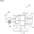
- FIG. 2 shows an internal configuration of terminal device 102 , which may include antenna system 202 , radio frequency (RF) transceiver 204 , baseband modem 206 (including digital signal processing subsystem 208 and controller 210 ), application processor 212 , memory 214 , and power supply 216.
- RF radio frequency
- terminal device 102 may include one or more additional hardware, software, and/or firmware components (such as processors/microprocessors, controllers/microcontrollers, other specialty or generic hardware/processors/circuits, etc.), peripheral device(s), memory, power supply, external device interface(s), subscriber identity module(s) (SIMs), user input/output devices (display(s), keypad(s), touchscreen(s), speaker(s), external button(s), camera(s), microphone(s), etc.), etc.
- processors/microprocessors such as processors/microprocessors, controllers/microcontrollers, other specialty or generic hardware/processors/circuits, etc.
- peripheral device(s) such as processors/microprocessors, controllers/microcontrollers, other specialty or generic hardware/processors/circuits, etc.
- peripheral device(s) such as processors/microprocessors, controllers/microcontrollers, other specialty or generic hardware/processors/circuits, etc.
- terminal device 102 may transmit and receive radio signals over one or more radio access networks.
- Baseband modem 206 may direct such communication functionality of terminal device 102 according to the communication protocols associated with each radio access network, and may execute control over antenna system 202 and RF transceiver 204 in order to transmit and receive radio signals according to the formatting and scheduling parameters defined by each communication protocol.
- various actual designs may include separate communication components for different supported radio access technologies (e.g., a separate antenna, RF transceiver, digital signal processing subsystem, and controller), for purposes of conciseness the configuration of terminal device 102 shown in FIG. 2 depicts only a single instance of each such components.
- terminal device 102 may include separate antennas, RF transceivers, digital signal processing subsystem, and and/or controllers for different supported radio access technologies, such as a set of first generation (1G) components, a set of second generation (2G) component, a set of third generation (3G) components, a set of fourth generation (4G) component, etc., and/or a set of components for a first short-range radio technology (e.g., WiFi), a set of component for a second short-range radio technology (e.g., Bluetooth), and so forth.
- a first short-range radio technology e.g., WiFi
- a second short-range radio technology e.g., Bluetooth
- Terminal device 102 may transmit and receive radio signals with antenna system 202 , which may include analog antenna combination and/or beamforming circuitry and may be a single antenna or an antenna array that includes multiple antennas and.
- antenna system 202 may include analog antenna combination and/or beamforming circuitry and may be a single antenna or an antenna array that includes multiple antennas and.
- RF transceiver 204 may receive analog radio frequency signals from antenna system 202 and perform analog and digital RF front-end processing on the analog radio frequency signals to produce digital baseband samples (e.g., In-Phase/Quadrature (IQ) samples) to provide to baseband modem 206.
- digital baseband samples e.g., In-Phase/Quadrature (IQ) samples
- RF transceiver 204 may accordingly include analog and digital reception components including amplifiers (e.g., a Low Noise Amplifier (LNA)), filters, RF demodulators (e.g., an RF IQ demodulator)), and analog-to-digital converters (ADCs) to convert the received radio frequency signals to digital baseband samples.
- LNA Low Noise Amplifier
- RF demodulators e.g., an RF IQ demodulator
- ADCs analog-to-digital converters
- TX transmit path
- RF transceiver 204 may receive digital baseband samples from baseband modem 206 and perform analog and digital RF front-end processing on the digital baseband samples to produce analog radio frequency signals to provide to antenna system 202 for wireless transmission.
- RF transceiver 204 may thus include analog and digital transmission components including amplifiers (e.g., a Power Amplifier (PA), filters, RF modulators (e.g., an RF IQ modulator), and digital-to-analog converters (DACs) to mix the digital baseband samples received from baseband modem 206 to produce the analog radio frequency signals for wireless transmission by antenna system 202.
- Baseband modem 206 may control the RF transmission and reception of RF transceiver 204 , which can include specifying the transmit and receive radio frequencies for operation of RF transceiver 204.
- radio transceiver 204 may be a software-defined radio (SDR) component implemented as a processor configured to execute software-defined instructions that specify radio frequency processing routines
- baseband modem 206 may include digital signal processing subsystem 208 , which may perform physical layer (PHY; Layer 1) transmission and reception processing to prepare outgoing transmit data provided by controller 210 for transmission via RF transceiver 204 and prepare incoming received data provided by RF transceiver 204 for processing by controller 210.
- Digital signal processing subsystem 210 may accordingly perform one or more of error detection, forward error correction encoding/decoding, channel coding and interleaving, physical channel modulation/demodulation, physical channel mapping, radio measurement and search, frequency and time synchronization, antenna diversity processing, power control and weighting, rate matching, retransmission processing, etc.
- Digital signal processing subsystem 208 may be structurally realized as hardware (e.g., as one or more digitally-configured hardware circuits, such as ASICs or FPGAs), as software (e.g., one or more processors configured to retrieve and execute program code that defines arithmetic, control, and/or I/O instructions and is stored in a non-transitory computer-readable storage medium), or as a mixed combination of hardware and software.
- digital signal processing subsystem 208 may include a controller configured to control the various hardware and software processing components of digital signal processing subsystem 208 in accordance with physical layer control logic defined by the communications protocol for the relevant radio access technologies.
- digital signal processing subsystem 208 may include one or more digitally-configured hardware circuits that are individually configured to perform a particular processing function. The controller may therefore distribute processing tasks to the one or more digitally configured hardware circuits, which may perform their assigned processing function on input data and provide the controller with the resulting output data.
- digital signal processing subsystem 208 is depicted as a single component in FIG. 2 , digital signal processing subsystem 208 may be collectively implemented as separate sections of physical layer processing components where each respective section is dedicated to, for example, the physical layer processing of a particular radio access technology.
- Terminal device 102 may be configured to operate according to one or more radio access technologies, which may be directed by controller 210.
- Controller 210 may thus be responsible for controlling the radio communication components of terminal device 102 (antenna system 202 , RF transceiver 204 , and digital signal processing subsystem 208 ) in accordance with the communication protocols of each supported radio access technology, and accordingly may represent the Access Stratum and Non-Access Stratum (NAS) (also encompassing Layer 2 and Layer 3) of each supported radio access technology.
- Controller 210 may be structurally embodied as a protocol processor configured to execute protocol software (retrieved from a controller memory) and subsequently control the radio communication components of terminal device 102 in order to transmit and receive communication signals in accordance with the corresponding protocol control logic defined in the protocol software.
- Controller 210 may therefore be configured to manage the radio communication functionality of terminal device 102 in order to communicate with the various radio access and core network components of radio communication network 100 , and accordingly may be configured according to the communication protocols for multiple radio access technologies.
- controller 210 may be a unified controller that is collectively responsible for all supported radio access technologies, while in other aspects controller 210 may include multiple separate controllers where each controller is a dedicated controller for a particular radio access technology or group of technologies, such as a dedicated controller for a first radio access technology and a dedicated controller for a second radio access technology.
- controller 210 may be responsible for directing radio communication activity of terminal device 102 according to the communication protocols of the supported radio access technologies.
- antenna system 202 and RF transceiver 204 may similarly be partitioned into multiple dedicated component sets that each respectively correspond to one or more of the supported radio access technologies.
- controller 210 may be configured to control the radio communication operations of terminal device 102 in accordance with, for example, a master/slave RAT hierarchical or multi-SIM scheme.
- Terminal device 102 may also include application processor 212 , memory 214 , and power supply 212.
- application processor 212 may be a CPU configured to execute various applications and/or programs of terminal device 102 at an application layer of terminal device 102 , such as an operating system (OS), a user interface (UI) for supporting user interaction with terminal device 102 , and/or various user application programs.
- the application processor may interface with baseband modem 206 as an application layer to transmit and receive user data such as voice data, audio/video/image data, messaging data, application data, basic Internet/web access data, etc., over the radio network connection(s) provided by baseband modem 206.
- Memory 214 may be a memory component of terminal device 102 , such as a hard drive or another such permanent memory device. Although not explicitly depicted in FIG. 2 , in some aspects the various other components of terminal device 102 shown in FIG. 2 may additionally each include integrated permanent and non-permanent memory components, such as for storing software program code, buffering data, holding current state information, etc.
- Power supply 216 may be an electrical power source that provides power to the various electrical components of terminal device 102. Depending on the design of terminal device 102 , power supply 216 may be a 'definite' power source such as a battery (rechargeable or disposable) or an 'indefinite' power source such as a wired electrical connection. Operation of the various components of terminal device 102 may thus pull electrical power from power supply 216.
- a 'definite' power source such as a battery (rechargeable or disposable) or an 'indefinite' power source such as a wired electrical connection. Operation of the various components of terminal device 102 may thus pull electrical power from power supply 216.
- Terminal devices 102 and 102 may execute mobility procedures to connect to, disconnect from, and switch between available network access nodes of the radio access network of radio communication network 100.
- terminal devices 102 and 102 may be configured to select and re-select between the available network access nodes in order to maintain a suitable radio access connection with the radio access network of radio communication network 100.
- terminal device 102 may establish a radio access connection with network access node 110 while terminal device 102 may establish a radio access connection with network access node 120.
- terminal devices 102 or 102 may seek a new radio access connection with another network access node of radio communication network 100.
- terminal device 102 may move from the coverage area 122 of network access node 120 into the coverage area 112 of network access node 110. As a result, the radio access connection with network access node 120 may degrade, which terminal device 102 may detect via radio measurements (e.g., signal strength or signal quality measurements) of network access node 120. Depending on the mobility procedures defined in the appropriate communication protocols for radio communication network 100 , terminal device 102 may seek a new radio access connection (which may be triggered at terminal device 102 or by the radio access network), such as by performing radio measurements on neighboring network access nodes to determine whether any neighboring network access nodes can provide a suitable radio access connection.
- a new radio access connection which may be triggered at terminal device 102 or by the radio access network
- terminal device 102 may identify network access node 110 (which may be selected by terminal device 102 or selected by the radio access network) and transfer to a new radio access connection with network access node 110.
- network access node 110 which may be selected by terminal device 102 or selected by the radio access network
- Such mobility procedures including radio measurements, cell selection/reselection, and handover are established in the various communication protocols and may be employed by terminal devices and the radio access network in order to maintain strong radio access connections between each terminal device and the radio access network across any number of different radio access network scenarios.
- terminal device 102 may receive a transmission
- the same may apply to the relevant components of terminal device 104 that may perform the described function, e.g., the receiver may receive the transmission.
- FIG. 3 shows an internal configuration of a network access node such as network access node 110.
- network access node 110 may include antenna system 302 , radio transceiver subsystem 304 , and communication subsystem 306 (including physical layer subsystem 308 and controller 310 ).
- network access node 110 may transmit and receive radio signals via antenna system 302 , which may be an antenna array including multiple antennas.
- Radio transceiver subsystem 304 may perform transmit and receive RF processing to convert outgoing digital data from communication subsystem 306 into analog RF signals to provide to antenna system 302 for radio transmission and to convert incoming analog RF signals received from antenna system 302 into digital data to provide to communication subsystem 306.
- Physical layer subsystem 308 may be configured to perform transmit and receive PHY processing on digital data received from radio transceiver subsystem 304 to provide to controller 110 and on digital data received from controller 310 to provide to radio transceiver subsystem 304.
- Controller 310 may control the communication functionality of network access node 110 according to the corresponding communication protocols, e.g., LTE, which may include exercising control over antenna system 302 , radio transceiver subsystem 304 , and physical layer subsystem 308.
- radio transceiver subsystem 304 may be structurally realized as hardware (e.g., as one or more digitally-configured hardware circuits, such as ASICs or FPGAs), as software (e.g., one or more processors configured to retrieve and execute program code that defines arithmetic, control, and/or I/O instructions and is stored in a non-transitory computer-readable storage medium), or as a mixed combination of hardware and software.
- radio transceiver subsystem 304 may be a radio transceiver including digital and analog radio frequency processing and amplification circuitry.
- radio transceiver subsystem 304 may be a software-defined radio (SDR) component implemented as a processor configured to execute software-defined instructions that specify radio frequency processing routines.
- physical layer subsystem 308 may include a controller and one or more hardware accelerators, wherein the controller is configured to control physical layer processing and offload certain processing tasks to the one or more hardware accelerators.
- controller 310 may be a controller configured to execute software-defined instructions that specify upper-layer control functions. In some aspects, controller 310 may be limited to radio communication protocol stack layer functions, while in other aspects controller 310 may also be responsible for transport, internet, and application layer functions.
- Network access node 110 may thus provide the functionality of network access nodes in radio communication networks by providing a radio access network to enable served terminal devices to access desired communication data.
- network access node 110 may also interface with a core network, one or more other network access nodes, or various other internet networks and servers via a wired or wireless backhaul interface.
- FIG. 4 shows an exemplary configuration in accordance with some aspects where network access node 110 interfaces with core network 402 , which may be a cellular core network.
- Core network 402 may provide a variety of functions essential to operation of radio communication network 100 , such as data routing, authenticating and managing users/subscribers, interfacing with external networks, and various network control tasks. Core network 402 may therefore provide an infrastructure to route data between terminal device 104 and various external networks such as data network 404 and data network 406.
- Terminal device 104 may thus rely on the radio access network provided by network access node 110 to wirelessly transmit and receive data with network access node 110, which may then provide the data to core network 402 for further routing to external locations such as data networks 404 and 406 (which may be packet data networks (PDNs)). Terminal device 104 may therefore establish a data connection with data network 404 and/or data network 406 that relies on network access node 110 and core network 402 for data transfer and routing.
- data networks 404 and 406 which may be packet data networks (PDNs)
- Radio communications between terminal devices and network access nodes may be executed according to standardized communication protocols that are specific to the utilized radio access technology. As previously described regarding the functionalities of baseband modem 206 of terminal device 102 and communication subsystem 306 of network access node 110 , these communication protocols may govern parameters such as signal formatting, transmission and reception scheduling, spectrum/bandwidth allocation, channel selection, mobility, connection management, and various higher-level control functionalities.
- Modulation and demodulation may be an important component of signal formatting protocols related to the physical (PHY) layer, where many radio communication protocols may utilize constellation-based modulation schemes such as Quadrature Amplitude Modulation (QAM).
- a transmitter may generate a stream of digital data (e.g., a sequence of '1's and '0s') to be transmitted to a counterpart receiver.
- the transmitter may then partition the stream of digital data into separate blocks, map each block of digital data to one of a plurality of predefined modulation symbols to obtain a modulation symbol, mix the modulation symbol onto an RF carrier, and then wirelessly transmit the resulting RF data to the receiver.
- the receiver may perform a demapping operation on the received modulation symbols to recover the original data bits for each modulation symbol, thus obtaining the original stream of digital data.
- the number of predefined modulation symbols of the modulation scheme is directly proportional to the supported data rate. For example, higher numbers of modulation symbols (i.e. a higher modulation order) in a given modulation scheme will enable higher numbers of bits to be transmitted with each modulation symbol.
- aspects described herein may utilize 3D modulation with beam-hopping in which additional data can be encoded by virtue of which out a of a predefined set of transmitters performs transmission of the data.
- additional data can be encoded into a transmission stream by selecting a particular transmitter from the predefined set that represents the additional data.
- a receiver can then recover the standard modulation symbol via demodulation and identify which transmitter of the predefined set transmitted the received data, and in doing so can recover the entirety of the transmitted data. This can therefore increase the data rate without increasing the modulation order of the standard modulation symbol, and can as a result avoid the increased susceptibility to noise of higher-order modulation schemes.
- FIG. 5 shows exemplary diagrams 501 and 502 illustrating 3D modulation with beam-hopping according to some aspects.
- a transmit bit vector may be used to select a modulation symbol according to, for example, a QAM-256 (quadrature amplitude modulation) constellation, where each modulation symbol may uniquely correspond to an 8-bit vector.
- the transmit bit vector is "10110011", which corresponds to a modulation symbol in a QAM-256 scheme.
- a transmitter may map the transmit bit vector "10110011" to the appropriate modulation symbol in the QAM-constellation, and may then transmit the modulation symbol as a wireless RF signal.
- diagram 501 shows mapping and transmission according to 3D modulation with beam-hopping.
- the transmit bit vector "10110011” can be divided into two component bit vectors.
- Component bit vector 503 equal to "10” corresponds to a transmitter index for a specific transmitter of a set of predefined transmitters, while component bit vector 504 is composed of the remaining bits "110011" of the transmit bit vector.
- the transmit bit vector of diagram 501 can be transmitted by a) selecting the transmitter out of the predefined set of transmitters that is assigned a transmit index equal to component bit vector 503 (e.g., "10") as the source transmitter, and b) mapping and transmitting the component bit vector 504 (e.g., 110011") with the selected source transmitter.
- component bit vector 503 e.g., "10"
- mapping and transmitting the component bit vector 504 e.g., 110011
- the data of component bit vector 503 will be encoded by virtue of which of the predefined set of transmitters is the source transmitter (i.e., which performs the transmission), while the data of component bit vector 504 can be encoded and transmitted as a standard modulation symbol.
- various 3D modulation with beam-hopping aspects may utilize a specific configuration to encode the transmitter index component vector, i.e. component bit vector 504.
- these aspects may utilize a predefined assignment of transmit indices to each of a predefined set of transmitters.
- the example described above with a length-2 transmitter index component vector may have a predefined set of at least four transmitters, where the possible two-bit transmit indices "00", "01", "10", and "11" may each be assigned to a respective one of the four transmitters.
- the transmitter index component vector composed of the first two bits can be identified, and the transmitter having a transmitter index that matches the transmitter index component vector can be selected as the source transmitter to transmit the modulation symbol component vector as a modulation symbol.
- the counterpart receiver can then demodulate the received modulation symbol via a demodulation operation to recover the modulation symbol component vector, and then identify which of the predefined set of transmitters was the source transmitter.
- the receiver can then determine the transmitter index component vector as the transmitter index of the source transmitter.
- each bit vector can result in a different transmitter (on account of differing transmitter index component vectors) and/or a different modulation symbol (on account of differing modulation symbol component vectors).
- the transmitter may therefore change, or 'hop', on a per-modulated symbol basis while at least some of the transmitted data is encoded on the basis of spatial differences between the potential transmitters, this can be referred to as 3D modulation with beam-hopping.
- FIG. 6 shows an exemplary diagram illustrating 3D modulation with beam-hopping according to some aspects.
- terminal device 102 may be located in proximity (e.g., within the coverage area and/or within range) of multiple network access noes 110 , 120 , 130 , and 140.
- network access nodes 110-140 may be macrocell network access nodes, and therefore may have a large coverage area in order of kilometers.
- network access nodes 110-140 may be microcell network access nodes, or 'small cells', and may have coverage areas in the order of tens or hundreds of meters.
- network access nodes 110-140 may include both macrocell and microcell network access nodes. While the example of FIG.
- the number of network access nodes is scalable to any number, where the number of bits in the transmitter index component vector will scale accordingly.
- the number of bits represented by the transmitter index component vector for M transmitters is given as 2 M , quantities of transmitters equal to a power of two may be advantageous in certain aspects.
- each of network access nodes 110-140 can thus be assigned a 2-bit transmitter index, where, for example, network access node 110 has transmitter index "00", network access node 120 has transmitter index "01", network access node 130 has transmitter index "10", and network access node 140 has transmitter index "11".
- This exemplary transmitter index scheme can be scaled to other values for the number of transmitters/size of the predefined set M and other lengths for the transmitter index component vector/transmitter index log 2 M .
- M may reduce the order of the modulation scheme used to transmit the modulation symbol component vector (and thus improve SNR); however, there may only be a limited number of transmitters available that can only satisfy certain values for M , such as where only a limited number of network access nodes are within range and/or where only a limited number of network access nodes can be effectively differentiated from each other to identify source transmitters.
- this component vector allocation scheme used to split the transmit bit vector into a transmitter index component vector and modulation symbol component vector is exemplary, and other component vector allocation schemes (e.g., that map bits at different positions of the transmit bit vector to the transmitter index component vector and modulation symbol component vector) can equivalently be used.
- Terminal device 102 may then receive and process the wireless RF signal from network access node 130 to recover the modulation symbol and the corresponding modulation symbol component vector "110011". In order to recover the entire transmit bit vector, terminal device 102 may then determine which of network access nodes 110-140 transmitted the modulation symbol (as any of the predefined set of transmitters can transmit any given data modulation symbol). For example, terminal device 102 may identify that network access node 130 transmitted the modulation symbol, and, as the transmitter indices for network access nodes 110-140 are also known at terminal device 102 , may determine that the transmitter index component vector is equal to transmitter index "10" of network access node 130.
- Terminal device 102 may thus have both the transmitter index component vector "10" (by virtue of identifying network access node 130 as the transmitter) and the modulated symbol component vector "110011” (by virtue of demodulating the modulation symbol), and may then combine the transmitter index component vector "10" and the modulated symbol component vector "110011” to recover the entire transmit bit vector "10110011".
- Network access nodes 110-140 may then alternate between transmitting modulation symbol component vectors for a sequence of transmit bit vectors dependent on the transmitter index component vector for each. As shown in FIG. 7 , controller 602 may receive another transmit bit vector 704 equal to "11101100". Using the exemplary component vector allocation scheme demonstrated above, controller 602 may split transmit bit vector 704 into the transmitter index component vector "11” and the modulation symbol component vector "101100". Controller 602 may then determine which of network access nodes 110-140 has a transmitter index equal to the transmitter index component vector "11" and identify network access node 140.
- Controller 602 may then provide the modulation symbol component vector "101100" to network access node 140 , which network access node 140 may process to obtain a modulation symbol and transmit the modulation symbol to terminal device 102 as a wireless RF signal.
- Terminal device 102 may receive the wireless RF signal and demodulate the modulation symbol to obtain the modulation symbol component vector "101100", and may then determine that network access node 140 transmitted the modulation symbol to obtain the transmitter index component vector "11”.
- Terminal device 102 may then recombine the transmitter index component vector "11” and the modulation symbol component vector "101100” to obtain the transmit bit vector "11101100".
- source transmitter (out of network access nodes 110-140 ) may switch, or 'hop', on a per-transmit bit vector basis depending on the transmitter index component vector of each transmit bit vector.
- this can reduce the modulation order without reducing the data rate and as a result improve SNR and reception performance.
- QAM-256 into QAM-64 this description is demonstrative and can be scaled to any suitable modulation order that scales according to the number of bits in the transmitter index component vector and the modulation symbol component vector.
- a single stream case i.e.
- these aspects can also be applied to multicarrier schemes where a different symbol is transmitted on each of a plurality of subcarriers during each symbol period. Accordingly, during a given symbol period, the symbol on each subcarrier is transmitted according to the transmitter index component vector of the corresponding transmit bit vector.
- terminal device 102 may demodulate a received modulation symbol to determine the modulation symbol component vector and identify which of network access nodes 110-140 transmitted the modulation symbol to determine the transmitter index component vector. However, determining which of the predefined set of transmitters was the source transmitter for each received modulation symbol may in some cases be a relatively complex procedure.
- terminal device 102 may utilize special processing techniques to lower the complexity of this receive operation.
- terminal device 102 may utilize a spectrum envelope-based comparison in order to narrow down the possibilities for which of the predefined set of transmitters is the source transmitter.
- Terminal device 102 may then demodulate the received modulation symbol using a resulting set of source transmitter candidates (as opposed to the full predefined set of transmitters), and, due to the smaller number of possible source transmitters, may reduce the processing complexity of the demodulation operation.
- any one of network access nodes 110-140 could be the source transmitter for a given received modulation symbol.
- terminal device 102 may perform preliminary processing to eliminate one or more of network access nodes 110-140 (the predefined set of transmitters) from contention as the source transmitter, and can thus obtain a set of source transmitter candidates.
- Terminal device 102 can then demodulate the received modulation symbol while considering only the set of source transmitter candidates as candidates for the source transmitter. As terminal device 102 considers fewer transmitters as the source transmitter, terminal device 102 can reduce the complexity of the demodulation operation.
- the demodulation operation for recovering both the transmitter index component vector and the modulation symbol component vector from a received modulation symbol can be a complex process.
- terminal device 102 can utilize a maximum likelihood (ML) detector to demodulate a received modulation symbol.
- ML detection for single transmitter cases (e.g., where a fixed serving network access node transmits each modulation symbol)
- a demodulator of terminal device 102 can, for a received modulation symbol, test each possible modulation symbol (e.g., 64 total for QAM-64, 256 total for QAM-256, etc.) to determine which out of all of the possible modulation symbols presents the 'maximum likelihood' of being the transmitted modulation symbol.
- the demodulator can test each of the 64 QAM symbols to determine which has the highest likelihood of being the transmitted modulation symbol corresponding to the received modulation symbol.
- the demodulator can generally use an estimate of the channel, known as an 'effective channel' to compensate for such channel effects during demodulation. Even though some noise effects, in addition to any leftover residue from errors in the channel estimation, will remain in the channel-corrected modulation symbol, the demodulator can generally still determine which of the possible modulation symbols was 'most likely' the transmitted modulation symbol when using ML detection.
- the effective channel used by an ML detector is the effective channel for the single, fixed transmitter, which remains constant over a series of received modulation symbols.
- This use of effective channels in ML detection is therefore complicated in the 3D modulation with beam hopping case, as any one of the predefined set of transmitters could have transmitted the modulation symbol, thus also meaning that the effective channel for the received modulation symbol could have been the effective channel for any of the predefined set of transmitters.
- the ML detector instead of trying out, for example, 64 possible modulation symbols with a single effective channel for demodulation for QAM-64, the ML detector will try out 64 possible modulation symbols for each of the M possible effective channels. This results in a significant complexity increase, where the demodulator will check 2 N M candidates total (for the 2 N possible modulation symbols and M possible transmitters).
- aspects of this disclosure can reduce the demodulation complexity by narrowing down the predefined set of transmitters to a set of source transmitter candidates that are considered as candidates for the source transmitter during ML detection. For example, if terminal device 102 can reduce the predefined set of M transmitters to a reduced set of L transmitters (where L ⁇ M ), terminal device 102 can reduce the complexity of the demodulation operation, as the ML detector will only test L effective channels instead of M effective channels. This can speed up demodulation and/or reduce the amount of processing resources used for demodulation.
- various aspects of this disclosure may use a filtering scheme based on spectrum envelope comparison to narrow down the possible source transmitters into a set of source transmitter candidates, i.e., to reduce the predefined set of M transmitters to a reduced set of L transmitters that are considered as candidates for the source transmitter for a given received modulation symbol. These aspects can then perform ML detection on the set of source transmitter candidates to recover the original transmit bit vector.
- FIG. 8 shows an exemplary internal configuration of terminal device 102 related to demodulation according to some aspects of 3D modulation with beam-hopping. As the illustrated depiction of FIG. 8 is focused on demodulation, for purposes of conciseness FIG. 8 may not expressly show certain other components of terminal device 102. As shown in FIG. 8 , in some aspects baseband modem 206 of terminal device 102 may include ML detector 802, channel estimator (CE) 804 , spectrum analyzer 806 , selector 808 , and demapper 810 .
- CE channel estimator
- Each of ML detector 802 , channel estimator (CE) 804 , spectrum analyzer 806 , selector 808 , and demapper 810 may be structurally realized as hardware (e.g., as one or more digitally-configured hardware circuits, such as ASICs, FPGAs, or another type of dedicated hardware circuit), as software (e.g., one or more processors configured to retrieve and execute program code that defines arithmetic, control, and/or I/O instructions and is stored in a non-transitory computer-readable storage medium), or as a mixed combination of hardware and software. While ML detector 802 , channel estimator 804 , spectrum analyzer 806 , selector 808 , and demapper 810 are shown separately in FIG.
- ML detector 802 , channel estimator 804 , spectrum analyzer 806 , selector 808 , and demapper 810 can therefore each be implemented as separate hardware and/or software components, or one or more of ML detector 802 , channel estimator 804 , spectrum analyzer 806 , selector 808 , and demapper 810 can be combined into a unified hardware and/or software component (for example, a hardware-defined circuitry arrangement including circuitry to perform multiple functions, or a processor configured to execute program code that defines instructions for multiple functions).
- a hardware-defined circuitry arrangement including circuitry to perform multiple functions, or a processor configured to execute program code that defines instructions for multiple functions.
- terminal device 102 may be configured to utilize a spectrum envelope-based analysis to pre-process modulation symbols to identify a set of source transmitter candidates for consideration as source transmitter candidates to perform ML demodulation.
- terminal device 102 may derive a spectrum envelope for each of the predefined set of transmitters from a first set of resource units, and may then derive spectrum envelopes from a second set of resource units.
- Terminal device 102 may then compare each spectrum envelope from the second set of resource units to the spectrum envelopes for the predefined set of transmitters to see if there are any matching spectrum envelopes.
- Terminal device 102 may then, for each resource unit in the second set of resource units, narrow down the source transmitter candidates and accordingly narrow down the effective channels that are tested during ML detection.
- FIG. 9 shows exemplary method 900 , which terminal device 102 may execute using the internal configuration shown in FIG. 8 .
- channel estimator 804 may first in stage 902 perform channel estimation using reference signals to estimate the effective channels of the predefined set of transmitters, namely network access nodes 110-140.
- Terminal device 102 may already have prearranged knowledge of the identities and the transmitter indices of the network access nodes that are currently assigned to the predefined set of transmitters.
- terminal device 102 may be configured to receive control signaling from radio communication network 100 that identifies the predefined set of transmitters (e.g., network access nodes 110-140 ) and specifies the transmitter indices (e.g., "00", "01", “10", and "11", respectively) of the predefined set of transmitters.
- the control signaling may also specify the total size of the transmit bit vectors, the size of the modulation component vector, and the size of the transmitter index component vector.
- FIG. 10 shows an exemplary resource grid 1000 that illustrates a time-frequency plot of reference symbols and modulation symbols.
- certain resource units time-frequency resources; for example, Resource Elements (REs) in LTE
- REs Resource Elements
- Each resource unit may be uniquely identified by a symbol period (containing one modulation symbol) and a subcarrier.
- cells may be configured to transmit cell-specific reference signals (CRS) at specific REs according to their physical cell identity (PCI), where each PCI specifies a unique set of REs that the cell is expected to transmit a CRS on.
- PCI physical cell identity
- each of network access nodes 110-140 may be configured to transmit reference signals at specific resource units according to their identities, where each resource unit assigned to a reference signal therefore holds a reference symbol transmitted by the corresponding network access node.
- each of the reference symbols shown in resource grid 1000 may be a reference symbol transmitted by one of network access nodes 110-140 (the predefined set of transmitters), where channel estimator 804 is aware of which specific resource units contain reference symbols transmitted by each of network access nodes 110-140 by virtue of their identities (e.g., PCI or some other transmitter identifier).
- Channel estimator 804 may therefore estimate the effective channel for each of network access nodes 110-140 in stage 902 based on the reference symbols received from each of network access nodes 110-140. In some aspects, this may include comparing a received reference symbol with a counterpart predefined reference symbol to characterize the effects of the channel on the transmitted reference symbol during propagation. In some aspects, as the reference symbols are located at different resource units, this can also include interpolating over time and/or frequency to estimate the effective channels at the resource units that do not contain reference symbols.
- Channel estimator 804 may therefore estimate the effective channel for each of network access nodes 110-140 , and may provide the effective channel estimates to ML detector 802. ML detector 802 may then perform ML detection on a set of received resource units S set (each on a different subcarrier in the same symbol period) to obtain the transmitted modulation symbols (giving the modulation component vector) and the transmitter indices (giving the transmitter index component vector) for each resource unit in S set in stage 904.
- Each likelihood metric uniquely corresponds to the particular modulation symbol and effective channel which ML detector 802 used to calculate the likelihood metric.
- ML detector 802 may then select the modulation symbol-effective channel pair that produces the highest likelihood metric, and may then take the modulation symbol as the modulation symbol component vector and the transmitter index corresponding to the effective channel as the transmitter index component vector.
- ML detector 802 may, for each resource unit in S set , obtain the transmitter index and the transmitted modulation symbol in stage 904. ML detector 802 may then check that the set of resource units S set contains at least one resource unit transmitted from each of the predefined set of transmitters in stage 906. If S set does not contain at least one resource unit transmitted by each of network access nodes 110-140 , ML detector 802 may continue to perform ML detection on other resource units (on different subcarriers in the same symbol period as the original resource units of S set ) until ML detector 802 has identified at least one resource unit transmitted by each of network access nodes 110-140 , where the final version of S set is a size- M set containing exactly one resource unit from each of the predefined set of M transmitters. In other words each transmitter index may be represented exactly once by the resource units S set .
- ML detector 802 may then specify the resource units S set (e.g., according to subcarrier index) and the transmitter indices (as identified according to the effective channel) to spectrum analyzer 806.
- Spectrum analyzer 806 may then in stage 908 calculate the spectrum envelopes P ⁇ set of the resource units S set .
- the spectrum envelopes P ⁇ set are 'known spectrum envelopes'.
- S set contains one resource unit transmitted by each of the predefined set of transmitters
- the known spectrum envelopes P ⁇ set include a spectrum envelope of a resource unit transmitted by each of the predefined set of transmitters.
- the known spectrum envelopes P ⁇ set calculated by spectrum analyzer 806 may therefore each characterize a respective one of the predefined set of transmitters.
- Terminal device 102 may then use the known spectrum envelopes as a means to differentiate between the predefined set of transmitters, such as to determine which of the predefined set of transmitters is likely to be the source transmitter for a given received modulation symbol.
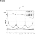
- spectrum envelope 1102 is the spectrum envelope of P ⁇ set calculated by spectrum analyzer 806 from the resource unit of S set transmitted by network access node 110
- spectrum envelope 1104 is the spectrum envelope of P ⁇ set calculated by spectrum analyzer 806 from the resource unit of S set transmitted by network access node 120
- spectrum envelope 1106 is the spectrum envelope of P ⁇ set calculated by spectrum analyzer 806 from the resource unit of S set transmitted by network access node 130
- spectrum envelope 1108 is the spectrum envelope of P ⁇ set calculated by spectrum analyzer 806 from the resource unit of S set transmitted by network access node 140.
- each of spectrum envelopes 1102-1108 may have a unique spectrum envelope, which can form a basis for differentiation between which of the predefined set of transmitters was the source transmitter for the corresponding resource units.
- spectrum analyzer 806 may utilize a particular algorithm to calculate the known spectrum envelopes P ⁇ set in stage 908 , such as any processing algorithm that calculates a spectrum envelope of a received signal.
- spectrum analyzer 806 may utilize a MUltiple SIgnal Classification (MUSIC) algorithm, or any similar algorithm that calculates a spectrum envelope or spectrum envelope, to process sampled data for each resource unit in S set to obtain the resulting known spectrum envelopes P ⁇ set .
- MUSIC MUltiple SIgnal Classification
- Other algorithms that can also be used in various aspects include the Estimation of Signal Parameters via Rotation Invariance Techniques (ESPIRIT), Maximum Likelihood, and Matrix Pencil algorithms.
- Such algorithms may take a digital sequence (e.g., a vector of baseband data) as input and produce a digital sequence as output.
- known spectrum envelopes P ⁇ set may each be a vector, such as vector of discretized angle points that give a power level at each angle (where, for example, spectrum envelopes 1102-1108 are each the plotted points of such a vector).
- spectrum envelopes obtained by spectrum analyzer 806 may be used; however, any type of spectrum envelope represented by a vector or set of power values over frequency can be used in the same manner.
- spectrum analyzer 806 may then in stage 910 calculate unknown spectrum envelopes P ⁇ non - set for the resource units S non - set , which are the remaining resource units that are not in S set .
- Spectrum analyzer 806 may calculate unknown spectrum envelopes P ⁇ non - set using the same algorithm as used in stage 908 to calculate the known spectrum envelopes P ⁇ set .
- Spectrum analyzer 806 may then provide the known spectrum envelopes P ⁇ set and the unknown spectrum envelopes P ⁇ set to selector 808.
- Selector 808 may then be configured in stage 912 to compare the known spectrum envelopes P ⁇ set to the unknown spectrum envelopes P ⁇ non - set to identify which known spectrum envelopes P ⁇ set match with each unknown spectrum envelope P ⁇ non - set .
- each of known spectrum envelopes P ⁇ set characterizes a respective one of network access nodes 110-140.
- a given known spectrum envelope of P ⁇ set matches an unknown spectrum envelope of P ⁇ non - set
- this may indicate that the resource unit of S set corresponding to the unknown spectrum envelope of P ⁇ non - set was transmitted by the transmitter characterized by known spectrum envelope of P ⁇ set , or in other words, that the resource unit of S set with which the known spectrum envelope of P ⁇ set was calculated has the same source transmitter as the resource unit of S non - set with which the unknown spectrum envelope of P ⁇ non - set was calculated.
- Selector 808 may be then configured to identify L matching spectrum envelopes from known spectrum envelopes P ⁇ set that match each unknown spectrum envelope P ⁇ non - set in stage 914 (where 1 ⁇ L ⁇ M ), and then to identify the transmitter indices for the matching spectrum envelopes (which are already known by virtue of the ML detection on S set from stage 904). These L transmitter indices of the matching spectrum envelopes therefore give the transmitter indices of the set of source transmitter candidates. Selector 808 may therefore identify transmitter indices for the L source transmitter candidates for each resource unit in S non - set .
- a distance metric such as a mean-squared or Euclidean distance.
- Selector 808 may then identify the L values of m ⁇ ⁇ 1, ..., M ⁇ for which ⁇ p set,m - p non-set ⁇ 2 is smallest in stage 914 , and may thus identify the L matching known spectrum envelopes and consequently the transmitter indices for the L source transmitter candidates.
- L may be fixed for each unknown spectrum envelope of P ⁇ non - set , or in other words, selector 808 may identify the same number L of source transmitter candidates for each resource unit of S non - set .
- L may vary for different resource units of S non - set , such as where selector 808 identifies L values of m for which ⁇ p set,m - p non-set, 1 ⁇ 2 is less than a predefined threshold (or in other words, for which the distance between p set,m and p non-set, 1 is less than some predefined amount).
- selector 808 may identify L transmitter indices (the transmitter indices for the set of source transmitter candidates) for each resource unit of S non - set that identify the transmitters of the predefined set of transmitters (e.g., network access nodes 110-140 ) that are candidates for being the source transmitter of each resource unit of S non - set .
- Selector 808 may then provide the L transmitter indices, for each resource unit of S non - set , to ML detector 802.
- ML detector 802 may then perform ML detection for the resource units in S non - set using the respective L transmitter indices for each resource unit of S non - set (the set of source transmitter candidates) in stage 916.
- ML detector 802 may therefore test, for each resource unit of S non - set , each of the possible modulation symbols using each of the L effective channels of the set of source transmitter candidates to determine which modulation symbol-effective channel pair presents the maximum likelihood of being the transmitted modulation symbol and source transmitter.
- L ⁇ M for at least some of the resource units of S non - set , depending on whether L is the same for all resource units of S non - set and whether L can equal M for some resource units of S non-set )
- the number of computations done by ML detector 802 is therefore fewer than the general case where all M effective channels are used during ML detection.
- FIG. 12 shows an exemplary illustration of the process of stages 912-916.
- Selector 808 may then select the L matching known spectrum envelopes of P ⁇ set that result in a minimum distance, and indicate which of the predefined set of transmitters correspond to the L matching known spectrum envelopes P ⁇ match to ML detector 802 (i.e., indicate the set of source transmitter candidates).
- ML detector 802 may then retrieve the L effective channels corresponding to the set of source transmitter candidates (provided by channel estimator 804 ) and perform ML detection using the L effective channels to identify which modulation symbol-effective channel pair is most likely to give the transmitted modulation symbol (e.g., identified by a unique modulation symbol index) and source transmitter (e.g., out of network access nodes 110-140 ) for the resource unit of S non - set currently being evaluated.
- Selector 808 and ML detector 802 may perform this process for each resource unit of S non - set to obtain a transmitter index and modulation symbol index for each received resource unit (e.g., all of the resource units of S set and S non - set , where ML detector 802 previously obtained the transmitter indices and modulation symbol indices for the resource units of S set in stage 904 ).
- ML detector 802 may then provide the transmitter index and modulation symbol index for each received resource unit to demapper 810 , which may then de-map the modulation symbols according to the modulation symbol indices to obtain the corresponding bits that give the modulation symbol component vector for each transmit bit vector.
- Demapper 810 may then combine the modulation symbol component vector with the transmitter index bit vector according on the transmitter index, and may therefore obtain the transmit bit vector for each resource unit (of S set and S non - set , which all occur in the same symbol period).
- ML detector 802 may therefore only perform ML detection (including testing all of the 2 N possible modulation symbols) for the lone effective channel indicated by selector 808.
- terminal device 102 may repeat the process of method 900 for each symbol period (as each resource unit is eligible to be transmitted by any of the predefined set of transmitters). Instead of performing ML detection on each resource unit according to the full set of M effective channels, terminal device 102 may instead narrow down the set of effective channels to L total and then perform ML detection using the L effective channels (for the set of source transmitter candidates).
- the use of spectrum envelopes detailed above may therefore provide a unique characteristic by which terminal device 102 can differentiate between the predefined set of transmitters and, for each resource unit, identify a reduced set of L transmitters as source transmitter candidates. This can therefore enable terminal device 102 to reduce the demodulation complexity for receiving data in a 3D modulation with beam-hopping scheme.
- the predefined set of transmitters may be dynamic, and can thus change over time.
- Radio communication network 100 may indicate these changes as control signaling transmitted to terminal device 102 , including changes in the transmitter indices (e.g., both for individual transmitters and for changes in the number of bits in the modulation symbol component vector and the transmitter index component vector) and in the transmitters assigned to the predefined set of transmitters.
- Terminal device 102 may then perform the same process of method 900 while taking into account any such changes.
- terminal device 102 may additionally or alternatively utilize another criteria to narrow down the predefined set of transmitters to obtain the reduced set of source transmitter candidates.
- spectrum analyzer 806 and selector 808 may utilize multipath profile to identify the reduced set of source transmitter candidates.
- the channels between terminal device 102 and each of the predefined set of transmitters e.g., network access nodes 110-140
- the delay and gain of each multipath element characterize the multipath profile, or the multipath impulse response, of the channel.
- each multipath profile is assumed to be different, and can thus be used a basis for differentiating between source transmitters.
- spectrum analyzer 806 may be configured to calculate the multipath profile for one or more of the resource unites in S non- s et , and selector 808 may compare the multipath profiles to the known multipath profile for each of the predefined set of transmitters. Selector 808 may then select the reduced set of source transmitter candidates for each resource unit based on whether any of the known multipath profiles match the multipath profile for the resource unit, and then indicate the reduced set of source transmitter candidates to ML detector 802 for ML detection.
- spectrum analyzer 806 and selector 808 may utilize multipath profiles in this manner in addition to spectrum envelope, such as an additional criteria with which to measure how likely it is that a given one of the predefined set of transmitters is the source transmitter.
- spectrum analyzer 806 and selector 808 may utilize multipath profiles instead of spectrum envelope, and may therefore identify the reduced set of source transmitter candidates for one or more resource units exclusively using multipath profiles.
- the aspects described herein may able to accurately narrow down the predefined set of transmitters to a set of source transmitter candidates in both Line-of-Sight (LOS) cases, i.e., where there is a direct path between the transmitters (e.g., network access node 110 ) and receiver (terminal device 102 ), and in non-LOS cases, i.e., where there is not a direct path between the transmitters and receiver.
- LOS Line-of-Sight
- non-LOS cases there may not be multipath components between the source transmitter and the terminal device 102. Accordingly, in such cases it may be possible to utilize an Angle-of-Arrival (AoA)-based technique to identify the source transmitter from the predefined set of transmitters.
- AoA Angle-of-Arrival
- terminal device 102 may determine the AoA of signals received from each of the predefined set of transmitters, and can thus identify the relative directions from terminal device 102 that each of the predefined set of transmitters are located. Terminal device 102 can then determine which of the predefined transmitters is the source transmitter for each received resource unit by calculating the AoA of each received resource unit and comparing these AoAs to the AoAs previously calculated for each of the predefined set of transmitters.
- AoA estimation may only be reliable when there is an LOS path between the transmitters and terminal device 102 , and accordingly AoA estimation may not be accurate for non-LOS cases.
- the MUSIC algorithm referenced above for calculation of the spectrum envelopes by spectrum analyzer 806 is one such algorithm that can be used for AoA estimation, where peaks in a given spectrum envelope vector can indicate the AoA of a given signal.
- each of network access nodes 110-140 may have an LOS path with terminal device 102
- spectrum envelopes 1302-1308 may be calculated according to a pseudospectra analysis algorithm such as MUSIC (thus yielding pseudospectrum envelopes).
- spectrum envelopes 1302-1308 may have very distinct peaks, where each peak occurs at a particular AoA degree as denoted on the X-axis. Accordingly, the AoA for each of network access nodes 110-140 can be identified from analysis of spectrum envelopes 1302-1308 , where, for example, the AoA for network access node 110 is around 120 digress, the AoA for network access node 120 is around 0 degrees, the AoA for network access node 130 is around 60 degrees, and the AOA for network access node 140 is around 180 degrees.
- spectrum envelopes 1102-1108 may be calculated when network access nodes 110-140 have non-LOS paths with terminal device 102. Accordingly, spectrum envelopes 1102-1108 may not have well-defined peaks at any particular angle, and may instead have slopes that are more shallow and gradual. Accordingly, terminal device 102 may not be able to identify the AoA as accurately for network access nodes 110-140 in the non-LOS cases, and consequently may not be able to utilize AoA during demodulation to identify the source transmitter.
- terminal device 102 may not be able to accurately determine the AoA in the non-LOS case, terminal device 102 can still utilize the spectrum envelope-based analysis described herein to differentiate between the predefined set of transmitters when identifying source transmitters.
- both the non-LOS spectrum envelopes 1102-1108 in chart 1100 and the non-LOS spectrum envelopes 1302-1308 in chart 1300 have a distinct spectrum envelope. Accordingly, even though the non-LOS spectrum envelopes 1302-1308 may not exhibit a definite AoA, terminal device 102 can still utilize the spectrum envelope of non-LOS spectrum envelopes 1302-1308 to differentiate between source transmitters according to the techniques described above regarding FIGs. 8 and 9 .
- terminal device 102 may utilize the spectrum envelope-based analysis techniques described herein for both LOS and non-LOS cases.
- the distance metric ⁇ p set,m - p non - set ⁇ 2 used to compare known spectrum envelopes of P ⁇ set and unknown spectrum envelopes P ⁇ non - set may be an effective mechanism for comparing spectrum envelopes regardless of whether the spectrum envelopes are LOS or non-LOS (although in some cases the distance metric-based comparison of spectrum envelopes may be more accurate for LOS spectrum envelopes due to their more definite envelopes).
- LOS channels may cause problems when attempting to differentiate between transmitters that have AoAs separated by 180 degrees.
- FIG. 14 shows an example in which a receiver using a uniform linear array may not be able to differentiate between transmitters 1402 and 1404 with AoAs separated by 180 degrees (namely, 170 degrees and 190 degrees).
- certain spectrum envelope calculation algorithms including the MUSIC algorithm, may calculate the same spectrum envelope for two different transmitters that have AoAs separated by 180 degrees when using a linear antenna array.
- antenna system 202 may be configured in configuration other than a uniform linear antenna array, such as in a circular antenna array.
- spectrum analyzer 806 may calculate different spectrum envelopes even for two transmitters positioned at AoAs separated by 180 degrees, which can therefore enable selector 808 to differentiate between the two transmitters. Additionally or alternatively, terminal device 102 may solve this problem by selecting the transmitters that are placed on AoAs between 0 to 180 degrees.
- terminal device 102 may be configured to dynamically switch between ML detection using a reduced set of source transmitter candidates, or 'reduced candidate ML detection, and ML detection using the full predefined set of transmitters, or 'full ML detection'.
- reduced candidate ML detection described above may reduce demodulation complexity, there may be a potential for some performance degradation. For instance, if selector 808 mistakenly omits the actual source transmitter for a given resource unit of S non - set from the reduced set of source transmitter candidates, ML detector 802 will not use the correct effective channel when performing ML detection. As a result, ML detector 802 will not determine the correct transmitter index (as the actual source transmitter will not be considered during ML detection), and may also experience demodulation error as the correct effective channel will not be used for channel equalization during ML detection.
- terminal device 102 may also include demodulation controller 1502.
- Demodulation controller 1502 may be a software (e.g., one or more processors configured to retrieve and execute program code) and/or a hardware (e.g., one or more digitally-configured hardware circuits) component, and may receive baseband data from RF transceiver 204 as input.
- Demodulation controller 1502 may then be configured to process the baseband data to determine, based on current conditions, whether to use reduced candidate ML detection or full ML detection.
- Demodulation controller 1502 may then provide ML detector 802 with a control signal that instructs ML detector 802 to use reduced candidate ML detection or full ML detection.
- ML detector 802 may perform ML detection, for each resource unit in S non - set , using the reduced set of source transmitter candidates (e.g., only with the effective channels for the L source transmitter candidates). Conversely, if demodulation controller 1502 instructs ML detector 802 to use full ML detection, ML detector 802 may perform ML detection, for each resource unit in S non - set , using the predefined set of transmitters (e.g., with the effective channels for all M of the predefined set of transmitters).
- demodulation controller 1502 may determine whether to use reduced candidate ML detection or full ML detection based on one or more communication condition indicators that indicate a characteristic of the current communication conditions of terminal device 102.
- exemplary communication condition indicators that demodulation controller 1502 can use can include one or more of modulation order, LOS/non-LOS channels, frequency band, and SNR.
- Demodulation controller 1502 may thus be configured to consider one or more of such communication condition indicators, and in some aspects may aim to balance between performance and demodulation complexity when deciding whether to use full or reduced candidate ML detection.
- the spectrum envelope-based reduced candidate ML detection described herein may be more accurate for high modulation orders than at lower modulation orders. Accordingly, if demodulation controller 1502 determines that the current modulation order (e.g., as specified to terminal device 102 as control signaling from radio communication network 100 ) is high, demodulation controller 1502 may be configured to instruct ML detector 802 to utilize reduced candidate ML detection (and vice versa for low modulation order).
- the current modulation order e.g., as specified to terminal device 102 as control signaling from radio communication network 100
- demodulation controller 1502 may be configured to instruct ML detector 802 to utilize reduced candidate ML detection (and vice versa for low modulation order).
- the spectrum envelope-based reduced candidate ML detection described herein may be accurate for LOS channels even when the modulation order is low, or if there is at least one strong non-LOS channel that can be clearly identified. Accordingly, if terminal device 102 has at least one strong LOS or non-LOS channel with the predefined set of transmitters (and, optionally, even when the modulation order is low), demodulation controller 1502 may be configured to instruct ML detector 802 to utilize reduced candidate ML detection (and vice versa for non-LOS channels). In some aspects, spectrum analyzer 806 may be configured to determine whether the channels are LOS channels or non-LOS channels, such as by evaluating the spectrum envelopes to determine whether there are definite peaks and/or steep slopes to positively identify an LOS channel.
- the spectrum envelope-based reduced candidate ML detection described herein may be more accurate at lower frequency bands since higher frequency bands have produce non-LOS channel characteristics (due to the increased propagation attenuation of higher frequencies). Accordingly, if terminal device 102 is receiving with a lower frequency band (and, optionally, even if using a low modulation order), demodulation controller 1502 may be configured to instruct ML detector 802 to utilize reduced candidate ML detection (and vice versa for higher frequency bands). In some aspects, demodulation controller 1502 may be configured to receive an indication of the frequency band currently being used from another component of terminal device 102 , such as a baseband controller or protocol processor responsible for managing transmission and/or reception channels.
- the spectrum envelope-based reduced candidate ML detection described herein may be more accurate at higher SNRs than for lower SNRs, in particular for non-LOS channels. Accordingly, if terminal device 102 has a low SNR (and, optionally, has non-LOS channels), demodulation controller 1502 may be configured to instruct ML detector 802 to utilize full ML detection (and vice versa for higher SNRs). In some aspects, demodulation controller 1502 may be configured to calculate the current SNR based on baseband data and/or may receive an indication of the current SNR from another SNR measurement component of terminal device 102.
- demodulation controller 1502 may be configured to decide whether to use reduced candidate ML detection or full ML detection, and to instruct ML detector 802 to perform demodulation accordingly. By switching between reduced candidate ML detection or full ML detection based on the current conditions, terminal device 102 may balance between performance and demodulation complexity.
- the proposed method is applicable to any set of wireless transmission sources which need to be differentiated by the receiver and which are characterized by i) different angles of arrival and ii) different multipath profiles.
- the method can be used by a base station / access point to differentiate between various UEs which are located on different geographic spots in proximity to the concerned base station / access point.
- This method may thus be useful, in some but not necessarily all cases, to improve decoding efficiency in general by first selecting a 'candidate subset' of all devices/base stations/access points/etc. which are then further considered by decoding their respective IDs in signaling fields, etc.
- FIG. 16 shows method 1600 of processing and demodulating wireless signals.
- method 1600 includes performing demodulation on a plurality of received modulation symbols to identify a plurality of source transmitters for the plurality of received modulation symbols ( 1602 ), comparing spectrum envelopes of the plurality of received modulation symbols with a spectrum envelope of a target received modulation symbol to select one or more of the plurality of source transmitters ( 1604 ), and performing demodulation on the target received modulation symbol based on the selected one or more of the plurality of source transmitters to identify a source transmitter for the target received modulation symbol ( 1606 ).
- FIG. 17 shows method 1700 of processing and demodulating wireless signals.
- method 1700 includes demodulating a plurality of received modulation symbols to identify, out of a plurality of transmitters, a source transmitter for each of the plurality of received modulation symbols ( 1702 ), comparing spectrum envelopes of the plurality of received modulation symbols with a spectrum envelope of a target received modulation symbol to select one or more source transmitter candidates out of the plurality of transmitters ( 1704 ), and demodulating the target received modulation symbol using channel estimates for the one or more source transmitter candidates to identify a source transmitter for the target received modulation symbol ( 1706 ).
- a device corresponding to a method detailed herein may include one or more components configured to perform each aspect of the related method.
Landscapes
- Engineering & Computer Science (AREA)
- Computer Networks & Wireless Communication (AREA)
- Signal Processing (AREA)
- Mobile Radio Communication Systems (AREA)
Claims (15)
- Kommunikationsvorrichtung (102), die für drahtlose Kommunikationen konfiguriert ist, wobei die Kommunikationsvorrichtung umfasst:einen Detektor (802), der so konfiguriert ist, dass er Demodulation an einer Mehrzahl von empfangenen Modulationssymbolen durchführt, um eine Mehrzahl von Ursprungssendern (110-140) für die Mehrzahl von empfangenen Modulationssymbolen zu identifizieren, wobei die identifizierte Mehrzahl von Ursprungssendern (110-140) jeden eines vordefinierten Satzes von Sendern umfasst; undeinen Selektor (808), der so konfiguriert ist, dass er Spektralhüllkurven der Mehrzahl von empfangenen Modulationssignalen mit einer Spektralhüllkurve eines empfangenen Zielmodulationssymbols vergleicht, um einen oder mehrere der Mehrzahl von Ursprungssendern auszuwählen, wobei der eine oder die mehreren der Mehrzahl von Ursprungssendern (110-140) ein reduzierter Teilsatz der Mehrzahl von Ursprungssendern (110-140) sind, wobei das empfangene Zielmodulationssymbol nicht zu der Mehrzahl von empfangenen Modulationssymbolen gehört, und wobei das empfangene Zielmodulationssymbol und die empfangenen Modulationssymbole in der gleichen Symbolperiode sind,wobei der Detektor (802) ferner so konfiguriert ist, dass er Demodulation am empfangenen Zielmodulationssymbol basierend auf dem einen oder den mehreren ausgewählten der Mehrzahl von Ursprungssendern (110-140) durchführt, um einen Ursprungssender für das empfangene Zielmodulationssymbol aus dem reduzierten Teilsatz zu identifizieren.
- Kommunikationsvorrichtung (102) nach Anspruch 1, wobei der Detektor (802) ferner zum Identifizieren eines gesendeten Modulationssymbols für das empfangene Zielmodulationssymbol durch Demodulation konfiguriert ist.
- Kommunikationsvorrichtung (102) nach Anspruch 2, ferner umfassend einen Demapper (810), der zum Wiederherstellen eines Sendebitvektors für das empfangene Zielmodulationssymbol basierend auf dem gesendeten Modulationssymbol und einer Identität des Ursprungssenders konfiguriert ist.
- Kommunikationsvorrichtung (102) nach Anspruch 3, wobei der Demapper (810) so konfiguriert ist, dass er einen ersten Komponentenvektor des Sendebitvektors durch Rückabbilden der gesendeten Modulationssymboldaten bestimmt, um entsprechende digitale Bits zu erhalten, und einen zweiten Komponentenvektor des Sendebitvektors durch Identifizieren eines Senderindexes bestimmt, der dem Ursprungssender zugeordnet ist.
- Kommunikationsvorrichtung (102) nach einem der Ansprüche 3 bis 4, wobei der Detektor (802), der Selektor (808) und der Demapper (810) so konfiguriert sind, dass sie einen Sendebitvektor für jedes einer zweiten Mehrzahl von empfangenen Modulationssymbolen wiederherstellen, welches das empfangene Zielmodulationssymbol umfasst, wobei jedes der Mehrzahl von empfangenen Modulationssymbolen und der zweiten Mehrzahl von empfangenen Modulationssymbolen verschiedenen Unterträgern in einer gleichen Symbolperiode entspricht.
- Kommunikationsvorrichtung (102) nach einem der Ansprüche 1 bis 5, ferner umfassend einen Kanalschätzer (804), der zum Schätzen eines effektiven Kanals für jeden der Mehrzahl von Ursprungssendern konfiguriert ist, wobei der Detektor (802) zum Durchführen der Demodulation am empfangenen Zielmodulationssymbol unter Verwendung der effektiven Kanäle für den einen oder die mehreren ausgewählten der Mehrzahl von Ursprungssendern (110-140) konfiguriert ist.
- Kommunikationsvorrichtung (102) nach Anspruch 6, wobei der Detektor (802) zum Durchführen der Demodulation am empfangenen Zielmodulationssymbol unter Verwendung der effektiven Kanäle für den einen oder die mehreren ausgewählten der Mehrzahl von Ursprungssendern (110-140) konfiguriert ist, während er andere Sender der Mehrzahl von Ursprungssendern der Mehrzahl von Ursprungssendern (110-140) davon ausschließt, der Ursprungssender für das empfangene Zielmodulationssymbol zu sein.
- Kommunikationsvorrichtung (102) nach Anspruch 6, wobei der Detektor (802) so konfiguriert ist, dass er den Ursprungssender für das empfangene Zielmodulationssymbol identifiziert, indem er bestimmt, welche der effektiven Kanäle für den einen oder die mehreren ausgewählten der Mehrzahl von Ursprungssendern (110-140) ein wahrscheinlichstes Demodulationsergebnis gemäß einer Detektion der maximalen Wahrscheinlichkeit, ML, erzeugen, und indem er den Sender der Mehrzahl von Ursprungssendern (110-140), der dem bestimmten effektiven Kanal entspricht, als den Ursprungssender identifiziert.
- Kommunikationsvorrichtung (102) nach einem der Ansprüche 1 bis 8, wobei der Selektor (808) so konfiguriert ist, dass er die Spektralhüllkurven der Mehrzahl von empfangenen Modulationssymbolen mit der Spektralhüllkurve des empfangenen Zielmodulationssymbols vergleicht, um den einen oder die mehreren ausgewählten der Mehrzahl von Ursprungssendern (110-140) auszuwählen durch:Berechnen eines jeweiligen Abstands zwischen der Spektralhüllkurve des empfangenen Zielmodulationssymbols und jeder der Spektralhüllkurven der Mehrzahl von empfangenen Modulationssymbolen; undAuswählen des einen oder der mehreren ausgewählten der Mehrzahl von Ursprungssendern (110-140) basierend darauf, welche der jeweiligen Abstände am kürzesten sind.
- Kommunikationsvorrichtung (102) nach einem der Ansprüche 1 bis 9, wobei jeder der Mehrzahl von Ursprungssendern (110-140) der Ursprungssender für mindestens eines der Mehrzahl von empfangenen Modulationssymbolen ist.
- Kommunikationsvorrichtung (102) nach einem der Ansprüche 1 bis 10, konfiguriert als eine Basisbandverarbeitungskomponente (206) für eine Endgerätevorrichtung (102).
- Kommunikationsvorrichtung (102) nach einem der Ansprüche 1 bis 10, ferner umfassend einen Hochfrequenz-,HF-,Sender (204), der so konfiguriert ist, dass er HF-Drahtlossignale empfängt und verarbeitet, um Basisbanddaten zu erhalten, welche die Mehrzahl von empfangenen Modulationssymbolen und das empfangene Zielmodulationssymbol umfassen.
- Verfahren zur Verarbeitung und Demodulation von Drahtlossignalen, wobei das Verfahren umfasst:Durchführen von Demodulation an einer Mehrzahl von empfangenen Modulationssymbolen, um eine Mehrzahl von Ursprungssendern für die Mehrzahl von empfangenen Modulationssymbolen zu identifizieren, wobei die identifizierte Mehrzahl von Ursprungssendern (110-140) jeweils einen vordefinierten Satz von Sendern umfasst;Vergleichen von Spektralhüllkurven der Mehrzahl von empfangenen Modulationssignalen mit einer Spektralhüllkurve eines empfangenen Zielmodulationssymbols, um einen oder mehrere der Mehrzahl von Ursprungssendern auszuwählen, wobei der eine oder die mehreren der Mehrzahl von Ursprungssendern (110-140) ein reduzierter Teilsatz der Mehrzahl von Ursprungssendern (110-140) sind, wobei das empfangene Zielmodulationssymbol nicht zu der Mehrzahl von empfangenen Modulationssymbolen gehören, und wobei das empfangene Zielmodulationssymbol und die empfangenen Modulationssymbole in der gleichen Symbolperiode sind; undDurchführen von Demodulation am empfangenen Zielmodulationssymbol basierend auf dem einen oder den mehreren ausgewählten der Mehrzahl von Ursprungssendern, um einen Ursprungssender für das empfangene Zielmodulationssymbol zu identifizieren.
- Verfahren nach Anspruch 13, wobei die Demodulation am empfangenen Zielmodulationssymbol basierend auf dem einen oder den mehreren ausgewählten der Mehrzahl von Ursprungssendern ein gesendetes Modulationssymbol identifiziert.
- Verfahren nach Anspruch 14, ferner umfassend ein Wiederherstellen eines Sendebitvektors für das empfangene Zielmodulationssymbol basierend auf dem gesendeten Modulationssymbol und einer Identität des Ursprungssenders.
Priority Applications (1)
| Application Number | Priority Date | Filing Date | Title |
|---|---|---|---|
| EP17170858.9A EP3402104B1 (de) | 2017-05-12 | 2017-05-12 | Verfahren und vorrichtungen zur 3d-modulation mit strahlspringen |
Applications Claiming Priority (1)
| Application Number | Priority Date | Filing Date | Title |
|---|---|---|---|
| EP17170858.9A EP3402104B1 (de) | 2017-05-12 | 2017-05-12 | Verfahren und vorrichtungen zur 3d-modulation mit strahlspringen |
Publications (2)
| Publication Number | Publication Date |
|---|---|
| EP3402104A1 EP3402104A1 (de) | 2018-11-14 |
| EP3402104B1 true EP3402104B1 (de) | 2020-08-05 |
Family
ID=58709304
Family Applications (1)
| Application Number | Title | Priority Date | Filing Date |
|---|---|---|---|
| EP17170858.9A Not-in-force EP3402104B1 (de) | 2017-05-12 | 2017-05-12 | Verfahren und vorrichtungen zur 3d-modulation mit strahlspringen |
Country Status (1)
| Country | Link |
|---|---|
| EP (1) | EP3402104B1 (de) |
Families Citing this family (1)
| Publication number | Priority date | Publication date | Assignee | Title |
|---|---|---|---|---|
| CN112699408B (zh) * | 2020-12-31 | 2024-06-21 | 重庆大学 | 一种基于自编码器的穿戴设备数据隐私保护方法 |
Citations (1)
| Publication number | Priority date | Publication date | Assignee | Title |
|---|---|---|---|---|
| US20030038741A1 (en) * | 2001-08-27 | 2003-02-27 | Greer Thomas H. | Automatic recognition of radar scan type |
-
2017
- 2017-05-12 EP EP17170858.9A patent/EP3402104B1/de not_active Not-in-force
Patent Citations (1)
| Publication number | Priority date | Publication date | Assignee | Title |
|---|---|---|---|---|
| US20030038741A1 (en) * | 2001-08-27 | 2003-02-27 | Greer Thomas H. | Automatic recognition of radar scan type |
Also Published As
| Publication number | Publication date |
|---|---|
| EP3402104A1 (de) | 2018-11-14 |
Similar Documents
| Publication | Publication Date | Title |
|---|---|---|
| US11924132B2 (en) | Methods of frequency domain intra-orthogonal frequency-division multiplexing (OFDM) symbol multi Rx-beam measurement and dynamic Rx beam sweeping | |
| KR102082465B1 (ko) | 협력 멀티-포인트 통신 시스템들에 대한 기준 심볼 포트들의 준 공존 식별을 위한 방법 및 장치 | |
| CN114467274A (zh) | 用于一个或多个跳频的探测参考信号(srs)配置 | |
| US10880939B2 (en) | System and method for controlling a transmission between a network and a terminal device | |
| CN113347718B (zh) | 用于下行链路跟踪参考信号配置的方法和设备 | |
| CN108282324A (zh) | 无线通信系统中的方法和节点 | |
| CN108353349A (zh) | 在许可辅助接入中发现参考信号配置和加扰 | |
| EP2467731A1 (de) | Vorrichtung und verfahren zur positionierung eines drahtlosen benutzergeräts | |
| CN107852213A (zh) | 用于波束小区操作的网络发现和波束获取 | |
| US11025367B2 (en) | Channel state information estimation with codeword interference cancellation | |
| WO2020010566A1 (en) | Devices and methods for link adaptation | |
| US10574368B2 (en) | Devices and methods for determining channel quality indicator for higher resource allocation | |
| US12494854B2 (en) | Ambient RF/WiFi energy harvesting, indoor location tracking and improved Wi-Fi connectivity using machine learning algorithm | |
| EP3937564A1 (de) | Kommunikationsverfahren und -vorrichtung | |
| CN118157727A (zh) | 一种参考信号通知方法及其装置 | |
| KR20220133877A (ko) | 포지셔닝 측정 데이터 | |
| EP3402104B1 (de) | Verfahren und vorrichtungen zur 3d-modulation mit strahlspringen | |
| US9924408B1 (en) | Methods and devices for interference cancellation in cell search | |
| US11310082B2 (en) | Devices and methods for estimating noise covariance | |
| EP4229841A1 (de) | Ermöglichung der kompensation einer zwischenträgerschnittstelle für verschachtelte abbildung von virtuellen zu physikalischen ressourcenblöcken | |
| US12513633B2 (en) | Channel scattering identifier for wireless networks | |
| US20250193947A1 (en) | Rank augmentation using sidelink and companion devices | |
| CN120934963A (zh) | 用于分解式无线电接入网络的方法和设备 |
Legal Events
| Date | Code | Title | Description |
|---|---|---|---|
| PUAI | Public reference made under article 153(3) epc to a published international application that has entered the european phase |
Free format text: ORIGINAL CODE: 0009012 |
|
| STAA | Information on the status of an ep patent application or granted ep patent |
Free format text: STATUS: REQUEST FOR EXAMINATION WAS MADE |
|
| 17P | Request for examination filed |
Effective date: 20170512 |
|
| AK | Designated contracting states |
Kind code of ref document: A1 Designated state(s): AL AT BE BG CH CY CZ DE DK EE ES FI FR GB GR HR HU IE IS IT LI LT LU LV MC MK MT NL NO PL PT RO RS SE SI SK SM TR |
|
| AX | Request for extension of the european patent |
Extension state: BA ME |
|
| RBV | Designated contracting states (corrected) |
Designated state(s): AL AT BE BG CH CY CZ DE DK EE ES FI FR GB GR HR HU IE IS IT LI LT LU LV MC MK MT NL NO PL PT RO RS SE SI SK SM TR |
|
| STAA | Information on the status of an ep patent application or granted ep patent |
Free format text: STATUS: EXAMINATION IS IN PROGRESS |
|
| 17Q | First examination report despatched |
Effective date: 20190903 |
|
| GRAP | Despatch of communication of intention to grant a patent |
Free format text: ORIGINAL CODE: EPIDOSNIGR1 |
|
| STAA | Information on the status of an ep patent application or granted ep patent |
Free format text: STATUS: GRANT OF PATENT IS INTENDED |
|
| INTG | Intention to grant announced |
Effective date: 20200326 |
|
| GRAS | Grant fee paid |
Free format text: ORIGINAL CODE: EPIDOSNIGR3 |
|
| GRAA | (expected) grant |
Free format text: ORIGINAL CODE: 0009210 |
|
| STAA | Information on the status of an ep patent application or granted ep patent |
Free format text: STATUS: THE PATENT HAS BEEN GRANTED |
|
| AK | Designated contracting states |
Kind code of ref document: B1 Designated state(s): AL AT BE BG CH CY CZ DE DK EE ES FI FR GB GR HR HU IE IS IT LI LT LU LV MC MK MT NL NO PL PT RO RS SE SI SK SM TR |
|
| REG | Reference to a national code |
Ref country code: GB Ref legal event code: FG4D |
|
| REG | Reference to a national code |
Ref country code: CH Ref legal event code: EP |
|
| REG | Reference to a national code |
Ref country code: AT Ref legal event code: REF Ref document number: 1300215 Country of ref document: AT Kind code of ref document: T Effective date: 20200815 |
|
| REG | Reference to a national code |
Ref country code: DE Ref legal event code: R096 Ref document number: 602017020856 Country of ref document: DE |
|
| REG | Reference to a national code |
Ref country code: IE Ref legal event code: FG4D |
|
| REG | Reference to a national code |
Ref country code: NL Ref legal event code: FP |
|
| REG | Reference to a national code |
Ref country code: LT Ref legal event code: MG4D |
|
| REG | Reference to a national code |
Ref country code: AT Ref legal event code: MK05 Ref document number: 1300215 Country of ref document: AT Kind code of ref document: T Effective date: 20200805 |
|
| PG25 | Lapsed in a contracting state [announced via postgrant information from national office to epo] |
Ref country code: PT Free format text: LAPSE BECAUSE OF FAILURE TO SUBMIT A TRANSLATION OF THE DESCRIPTION OR TO PAY THE FEE WITHIN THE PRESCRIBED TIME-LIMIT Effective date: 20201207 Ref country code: BG Free format text: LAPSE BECAUSE OF FAILURE TO SUBMIT A TRANSLATION OF THE DESCRIPTION OR TO PAY THE FEE WITHIN THE PRESCRIBED TIME-LIMIT Effective date: 20201105 Ref country code: ES Free format text: LAPSE BECAUSE OF FAILURE TO SUBMIT A TRANSLATION OF THE DESCRIPTION OR TO PAY THE FEE WITHIN THE PRESCRIBED TIME-LIMIT Effective date: 20200805 Ref country code: LT Free format text: LAPSE BECAUSE OF FAILURE TO SUBMIT A TRANSLATION OF THE DESCRIPTION OR TO PAY THE FEE WITHIN THE PRESCRIBED TIME-LIMIT Effective date: 20200805 Ref country code: HR Free format text: LAPSE BECAUSE OF FAILURE TO SUBMIT A TRANSLATION OF THE DESCRIPTION OR TO PAY THE FEE WITHIN THE PRESCRIBED TIME-LIMIT Effective date: 20200805 Ref country code: SE Free format text: LAPSE BECAUSE OF FAILURE TO SUBMIT A TRANSLATION OF THE DESCRIPTION OR TO PAY THE FEE WITHIN THE PRESCRIBED TIME-LIMIT Effective date: 20200805 Ref country code: AT Free format text: LAPSE BECAUSE OF FAILURE TO SUBMIT A TRANSLATION OF THE DESCRIPTION OR TO PAY THE FEE WITHIN THE PRESCRIBED TIME-LIMIT Effective date: 20200805 Ref country code: NO Free format text: LAPSE BECAUSE OF FAILURE TO SUBMIT A TRANSLATION OF THE DESCRIPTION OR TO PAY THE FEE WITHIN THE PRESCRIBED TIME-LIMIT Effective date: 20201105 Ref country code: FI Free format text: LAPSE BECAUSE OF FAILURE TO SUBMIT A TRANSLATION OF THE DESCRIPTION OR TO PAY THE FEE WITHIN THE PRESCRIBED TIME-LIMIT Effective date: 20200805 Ref country code: GR Free format text: LAPSE BECAUSE OF FAILURE TO SUBMIT A TRANSLATION OF THE DESCRIPTION OR TO PAY THE FEE WITHIN THE PRESCRIBED TIME-LIMIT Effective date: 20201106 |
|
| PG25 | Lapsed in a contracting state [announced via postgrant information from national office to epo] |
Ref country code: PL Free format text: LAPSE BECAUSE OF FAILURE TO SUBMIT A TRANSLATION OF THE DESCRIPTION OR TO PAY THE FEE WITHIN THE PRESCRIBED TIME-LIMIT Effective date: 20200805 Ref country code: RS Free format text: LAPSE BECAUSE OF FAILURE TO SUBMIT A TRANSLATION OF THE DESCRIPTION OR TO PAY THE FEE WITHIN THE PRESCRIBED TIME-LIMIT Effective date: 20200805 Ref country code: LV Free format text: LAPSE BECAUSE OF FAILURE TO SUBMIT A TRANSLATION OF THE DESCRIPTION OR TO PAY THE FEE WITHIN THE PRESCRIBED TIME-LIMIT Effective date: 20200805 Ref country code: IS Free format text: LAPSE BECAUSE OF FAILURE TO SUBMIT A TRANSLATION OF THE DESCRIPTION OR TO PAY THE FEE WITHIN THE PRESCRIBED TIME-LIMIT Effective date: 20201205 |
|
| PG25 | Lapsed in a contracting state [announced via postgrant information from national office to epo] |
Ref country code: RO Free format text: LAPSE BECAUSE OF FAILURE TO SUBMIT A TRANSLATION OF THE DESCRIPTION OR TO PAY THE FEE WITHIN THE PRESCRIBED TIME-LIMIT Effective date: 20200805 Ref country code: CZ Free format text: LAPSE BECAUSE OF FAILURE TO SUBMIT A TRANSLATION OF THE DESCRIPTION OR TO PAY THE FEE WITHIN THE PRESCRIBED TIME-LIMIT Effective date: 20200805 Ref country code: DK Free format text: LAPSE BECAUSE OF FAILURE TO SUBMIT A TRANSLATION OF THE DESCRIPTION OR TO PAY THE FEE WITHIN THE PRESCRIBED TIME-LIMIT Effective date: 20200805 Ref country code: EE Free format text: LAPSE BECAUSE OF FAILURE TO SUBMIT A TRANSLATION OF THE DESCRIPTION OR TO PAY THE FEE WITHIN THE PRESCRIBED TIME-LIMIT Effective date: 20200805 Ref country code: SM Free format text: LAPSE BECAUSE OF FAILURE TO SUBMIT A TRANSLATION OF THE DESCRIPTION OR TO PAY THE FEE WITHIN THE PRESCRIBED TIME-LIMIT Effective date: 20200805 |
|
| REG | Reference to a national code |
Ref country code: DE Ref legal event code: R097 Ref document number: 602017020856 Country of ref document: DE |
|
| PG25 | Lapsed in a contracting state [announced via postgrant information from national office to epo] |
Ref country code: AL Free format text: LAPSE BECAUSE OF FAILURE TO SUBMIT A TRANSLATION OF THE DESCRIPTION OR TO PAY THE FEE WITHIN THE PRESCRIBED TIME-LIMIT Effective date: 20200805 |
|
| PLBE | No opposition filed within time limit |
Free format text: ORIGINAL CODE: 0009261 |
|
| STAA | Information on the status of an ep patent application or granted ep patent |
Free format text: STATUS: NO OPPOSITION FILED WITHIN TIME LIMIT |
|
| PG25 | Lapsed in a contracting state [announced via postgrant information from national office to epo] |
Ref country code: SK Free format text: LAPSE BECAUSE OF FAILURE TO SUBMIT A TRANSLATION OF THE DESCRIPTION OR TO PAY THE FEE WITHIN THE PRESCRIBED TIME-LIMIT Effective date: 20200805 |
|
| REG | Reference to a national code |
Ref country code: DE Ref legal event code: R081 Ref document number: 602017020856 Country of ref document: DE Owner name: INTEL CORPORATION, SANTA CLARA, US Free format text: FORMER OWNER: INTEL IP CORPORATION, SANTA CLARA, CA, US |
|
| 26N | No opposition filed |
Effective date: 20210507 |
|
| PG25 | Lapsed in a contracting state [announced via postgrant information from national office to epo] |
Ref country code: IT Free format text: LAPSE BECAUSE OF FAILURE TO SUBMIT A TRANSLATION OF THE DESCRIPTION OR TO PAY THE FEE WITHIN THE PRESCRIBED TIME-LIMIT Effective date: 20200805 |
|
| PG25 | Lapsed in a contracting state [announced via postgrant information from national office to epo] |
Ref country code: SI Free format text: LAPSE BECAUSE OF FAILURE TO SUBMIT A TRANSLATION OF THE DESCRIPTION OR TO PAY THE FEE WITHIN THE PRESCRIBED TIME-LIMIT Effective date: 20200805 |
|
| REG | Reference to a national code |
Ref country code: CH Ref legal event code: PL |
|
| REG | Reference to a national code |
Ref country code: NL Ref legal event code: MM Effective date: 20210601 |
|
| GBPC | Gb: european patent ceased through non-payment of renewal fee |
Effective date: 20210512 |
|
| PG25 | Lapsed in a contracting state [announced via postgrant information from national office to epo] |
Ref country code: LI Free format text: LAPSE BECAUSE OF NON-PAYMENT OF DUE FEES Effective date: 20210531 Ref country code: LU Free format text: LAPSE BECAUSE OF NON-PAYMENT OF DUE FEES Effective date: 20210512 Ref country code: MC Free format text: LAPSE BECAUSE OF FAILURE TO SUBMIT A TRANSLATION OF THE DESCRIPTION OR TO PAY THE FEE WITHIN THE PRESCRIBED TIME-LIMIT Effective date: 20200805 Ref country code: CH Free format text: LAPSE BECAUSE OF NON-PAYMENT OF DUE FEES Effective date: 20210531 |
|
| REG | Reference to a national code |
Ref country code: BE Ref legal event code: MM Effective date: 20210531 |
|
| PG25 | Lapsed in a contracting state [announced via postgrant information from national office to epo] |
Ref country code: IE Free format text: LAPSE BECAUSE OF NON-PAYMENT OF DUE FEES Effective date: 20210512 Ref country code: GB Free format text: LAPSE BECAUSE OF NON-PAYMENT OF DUE FEES Effective date: 20210512 |
|
| PG25 | Lapsed in a contracting state [announced via postgrant information from national office to epo] |
Ref country code: NL Free format text: LAPSE BECAUSE OF NON-PAYMENT OF DUE FEES Effective date: 20210601 Ref country code: FR Free format text: LAPSE BECAUSE OF NON-PAYMENT OF DUE FEES Effective date: 20210531 |
|
| PG25 | Lapsed in a contracting state [announced via postgrant information from national office to epo] |
Ref country code: BE Free format text: LAPSE BECAUSE OF NON-PAYMENT OF DUE FEES Effective date: 20210531 |
|
| P01 | Opt-out of the competence of the unified patent court (upc) registered |
Effective date: 20230518 |
|
| PG25 | Lapsed in a contracting state [announced via postgrant information from national office to epo] |
Ref country code: CY Free format text: LAPSE BECAUSE OF FAILURE TO SUBMIT A TRANSLATION OF THE DESCRIPTION OR TO PAY THE FEE WITHIN THE PRESCRIBED TIME-LIMIT Effective date: 20200805 |
|
| PG25 | Lapsed in a contracting state [announced via postgrant information from national office to epo] |
Ref country code: HU Free format text: LAPSE BECAUSE OF FAILURE TO SUBMIT A TRANSLATION OF THE DESCRIPTION OR TO PAY THE FEE WITHIN THE PRESCRIBED TIME-LIMIT; INVALID AB INITIO Effective date: 20170512 |
|
| PG25 | Lapsed in a contracting state [announced via postgrant information from national office to epo] |
Ref country code: MK Free format text: LAPSE BECAUSE OF FAILURE TO SUBMIT A TRANSLATION OF THE DESCRIPTION OR TO PAY THE FEE WITHIN THE PRESCRIBED TIME-LIMIT Effective date: 20200805 |
|
| PG25 | Lapsed in a contracting state [announced via postgrant information from national office to epo] |
Ref country code: TR Free format text: LAPSE BECAUSE OF FAILURE TO SUBMIT A TRANSLATION OF THE DESCRIPTION OR TO PAY THE FEE WITHIN THE PRESCRIBED TIME-LIMIT Effective date: 20200805 |
|
| PGFP | Annual fee paid to national office [announced via postgrant information from national office to epo] |
Ref country code: DE Payment date: 20240319 Year of fee payment: 8 |
|
| PG25 | Lapsed in a contracting state [announced via postgrant information from national office to epo] |
Ref country code: MT Free format text: LAPSE BECAUSE OF FAILURE TO SUBMIT A TRANSLATION OF THE DESCRIPTION OR TO PAY THE FEE WITHIN THE PRESCRIBED TIME-LIMIT Effective date: 20200805 |
|
| REG | Reference to a national code |
Ref country code: DE Ref legal event code: R119 Ref document number: 602017020856 Country of ref document: DE |
|
| PG25 | Lapsed in a contracting state [announced via postgrant information from national office to epo] |
Ref country code: DE Free format text: LAPSE BECAUSE OF NON-PAYMENT OF DUE FEES Effective date: 20251202 |