EP3402031A1 - Circuit arrangement and power system - Google Patents
Circuit arrangement and power system Download PDFInfo
- Publication number
- EP3402031A1 EP3402031A1 EP17169961.4A EP17169961A EP3402031A1 EP 3402031 A1 EP3402031 A1 EP 3402031A1 EP 17169961 A EP17169961 A EP 17169961A EP 3402031 A1 EP3402031 A1 EP 3402031A1
- Authority
- EP
- European Patent Office
- Prior art keywords
- battery
- terminal
- circuit arrangement
- electric machine
- line
- Prior art date
- Legal status (The legal status is an assumption and is not a legal conclusion. Google has not performed a legal analysis and makes no representation as to the accuracy of the status listed.)
- Pending
Links
Images


Classifications
-
- B—PERFORMING OPERATIONS; TRANSPORTING
- B60—VEHICLES IN GENERAL
- B60L—PROPULSION OF ELECTRICALLY-PROPELLED VEHICLES; SUPPLYING ELECTRIC POWER FOR AUXILIARY EQUIPMENT OF ELECTRICALLY-PROPELLED VEHICLES; ELECTRODYNAMIC BRAKE SYSTEMS FOR VEHICLES IN GENERAL; MAGNETIC SUSPENSION OR LEVITATION FOR VEHICLES; MONITORING OPERATING VARIABLES OF ELECTRICALLY-PROPELLED VEHICLES; ELECTRIC SAFETY DEVICES FOR ELECTRICALLY-PROPELLED VEHICLES
- B60L50/00—Electric propulsion with power supplied within the vehicle
- B60L50/50—Electric propulsion with power supplied within the vehicle using propulsion power supplied by batteries or fuel cells
- B60L50/60—Electric propulsion with power supplied within the vehicle using propulsion power supplied by batteries or fuel cells using power supplied by batteries
- B60L50/66—Arrangements of batteries
-
- H—ELECTRICITY
- H02—GENERATION; CONVERSION OR DISTRIBUTION OF ELECTRIC POWER
- H02J—CIRCUIT ARRANGEMENTS OR SYSTEMS FOR SUPPLYING OR DISTRIBUTING ELECTRIC POWER; SYSTEMS FOR STORING ELECTRIC ENERGY
- H02J7/00—Circuit arrangements for charging or depolarising batteries or for supplying loads from batteries
-
- B—PERFORMING OPERATIONS; TRANSPORTING
- B60—VEHICLES IN GENERAL
- B60L—PROPULSION OF ELECTRICALLY-PROPELLED VEHICLES; SUPPLYING ELECTRIC POWER FOR AUXILIARY EQUIPMENT OF ELECTRICALLY-PROPELLED VEHICLES; ELECTRODYNAMIC BRAKE SYSTEMS FOR VEHICLES IN GENERAL; MAGNETIC SUSPENSION OR LEVITATION FOR VEHICLES; MONITORING OPERATING VARIABLES OF ELECTRICALLY-PROPELLED VEHICLES; ELECTRIC SAFETY DEVICES FOR ELECTRICALLY-PROPELLED VEHICLES
- B60L1/00—Supplying electric power to auxiliary equipment of vehicles
-
- B—PERFORMING OPERATIONS; TRANSPORTING
- B60—VEHICLES IN GENERAL
- B60L—PROPULSION OF ELECTRICALLY-PROPELLED VEHICLES; SUPPLYING ELECTRIC POWER FOR AUXILIARY EQUIPMENT OF ELECTRICALLY-PROPELLED VEHICLES; ELECTRODYNAMIC BRAKE SYSTEMS FOR VEHICLES IN GENERAL; MAGNETIC SUSPENSION OR LEVITATION FOR VEHICLES; MONITORING OPERATING VARIABLES OF ELECTRICALLY-PROPELLED VEHICLES; ELECTRIC SAFETY DEVICES FOR ELECTRICALLY-PROPELLED VEHICLES
- B60L15/00—Methods, circuits, or devices for controlling the traction-motor speed of electrically-propelled vehicles
- B60L15/007—Physical arrangements or structures of drive train converters specially adapted for the propulsion motors of electric vehicles
-
- B—PERFORMING OPERATIONS; TRANSPORTING
- B60—VEHICLES IN GENERAL
- B60L—PROPULSION OF ELECTRICALLY-PROPELLED VEHICLES; SUPPLYING ELECTRIC POWER FOR AUXILIARY EQUIPMENT OF ELECTRICALLY-PROPELLED VEHICLES; ELECTRODYNAMIC BRAKE SYSTEMS FOR VEHICLES IN GENERAL; MAGNETIC SUSPENSION OR LEVITATION FOR VEHICLES; MONITORING OPERATING VARIABLES OF ELECTRICALLY-PROPELLED VEHICLES; ELECTRIC SAFETY DEVICES FOR ELECTRICALLY-PROPELLED VEHICLES
- B60L58/00—Methods or circuit arrangements for monitoring or controlling batteries or fuel cells, specially adapted for electric vehicles
- B60L58/10—Methods or circuit arrangements for monitoring or controlling batteries or fuel cells, specially adapted for electric vehicles for monitoring or controlling batteries
- B60L58/18—Methods or circuit arrangements for monitoring or controlling batteries or fuel cells, specially adapted for electric vehicles for monitoring or controlling batteries of two or more battery modules
- B60L58/21—Methods or circuit arrangements for monitoring or controlling batteries or fuel cells, specially adapted for electric vehicles for monitoring or controlling batteries of two or more battery modules having the same nominal voltage
-
- H—ELECTRICITY
- H02—GENERATION; CONVERSION OR DISTRIBUTION OF ELECTRIC POWER
- H02J—CIRCUIT ARRANGEMENTS OR SYSTEMS FOR SUPPLYING OR DISTRIBUTING ELECTRIC POWER; SYSTEMS FOR STORING ELECTRIC ENERGY
- H02J7/00—Circuit arrangements for charging or depolarising batteries or for supplying loads from batteries
- H02J7/0013—Circuit arrangements for charging or depolarising batteries or for supplying loads from batteries acting upon several batteries simultaneously or sequentially
- H02J7/0024—Parallel/serial switching of connection of batteries to charge or load circuit
-
- B—PERFORMING OPERATIONS; TRANSPORTING
- B60—VEHICLES IN GENERAL
- B60L—PROPULSION OF ELECTRICALLY-PROPELLED VEHICLES; SUPPLYING ELECTRIC POWER FOR AUXILIARY EQUIPMENT OF ELECTRICALLY-PROPELLED VEHICLES; ELECTRODYNAMIC BRAKE SYSTEMS FOR VEHICLES IN GENERAL; MAGNETIC SUSPENSION OR LEVITATION FOR VEHICLES; MONITORING OPERATING VARIABLES OF ELECTRICALLY-PROPELLED VEHICLES; ELECTRIC SAFETY DEVICES FOR ELECTRICALLY-PROPELLED VEHICLES
- B60L2200/00—Type of vehicles
- B60L2200/10—Air crafts
-
- B—PERFORMING OPERATIONS; TRANSPORTING
- B60—VEHICLES IN GENERAL
- B60L—PROPULSION OF ELECTRICALLY-PROPELLED VEHICLES; SUPPLYING ELECTRIC POWER FOR AUXILIARY EQUIPMENT OF ELECTRICALLY-PROPELLED VEHICLES; ELECTRODYNAMIC BRAKE SYSTEMS FOR VEHICLES IN GENERAL; MAGNETIC SUSPENSION OR LEVITATION FOR VEHICLES; MONITORING OPERATING VARIABLES OF ELECTRICALLY-PROPELLED VEHICLES; ELECTRIC SAFETY DEVICES FOR ELECTRICALLY-PROPELLED VEHICLES
- B60L2200/00—Type of vehicles
- B60L2200/32—Waterborne vessels
-
- B—PERFORMING OPERATIONS; TRANSPORTING
- B60—VEHICLES IN GENERAL
- B60R—VEHICLES, VEHICLE FITTINGS, OR VEHICLE PARTS, NOT OTHERWISE PROVIDED FOR
- B60R16/00—Electric or fluid circuits specially adapted for vehicles and not otherwise provided for; Arrangement of elements of electric or fluid circuits specially adapted for vehicles and not otherwise provided for
- B60R16/02—Electric or fluid circuits specially adapted for vehicles and not otherwise provided for; Arrangement of elements of electric or fluid circuits specially adapted for vehicles and not otherwise provided for electric constitutive elements
- B60R16/03—Electric or fluid circuits specially adapted for vehicles and not otherwise provided for; Arrangement of elements of electric or fluid circuits specially adapted for vehicles and not otherwise provided for electric constitutive elements for supply of electrical power to vehicle subsystems or for
- B60R16/033—Electric or fluid circuits specially adapted for vehicles and not otherwise provided for; Arrangement of elements of electric or fluid circuits specially adapted for vehicles and not otherwise provided for electric constitutive elements for supply of electrical power to vehicle subsystems or for characterised by the use of electrical cells or batteries
-
- B—PERFORMING OPERATIONS; TRANSPORTING
- B60—VEHICLES IN GENERAL
- B60Y—INDEXING SCHEME RELATING TO ASPECTS CROSS-CUTTING VEHICLE TECHNOLOGY
- B60Y2200/00—Type of vehicle
- B60Y2200/90—Vehicles comprising electric prime movers
- B60Y2200/91—Electric vehicles
-
- B—PERFORMING OPERATIONS; TRANSPORTING
- B60—VEHICLES IN GENERAL
- B60Y—INDEXING SCHEME RELATING TO ASPECTS CROSS-CUTTING VEHICLE TECHNOLOGY
- B60Y2400/00—Special features of vehicle units
- B60Y2400/11—Electric energy storages
- B60Y2400/112—Batteries
-
- H—ELECTRICITY
- H02—GENERATION; CONVERSION OR DISTRIBUTION OF ELECTRIC POWER
- H02J—CIRCUIT ARRANGEMENTS OR SYSTEMS FOR SUPPLYING OR DISTRIBUTING ELECTRIC POWER; SYSTEMS FOR STORING ELECTRIC ENERGY
- H02J2310/00—The network for supplying or distributing electric power characterised by its spatial reach or by the load
- H02J2310/40—The network being an on-board power network, i.e. within a vehicle
- H02J2310/46—The network being an on-board power network, i.e. within a vehicle for ICE-powered road vehicles
-
- Y—GENERAL TAGGING OF NEW TECHNOLOGICAL DEVELOPMENTS; GENERAL TAGGING OF CROSS-SECTIONAL TECHNOLOGIES SPANNING OVER SEVERAL SECTIONS OF THE IPC; TECHNICAL SUBJECTS COVERED BY FORMER USPC CROSS-REFERENCE ART COLLECTIONS [XRACs] AND DIGESTS
- Y02—TECHNOLOGIES OR APPLICATIONS FOR MITIGATION OR ADAPTATION AGAINST CLIMATE CHANGE
- Y02T—CLIMATE CHANGE MITIGATION TECHNOLOGIES RELATED TO TRANSPORTATION
- Y02T10/00—Road transport of goods or passengers
- Y02T10/60—Other road transportation technologies with climate change mitigation effect
- Y02T10/64—Electric machine technologies in electromobility
-
- Y—GENERAL TAGGING OF NEW TECHNOLOGICAL DEVELOPMENTS; GENERAL TAGGING OF CROSS-SECTIONAL TECHNOLOGIES SPANNING OVER SEVERAL SECTIONS OF THE IPC; TECHNICAL SUBJECTS COVERED BY FORMER USPC CROSS-REFERENCE ART COLLECTIONS [XRACs] AND DIGESTS
- Y02—TECHNOLOGIES OR APPLICATIONS FOR MITIGATION OR ADAPTATION AGAINST CLIMATE CHANGE
- Y02T—CLIMATE CHANGE MITIGATION TECHNOLOGIES RELATED TO TRANSPORTATION
- Y02T10/00—Road transport of goods or passengers
- Y02T10/60—Other road transportation technologies with climate change mitigation effect
- Y02T10/70—Energy storage systems for electromobility, e.g. batteries
Definitions
- the present application relates to a circuit arrangement for supplying an electric vehicle with power and to a power system for an electric vehicle.
- Electric vehicles with an electric machine or an electric motor require a battery with a large capacity in order to enable traveling over large distances.
- a battery with a large capacity In order to achieve a large capacity of the battery it is common to connect a plurality of battery cells with a small capacity, as for example lithium ion batteries.
- the battery voltage can amount to several hundreds of volts. For these high voltages a special isolation of the battery and other safety precautions are required.
- a further objective is to provide a circuit arrangement for supplying an electric vehicle with power and a power system which can supply both the electric machine and the power net of the electric vehicle with power.
- the circuit arrangement for supplying an electric vehicle with power, comprises a battery with a first terminal and a second terminal.
- the first and the second terminal can be electrical contacts where the battery can be electrically contacted and where a load can be connected.
- the battery can comprise a plurality of battery cells that are connected with each other.
- the battery cells can be for example lithium ion batteries.
- the electric vehicle can be any craft that can move on ground, in the air or on water.
- the electric vehicle can be a car, an airplane or a boat.
- the circuit arrangement further comprises a reference potential terminal directly connected to the second terminal of the battery. This means, the battery and the reference potential terminal are electrically connected. The battery voltage is given relative to the reference potential.
- the circuit arrangement further comprises a first output that is coupled to the first terminal of the battery via a first switch and that is configured to be connected to an electric machine of the electric vehicle.
- the first output can be an electrical contact or an electrical terminal.
- the first output is electrically coupled to the first terminal of the battery via the first switch.
- the first terminal of the battery can be directly connected with the first switch and the first switch can be directly connected with the first output. With the first switch the connection between the battery and the electric machine can be activated and deactivated.
- the electric machine of the electric vehicle can be for example an electric motor.
- the movement of the electric vehicle can be driven by the electric machine and the electric machine is the main engine for traction of the electric vehicle.
- the electric machine comprises several electric machines or several electric motors.
- the electric machine can comprise an electric machine for a front axle and a back axle of an electric vehicle, respectively.
- the electric machine comprises four electric machines or four electric motors.
- That the first output is configured to be connected to an electric machine of the electric vehicle means that the first output can be electrically connected with the electric machine. If for example the electric machine comprises an electrical contact the first output can be electrically connected with the electrical contact of the electric machine. Preferably, the first output is configured to be connected to the electric machine in such a way that the electric machine can be supplied with power by the battery.
- the circuit arrangement further comprises a second output that is coupled to the first terminal of the battery and that is configured to be connected to a power net of the electric vehicle.
- the second output can be an electrical contact or an electrical terminal.
- the second output is electrically coupled to the first terminal of the battery.
- the power net of the electric vehicle is configured to supply other devices in the electric vehicle than the electric machine with power.
- the other devices in the electric vehicle can be for example the radio, loudspeakers, a navigation system, lights or windscreen wipers.
- the second output can be directly coupled to the first terminal of the battery. It is also possible that the second output is coupled to the first terminal of the battery via a second switch.
- the first terminal of the battery can be directly connected with the second switch and the second switch can be directly connected with the second output.
- the battery is configured to supply both the electric machine and the power net of the electric vehicle with power. Consequently, only one battery is required for the electric vehicle.
- the electric machine and the power net are supplied with the same voltage level by the battery.
- the electric machine and the power net are operated at the same voltage level.
- the same voltage level in this case means that it is approximately the same voltage level.
- the exact voltage level at the electrical contacts of the electric machine and the power net can slightly differ from the battery voltage because of losses in the circuit arrangement.
- the voltage level at the electrical contacts of the electric machine and the power net can also slightly differ from the battery voltage because of losses at switches or other components of the circuit arrangement.
- the power net comprises a sub power net which is operated at a voltage which is different from the battery voltage.
- a part of the power net can be operated at a voltage which is lower than the battery voltage.
- the sub power net can for example be operated at 12 V.
- the electric vehicle is at least one of:
- the battery voltage which can be tapped between the first terminal and the second terminal of the battery is at most 60 V.
- the battery voltage is at least 6 V.
- the battery voltage is a direct current (DC) voltage. For this voltage range it is possible that the battery is operated at separated extra low voltage and that it is compliant with standards defining the separated extra low voltage.
- the rated battery voltage amounts to 48 V.
- a small battery voltage enables that the electric machine and the power net can both be supplied with power by the battery.
- the second output is directly and permanently coupled to the first terminal of the battery. This means, the second output is not coupled to the first terminal via a second switch but the second output is directly coupled to the first terminal. In this case the power net of the electric machine is permanently coupled to the battery.
- the second output is coupled to the first terminal of the battery via a second switch.
- the first terminal of the battery can be directly connected with the second switch and the second switch can be directly connected with the second output. With the second switch the connection between the battery and the power net can be activated and deactivated.
- the electric machine to which the first output is configured to be connected to is the traction engine of the electric vehicle.
- the movement of the electric vehicle is driven by the electric machine and the electric machine is the main engine for traction of the vehicle.
- the electric machine is the only traction engine of the electric vehicle and the electric vehicle does not comprise another traction engine as for example a petrol engine.
- the first switch comprises at least two sub-switches arranged in at least two parallel lines where the parallel lines are connected with each other by an inductive connection which comprises at least one inductivity.
- line refers to an electrical connection. Alternative expressions for "line” are line section, chain, string or strand.
- the at least two sub-switches can be mechanical or electro-mechanical switches or semiconductor switches.
- the at least two sub-switches are connected with each other in parallel. This means at least two lines comprising each a sub-switch are connected with each other in parallel.
- the at least two lines are connected with each other by an inductive connection.
- the inductive connection can be an electrical connection between the at least two lines.
- the inductive connection comprises at least one inductivity means that the at least two lines are connected with each other via the inductivity.
- the inductivity can comprise a first electrical contact which is connected to one of the at least two lines.
- the inductivity further can comprise a second electrical contact which is connected to another one of the at least two lines.
- the inductivity comprises an inductor as for example a coil.
- the at least two sub-switches of the first switch are usually opened with small time delays. In order to avoid that the current from the battery towards the first output only flows through the sub-switch which is opened at last the inductivities allow compensation currents between the sub- switches and avoid rapidly rising currents in the first switch.
- the first terminal and the second terminal of the battery are coplanar or coaxial.
- the first and the second terminal can for example be arranged at an outer surface of the battery.
- the first and the second terminal can comprise the same or a similar shape.
- the first terminal and the second terminal are coplanar or coaxial in order to reduce the extent of the magnetic field induced by the current flowing through the terminals.
- the first terminal and/or the second terminal of the battery comprise at least two contacts, respectively.
- the at least two contacts of the first and/or the second terminal can be arranged next to each other or on top of each other. It is also possible that the at least two contacts of the first and/or the second terminal are arranged at different side surfaces of the battery. As the battery voltage is small, the currents at the first and the second terminal can be high. Therefore, it is advantageous to distribute the current over several electrical contacts.
- the first terminal and the second terminal of the battery are arranged coaxial. Also in this way the extent of the magnetic field induced by the current flowing through the terminals is reduced.
- the first terminal and/or the second terminal of the battery are arranged as plugs. In another embodiment of the circuit arrangement, the first terminal and/or the second terminal of the battery are arranged as sockets.
- the battery comprises at least one line of battery cells, where a first group comprises a plurality of battery cells connected to each other in parallel, a second group comprises a plurality of battery cells connected to each other in parallel, and the first group and the second group are connected with each other in series forming the line of battery cells.
- the battery cells can be for example lithium ion batteries with rated cell voltages between 3 and 4 V.
- the battery cells each comprise electrical contacts via which they can be electrically contacted. This means, in the first group and in the second group the battery cells are connected in parallel in an electrical circuit, respectively. The first group and the second group are connected in series in an electrical circuit.
- line refers to a plurality of battery cells electrically connected to each other. Each line comprises at least a first group and a second group that are connected with each other in series. Alternative expressions for "line” are line section, chain, string or strand.
- further groups of battery cells are connected in series with the first group and the second group. Also the further groups comprise a plurality of battery cells connected to each other in parallel.
- the battery cells are arranged in such a way that a small battery voltage is enabled.
- a small battery voltage can be for example a voltage which is equal to or smaller than 60 V.
- the number of battery cells connected with each other in the first group and in the second group, respectively, are chosen in such a way that the capacity of the battery is as high as required for an electric vehicle.
- the number of groups connected to each other in series is kept small enough such that the battery voltage does not exceed a desired value.
- the battery is configured in such a way that the battery voltage is small. This means, the battery voltage can be for example below a set maximum value.
- the line is connected to at least one further line in parallel, where the further line comprises the same features as the line, and a fuse is connected to a circuit node of the line and to a circuit node of the further line.
- the further line comprises at least one first group and at least one second group of battery cells. The line and the at least one further line are connected with each other in parallel in an electrical circuit.
- the capacity of the battery is increased. Consequently, the number of groups connected in series to each other in each line can be kept small enough such that the battery voltage does not exceed a desired value and at the same time the capacity of the battery is as high as required for an electric vehicle.
- line currents Due to slight differences between the battery cells the currents in the different lines, referred to as line currents, can differ from each other. Consequently, the battery cells in a line with a higher line current are discharged more than battery cells in a line with a smaller line current. This means, the battery cells that are discharged more are degrading and aging faster than the other battery cells. Furthermore, it is possible that compensation currents arise if the power consumed by for example the electric machine or another load changes with time. By employing the fuse the different line currents can be regulated such that all line currents are the same or very similar. Furthermore, if for example a battery cell in a line is defective a high line current can arise in the line. With the fuse it is avoided that the high line current also flows through further lines.
- the fuse is a positive temperature coefficient thermistor.
- the resistance of the positive temperature coefficient thermistor increases such that the high line current cannot flow from the line to the further line. If the line current decreases again the positive temperature coefficient thermistor cools down again and the resistance decreases.
- the battery comprises at least two battery modules.
- the battery cells of the battery are distributed over the at least two battery modules. Every battery module comprises a plurality of battery cells.
- the battery modules can be configured to be exchanged separately from each other. This means, at least some of the battery modules can be removed from the electric vehicle and be replaced by for example charged battery modules. For example, battery modules that are arranged in easily accessible places of the electric vehicle as the trunk can be exchanged. In this way, a driver or a user of the electric vehicle does not have to wait until all battery modules are recharged before continuing to drive but the driver or the user can exchange some battery modules which takes less time than recharging all battery modules.
- the at least two battery modules are configured to be electrically coupled to the electric machine of the electric vehicle.
- the electric machine is employed to equalize the line currents of the different lines of the battery. If an electric machine comprises different electrical phases each line is electrically connected to one or more electrical phases. By supplying the electrical phases with different DC currents the line currents can be regulated and equalized. As the electric machine is controlled by AC currents of the different electrical phases the regulation of the line currents can take place both when the electric machine is operated and when it is not operated since the line currents are regulated only by DC currents. Alternatively, it is possible to employ the electric machine partially in motor mode and partially in generator mode for regulating the line currents.
- the at least two battery modules are arranged in parallel and each battery module is assigned a respective switch to activate and/or deactivate the respective battery module.
- the switch can be for example a DC/DC converter, an electro mechanical switch, a semiconductor switch or an electrical switch.
- the battery modules can be arranged in different places of the electric vehicle and the risk of a local damage of the battery is reduced as a damaged battery module can be disconnected from the other battery modules by the respective switch.
- the power system comprises an embodiment of the circuit arrangement as described above.
- the power system further comprises an electric machine and a power net, where the first output is electrically coupled to the electric machine and the second output is electrically coupled to the power net.
- the battery is configured to supply both the electric machine and the power net of the electric vehicle with power. Consequently, only one battery is required for the electric vehicle.
- the power system can be comprised by an electric vehicle.
- the power system is arranged to supply the electric vehicle with power, to enable movement of the electric vehicle and to enable the operation of the devices of the power net.
- the battery voltage is at least 6 V and at most 60 V.
- the rated battery voltage amounts to 48 V.
- less isolation and less safety precautions are required for these small battery voltages.
- a small battery voltage enables that the electric machine and the power net can both be supplied with power by the battery of the power system.
- the electric machine and the power net are supplied with the same voltage level by the battery.
- the electric machine and the power net are operated at the same voltage level.
- the same voltage level in this case means that it is approximately the same voltage level.
- the exact voltage level at the electrical contacts of the electric machine and the power net can slightly differ from the battery voltage because of losses in the circuit arrangement.
- the voltage level at the electrical contacts of the electric machine and the power net can also slightly differ from the battery voltage because of losses at switches or other components of the circuit arrangement.
- the power net comprises a sub power net which is operated at a voltage which is different from the battery voltage.
- a part of the power net can be operated at a voltage which is lower than the battery voltage.
- the sub power net can for example be operated at 12 V.
- the electric machine is only powered by the battery. This means, the movement of the electric vehicle is driven by the electric machine and the electric machine is the main engine for traction of the vehicle.
- the power system and the electric vehicle do not comprise another source of power for the electric machine than the battery.
- the electric machine is the only traction engine of the electric vehicle and the electric vehicle does not comprise another traction engine as for example a petrol engine.
- FIG 1A an embodiment of a circuit arrangement 11 for supplying an electric vehicle with power is shown.
- the circuit arrangement 11 comprises a battery 10 with a first terminal 16 and a second terminal 17.
- the first terminal 16 and the second terminal 17 can be electrical contacts where the battery 10 can be electrically contacted and where a load can be connected.
- the second terminal 17 of the battery 10 is directly connected to a reference potential terminal 12.
- the battery voltage is given in relation to the reference potential.
- the reference potential terminal 12 is connected to a further reference potential terminal 12.
- the first terminal 16 of the battery 10 is coupled to a first output 18 via a first switch 20.
- the first switch 20 is a semiconductor switch.
- the first output 18 is configured to be connected to an electric machine 33 of the electric vehicle.
- a second output 19 is coupled to the first terminal 16 of the battery 10 via an electric line or an electric cable.
- the second output 19 is configured to be connected to a power net 34 of the electric vehicle.
- Electric lines or cables crossing each other in the figures are electrically isolated against each other. Electric lines or cables which are connected with a connection point in the figures are electrically connected with each other.
- the second output 19 is configured to be connected to the power net 34 of the electric vehicle means that the second output 19 can be electrically connected with the power net 34. If for example the power net 34 comprises an electrical contact the second output 19 can be electrically connected with the electrical contact of the power net 34. Preferably, the second output 19 is configured to be connected to the power net 34 in such a way that the power net 34 can be supplied with power by the battery 10.
- the battery 10 is configured to supply both the electric machine 33 and the power net 34 of the electric vehicle with power. Consequently, only one battery 10 is required for the electric vehicle.
- FIG 1B a further embodiment of the circuit arrangement 11 is shown.
- the second output 19 is coupled to the first terminal 16 of the battery 10 via a second switch 23.
- the second switch 23 is a semiconductor switch. It is also possible that the second switch 23 is any other type of switch.
- the first switch 20 is an electro-mechanical switch. It is also possible that the first switch 20 is any other type of switch.
- FIG 1C a further embodiment of the circuit arrangement 11 is shown.
- the second switch 23 is a DC/DC converter.
- the second output 19 can be completely decoupled from the battery 10 and the first output 18.
- the first switch 20 comprises three sub-switches 30 that are connected with each other in parallel.
- the three sub-switches 30 are arranged in three parallel lines where the parallel lines are connected with each other by an inductive connection which comprises an inductivity 31, respectively.
- the sub-switches 30 can be mechanical or electro-mechanical switches or semiconductor switches.
- the inductive connection is an electrical connection between the three lines. That the inductive connections comprise an inductivity 31 means that the three lines are connected with each other via the inductivity 31.
- the inductivity 31 comprises an inductor as for example a coil.
- the sub-switches 30 of the first switch 20 are usually opened with small time delays. In order to avoid that the current from the battery 10 towards the first output 18 only flows through the sub-switch 30 which is opened at last the inductivities 31 allow compensation currents between the sub- switches 30 and avoid rapidly rising currents in the first switch 20.
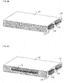
- FIG 3A a battery 10 with a first terminal 16 and a second terminal 17 is shown.
- the first terminal 16 and the second terminal 17 are arranged at a side surface of the battery 10.
- the first terminal 16 comprises two contacts 21 which are marked hatched.
- the second terminal 17 comprises one contact 21 which is marked solid.
- the contacts 21 of the first terminal 16 and of the second terminal 17 have the same shape.
- the first terminal 16 and the second terminal 17 are coplanar.
- the first terminal 16 and the second terminal 17 are coplanar in order to reduce the extent of the magnetic field induced by the current flowing through the terminals 16, 17.
- FIG 3B an alternative to arrange the first terminal 16 and the second terminal 17 at a side surface of the battery 10 is shown.
- Both terminals 16, 17 comprise three contacts 21.
- a contact 21 of the first terminal 16 is arranged between two contacts 21 of the second terminal 17 in a coplanar arrangement.
- a contact 21 of the second terminal 17 is arranged between two contacts 21 of the first terminal 16 in a coplanar arrangement.
- FIG 3C an alternative to arrange the first terminal 16 and the second terminal 17 at a side surface of the battery 10 is shown.
- the battery 10 comprises the same contacts 21 as shown in figure 10B and furthermore two contacts 21 at a further side surface of the battery 10.
- a contact 21 of the first terminal 16 and a contact 21 of the second terminal 17 are arranged next to each other in a coplanar arrangement.
- the currents at the first terminal 16 and at the second terminal 17 can be high. Therefore, it is advantageous to distribute the current over several electrical contacts 21.
- first terminal 16 and the second terminal 17 at a side surface of the battery 10 are shown.
- the contacts 21 of the first terminal 16 are marked hatched and the contacts 21 of the second terminal 17 are marked solid.
- the terminals 16, 17 are arranged coplanar or coaxial in order to reduce the extent of the magnetic field induced by the current flowing through the terminals 16, 17.
- the first terminal 16 comprises one contact 21 and the second terminal 17 comprises two contacts 21. All contacts 21 are rectangular shaped and arranged coplanar. The first terminal 16 is arranged between the two contacts 21 of the second terminal 17.
- the first terminal 16 and the second terminal 17 each comprise three contacts 21.
- a first contact 21 of the first terminal 16 is circular shaped.
- the first contact 21 of the first terminal 16 is surrounded by a ring-shaped contact 21 of the second terminal 17.
- a second contact 21 of the second terminal 17 is circular shaped.
- the second contact 21 of the second terminal 17 is surrounded by a ring-shaped contact 21 of the first terminal 16.
- a third contact 21 of the first terminal 16 is circular shaped.
- the third contact 21 of the first terminal 16 is surrounded by a ring-shaped contact 21 of the second terminal 17.
- the first terminal 16 comprises eight contacts 21 and the second terminal 17 comprises one contact 21. All contacts 21 are rectangular shaped. The contacts 21 of the first terminal 16 are coaxially arranged around the second terminal 17.
- the first terminal 16 comprises seven contacts 21 and the second terminal 17 comprises eight contacts 21. All contacts 21 are circular shaped.
- the contacts 21 of both terminals 16, 17 are arranged in an alternating structure, this means in a checkerboard structure.
- the first terminal 16 comprises eight contacts 21 and the second terminal 17 comprises two contacts 21. All contacts 21 are rectangular shaped. The contacts 21 of the first terminal 16 are coaxially arranged around the contacts 21 of the second terminal 17.
- the first terminal 16 comprises six contacts 21 and the second terminal 17 comprises one contact 21. All contacts 21 are rectangular shaped.
- the two terminals 16, 17 are arranged coplanar and the second terminal 17 is arranged between the contacts 21 of the first terminal 16.
- first terminal 16 and the second terminal 17 each comprise one contact 21.
- the first terminal 16 is rectangular shaped.
- the second terminal 17 is arranged as a stripe that surrounds the first terminal 16.
- the first terminal 16 comprises five contacts 21 and the second terminal 17 comprises one contact 21.
- the contacts 21 of the first terminal 16 are circular shaped and are arranged along a line at the side surface of the battery 10.
- the second terminal 17 is arranged as a stripe that surrounds the contacts 21 of the first terminal 16.
- the first terminal 16 comprises five contacts 21 and the second terminal 17 comprises eight contacts 21.
- the contacts 21 of the first terminal 16 are circular shaped and are arranged along a line at the side surface of the battery 10.
- the contacts 21 of the second terminal 17 are rectangular shaped and coaxially arranged around the contacts 21 of the first terminal 16.
- FIG 5A a side view of the battery 10 with the first terminal 16 and the second terminal 17 is shown.
- the contacts 21 of the first terminal 16 and the second terminal 17 are arranged as plugs.
- FIG 5B a side view of the battery 10 with the first terminal 16 and the second terminal 17 is shown.
- the contacts 21 of the first terminal 16 and the second terminal 17 are arranged as sockets.
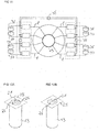
- FIG 6A another alternative to arrange the first terminal 16 and the second terminal 17 at a side surface of the battery 10 is shown.
- the first terminal 16 comprises several contacts 21 and the second terminal 17 comprises one contact 21.
- the contacts 21 of the first terminal 16 are arranged coaxially around the contact 21 of the second terminal 17.
- the two terminals 16, 17 are electrically isolated against each other.
- a clamp 27 is arranged around the terminals 16, 17 in order to induce force on an external terminal which can be connected to the battery 10. The induced force is indicated by the arrows. In this way the contact between the two terminals 16, 17 and the external terminal is improved and the contact resistance is decreased.
- FIG 6B another alternative to arrange the first terminal 16 and the second terminal 17 at a side surface of the battery 10 is shown.
- the only difference to the embodiment shown in figure 13A is that the external terminal can be fixed to the terminals 16, 17 of the battery 10 by screws 28.
- FIG 7A a plurality of battery cells 13 of a battery 10 for an electric vehicle is shown.
- a first group 36 comprises four battery cells 13 connected to each other in parallel.
- a second group 37 also comprises four battery cells 13 connected to each other in parallel.
- the first group 36 and the second group 37 are connected with each other in series forming a line 14. It is possible that further groups comprising battery cells 13 are connected in series with the first group 36 and the second group 37.
- the battery cells 13 can be for example lithium ion batteries with rated battery voltages between 3 and 4 V.
- the number of groups connected to each other in series can be kept small enough such that the battery voltage does not exceed a desired value and at the same time the capacity of the battery 10 is as high as required for an electric vehicle.
- the battery voltage can for example be at least 6 V and at most 60 V.
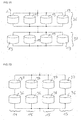
- FIG 7B four lines of battery cells 13 of a battery 10 for an electric vehicle are shown.
- a line 14 comprises a first group 36 and a second group 37 connected to each other in series.
- Three further lines 15 also comprises a first group 36 and a second group 37 connected to each other in series.
- the line 14 is connected to the further lines 15 in parallel.
- the number of groups 36, 37 connected in series to each other in each line can be kept small enough such that the battery voltage does not exceed a desired value and at the same time the capacity of the battery 10 is as high as required for an electric vehicle.
- each line comprises at least a first group 36 and a second group 37 of battery cells 13.
- a fuse 24 is connected to a circuit node of a line 14 and to a circuit node of a further line 15.
- Two further fuses 24 are connected to further circuit nodes of the line 14 and of the further line 15, respectively.
- the line currents I l in the different lines can be regulated such that all line currents I l are the same.
- a battery cell 13 or a group 36, 37 of battery cells 13 in the line 14 is defective a high line current I l can arise in the line 14.
- the fuses 24 it is avoided that the high line current I l also flows through further lines 15.
- the fuses 24 can for example be realized as shown in figure 8 or as positive temperature coefficient thermistors.
- Each battery module 22 comprises two lines 14, 15 each comprising two groups 36, 37 of battery cells 13.
- the line 14 and the further lines 15 are connected with each other in parallel by an electric line which can be for example an electric cable.
- the two battery modules 22 are connected with each other in parallel.
- FIG 9B two battery modules 22 and four lines 14, 15 are shown. Each line 14, 15 is distributed over the two battery modules 22. This means, a first group 36 of for example the line 14 is arranged in one battery module 22 and the second group 37 of the line 14 is arranged in the other battery module 22. The groups 36, 37 of each line are connected in series with each other. The four lines 14, 15 are connected to each other in parallel.
- FIG 10 shows an electrical circuit with four battery modules 22 connected to each other in parallel.
- Three of the battery modules 22 can be disconnected from the other battery modules 22 by a switch 35 which is connected in series with the respective battery module 22.
- each of these battery modules 22 is assigned a respective switch 35 to activate and/or deactivate the respective battery module 22.
- the first switch 35 on the lefthand side of the electrical circuit is a DC/DC converter.
- the second switch 35 is a mechanical switch and the third switch 35 is a semiconductor switch.
- the fourth battery module 22 cannot be disconnected by a respective switch 35. It is also possible that further battery modules 22 are connected to the four battery modules 22 in parallel.
- groups 36, 37 of battery cells 13 connected to the electric machine 33 of the electric vehicle are shown.
- the groups 36, 37 can be comprised by different battery modules 22 which are not shown.
- the groups 36, 37 are arranged in four different lines where each line comprises a first group 36 and a second group 37.
- the electric machine 33 comprises different electrical phases ⁇ .
- the electrical phases ⁇ can each be supplied with a respective phase current.
- the phase currents comprise an AC and a DC component.
- Each line is connected to two or more electrical phases ⁇ of the electric machine 33.
- the electrical phases ⁇ are short-circuited on a short circuit ring 29 of the electric machine 30. Therefore, the line currents I l are equalized if the groups 36, 37 of battery cells 13 are connected with the electrical phases ⁇ .
- the electric machine 33 is employed to equalize the line currents I l of the different lines of battery cells 13. As the electric machine 33 is controlled by the AC components of the phase currents the regulation of the line currents I l can take place both when the electric machine 33 is operated and when it is not operated.
- switches 35 are arranged between the lines. If single battery modules 22 can be exchanged and be replaced by charged battery modules 22 the charging level of the charged battery modules 22 and the battery modules 22 which are not replaced can be very different. This means, high compensation currents can arise.
- the line currents I l By regulating the line currents I l by coupling the battery modules 22 to the electric machine 33 the losses during regulation of the line currents I l are smaller in comparison to losses during a regulation of the line currents I l by passive elements as for example a positive temperature coefficient thermistor.
- FIG 12A a battery cell 13 with an electrical contact 21 is shown.
- the electrical contact 21 is a contact comprising a screw.
- the electrical contact 21 of the battery cell 13 is connected to a metal sheet 25.
- the metal sheet 25 can comprise aluminum or copper and it can connect several battery cells 13 with each other in parallel.
- the metal sheet 25 comprises a circular shaped hole around the electrical contact 21 except for two connections 26.
- the connections 26 act as fuses 24. If the current flowing from the battery cell 13 towards the metal sheet 25 is too high the two connections 26 will warm up and melt. For a better stability against for example torque exerted on the electrical contact 21 the metal sheet 25 comprises two connections 26 instead of only one.
- FIG 12B a battery cell 13 with an electrical contact 21 which is a welding contact is shown.
- the metal sheet 25 only comprises one connection 26 as a fuse 24 since no torque is exerted on the electrical contact 21.
- FIG 13 six battery cells 13 which are connected with metal sheets 25 are shown.
- Three battery cells 13 are connected with a metal sheet 25 on a top side of the battery cells 13 and with another metal sheet 25 on a bottom side of the battery cells 13 facing away from the top side.
- Three further battery cells 13 are also connected with a metal sheet 25 on the top side and with another metal sheet 25 on the bottom side of the battery cells 13.
- the two metal sheets 25 on the top side of the battery cells 13 are connected with each other by two thin connections 26.
- the two metal sheets 25 on the bottom side of the battery cells 13 are connected with each other by two thin connections 26.
- the connections 26 act as fuses 24 as described with figure 12A .
- the power system 32 comprises a circuit arrangement 11 as described above.
- the power system 32 further comprises an electric machine 33 and a power net 34, where the first output 18 is electrically coupled to the electric machine 33 and the second output 19 is electrically coupled to the power net 34.
- the battery 10 is configured to supply both the electric machine 33 and the power net 34 of the electric vehicle with power. Consequently, only one battery 10 is required for the electric vehicle.
- the power system 32 can be comprised by an electric vehicle.
- the power system is arranged to supply the electric vehicle with power, to enable movement of the electric vehicle and to enable the operation of the devices of the power net 34.
- the electric machine 33 and the power net 34 are supplied with the same voltage level by the battery 10, as neither between the first terminal 16 of the battery 10 and the first output 18 nor between the first terminal 16 and the second output 19 converters are arranged.
Abstract
Description
- The present application relates to a circuit arrangement for supplying an electric vehicle with power and to a power system for an electric vehicle.
- Electric vehicles with an electric machine or an electric motor require a battery with a large capacity in order to enable traveling over large distances. In order to achieve a large capacity of the battery it is common to connect a plurality of battery cells with a small capacity, as for example lithium ion batteries. When connecting the plurality of battery cells in series the battery voltage can amount to several hundreds of volts. For these high voltages a special isolation of the battery and other safety precautions are required.
- On the other hand other devices in the electric vehicle as for example the radio, a navigation system, lights or windscreen wipers, referred to as the power net of the electric vehicle, usually require a voltage which is smaller than 100 V.
- It is an objective to provide a circuit arrangement for supplying an electric vehicle with power and a power system which require less isolation and safety precautions. A further objective is to provide a circuit arrangement for supplying an electric vehicle with power and a power system which can supply both the electric machine and the power net of the electric vehicle with power.
- This objective is solved by the independent claims. Further embodiments are subject of dependent claims.
- In one embodiment of the circuit arrangement for supplying an electric vehicle with power, the circuit arrangement comprises a battery with a first terminal and a second terminal. The first and the second terminal can be electrical contacts where the battery can be electrically contacted and where a load can be connected. The battery can comprise a plurality of battery cells that are connected with each other. The battery cells can be for example lithium ion batteries.
- The electric vehicle can be any craft that can move on ground, in the air or on water. For example, the electric vehicle can be a car, an airplane or a boat.
- The circuit arrangement further comprises a reference potential terminal directly connected to the second terminal of the battery. This means, the battery and the reference potential terminal are electrically connected. The battery voltage is given relative to the reference potential.
- The circuit arrangement further comprises a first output that is coupled to the first terminal of the battery via a first switch and that is configured to be connected to an electric machine of the electric vehicle. The first output can be an electrical contact or an electrical terminal. The first output is electrically coupled to the first terminal of the battery via the first switch. The first terminal of the battery can be directly connected with the first switch and the first switch can be directly connected with the first output. With the first switch the connection between the battery and the electric machine can be activated and deactivated.
- The electric machine of the electric vehicle can be for example an electric motor. The movement of the electric vehicle can be driven by the electric machine and the electric machine is the main engine for traction of the electric vehicle. It is also possible that the electric machine comprises several electric machines or several electric motors. For example, the electric machine can comprise an electric machine for a front axle and a back axle of an electric vehicle, respectively. Furthermore, it is possible that the electric machine comprises four electric machines or four electric motors.
- That the first output is configured to be connected to an electric machine of the electric vehicle means that the first output can be electrically connected with the electric machine. If for example the electric machine comprises an electrical contact the first output can be electrically connected with the electrical contact of the electric machine. Preferably, the first output is configured to be connected to the electric machine in such a way that the electric machine can be supplied with power by the battery.
- The circuit arrangement further comprises a second output that is coupled to the first terminal of the battery and that is configured to be connected to a power net of the electric vehicle. The second output can be an electrical contact or an electrical terminal. The second output is electrically coupled to the first terminal of the battery. The power net of the electric vehicle is configured to supply other devices in the electric vehicle than the electric machine with power. The other devices in the electric vehicle can be for example the radio, loudspeakers, a navigation system, lights or windscreen wipers.
- The second output can be directly coupled to the first terminal of the battery. It is also possible that the second output is coupled to the first terminal of the battery via a second switch. The first terminal of the battery can be directly connected with the second switch and the second switch can be directly connected with the second output.
- That the second output is configured to be connected to the power net of the electric vehicle means that the second output can be electrically connected with the power net. If for example the power net comprises an electrical contact the second output can be electrically connected with the electrical contact of the power net. Preferably, the second output is configured to be connected to the power net in such a way that the power net can be supplied with power by the battery.
- The battery is configured to supply both the electric machine and the power net of the electric vehicle with power. Consequently, only one battery is required for the electric vehicle.
- Preferably, the electric machine and the power net are supplied with the same voltage level by the battery. This means, the electric machine and the power net are operated at the same voltage level. The same voltage level in this case means that it is approximately the same voltage level. However, the exact voltage level at the electrical contacts of the electric machine and the power net can slightly differ from the battery voltage because of losses in the circuit arrangement. The voltage level at the electrical contacts of the electric machine and the power net can also slightly differ from the battery voltage because of losses at switches or other components of the circuit arrangement.
- Advantageously, no converters to convert the battery voltage for the power net are required which is usually operated at smaller voltages than the electric machine.
- It is also possible that the power net comprises a sub power net which is operated at a voltage which is different from the battery voltage. For example at least a part of the power net can be operated at a voltage which is lower than the battery voltage. The sub power net can for example be operated at 12 V.
- In one embodiment of the circuit arrangement, the electric vehicle is at least one of:
- a craft that can move on ground,
- a craft that can move in the air,
- a craft that can move on and/or in water.
- In one embodiment of the circuit arrangement, the battery voltage which can be tapped between the first terminal and the second terminal of the battery is at most 60 V. Preferably, the battery voltage is at least 6 V. The battery voltage is a direct current (DC) voltage. For this voltage range it is possible that the battery is operated at separated extra low voltage and that it is compliant with standards defining the separated extra low voltage.
- In a preferred embodiment the rated battery voltage amounts to 48 V.
- Advantageously, less isolation and less safety precautions are required for these small battery voltages. Furthermore, a small battery voltage enables that the electric machine and the power net can both be supplied with power by the battery.
- In one embodiment of the circuit arrangement, the second output is directly and permanently coupled to the first terminal of the battery. This means, the second output is not coupled to the first terminal via a second switch but the second output is directly coupled to the first terminal. In this case the power net of the electric machine is permanently coupled to the battery.
- In one embodiment of the circuit arrangement, the second output is coupled to the first terminal of the battery via a second switch. The first terminal of the battery can be directly connected with the second switch and the second switch can be directly connected with the second output. With the second switch the connection between the battery and the power net can be activated and deactivated.
- In one embodiment of the circuit arrangement, the electric machine to which the first output is configured to be connected to is the traction engine of the electric vehicle. This means, the movement of the electric vehicle is driven by the electric machine and the electric machine is the main engine for traction of the vehicle. Preferably, the electric machine is the only traction engine of the electric vehicle and the electric vehicle does not comprise another traction engine as for example a petrol engine.
- In one embodiment of the circuit arrangement, the first switch comprises at least two sub-switches arranged in at least two parallel lines where the parallel lines are connected with each other by an inductive connection which comprises at least one inductivity. The term "line" refers to an electrical connection. Alternative expressions for "line" are line section, chain, string or strand. The at least two sub-switches can be mechanical or electro-mechanical switches or semiconductor switches. The at least two sub-switches are connected with each other in parallel. This means at least two lines comprising each a sub-switch are connected with each other in parallel. The at least two lines are connected with each other by an inductive connection. The inductive connection can be an electrical connection between the at least two lines. That the inductive connection comprises at least one inductivity means that the at least two lines are connected with each other via the inductivity. The inductivity can comprise a first electrical contact which is connected to one of the at least two lines. The inductivity further can comprise a second electrical contact which is connected to another one of the at least two lines. The inductivity comprises an inductor as for example a coil.
- The at least two sub-switches of the first switch are usually opened with small time delays. In order to avoid that the current from the battery towards the first output only flows through the sub-switch which is opened at last the inductivities allow compensation currents between the sub- switches and avoid rapidly rising currents in the first switch.
- In one embodiment of the circuit arrangement, the first terminal and the second terminal of the battery are coplanar or coaxial. The first and the second terminal can for example be arranged at an outer surface of the battery. For example, the first and the second terminal can comprise the same or a similar shape. Advantageously, the first terminal and the second terminal are coplanar or coaxial in order to reduce the extent of the magnetic field induced by the current flowing through the terminals.
- In one embodiment of the circuit arrangement, the first terminal and/or the second terminal of the battery comprise at least two contacts, respectively. The at least two contacts of the first and/or the second terminal can be arranged next to each other or on top of each other. It is also possible that the at least two contacts of the first and/or the second terminal are arranged at different side surfaces of the battery. As the battery voltage is small, the currents at the first and the second terminal can be high. Therefore, it is advantageous to distribute the current over several electrical contacts.
- In one embodiment of the circuit arrangement, the first terminal and the second terminal of the battery are arranged coaxial. Also in this way the extent of the magnetic field induced by the current flowing through the terminals is reduced.
- In one embodiment of the circuit arrangement, the first terminal and/or the second terminal of the battery are arranged as plugs. In another embodiment of the circuit arrangement, the first terminal and/or the second terminal of the battery are arranged as sockets.
- In one embodiment of the circuit arrangement, the battery comprises at least one line of battery cells, where a first group comprises a plurality of battery cells connected to each other in parallel, a second group comprises a plurality of battery cells connected to each other in parallel, and the first group and the second group are connected with each other in series forming the line of battery cells.
- The battery cells can be for example lithium ion batteries with rated cell voltages between 3 and 4 V. The battery cells each comprise electrical contacts via which they can be electrically contacted. This means, in the first group and in the second group the battery cells are connected in parallel in an electrical circuit, respectively. The first group and the second group are connected in series in an electrical circuit.
- The term "line" refers to a plurality of battery cells electrically connected to each other. Each line comprises at least a first group and a second group that are connected with each other in series. Alternative expressions for "line" are line section, chain, string or strand.
- It is possible that further groups of battery cells are connected in series with the first group and the second group. Also the further groups comprise a plurality of battery cells connected to each other in parallel.
- The battery cells are arranged in such a way that a small battery voltage is enabled. A small battery voltage can be for example a voltage which is equal to or smaller than 60 V.
- The number of battery cells connected with each other in the first group and in the second group, respectively, are chosen in such a way that the capacity of the battery is as high as required for an electric vehicle. At the same time, the number of groups connected to each other in series is kept small enough such that the battery voltage does not exceed a desired value.
- Therefore, the battery is configured in such a way that the battery voltage is small. This means, the battery voltage can be for example below a set maximum value.
- Advantageously, less isolation and less safety precautions are required for small battery voltages. Furthermore, the electric machine and the power net are both supplied with power by the battery. No converters are required to convert the battery voltage for the power net which is usually operated at small voltages.
- In one embodiment of the circuit arrangement, the line is connected to at least one further line in parallel, where the further line comprises the same features as the line, and a fuse is connected to a circuit node of the line and to a circuit node of the further line. This means, the further line comprises at least one first group and at least one second group of battery cells. The line and the at least one further line are connected with each other in parallel in an electrical circuit.
- By connecting the line and at least one further line in parallel to each other the capacity of the battery is increased. Consequently, the number of groups connected in series to each other in each line can be kept small enough such that the battery voltage does not exceed a desired value and at the same time the capacity of the battery is as high as required for an electric vehicle.
- Due to slight differences between the battery cells the currents in the different lines, referred to as line currents, can differ from each other. Consequently, the battery cells in a line with a higher line current are discharged more than battery cells in a line with a smaller line current. This means, the battery cells that are discharged more are degrading and aging faster than the other battery cells. Furthermore, it is possible that compensation currents arise if the power consumed by for example the electric machine or another load changes with time. By employing the fuse the different line currents can be regulated such that all line currents are the same or very similar. Furthermore, if for example a battery cell in a line is defective a high line current can arise in the line. With the fuse it is avoided that the high line current also flows through further lines.
- In one embodiment of the circuit arrangement, the fuse is a positive temperature coefficient thermistor. In the case of high line currents the resistance of the positive temperature coefficient thermistor increases such that the high line current cannot flow from the line to the further line. If the line current decreases again the positive temperature coefficient thermistor cools down again and the resistance decreases.
- In one embodiment of the circuit arrangement, the battery comprises at least two battery modules. This means, the battery cells of the battery are distributed over the at least two battery modules. Every battery module comprises a plurality of battery cells. By distributing the battery cells to the different battery modules it is possible to arrange the different battery modules at different places in the electric vehicle. Therefore, all places in the electric vehicle where there is space for battery modules can be used.
- Moreover, the battery modules can be configured to be exchanged separately from each other. This means, at least some of the battery modules can be removed from the electric vehicle and be replaced by for example charged battery modules. For example, battery modules that are arranged in easily accessible places of the electric vehicle as the trunk can be exchanged. In this way, a driver or a user of the electric vehicle does not have to wait until all battery modules are recharged before continuing to drive but the driver or the user can exchange some battery modules which takes less time than recharging all battery modules.
- In one embodiment of the circuit arrangement, the at least two battery modules are configured to be electrically coupled to the electric machine of the electric vehicle. In this embodiment the electric machine is employed to equalize the line currents of the different lines of the battery. If an electric machine comprises different electrical phases each line is electrically connected to one or more electrical phases. By supplying the electrical phases with different DC currents the line currents can be regulated and equalized. As the electric machine is controlled by AC currents of the different electrical phases the regulation of the line currents can take place both when the electric machine is operated and when it is not operated since the line currents are regulated only by DC currents. Alternatively, it is possible to employ the electric machine partially in motor mode and partially in generator mode for regulating the line currents.
- If single battery modules can be exchanged and be replaced by charged battery modules the charging level of the charged battery modules and the battery modules which are not replaced can be very different. This means, high compensation currents can arise. By regulating the line currents by coupling the battery modules to the electric machine the losses during regulation of the line currents are smaller in comparison to losses during a regulation of the line currents by passive elements as for example a positive temperature coefficient thermistor.
- In one embodiment of the circuit arrangement, the at least two battery modules are arranged in parallel and each battery module is assigned a respective switch to activate and/or deactivate the respective battery module. The switch can be for example a DC/DC converter, an electro mechanical switch, a semiconductor switch or an electrical switch. In this way, the battery modules can be arranged in different places of the electric vehicle and the risk of a local damage of the battery is reduced as a damaged battery module can be disconnected from the other battery modules by the respective switch.
- In addition, a power system for an electric vehicle is provided.
- In one embodiment of the power system for an electric vehicle, the power system comprises an embodiment of the circuit arrangement as described above.
- The power system further comprises an electric machine and a power net, where the first output is electrically coupled to the electric machine and the second output is electrically coupled to the power net. This means, the battery is configured to supply both the electric machine and the power net of the electric vehicle with power. Consequently, only one battery is required for the electric vehicle.
- The power system can be comprised by an electric vehicle. The power system is arranged to supply the electric vehicle with power, to enable movement of the electric vehicle and to enable the operation of the devices of the power net.
- Preferably, the battery voltage is at least 6 V and at most 60 V. For example, the rated battery voltage amounts to 48 V. Advantageously, less isolation and less safety precautions are required for these small battery voltages. Furthermore, a small battery voltage enables that the electric machine and the power net can both be supplied with power by the battery of the power system.
- In one embodiment of the power system, the electric machine and the power net are supplied with the same voltage level by the battery. This means, the electric machine and the power net are operated at the same voltage level. The same voltage level in this case means that it is approximately the same voltage level. However, the exact voltage level at the electrical contacts of the electric machine and the power net can slightly differ from the battery voltage because of losses in the circuit arrangement. The voltage level at the electrical contacts of the electric machine and the power net can also slightly differ from the battery voltage because of losses at switches or other components of the circuit arrangement.
- It is also possible that the power net comprises a sub power net which is operated at a voltage which is different from the battery voltage. For example at least a part of the power net can be operated at a voltage which is lower than the battery voltage. The sub power net can for example be operated at 12 V.
- Advantageously, no converters to convert the battery voltage for the power net are required which is usually operated at smaller voltages than the electric machine.
- In one embodiment of the power system, the electric machine is only powered by the battery. This means, the movement of the electric vehicle is driven by the electric machine and the electric machine is the main engine for traction of the vehicle. The power system and the electric vehicle do not comprise another source of power for the electric machine than the battery. Preferably, the electric machine is the only traction engine of the electric vehicle and the electric vehicle does not comprise another traction engine as for example a petrol engine.
- The following description of figures may further illustrate and explain exemplary embodiments. Components that are functionally identical or have an identical effect are denoted by identical references. Identical or effectively identical components might be described only with respect to the figures where they occur first. Their description is not necessarily repeated in successive figures.
- In
figures 1A, 1B and1C different embodiments of the circuit arrangement are shown. - In
figure 2 an embodiment of the first switch is shown. - In
figures 3A ,3B ,3C ,4A, 4B, 4C, 4D, 4E, 4F, 4G ,4H ,4I, 5A, 5B, 6A and 6B electrical contacts of the battery are shown. - In
figure 7A a first group and a second group of battery cells are shown. - In
figures 7B and8 four lines of battery cells are shown. - In
figures 9A and9B two battery modules are depicted. -
Figure 10 shows an electrical circuit with battery modules connected to each other in parallel. - In
figure 11 battery cells connected to the electric machine are shown. - With
figures 12A, 12B and13 fuses for battery cells are described. - In
figure 14 an embodiment of the power system is shown. - In
figure 1A an embodiment of acircuit arrangement 11 for supplying an electric vehicle with power is shown. Thecircuit arrangement 11 comprises abattery 10 with afirst terminal 16 and asecond terminal 17. Thefirst terminal 16 and thesecond terminal 17 can be electrical contacts where thebattery 10 can be electrically contacted and where a load can be connected. Thesecond terminal 17 of thebattery 10 is directly connected to a referencepotential terminal 12. The battery voltage is given in relation to the reference potential. The referencepotential terminal 12 is connected to a further referencepotential terminal 12. - The
first terminal 16 of thebattery 10 is coupled to afirst output 18 via afirst switch 20. In this embodiment thefirst switch 20 is a semiconductor switch. Thefirst output 18 is configured to be connected to anelectric machine 33 of the electric vehicle. Asecond output 19 is coupled to thefirst terminal 16 of thebattery 10 via an electric line or an electric cable. Thesecond output 19 is configured to be connected to apower net 34 of the electric vehicle. - Electric lines or cables crossing each other in the figures are electrically isolated against each other. Electric lines or cables which are connected with a connection point in the figures are electrically connected with each other.
- That the
first output 18 is configured to be connected to anelectric machine 33 of the electric vehicle means that thefirst output 18 can be electrically connected with theelectric machine 33. If for example theelectric machine 33 comprises an electrical contact thefirst output 18 can be electrically connected with the electrical contact of theelectric machine 33. Preferably, thefirst output 18 is configured to be connected to theelectric machine 33 in such a way that theelectric machine 33 can be supplied with power by thebattery 10. - That the
second output 19 is configured to be connected to thepower net 34 of the electric vehicle means that thesecond output 19 can be electrically connected with thepower net 34. If for example thepower net 34 comprises an electrical contact thesecond output 19 can be electrically connected with the electrical contact of thepower net 34. Preferably, thesecond output 19 is configured to be connected to thepower net 34 in such a way that thepower net 34 can be supplied with power by thebattery 10. - The
battery 10 is configured to supply both theelectric machine 33 and thepower net 34 of the electric vehicle with power. Consequently, only onebattery 10 is required for the electric vehicle. - In
figure 1B a further embodiment of thecircuit arrangement 11 is shown. In this embodiment thesecond output 19 is coupled to thefirst terminal 16 of thebattery 10 via asecond switch 23. Thesecond switch 23 is a semiconductor switch. It is also possible that thesecond switch 23 is any other type of switch. Thefirst switch 20 is an electro-mechanical switch. It is also possible that thefirst switch 20 is any other type of switch. - In
figure 1C a further embodiment of thecircuit arrangement 11 is shown. In this embodiment thesecond switch 23 is a DC/DC converter. Advantageously, with a DC/DC converter thesecond output 19 can be completely decoupled from thebattery 10 and thefirst output 18. - In
figure 2 an embodiment of thefirst switch 20 is shown. Thefirst switch 20 comprises threesub-switches 30 that are connected with each other in parallel. Thus, the threesub-switches 30 are arranged in three parallel lines where the parallel lines are connected with each other by an inductive connection which comprises aninductivity 31, respectively. The sub-switches 30 can be mechanical or electro-mechanical switches or semiconductor switches. The inductive connection is an electrical connection between the three lines. That the inductive connections comprise aninductivity 31 means that the three lines are connected with each other via theinductivity 31. Theinductivity 31 comprises an inductor as for example a coil. - The
sub-switches 30 of thefirst switch 20 are usually opened with small time delays. In order to avoid that the current from thebattery 10 towards thefirst output 18 only flows through the sub-switch 30 which is opened at last theinductivities 31 allow compensation currents between the sub-switches 30 and avoid rapidly rising currents in thefirst switch 20. - In
figure 3A abattery 10 with afirst terminal 16 and asecond terminal 17 is shown. Thefirst terminal 16 and thesecond terminal 17 are arranged at a side surface of thebattery 10. Thefirst terminal 16 comprises twocontacts 21 which are marked hatched. Thesecond terminal 17 comprises onecontact 21 which is marked solid. Thecontacts 21 of thefirst terminal 16 and of thesecond terminal 17 have the same shape. Thefirst terminal 16 and thesecond terminal 17 are coplanar. Advantageously, thefirst terminal 16 and thesecond terminal 17 are coplanar in order to reduce the extent of the magnetic field induced by the current flowing through theterminals - In
figure 3B an alternative to arrange thefirst terminal 16 and thesecond terminal 17 at a side surface of thebattery 10 is shown. Bothterminals contacts 21. Acontact 21 of thefirst terminal 16 is arranged between twocontacts 21 of thesecond terminal 17 in a coplanar arrangement. Moreover, acontact 21 of thesecond terminal 17 is arranged between twocontacts 21 of thefirst terminal 16 in a coplanar arrangement. - In
figure 3C an alternative to arrange thefirst terminal 16 and thesecond terminal 17 at a side surface of thebattery 10 is shown. Thebattery 10 comprises thesame contacts 21 as shown in figure 10B and furthermore twocontacts 21 at a further side surface of thebattery 10. At the further side surface acontact 21 of thefirst terminal 16 and acontact 21 of thesecond terminal 17 are arranged next to each other in a coplanar arrangement. As the battery voltage is small, the currents at thefirst terminal 16 and at thesecond terminal 17 can be high. Therefore, it is advantageous to distribute the current over severalelectrical contacts 21. - In
figures 4A to 4I nine alternatives to arrange thefirst terminal 16 and thesecond terminal 17 at a side surface of thebattery 10 are shown. Thecontacts 21 of thefirst terminal 16 are marked hatched and thecontacts 21 of thesecond terminal 17 are marked solid. In all embodiments theterminals terminals - In
figure 4A thefirst terminal 16 comprises onecontact 21 and thesecond terminal 17 comprises twocontacts 21. Allcontacts 21 are rectangular shaped and arranged coplanar. Thefirst terminal 16 is arranged between the twocontacts 21 of thesecond terminal 17. - In
figure 4B thefirst terminal 16 and thesecond terminal 17 each comprise threecontacts 21. Afirst contact 21 of thefirst terminal 16 is circular shaped. Thefirst contact 21 of thefirst terminal 16 is surrounded by a ring-shapedcontact 21 of thesecond terminal 17. Asecond contact 21 of thesecond terminal 17 is circular shaped. Thesecond contact 21 of thesecond terminal 17 is surrounded by a ring-shapedcontact 21 of thefirst terminal 16. Athird contact 21 of thefirst terminal 16 is circular shaped. Thethird contact 21 of thefirst terminal 16 is surrounded by a ring-shapedcontact 21 of thesecond terminal 17. - In
figure 4C thefirst terminal 16 comprises eightcontacts 21 and thesecond terminal 17 comprises onecontact 21. Allcontacts 21 are rectangular shaped. Thecontacts 21 of thefirst terminal 16 are coaxially arranged around thesecond terminal 17. - In
figure 4D thefirst terminal 16 comprises sevencontacts 21 and thesecond terminal 17 comprises eightcontacts 21. Allcontacts 21 are circular shaped. Thecontacts 21 of bothterminals - In
figure 4E thefirst terminal 16 comprises eightcontacts 21 and thesecond terminal 17 comprises twocontacts 21. Allcontacts 21 are rectangular shaped. Thecontacts 21 of thefirst terminal 16 are coaxially arranged around thecontacts 21 of thesecond terminal 17. - In
figure 4F thefirst terminal 16 comprises sixcontacts 21 and thesecond terminal 17 comprises onecontact 21. Allcontacts 21 are rectangular shaped. The twoterminals second terminal 17 is arranged between thecontacts 21 of thefirst terminal 16. - In
figure 4G thefirst terminal 16 and thesecond terminal 17 each comprise onecontact 21. Thefirst terminal 16 is rectangular shaped. Thesecond terminal 17 is arranged as a stripe that surrounds thefirst terminal 16. - In
figure 4H thefirst terminal 16 comprises fivecontacts 21 and thesecond terminal 17 comprises onecontact 21. Thecontacts 21 of thefirst terminal 16 are circular shaped and are arranged along a line at the side surface of thebattery 10. Thesecond terminal 17 is arranged as a stripe that surrounds thecontacts 21 of thefirst terminal 16. - In
figure 4I thefirst terminal 16 comprises fivecontacts 21 and thesecond terminal 17 comprises eightcontacts 21. Thecontacts 21 of thefirst terminal 16 are circular shaped and are arranged along a line at the side surface of thebattery 10. Thecontacts 21 of thesecond terminal 17 are rectangular shaped and coaxially arranged around thecontacts 21 of thefirst terminal 16. - In
figure 5A a side view of thebattery 10 with thefirst terminal 16 and thesecond terminal 17 is shown. Thecontacts 21 of thefirst terminal 16 and thesecond terminal 17 are arranged as plugs. - In
figure 5B a side view of thebattery 10 with thefirst terminal 16 and thesecond terminal 17 is shown. Thecontacts 21 of thefirst terminal 16 and thesecond terminal 17 are arranged as sockets. - In
figure 6A another alternative to arrange thefirst terminal 16 and thesecond terminal 17 at a side surface of thebattery 10 is shown. Thefirst terminal 16 comprisesseveral contacts 21 and thesecond terminal 17 comprises onecontact 21. Thecontacts 21 of thefirst terminal 16 are arranged coaxially around thecontact 21 of thesecond terminal 17. The twoterminals clamp 27 is arranged around theterminals battery 10. The induced force is indicated by the arrows. In this way the contact between the twoterminals - In
figure 6B another alternative to arrange thefirst terminal 16 and thesecond terminal 17 at a side surface of thebattery 10 is shown. The only difference to the embodiment shown in figure 13A is that the external terminal can be fixed to theterminals battery 10 byscrews 28. - In
figure 7A a plurality ofbattery cells 13 of abattery 10 for an electric vehicle is shown. Afirst group 36 comprises fourbattery cells 13 connected to each other in parallel. Asecond group 37 also comprises fourbattery cells 13 connected to each other in parallel. Thefirst group 36 and thesecond group 37 are connected with each other in series forming aline 14. It is possible that further groups comprisingbattery cells 13 are connected in series with thefirst group 36 and thesecond group 37. Thebattery cells 13 can be for example lithium ion batteries with rated battery voltages between 3 and 4 V. - The number of groups connected to each other in series can be kept small enough such that the battery voltage does not exceed a desired value and at the same time the capacity of the
battery 10 is as high as required for an electric vehicle. The battery voltage can for example be at least 6 V and at most 60 V. - In
figure 7B four lines ofbattery cells 13 of abattery 10 for an electric vehicle are shown. Aline 14 comprises afirst group 36 and asecond group 37 connected to each other in series. Threefurther lines 15 also comprises afirst group 36 and asecond group 37 connected to each other in series. Theline 14 is connected to thefurther lines 15 in parallel. - The number of
groups battery 10 is as high as required for an electric vehicle. - In
figure 8 four lines are connected to each other in parallel. Each line comprises at least afirst group 36 and asecond group 37 ofbattery cells 13. Afuse 24 is connected to a circuit node of aline 14 and to a circuit node of afurther line 15. Two further fuses 24 are connected to further circuit nodes of theline 14 and of thefurther line 15, respectively. In this way, the line currents Il in the different lines can be regulated such that all line currents Il are the same. Furthermore, if for example abattery cell 13 or agroup battery cells 13 in theline 14 is defective a high line current Il can arise in theline 14. With thefuses 24 it is avoided that the high line current Il also flows throughfurther lines 15. Thefuses 24 can for example be realized as shown infigure 8 or as positive temperature coefficient thermistors. - In
figure 9A twobattery modules 22 are shown. Eachbattery module 22 comprises twolines groups battery cells 13. Theline 14 and thefurther lines 15 are connected with each other in parallel by an electric line which can be for example an electric cable. Moreover, the twobattery modules 22 are connected with each other in parallel. - By distributing the
groups battery cells 13 to thedifferent battery modules 22 it is possible to arrange thedifferent battery modules 22 at different places in the electric vehicle. Therefore, all places in the vehicle where there is space forbattery modules 22 can be used. - In
figure 9B twobattery modules 22 and fourlines line battery modules 22. This means, afirst group 36 of for example theline 14 is arranged in onebattery module 22 and thesecond group 37 of theline 14 is arranged in theother battery module 22. Thegroups lines - If all lines of the
battery 10 are comprised by at least twobattery modules 22 temperature differences between thebattery modules 22 and different contact resistances ofdifferent battery modules 22 are experienced by all lines in the same way. Therefore, differences in capacity or voltage of the lines due to external parameters as the temperature or contact resistances of thebattery modules 22 are avoided. -
Figure 10 shows an electrical circuit with fourbattery modules 22 connected to each other in parallel. Three of thebattery modules 22 can be disconnected from theother battery modules 22 by aswitch 35 which is connected in series with therespective battery module 22. This means, each of thesebattery modules 22 is assigned arespective switch 35 to activate and/or deactivate therespective battery module 22. Thefirst switch 35 on the lefthand side of the electrical circuit is a DC/DC converter. Thesecond switch 35 is a mechanical switch and thethird switch 35 is a semiconductor switch. Thefourth battery module 22 cannot be disconnected by arespective switch 35. It is also possible thatfurther battery modules 22 are connected to the fourbattery modules 22 in parallel. - In
figure 11 groups battery cells 13 connected to theelectric machine 33 of the electric vehicle are shown. Thegroups different battery modules 22 which are not shown. Thegroups first group 36 and asecond group 37. Theelectric machine 33 comprises different electrical phases ϕ. The electrical phases ϕ can each be supplied with a respective phase current. The phase currents comprise an AC and a DC component. Each line is connected to two or more electrical phases ϕ of theelectric machine 33. The electrical phases ϕ are short-circuited on ashort circuit ring 29 of theelectric machine 30. Therefore, the line currents Il are equalized if thegroups battery cells 13 are connected with the electrical phases ϕ. - This means, the
electric machine 33 is employed to equalize the line currents Il of the different lines ofbattery cells 13. As theelectric machine 33 is controlled by the AC components of the phase currents the regulation of the line currents Il can take place both when theelectric machine 33 is operated and when it is not operated. - In order to exchange
battery modules 22, switches 35 are arranged between the lines. Ifsingle battery modules 22 can be exchanged and be replaced by chargedbattery modules 22 the charging level of the chargedbattery modules 22 and thebattery modules 22 which are not replaced can be very different. This means, high compensation currents can arise. By regulating the line currents Il by coupling thebattery modules 22 to theelectric machine 33 the losses during regulation of the line currents Il are smaller in comparison to losses during a regulation of the line currents Il by passive elements as for example a positive temperature coefficient thermistor. - In
figure 12A abattery cell 13 with anelectrical contact 21 is shown. Theelectrical contact 21 is a contact comprising a screw. Theelectrical contact 21 of thebattery cell 13 is connected to ametal sheet 25. Themetal sheet 25 can comprise aluminum or copper and it can connectseveral battery cells 13 with each other in parallel. Themetal sheet 25 comprises a circular shaped hole around theelectrical contact 21 except for twoconnections 26. Theconnections 26 act as fuses 24. If the current flowing from thebattery cell 13 towards themetal sheet 25 is too high the twoconnections 26 will warm up and melt. For a better stability against for example torque exerted on theelectrical contact 21 themetal sheet 25 comprises twoconnections 26 instead of only one. - In
figure 12B abattery cell 13 with anelectrical contact 21 which is a welding contact is shown. In this case themetal sheet 25 only comprises oneconnection 26 as afuse 24 since no torque is exerted on theelectrical contact 21. - In
figure 13 sixbattery cells 13 which are connected withmetal sheets 25 are shown. Threebattery cells 13 are connected with ametal sheet 25 on a top side of thebattery cells 13 and with anothermetal sheet 25 on a bottom side of thebattery cells 13 facing away from the top side. Threefurther battery cells 13 are also connected with ametal sheet 25 on the top side and with anothermetal sheet 25 on the bottom side of thebattery cells 13. The twometal sheets 25 on the top side of thebattery cells 13 are connected with each other by twothin connections 26. Similarly, the twometal sheets 25 on the bottom side of thebattery cells 13 are connected with each other by twothin connections 26. Theconnections 26 act asfuses 24 as described withfigure 12A . - In
figure 14 an embodiment of thepower system 32 is shown. Thepower system 32 comprises acircuit arrangement 11 as described above. Thepower system 32 further comprises anelectric machine 33 and apower net 34, where thefirst output 18 is electrically coupled to theelectric machine 33 and thesecond output 19 is electrically coupled to thepower net 34. This means, thebattery 10 is configured to supply both theelectric machine 33 and thepower net 34 of the electric vehicle with power. Consequently, only onebattery 10 is required for the electric vehicle. - The
power system 32 can be comprised by an electric vehicle. The power system is arranged to supply the electric vehicle with power, to enable movement of the electric vehicle and to enable the operation of the devices of thepower net 34. - Advantageously, the
electric machine 33 and thepower net 34 are supplied with the same voltage level by thebattery 10, as neither between thefirst terminal 16 of thebattery 10 and thefirst output 18 nor between thefirst terminal 16 and thesecond output 19 converters are arranged. -
- 10:
- battery
- 11:
- circuit arrangement
- 12:
- reference potential terminal
- 13:
- battery cell
- 14:
- line
- 15:
- further line
- 16:
- first terminal
- 17:
- second terminal
- 18:
- first output
- 19:
- second output
- 20:
- first switch
- 21:
- contact
- 22:
- battery module
- 23:
- second switch
- 24:
- fuse
- 25:
- metal sheet
- 26:
- connection
- 27:
- clamp
- 28:
- screw
- 29:
- short circuit ring
- 30:
- sub-switch
- 31:
- inductivity
- 32:
- power system
- 33:
- electric machine
- 34:
- power net
- 35:
- switch
- 36:
- first group
- 37:
- second group
- Il:
- line current
- ϕ:
- electrical phase
Claims (18)
- Circuit arrangement (11) for supplying an electric vehicle with power, the circuit arrangement (11) comprising:- a battery (10) with a first terminal (16) and a second terminal (17),- a reference potential terminal (12) directly connected to the second terminal (17) of the battery (10),- a first output (18) that is coupled to the first terminal (16) of the battery (10) via a first switch (20) and that is configured to be connected to an electric machine (33) of the electric vehicle, and- a second output (19) that is coupled to the first terminal (16) of the battery (10) and that is configured to be connected to a power net (34) of the electric vehicle.
- Circuit arrangement (11) according to the preceding claim, where the electric vehicle is at least one of:- a craft that can move on ground,- a craft that can move in the air,- a craft that can move on and/or in water.
- Circuit arrangement (11) according to one of the preceding claims, where the battery voltage which can be tapped between the first terminal (16) and the second terminal (17) of the battery (10) is at most 60 V.
- Circuit arrangement (11) according to one of the preceding claims, where the second output (19) is directly and permanently coupled to the first terminal (16) of the battery (10).
- Circuit arrangement (11) according to one of claims 1 to 3, where the second output (19) is coupled to the first terminal (16) of the battery (10) via a second switch (23).
- Circuit arrangement (11) according to one of the preceding claims, where the electric machine (33) to which the first output (18) is configured to be connected to is the traction engine of the electric vehicle.
- Circuit arrangement (11) according to one of the preceding claims, where the first switch (20) comprises at least two sub-switches (30) arranged in at least two parallel lines where the parallel lines are connected with each other by an inductive connection which comprises at least one inductivity (31).
- Circuit arrangement (11) according to one of the preceding claims, where the first terminal (16) and the second terminal (17) of the battery (10) are coplanar or coaxial.
- Circuit arrangement (11) according to one of the preceding claims, where the first terminal (16) and/or the second terminal (17) of the battery (10) comprise at least two contacts (21), respectively.
- Circuit arrangement (11) according to one of the preceding claims, where the battery (10) comprises at least one line (14) of battery cells (11), where a first group (36) comprises a plurality of battery cells (11) connected to each other in parallel, a second group (37) comprises a plurality of battery cells (11) connected to each other in parallel, and the first group (36) and the second group (37) are connected with each other in series forming the line (14) of battery cells (11).
- Circuit arrangement (11) according to the preceding claim, where the line (14) is connected to at least one further line (15) in parallel, where the further line (15) comprises the same features as the line (14), and a fuse (24) is connected to a circuit node of the line (14) and to a circuit node of the further line (15).
- Circuit arrangement (11) according to the preceding claim, where the fuse (24) is a positive temperature coefficient thermistor.
- Circuit arrangement (11) according to one of the preceding claims, where the battery (10) comprises at least two battery modules (22).
- Circuit arrangement (11) according to the preceding claim, where the at least two battery modules (22) are configured to be electrically coupled to the electric machine (33) of the electric vehicle.
- Circuit arrangement (11) according to one of claims 13 or 14, where the at least two battery modules (22) are arranged in parallel and each battery module (22) is assigned a respective switch (35) to activate and/or deactivate the respective battery module (22).
- Power system (32) for an electric vehicle, the power system (32) comprising- a circuit arrangement (11) according to one of the preceding claims,- an electric machine (33), and- a power net (34),where the first output (18) is coupled to the electric machine (33) and the second output (19) is coupled to the power net (34).
- Power system (32) according to the preceding claim, where the electric machine (33) and the power net (34) are supplied with the same voltage level by the battery (10).
- Power system (32) according to one of claims 16 or 17, where the electric machine (33) is only powered by the battery (10).
Priority Applications (4)
| Application Number | Priority Date | Filing Date | Title |
|---|---|---|---|
| EP17169961.4A EP3402031A1 (en) | 2017-05-08 | 2017-05-08 | Circuit arrangement and power system |
| CN201880029921.7A CN110651408A (en) | 2017-05-08 | 2018-05-02 | Circuit device and power system |
| US16/609,759 US11673479B2 (en) | 2017-05-08 | 2018-05-02 | Circuit arrangement and power system |
| PCT/EP2018/061194 WO2018206366A1 (en) | 2017-05-08 | 2018-05-02 | Circuit arrangement and power system |
Applications Claiming Priority (1)
| Application Number | Priority Date | Filing Date | Title |
|---|---|---|---|
| EP17169961.4A EP3402031A1 (en) | 2017-05-08 | 2017-05-08 | Circuit arrangement and power system |
Publications (1)
| Publication Number | Publication Date |
|---|---|
| EP3402031A1 true EP3402031A1 (en) | 2018-11-14 |
Family
ID=58672519
Family Applications (1)
| Application Number | Title | Priority Date | Filing Date |
|---|---|---|---|
| EP17169961.4A Pending EP3402031A1 (en) | 2017-05-08 | 2017-05-08 | Circuit arrangement and power system |
Country Status (4)
| Country | Link |
|---|---|
| US (1) | US11673479B2 (en) |
| EP (1) | EP3402031A1 (en) |
| CN (1) | CN110651408A (en) |
| WO (1) | WO2018206366A1 (en) |
Citations (3)
| Publication number | Priority date | Publication date | Assignee | Title |
|---|---|---|---|---|
| EP1641066A2 (en) * | 2004-09-22 | 2006-03-29 | Howaldtswerke-Deutsche Werft GmbH | Battery plant of a submarine |
| US20130113495A1 (en) * | 2011-09-28 | 2013-05-09 | Alliance For Sustainable Energy, Llc | Fail-Safe Designs for Large Capacity Battery Systems |
| US20160272191A1 (en) * | 2015-03-20 | 2016-09-22 | GM Global Technology Operations LLC | Method of controlling a powertrain of a vehicle |
Family Cites Families (12)
| Publication number | Priority date | Publication date | Assignee | Title |
|---|---|---|---|---|
| JP2944095B2 (en) * | 1988-03-11 | 1999-08-30 | ブラック アンド デッカー インコーポレイティド | Battery case and charger for battery type tool |
| WO2001069784A1 (en) * | 2000-03-15 | 2001-09-20 | Ct-Concept Technologie Ag | Method for operating a parallel arrangement of power semiconductor switches |
| EP1313193A1 (en) | 2001-11-19 | 2003-05-21 | Dialog Semiconductor GmbH | Battery protection system with sequential blowing fuse |
| JP3776348B2 (en) * | 2001-12-10 | 2006-05-17 | 本田技研工業株式会社 | Vehicle power supply |
| JP4127705B2 (en) * | 2005-10-07 | 2008-07-30 | 日本航空電子工業株式会社 | Electrical connector |
| US7671565B2 (en) | 2006-02-13 | 2010-03-02 | Tesla Motors, Inc. | Battery pack and method for protecting batteries |
| US8467891B2 (en) * | 2009-01-21 | 2013-06-18 | Utc Fire & Security Americas Corporation, Inc. | Method and system for efficient optimization of audio sampling rate conversion |
| US9793889B2 (en) * | 2011-03-15 | 2017-10-17 | Infineon Technologies Ag | Semiconductor device including a circuit to compensate for parasitic inductance |
| JPWO2012132435A1 (en) * | 2011-03-29 | 2014-07-24 | パナソニック株式会社 | Vehicle power supply |
| FR2979770B1 (en) * | 2011-09-01 | 2013-09-13 | Converteam Technology Ltd | HIGH POWER CONVERTER WITH LOW POWER TRANSISTORS CONNECTED IN PARALLEL |
| WO2016113798A1 (en) * | 2015-01-16 | 2016-07-21 | ソニー株式会社 | Electrical storage module, electrical storage system, electronic equipment, electric car and electric power system |
| US11529859B2 (en) * | 2016-04-01 | 2022-12-20 | Faraday & Future Inc. | Electric vehicle battery management |
-
2017
- 2017-05-08 EP EP17169961.4A patent/EP3402031A1/en active Pending
-
2018
- 2018-05-02 WO PCT/EP2018/061194 patent/WO2018206366A1/en active Application Filing
- 2018-05-02 US US16/609,759 patent/US11673479B2/en active Active
- 2018-05-02 CN CN201880029921.7A patent/CN110651408A/en active Pending
Patent Citations (3)
| Publication number | Priority date | Publication date | Assignee | Title |
|---|---|---|---|---|
| EP1641066A2 (en) * | 2004-09-22 | 2006-03-29 | Howaldtswerke-Deutsche Werft GmbH | Battery plant of a submarine |
| US20130113495A1 (en) * | 2011-09-28 | 2013-05-09 | Alliance For Sustainable Energy, Llc | Fail-Safe Designs for Large Capacity Battery Systems |
| US20160272191A1 (en) * | 2015-03-20 | 2016-09-22 | GM Global Technology Operations LLC | Method of controlling a powertrain of a vehicle |
Also Published As
| Publication number | Publication date |
|---|---|
| CN110651408A (en) | 2020-01-03 |
| US20200062134A1 (en) | 2020-02-27 |
| WO2018206366A1 (en) | 2018-11-15 |
| US11673479B2 (en) | 2023-06-13 |
Similar Documents
| Publication | Publication Date | Title |
|---|---|---|
| US10828994B2 (en) | Battery system with battery control | |
| US10596917B2 (en) | Vehicle and electrical system with dual battery modules | |
| JP6346887B2 (en) | Battery charge balance | |
| US11063308B2 (en) | Battery for an electric vehicle | |
| CN108215873A (en) | Charging unit | |
| JP2013518369A (en) | Charging contact array that enables parallel charging and discharging of batteries | |
| US9537132B2 (en) | Battery having a plurality of battery modules arranged in battery strings, and method for operating the battery | |
| US8907628B2 (en) | Automotive bipolar electrical system | |
| US20210078429A1 (en) | Electric powertrain with multi-pack battery system | |
| US11063462B2 (en) | Charging apparatus | |
| IT201900001099A1 (en) | GROUP AND METHOD OF CHARGING AND POWER SUPPLY FOR AN ELECTRIC VEHICLE, AND ELECTRIC VEHICLE INCLUDING THE CHARGING AND POWER UNIT | |
| WO2010107381A1 (en) | System and method for controlling an energe storage pack | |
| US11673479B2 (en) | Circuit arrangement and power system | |
| JP2019161721A (en) | Vehicular power supply system | |
| US10232728B2 (en) | Electrochemical composite storage system | |
| US10744899B2 (en) | Balancing energy in a parallelized battery system | |
| CN111038419A (en) | Configurable vehicle power outlet system | |
| CN219592158U (en) | Charging and discharging circuit, battery control circuit and electric equipment | |
| JP2019134635A (en) | Charge and discharge device and charge and discharge system | |
| KR20190063065A (en) | Low voltage dc-dc converter with a built-in battery | |
| US10978953B2 (en) | Flyback power supply, inverter and electrically powered vehicle | |
| CN116937085A (en) | Battery pack with parallel conductor wiring | |
| Garnier et al. | Battery System and Battery Management System (BMS) | |
| KR20240043239A (en) | Power control unit for electric vehicle | |
| CN115703376A (en) | Charging system, battery system and method for operating a battery system |
Legal Events
| Date | Code | Title | Description |
|---|---|---|---|
| PUAI | Public reference made under article 153(3) epc to a published international application that has entered the european phase |
Free format text: ORIGINAL CODE: 0009012 |
|
| STAA | Information on the status of an ep patent application or granted ep patent |
Free format text: STATUS: THE APPLICATION HAS BEEN PUBLISHED |
|
| AK | Designated contracting states |
Kind code of ref document: A1 Designated state(s): AL AT BE BG CH CY CZ DE DK EE ES FI FR GB GR HR HU IE IS IT LI LT LU LV MC MK MT NL NO PL PT RO RS SE SI SK SM TR |
|
| AX | Request for extension of the european patent |
Extension state: BA ME |
|
| STAA | Information on the status of an ep patent application or granted ep patent |
Free format text: STATUS: REQUEST FOR EXAMINATION WAS MADE |
|
| 17P | Request for examination filed |
Effective date: 20190508 |
|
| RBV | Designated contracting states (corrected) |
Designated state(s): AL AT BE BG CH CY CZ DE DK EE ES FI FR GB GR HR HU IE IS IT LI LT LU LV MC MK MT NL NO PL PT RO RS SE SI SK SM TR |
|
| RAP1 | Party data changed (applicant data changed or rights of an application transferred) |
Owner name: MOLABO GMBH |
|
| STAA | Information on the status of an ep patent application or granted ep patent |
Free format text: STATUS: EXAMINATION IS IN PROGRESS |
|
| 17Q | First examination report despatched |
Effective date: 20210514 |
|
| STAA | Information on the status of an ep patent application or granted ep patent |
Free format text: STATUS: EXAMINATION IS IN PROGRESS |