EP3402017A1 - Light-emitting device - Google Patents
Light-emitting device Download PDFInfo
- Publication number
- EP3402017A1 EP3402017A1 EP16883528.8A EP16883528A EP3402017A1 EP 3402017 A1 EP3402017 A1 EP 3402017A1 EP 16883528 A EP16883528 A EP 16883528A EP 3402017 A1 EP3402017 A1 EP 3402017A1
- Authority
- EP
- European Patent Office
- Prior art keywords
- light
- phosphor
- emitting device
- wavelength converter
- wavelength
- Prior art date
- Legal status (The legal status is an assumption and is not a legal conclusion. Google has not performed a legal analysis and makes no representation as to the accuracy of the status listed.)
- Withdrawn
Links
Images

Classifications
-
- H—ELECTRICITY
- H01—ELECTRIC ELEMENTS
- H01S—DEVICES USING THE PROCESS OF LIGHT AMPLIFICATION BY STIMULATED EMISSION OF RADIATION [LASER] TO AMPLIFY OR GENERATE LIGHT; DEVICES USING STIMULATED EMISSION OF ELECTROMAGNETIC RADIATION IN WAVE RANGES OTHER THAN OPTICAL
- H01S5/00—Semiconductor lasers
- H01S5/005—Optical components external to the laser cavity, specially adapted therefor, e.g. for homogenisation or merging of the beams or for manipulating laser pulses, e.g. pulse shaping
- H01S5/0087—Optical components external to the laser cavity, specially adapted therefor, e.g. for homogenisation or merging of the beams or for manipulating laser pulses, e.g. pulse shaping for illuminating phosphorescent or fluorescent materials, e.g. using optical arrangements specifically adapted for guiding or shaping laser beams illuminating these materials
-
- F—MECHANICAL ENGINEERING; LIGHTING; HEATING; WEAPONS; BLASTING
- F21—LIGHTING
- F21V—FUNCTIONAL FEATURES OR DETAILS OF LIGHTING DEVICES OR SYSTEMS THEREOF; STRUCTURAL COMBINATIONS OF LIGHTING DEVICES WITH OTHER ARTICLES, NOT OTHERWISE PROVIDED FOR
- F21V9/00—Elements for modifying spectral properties, polarisation or intensity of the light emitted, e.g. filters
- F21V9/30—Elements containing photoluminescent material distinct from or spaced from the light source
- F21V9/32—Elements containing photoluminescent material distinct from or spaced from the light source characterised by the arrangement of the photoluminescent material
-
- F—MECHANICAL ENGINEERING; LIGHTING; HEATING; WEAPONS; BLASTING
- F21—LIGHTING
- F21V—FUNCTIONAL FEATURES OR DETAILS OF LIGHTING DEVICES OR SYSTEMS THEREOF; STRUCTURAL COMBINATIONS OF LIGHTING DEVICES WITH OTHER ARTICLES, NOT OTHERWISE PROVIDED FOR
- F21V9/00—Elements for modifying spectral properties, polarisation or intensity of the light emitted, e.g. filters
- F21V9/30—Elements containing photoluminescent material distinct from or spaced from the light source
- F21V9/38—Combination of two or more photoluminescent elements of different materials
-
- G—PHYSICS
- G02—OPTICS
- G02B—OPTICAL ELEMENTS, SYSTEMS OR APPARATUS
- G02B6/00—Light guides; Structural details of arrangements comprising light guides and other optical elements, e.g. couplings
-
- G—PHYSICS
- G02—OPTICS
- G02B—OPTICAL ELEMENTS, SYSTEMS OR APPARATUS
- G02B6/00—Light guides; Structural details of arrangements comprising light guides and other optical elements, e.g. couplings
- G02B6/0001—Light guides; Structural details of arrangements comprising light guides and other optical elements, e.g. couplings specially adapted for lighting devices or systems
- G02B6/0005—Light guides; Structural details of arrangements comprising light guides and other optical elements, e.g. couplings specially adapted for lighting devices or systems the light guides being of the fibre type
-
- F—MECHANICAL ENGINEERING; LIGHTING; HEATING; WEAPONS; BLASTING
- F21—LIGHTING
- F21Y—INDEXING SCHEME ASSOCIATED WITH SUBCLASSES F21K, F21L, F21S and F21V, RELATING TO THE FORM OR THE KIND OF THE LIGHT SOURCES OR OF THE COLOUR OF THE LIGHT EMITTED
- F21Y2115/00—Light-generating elements of semiconductor light sources
- F21Y2115/30—Semiconductor lasers
-
- H—ELECTRICITY
- H01—ELECTRIC ELEMENTS
- H01S—DEVICES USING THE PROCESS OF LIGHT AMPLIFICATION BY STIMULATED EMISSION OF RADIATION [LASER] TO AMPLIFY OR GENERATE LIGHT; DEVICES USING STIMULATED EMISSION OF ELECTROMAGNETIC RADIATION IN WAVE RANGES OTHER THAN OPTICAL
- H01S5/00—Semiconductor lasers
- H01S5/02—Structural details or components not essential to laser action
- H01S5/022—Mountings; Housings
- H01S5/0225—Out-coupling of light
- H01S5/02251—Out-coupling of light using optical fibres
-
- H—ELECTRICITY
- H01—ELECTRIC ELEMENTS
- H01S—DEVICES USING THE PROCESS OF LIGHT AMPLIFICATION BY STIMULATED EMISSION OF RADIATION [LASER] TO AMPLIFY OR GENERATE LIGHT; DEVICES USING STIMULATED EMISSION OF ELECTROMAGNETIC RADIATION IN WAVE RANGES OTHER THAN OPTICAL
- H01S5/00—Semiconductor lasers
- H01S5/30—Structure or shape of the active region; Materials used for the active region
- H01S5/32—Structure or shape of the active region; Materials used for the active region comprising PN junctions, e.g. hetero- or double- heterostructures
- H01S5/323—Structure or shape of the active region; Materials used for the active region comprising PN junctions, e.g. hetero- or double- heterostructures in AIIIBV compounds, e.g. AlGaAs-laser, InP-based laser
- H01S5/32308—Structure or shape of the active region; Materials used for the active region comprising PN junctions, e.g. hetero- or double- heterostructures in AIIIBV compounds, e.g. AlGaAs-laser, InP-based laser emitting light at a wavelength less than 900 nm
- H01S5/32341—Structure or shape of the active region; Materials used for the active region comprising PN junctions, e.g. hetero- or double- heterostructures in AIIIBV compounds, e.g. AlGaAs-laser, InP-based laser emitting light at a wavelength less than 900 nm blue laser based on GaN or GaP
Definitions
- the present invention relates to a light-emitting device.
- light-emitting devices each being a combination of a solid-state light-emitting element that emits laser light and a wavelength converter containing phosphors.
- Such light-emitting devices include a light-emitting device by which the wavelength or spectrum of emitted light is changed to a desired wavelength as a result of the combination of a solid-state light-emitting element and phosphors in accordance with the application.
- Patent Literature 1 has proposed a light-emitting device that utilizes a single crystal phosphor causing a small degree of temperature quenching.
- the light-emitting color of the phosphors gets darker in the surrounding portion (diagonally above the solid-state light-emitting element), and this causes unevenness in the color of the output light.
- a light-emitting device that is a combination of a solid-state light-emitting element that emits laser light of bluish color and YAG phosphors that absorb the laser light and perform wavelength conversion into yellowish light
- the center of output light has darker blue and the surrounding portion has darker yellow. This problem is particularly significant in a light-emitting device that utilizes a single crystal phosphor having high transmissivity for laser light.
- the present invention is conceived to overcome the above-described problem, and has an object to provide a light-emitting device that produces less unevenness in the color of output light.
- one aspect of the light-emitting device is a light-emitting device that emits output light and includes: a radiation source that radiates laser light as first primary light; and a first wavelength converter.
- the first wavelength converter includes at least a first phosphor.
- the first wavelength converter scatters at least part of the first primary light and converts into second primary light that propagates in a direction different from an optical-axis direction of the first primary light.
- the first phosphor included in the first wavelength converter absorbs at least part of the first primary light and the second primary light and converts into secondary light.
- the secondary light has more long-wavelength components than a wavelength component of at least one of the first primary light or the second primary light, and the output light includes the second primary light and the secondary light.
- the first wavelength converter has an incidence face on which the first primary light is incident and an emission face through which the output light emits, and a normal to the incidence face and a normal to the emission face are mutually different.
- the first phosphor is a single crystal phosphor.
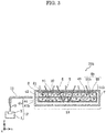
- FIG. 3 is a schematic view of a light-emitting device according to Variation 1 of Embodiment 2.
- light-emitting device 21 is a device that includes radiation source 2 which emits laser light as 1-1 light 3, and first wavelength converter 4, and emits output light 31. Stated differently, 1-1 light 3 is first primary light.
- First wavelength converter 4 scatters at least part of 1-1 light 3 and converts into 1-2 light 5 that propagates in a direction different from the optical-axis direction of 1-1 light 3. Stated differently, 1-2 light 5 is second primary light. In addition, first wavelength converter 4 absorbs at least part of 1-1 light 3 and 1-2 light 5 and converts into secondary light 6.
- light-emitting device 21 has a rectangular shape, radiation source 2 is located in the vicinity of one face of the rectangular shape, and a direction approximately vertical to the face on which radiation source 2 is located corresponds to the optical-axis direction of 1-1 light 3. Radiation source 2 receives power necessary for emitting 1-1 light 3, for example, by being electrically connected to external power source 1.
- Light-emitting device 21 defines the optical-axis direction of 1-1 light 3 to be an x-axis. Moreover, directions mutually orthogonal in a plane orthogonal to the x-axis are defined to be a y-axis and a z-axis, respectively.
- the size of light-emitting device 21 is, for example, within a size defined by 100 mm in an x-axis direction, 30 mm in a y-axis direction, and 100 mm in a z-axis direction.
- Radiation source 2 emits laser light as 1-1 light 3.
- a laser diode such as a surface emitting laser diode, for example, can be used as such radiation source 2.
- Radiation source 2 is connected to external power source 1.
- Radiation source 2 is, for example, a solid-state light-emitting element. Such a configuration allows the size of radiation source 2 to be smaller and this enables reduction in the size of light-emitting device 21.
- Radiation source 2 may radiate bluish light having an emission spectrum indicating a maximum peak intensity in the wavelength range of, for example, at least 420 nm and at most 480 nm or at least 440 nm and at most 470 nm.
- 1-1 light 3 has a maximum peak intensity in the wavelength rage as described above, 1-1 light 3 becomes visually recognizable blue light and 1-2 light 5 which is a scattered component of 1-1 light 3 also becomes visually recognizable blue light.
- 1-2 light 5 can be therefore used, without waste, not only as excitation light that excites first phosphors 41, but also as output light 31 of light-emitting device 21.
- radiation source 2 may radiate, as 1-1 light 3, ultraviolet light having an emission spectrum indicating a maximum peak intensity in the wavelength range of, for example, at least 200 nm and at most 380 nm or at least 360 nm and at most 380 nm. Furthermore, radiation source 2 may radiate, as 1-1 light 3, purplish light having an emission spectrum indicating a maximum peak intensity in the wavelength range of, for example, at least 200 nm and at most 380 nm or at least 395 nm and at most 415 nm.
- a blue phosphor can be selected as first phosphor 41.
- first phosphor 41 blue light that has a broad spectrum of light emitted by first phosphor 41 can be used as part of output light 31.
- the spectrum of light emitted from a phosphor has a broader spectrum width (FWHM: Full Width at Half Maximum) than laser light.
- First wavelength converter 4 has a flat plate shape and is disposed in such a manner that the y-axis direction of light-emitting device 21 is approximately parallel to the thickness direction of first wavelength converter 4.
- Such a structure allows first wavelength converter 4 to have a shape identical to the shape of a wavelength converter practically qualified over a long manufacturing history. It is therefore possible to use readily procurable and high-quality first wavelength converter 4, and to provide light-emitting device 21 that emits highly reliable output light 31.
- First wavelength converter 4 is provided in a position where 1-1 light 3 is irradiated from radiation source 2.
- First wavelength converter 4 includes first phosphors 41.
- first wavelength converter 4 includes only first phosphors 41, and first phosphor 41 is composed of one single crystal phosphor having a garnet crystal structure.
- First wavelength converter 4 has incidence face 42 on which 1-1 light 3 is incident and emission face 43 through which output light 31 emits.
- a normal to incidence face 42 and a normal to emission face 43 are mutually different.
- the normal to incidence face 42 and the normal to emission face 43 may be approximately vertical to each other.
- First wavelength converter 4 scatters at least part of 1-1 light 3 and propagates 1-2 light 5 which is a scattered component of 1-1 light 3.
- at least part of 1-1 light 3 may be scattered by defects in an interface portion between incidence face 42 and emission face 43 or by at least one portion where refractive indices are different in first wavelength converter 4.
- Wavelength converter 4 is configured so that 1-2 light 5 emits through emission face 43.
- first wavelength converter 4 absorbs at least part of 1-1 light 3 and 1-2 light 5 and converts into secondary light 6.
- Wavelength converter 4 is configured so that secondary light 6 emits through emission face 43.
- First phosphor 41 is included in first wavelength converter 4, absorbs at least part of 1-1 light 3 and 1-2 light 5, as excitation light, and emits, as secondary light 6, a phosphor containing more long-wavelength components than a wavelength component of at least one of 1-1 light 3 or 1-2 light 5.
- first phosphor 41 has a garnet structure. With such a structure, first phosphor 41 becomes chemically stable, and it is therefore possible to provide a light-emitting device with good reliability.
- a garnet structure is expressed by a general formula A' 3 B' 2 (C'X 4 ) 3 . It should be noted that A', B' and C' denote metallic elements that may possibly have a garnet structure whereas X denotes a nonmetal element that may possibly have a garnet structure.
- the metal element A' is, for example, at least one element selected from alkali metals, alkaline earth metals, magnesium, rare earths, and transition metals. More specifically, the metal element A' is at least one element selected, for example, from Na, K, Rb, Cs, Mg, Ca, Sr, Ba, Y, Ln, and Mn (Ln represents lanthanoid having atomic numbers from 57 to 71).
- the metal element B' is, for example, at least one element selected from Mg, rare earths, transition metals, alkaline earth metals, magnesium, and carbon-family elements. More specifically, the metal element B' is, at least one element selected, for example, from Mg, Sc, Y, Lu, Ti, Zr, Hf, V, Cr, Nb, Fe, Co, Ni, Cu, Zn, Al, Ga, In, and Sn.
- the metal element C' is, for example, at least one element selected from alkali metals, transition metals, alkaline earth metals, magnesium, carbon-family elements, and nitrogen-family elements. More specifically, the metal element C' is at least one element selected, for example, from Li, V, Fe, Al, Ga, Si, Ge, and P.
- the nonmetal element X is, for example, at least one element selected from nitrogen, chalcogen, and halogen. More specifically, the nonmetal element X is at least one element selected, for example, from N, O, F, and Cl.
- First phosphor 41 is, for example, a Ce 3+- activated phosphor. With such a feature, first phosphor 41 becomes an ultrashort afterglow phosphor, and it is therefore possible to provide a light-emitting device that experiences a small amount of efficiency saturation when first phosphor 41 is excited with high-density light.
- Radiation source 2 may radiate, as secondary light 6, light having a spectrum indicating a maximum peak intensity in the wavelength range of, for example, at least 480 nm and at most 600 nm.
- first phosphor 41 emits secondary light 6 having high luminous efficacy in a visible light range. Therefore, by using secondary light 6 as part of output light 31, it is possible to provide light-emitting device 21 that emits high-luminous-flux output light 31.
- a Ce 3+- activated phosphor having a garnet structure is, for example, any of the following phosphors.
- a cyan Ce 3+- activated phosphor having a garnet structure is, for example, Ca 2 YZ r2 (AlO 4 ) 3 :Ce 3+ .
- the cyan Ce 3+- activated phosphor is a Ce 3+- activated phosphor that emits light having an emission peak in the wavelength range of at least 480 nm and less than 500 nm.
- a green Ce 3+- activated phosphor having a garnet structure is, for example, Lu 3 Al 2 (AlO 4 ) 3 :Ce 3+ , Lu 3 (Al, Ga) 2 (AlO 4 ) 3 :Ce 3+ , (Y, Lu) 3 Al 2 (AlO 4 ) 3 :Ce 3+ , Y 3 Al 2 (AlO 4 ) 3 :Ce 3+ , Y 3 Ga 2 (AlO 4 ) 3 :Ce 3+ , or Ca 3 Sc 2 (SiO 4 ) 3 :Ce 3+ .
- the green Ce 3+- activated phosphor is a Ce 3+- activated phosphor that emits light having an emission peak in the wavelength range of at least 500 nm and less than 560 nm and, in particular, at least 510 nm and less than 550 nm.
- Lu 3 Al 2 (AlO 4 ) 3 :Ce 3+ and Lu 3 (Al, Ga) 2 (AlO 4 ) 3 :Ce 3+ each have a small degree of temperature quenching as compared with Y 3 Ga 2 (AlO 4 ) 3 :Ce 3+ , and therefore hold a high efficiency level even when the temperature of phosphors increases due to the primary light being excited with high-density light. Accordingly, with the use of Lu 3 Al 2 (AlO 4 ) 3 :Ce 3+- activated green phosphor, it is possible to easily achieve a light-emitting device having increased efficiency in the output of green light components. Lu 3 Al 2 (AlO 4 ) 3 :Ce 3+ is therefore useful as a phosphor intended for illumination.
- a yellowish-green-to-yellow-to-orange Ce 3+- activated phosphor having a garnet structure is, for example, (Y, Gd) 3 Al 2 (AlO 4 ) 3 :Ce 3+ .
- the yellowish-green-to-yellow-to-orange Ce 3+- activated phosphor is a Ce 3+- activated phosphor that emits light having an emission peak in the wavelength range of at least 560 nm and less than 600 nm.
- An oxide phosphor such as oxide or oxide halogen that is activated by at least one ion selected from among Eu 2+ , Ce 3+ , and Mn 2+ , or a nitride phosphor such as nitride and oxynitride can be used as a blue phosphor.
- BaMgAl 10 O 17 :Eu 2+ , BaMgAl 10 O 17 :Eu 2+ , Mn 2+ , CaMgSi 2 O 6 :Eu 2+ , Ba 3 MgSi 2 O 8 :Eu 2+ , Sr 4 Al 14 O 25 :Eu 2+ , Sr 4 Si 3 O 8 Cl 4 :Eu 2+ , Sr 4 Al 14 O 24 :Eu 2+ , BaAl 8 O 13 :Eu 2+ , Na 3 Sc 2 (PO 4 ) 3 :Eu 2+ , and Sr 10 (PO 4 ) 6 C 12 :Eu 2+ are raised as the examples of oxide phosphor whereas AlN:Eu 2+ , YSiO 2 N:Ce 3+ and SrSi 9 Al 19 ON 31 :Eu 2+ are raised as the examples of nitride phosphor.
- First phosphor 41 may be, for example, a single crystal phosphor.
- a single crystal is a particle or a structure such that a direction of a crystal axis does not change depending on the position of a crystal. With such a structure, first phosphor 41 has less internal defects, and it is therefore possible to provide light-emitting device 21 with which less loss is caused due to first phosphor 41 in wavelength conversion.
- the methods for growing first phosphor 41 include, for example, solid phase methods, liquid phase methods, and vapor phase methods.
- the liquid phase methods include, for example, melt growth techniques such as a Czochralski method, a simple solidification method, a Bridgman method, a Verneuil method, and a floating zone method, and also include solution methods such as a flux method, an aqueous solution method, and a hydrothermal method.
- First phosphor 41 may be a piece obtained by cutting a grown single crystal into arbitrary-shaped pieces. With such a structure, it is possible to provide light-emitting device 21 capable of easy control over an area of emission face 43 of output light 31 and the emitting direction of output light 31.
- first phosphor 41 may have irregularities. With such a feature, it is less probable that total reflection occurs inside a crystal when excitation light is incident on first phosphor 41, and therefore, it is possible to provide high-power light-emitting device 21 having high efficiency in the wavelength conversion performed by first phosphor 41.
- Reflector 7 is disposed in such a manner to cover at least one face other than incidence face 42 and emission face 43, of light, of first wavelength converter 4.
- the directions of least part of 1-1 light 3, 1-2 light 5, and secondary light 6 that propagate inside first wavelength converter 4 are controlled by reflector 7. With such a feature, less optical components that are emitted or absorbed through a face other than emission face 43 of first wavelength converter 4. It is therefore possible to provide light-emitting device 21 having high efficiency in the extraction of output light 31.
- Reflector 7 is made, for example, of metal such as aluminum, a white inorganic compound such as barium sulfate, or a white resin such as polyester.
- first wavelength converter 4 has a flat plate shape, and a direction that is approximately vertical to incidence face 42 of first wavelength converter 4 approximately corresponds to a direction that is approximately vertical to the thickness direction of first wavelength converter 4. With such a feature, the area of emission face 43 of first wavelength converter 4 gets larger with respect to the incidence area of first wavelength converter 4, therefore, it is possible to provide light-emitting device 21 having a large light emitting area.
- 1-1 light 3 may be incident on incidence face 42, for example, in a direction approximately vertical to the thickness direction of first wavelength converter 4, and output light 31 may emit through emission face 43, for example, in a direction approximately parallel to the thickness direction of first wavelength converter 4.
- the area of emission face 43 of first wavelength converter 4 gets larger with respect to the incidence area, therefore, it is possible to provide light-emitting device 21 having a large light emitting area.
- Secondary light 6 is a component obtained by converting the wavelength of at least part of 1-1 light 3 and 1-2 light 5 by first wavelength converter 4.
- Output light 31 includes 1-2 light 5 and secondary light 6.
- the correlated color temperature of output light 31 is, for example, at least 2000 K and at most 20000 K or at least 2500 K and at most 7000 K.
- the color of output light 31 becomes whitish, and it is therefore possible to achieve light-emitting device 21 that has a high utility value.
- the correlated color temperature of output light 31 of light-emitting device 21 in the range of at least 2500 K and at most 7000 K, it is possible to achieve light-emitting device 21 that emits light desirable as illumination light.
- any of the following methods can be used to define the correlated color temperature of output light 31 of light-emitting device 21 to be in the range of at least 2000 K and at most 20000 K: a method of selecting the laser light source to be used as radiation source 2; a method of selecting the type of first phosphor 41 included in first wavelength converter 4; and a method of adjusting the amount of first phosphors 41 included in first wavelength converter 4.
- Output light 31 can be used as illumination light.
- light-emitting device 21 has a structure including a closed space enclosed by cover 8 and light exit window 81.
- Cover 8 has a connection portion to be connected with external power source 1, and is formed, for example, by way of injection molding using a resin material such as an ABS resin.
- Light exit window 81 is provided at a portion facing emission face 43 and is formed by a transparent material such as resin or glass.
- the closed space enclosed by cover 8 and light exit window 81 may be a vacuum space or may be filled with air, nitrogen, rare gas, or a transparent material such as resin or glass.
- cover 8 and light exit window 81 has, for example, a highly hermetically sealed structure.
- the closed space enclosed by cover 8 and light exit window 81 is filled with air or a transparent material, the closed space may be conducted to the exterior.
- Light-emitting device 21a according to Embodiment 2 is different from light-emitting device 21 according to Embodiment 1 in the components such as second wavelength converter 9, second phosphors 91, tertiary light 10, and output light 31a.
- the components other than these listed are identical to those included in light-emitting device 21 according to Embodiment 1, therefore, the descriptions of the identical components are omitted.
- second wavelength converter 9 is located on emission face 43 of first wavelength converter 4, and is configured to absorb at least part of 1-2 light 5 and secondary light 6.
- Second wavelength converter 9 includes at least second phosphors 91, absorbs at least part of 1-2 light 5 and secondary light 6 and converts into tertiary light 10.
- second wavelength converter 9 is at least one particle and the particle has a central particle diameter of at least 0.1 ⁇ m and at most 1 mm.
- the shape of second wavelength converter 9 can be selected from among a spherical shape, a hemispherical shape, an acicular shape, etc.
- second wavelength converter 9 may be a film-shaped (filmy) wavelength converter.
- Second phosphors 91 are each included in second wavelength converter 9, absorbs at least part of 1-2 light 5 and secondary light 6, as excitation light, and emits tertiary light 10 in the form of fluorescence.
- second wavelength converter 9 includes only second phosphors 91.
- Second phosphor 91 may be a phosphor that is activated, for example, by a transition metal ion or a rare earth ion.
- the transition metal ion may be at least one ion selected, for example, from Ti 4+ , Cr 3+ , Mn 2+ , Mn 4+ , and Fe 3+ , among which Mn 4+ is a representative example thereof.
- the rare earth ion may be at least one ion selected, for example, from Ce 3+ , Pr 3+ , Nd 3+ , Sm 3+ , Eu 2+ , Eu 3+ , Tb 3+ , Dy 3+ , Ho 3+ , Er 3+ , Tm 3+ , and Yb 3+ .
- a phosphor activated by Mn 4+ may be, for example, an oxide phosphor such as 3.5MgO ⁇ 0.5MgF 2 ⁇ GeO 2 :Mn 4+ or a fluoride phosphor such as K 2 SiF 6 :Mn 4+ .
- second phosphor 91 is able to absorb at least part of 1-2 light 5 and secondary light 6, and emit tertiary light 10 in the form of fluorescence.
- Second phosphor 91 emits, as tertiary light 10, light having a spectrum indicating a maximum peak intensity in the wavelength range of, for example, at least 480 nm and at most 660 nm.
- tertiary light 10 has a large amount of visible light components having a long wavelength. Therefore, by using tertiary light 10 as part of output light 31a, it is possible to provide light-emitting device 21a desirably intended for illumination having high color rendering properties.
- the spectrum of the light emitted by second phosphor 91 may be different from the spectrum of the light emitted by first phosphor 41.
- the wavelength component of light that cannot be achieved exclusively by first phosphor 41 can be used as part of output light 31a. It is thus possible to provide light-emitting device 21a capable of easy control over the spectrum of output light 31a.
- the principal component of the spectrum of the light emitted by second phosphor 91 may contain more long-wavelength components than the principal component of the spectrum of the light emitted by first phosphor 41.
- tertiary light 10 has a large amount of visible light components having a long wavelength, and it is therefore possible to provide light-emitting device 21a that emits output light 31a having high color rendering properties.
- the spectrum of the light emitted by second phosphor 91 may be identical to the spectrum of the light emitted by first phosphor 41. With such a feature, it is possible, without changing the spectrum of output light 31a, to provide light-emitting device 21a having high light extraction efficiency.
- second phosphor 91 may be, for example, a Ce 3+- activated phosphor. With such a feature, tertiary light 10 emitted by second phosphor 91 becomes an ultrashort afterglow phosphor. It is therefore possible to provide a light-emitting device that experiences a small amount of efficiency saturation when second phosphor 91 is excited with high-density light.
- second phosphor 91 may be one of a nitride phosphor or an oxynitride phosphor that emits reddish light having a spectrum indicating a maximum peak intensity in the wavelength range of at least 600 nm and at most 660 nm.
- the nitride phosphor may be, for example, Sr 2 Si 5 N 8 :Eu 2+ , (Ca, Sr) AlSiN 3 :Eu 2+ , SrAlSi 4 N 7 :Eu 2+ , and SrLiAl 3 N 4 :Eu 2+ .
- the oxynitride phosphor is, for example, Sr 2 (Si, Al) 5 (N, O) 8 :Eu 2+ , CaAl(Si, Al)(N, O) 3 :Eu 2+ , and SrAl(Si, Al) 4 (N, O) 7 :Eu 2+ .
- second phosphor 91 is chemically stable, has high excitation light absorptance, and becomes capable of efficiently performing wavelength conversion of absorbed excitation light into light having a longer wavelength than the absorbed excitation light. With such a feature, second phosphor 91 comes to emit a reddish light component, and it is therefore possible to provide light-emitting device 21a capable of emitting output light 31a having high color rendering properties.
- Second phosphor 91 may be, for example, a compound having a crystal structure identical to that of CaAlSiN 3 . With such a feature, second phosphors 91 are each a phosphor having been practically proved as a phosphor for LED illumination. Therefore, by using a readily procurable second phosphor 91, it is possible to provide light-emitting device 21a that emits high-power and highly reliable output light 31a.
- Tertiary light 10 is a component obtained by converting the wavelength of at least part of 1-2 light 5 and secondary light 6 by second wavelength converter 9.
- Output light 31a includes 1-2 light 5, secondary light 6, and tertiary light 10.
- Average color rendering index Ra of output light 31a may be at least 80 and at most 100. When average color rendering index Ra of output light 31a of light-emitting device 21a is in this range, it is possible to achieve light-emitting device 21a that emits light desirable as illumination light. Any of the following methods can be used to define the range of average color rendering index Ra of output light 31a of light-emitting device 21a to be within the above-described range: a method of selecting the laser light source to be used as radiation source 2; a method of selecting the type of first phosphor 41 included in first wavelength converter 4; and a method of selecting the type of second phosphor 91 included in second phosphor 9.
- light-emitting device 21b according to Variation 1 will be described with reference to FIG. 3 .
- the following describes components characterizing light-emitting device 21b, focusing on differences between light-emitting device 21b and light-emitting device 21a according to aforementioned Embodiment 2. As for the other components, they are identical to those included in light-emitting device 21a.
- external power source 1 and radiation source 2 are included in light source unit 12, and 1-1 light 3 emitted by radiation source 2 of light source unit 12 is radiated on first wavelength converter 4b via optical waveguide 11. Furthermore, first phosphors 41b are sealed by first sealant 44 and second phosphors 91b are sealed by second sealant 92.
- optical waveguide 11 is optically connected to light source unit 12, the other end is optically connected to light-emitting unit 13, and optical waveguide 11 guides 1-1 light 3 emitted from light source unit 12 to the vicinity of first wavelength converter 4b.
- optical waveguide 11 may be, for example, an optical fiber, or a sheet-shaped or plate-shaped optical waveguide.
- First wavelength converter 4b is formed by sealing first phosphors 41b by first sealant 44, and second wavelength converter 9b is formed by sealing second phosphors 91b by second sealant 92. Second wavelength converter 9b is disposed on emission face 43 of first wavelength converter 4b.
- first sealant 44 or second sealant 92 may be a resin material.
- the examples of the resin material include a silicone resin, a fluororesin, a silicone-epoxy hybrid resin, and a urea resin. With such a feature, an orthodox resin sealing technology which has been practically qualified is utilized for first wavelength converter 4b and second wavelength converter 9b. Therefore, it is possible to achieve light-emitting device 21b that can be easily designed.
- first sealant 44 or second sealant 92 may be an inorganic material.
- Inorganic materials are materials other than organic materials and include a ceramic material and a metallic material. Note that the inorganic materials also include an organic siloxane in which part of siloxane is replaced with an organic functional group such as an alkyl group. More specifically, the inorganic materials are, for example, a metal oxide, low-melting glass, and ultrafine particles.
- a wavelength converter having a structure such that phosphors are sealed by an inorganic material, has higher heat dissipation capability than a conventional wavelength converter that includes an organic material such as a sealing resin.
- the wavelength converter with such a structure is therefore able to suppress an increase in the temperature of the phosphors which is triggered by the excitation of the phosphors, for example. As a result, the temperature quenching of the phosphors is suppressed, and light-emitting device 21b is thereby capable of outputting high-power output light 31b.
- Light-emitting unit 13 includes first wavelength converter 4b, second wavelength converter 9b, reflector 7, cover 8, and light exit window 81.
- first wavelength converter 4b and second wavelength converter 9b are disposed in a closed space enclosed by cover 8 and light exit window 81.
- Light-emitting unit 13 may have a diffuser plate or a support substrate.
- Light-emitting unit 13 may be, for example, a lighting device such as a light source or a lighting system, or a display device such as a projector.
- first wavelength converter 4 has a flat plate shape in the aforementioned embodiments and variation, but the shape of first wavelength converter 4 is not limited to such.
- First wavelength converter 4 may be, for example, approximately cubic or hemispherical in shape.
- first wavelength converter 4 may be composed of one single crystal phosphor having a garnet crystal structure, and may be in the form of a single particle having at least one facet. Note that "facet" is a flat crystal face viewed in an atomic scale.
- first wavelength converter 4 may not necessarily include reflector 7.
- second wavelength converter 9 may not necessarily be disposed on emission face 43.
- Second wavelength converter 9 may be provided, for example, inside first wavelength converter 4.
- a semiconductor laser is used as an example of radiation source 2, but radiation source 2 is not limited to a semiconductor laser.
- a solid-state laser such as a YAG laser, a liquid laser such as a dye laser, a gas laser such as an Ar-ion laser, a He-Cd laser, a nitrogen laser, or an excimer laser can be used as radiation source 2.
- radiation source 2 is described as singular in number, but may be plural.
Abstract
Description
- The present invention relates to a light-emitting device.
- In recent years, light-emitting devices, each being a combination of a solid-state light-emitting element that emits laser light and a wavelength converter containing phosphors, have been proposed. Such light-emitting devices include a light-emitting device by which the wavelength or spectrum of emitted light is changed to a desired wavelength as a result of the combination of a solid-state light-emitting element and phosphors in accordance with the application.
- The problem, however, is that when phosphors are excited with laser light having high output, temperature quenching in which luminous efficiency decreases with an increase in the temperature of the phosphors is significant, and this decreases the output of the light-emitting device. To address the problem described above, Patent Literature 1 (PTL 1) has proposed a light-emitting device that utilizes a single crystal phosphor causing a small degree of temperature quenching.
- PTL 1: International Publication
WO/2013/161683 - When using, as excitation light, laser light having a high directivity, however, the problem is that unevenness in the color of output light easily occurs. For example, when using a light-emitting device of a type under which a solid-state light-emitting element is mounted on a bottom face of a recessed portion of the package, an amount of phosphors above the solid-state light-emitting element tends to be less than an amount of phosphors diagonally above the solid-state light-emitting element. This renders the color of laser light to be darker in the center (above the solid-state light-emitting element) of the emission face of output light. Accordingly, the light-emitting color of the phosphors gets darker in the surrounding portion (diagonally above the solid-state light-emitting element), and this causes unevenness in the color of the output light. For example, when using a light-emitting device that is a combination of a solid-state light-emitting element that emits laser light of bluish color and YAG phosphors that absorb the laser light and perform wavelength conversion into yellowish light, the center of output light has darker blue and the surrounding portion has darker yellow. This problem is particularly significant in a light-emitting device that utilizes a single crystal phosphor having high transmissivity for laser light.
- The present invention is conceived to overcome the above-described problem, and has an object to provide a light-emitting device that produces less unevenness in the color of output light.
- In order to achieve the above-described object, one aspect of the light-emitting device according to the present invention is a light-emitting device that emits output light and includes: a radiation source that radiates laser light as first primary light; and a first wavelength converter. The first wavelength converter includes at least a first phosphor. The first wavelength converter scatters at least part of the first primary light and converts into second primary light that propagates in a direction different from an optical-axis direction of the first primary light. The first phosphor included in the first wavelength converter absorbs at least part of the first primary light and the second primary light and converts into secondary light. The secondary light has more long-wavelength components than a wavelength component of at least one of the first primary light or the second primary light, and the output light includes the second primary light and the secondary light. The first wavelength converter has an incidence face on which the first primary light is incident and an emission face through which the output light emits, and a normal to the incidence face and a normal to the emission face are mutually different. The first phosphor is a single crystal phosphor.
- According to one aspect of the present invention, it is possible to provide a light-emitting device that produces less unevenness in the color of output light.
-
-
FIG. 1 is a schematic view of a light-emitting device according toEmbodiment 1; -
FIG. 2 is a schematic view of a light-emitting device according to -
FIG. 3 is a schematic view of a light-emitting device according toVariation 1 ofEmbodiment 2. - Hereinafter, the embodiments of the present invention will be described with reference to the drawings. Note that the subsequently-described embodiments show specific examples of the present invention. Accordingly, the numerical values, shapes, materials, structural components, the arrangement and connection of the structural components, etc. shown in the following embodiments are mere examples, and are not intended to limit the scope of the present invention. Therefore, among the structural components in the following embodiments, components not recited in any one of the independent claims which indicate the broadest concepts of the present invention are described as arbitrary structural components.
- Note that the respective figures are schematic diagrams and are not necessarily precise illustrations. In addition, in the respective figures, substantially identical components are assigned the same reference signs, and overlapping description is omitted or simplified.
- First, the configuration of light-
emitting device 21 according toEmbodiment 1 will be described with reference toFIG. 1 . - As illustrated in
FIG. 1 , light-emitting device 21 according toEmbodiment 1 is a device that includesradiation source 2 which emits laser light as 1-1light 3, andfirst wavelength converter 4, and emitsoutput light 31. Stated differently, 1-1light 3 is first primary light. - First wavelength converter 4 scatters at least part of 1-1
light 3 and converts into 1-2light 5 that propagates in a direction different from the optical-axis direction of 1-1light 3. Stated differently, 1-2light 5 is second primary light. In addition,first wavelength converter 4 absorbs at least part of 1-1light 3 and 1-2light 5 and converts intosecondary light 6. - In
Embodiment 1, light-emitting device 21 has a rectangular shape,radiation source 2 is located in the vicinity of one face of the rectangular shape, and a direction approximately vertical to the face on whichradiation source 2 is located corresponds to the optical-axis direction of 1-1light 3.Radiation source 2 receives power necessary for emitting 1-1light 3, for example, by being electrically connected toexternal power source 1. Light-emitting device 21 defines the optical-axis direction of 1-1light 3 to be an x-axis. Moreover, directions mutually orthogonal in a plane orthogonal to the x-axis are defined to be a y-axis and a z-axis, respectively. InEmbodiment 1, the size of light-emitting device 21 is, for example, within a size defined by 100 mm in an x-axis direction, 30 mm in a y-axis direction, and 100 mm in a z-axis direction. - The following describes in detail, with reference to
FIG. 1 , the detailed configuration of light-emitting device 21. -
Radiation source 2 emits laser light as 1-1light 3. A laser diode such as a surface emitting laser diode, for example, can be used assuch radiation source 2.Radiation source 2 is connected toexternal power source 1. -
Radiation source 2 is, for example, a solid-state light-emitting element. Such a configuration allows the size ofradiation source 2 to be smaller and this enables reduction in the size of light-emitting device 21. -
Radiation source 2 may radiate bluish light having an emission spectrum indicating a maximum peak intensity in the wavelength range of, for example, at least 420 nm and at most 480 nm or at least 440 nm and at most 470 nm. By the fact that 1-1light 3 has a maximum peak intensity in the wavelength rage as described above, 1-1light 3 becomes visually recognizable blue light and 1-2light 5 which is a scattered component of 1-1light 3 also becomes visually recognizable blue light. 1-2light 5 can be therefore used, without waste, not only as excitation light that excitesfirst phosphors 41, but also asoutput light 31 of light-emitting device 21. - Moreover,
radiation source 2 may radiate, as 1-1light 3, ultraviolet light having an emission spectrum indicating a maximum peak intensity in the wavelength range of, for example, at least 200 nm and at most 380 nm or at least 360 nm and at most 380 nm. Furthermore,radiation source 2 may radiate, as 1-1light 3, purplish light having an emission spectrum indicating a maximum peak intensity in the wavelength range of, for example, at least 200 nm and at most 380 nm or at least 395 nm and at most 415 nm. When 1-1light 3 has a maximum peak intensity in the wavelength range of the ultraviolet light or purplish light, a blue phosphor can be selected asfirst phosphor 41. By using a blue phosphor asfirst phosphor 41, blue light that has a broad spectrum of light emitted byfirst phosphor 41 can be used as part ofoutput light 31. In general, the spectrum of light emitted from a phosphor has a broader spectrum width (FWHM: Full Width at Half Maximum) than laser light. With the configuration as described above, it is possible to achieveoutput light 31 having high color rendering properties. -
First wavelength converter 4 has a flat plate shape and is disposed in such a manner that the y-axis direction of light-emittingdevice 21 is approximately parallel to the thickness direction offirst wavelength converter 4. Such a structure allowsfirst wavelength converter 4 to have a shape identical to the shape of a wavelength converter practically qualified over a long manufacturing history. It is therefore possible to use readily procurable and high-qualityfirst wavelength converter 4, and to provide light-emittingdevice 21 that emits highlyreliable output light 31. -
First wavelength converter 4 is provided in a position where 1-1light 3 is irradiated fromradiation source 2. -
First wavelength converter 4 includesfirst phosphors 41. InEmbodiment 1,first wavelength converter 4 includes onlyfirst phosphors 41, andfirst phosphor 41 is composed of one single crystal phosphor having a garnet crystal structure. -
First wavelength converter 4 hasincidence face 42 on which 1-1light 3 is incident and emission face 43 through whichoutput light 31 emits. A normal toincidence face 42 and a normal toemission face 43 are mutually different. For example, the normal toincidence face 42 and the normal toemission face 43 may be approximately vertical to each other. -
First wavelength converter 4 scatters at least part of 1-1light 3 and propagates 1-2light 5 which is a scattered component of 1-1light 3. For example, at least part of 1-1light 3 may be scattered by defects in an interface portion betweenincidence face 42 and emission face 43 or by at least one portion where refractive indices are different infirst wavelength converter 4.Wavelength converter 4 is configured so that 1-2light 5 emits throughemission face 43. - In addition,
first wavelength converter 4 absorbs at least part of 1-1light 3 and 1-2light 5 and converts intosecondary light 6.Wavelength converter 4 is configured so thatsecondary light 6 emits throughemission face 43. -
First phosphor 41 is included infirst wavelength converter 4, absorbs at least part of 1-1light 3 and 1-2light 5, as excitation light, and emits, assecondary light 6, a phosphor containing more long-wavelength components than a wavelength component of at least one of 1-1light 3 or 1-2light 5. - In
Embodiment 1,first phosphor 41 has a garnet structure. With such a structure,first phosphor 41 becomes chemically stable, and it is therefore possible to provide a light-emitting device with good reliability. - A garnet structure is expressed by a general formula A'3B'2(C'X4)3. It should be noted that A', B' and C' denote metallic elements that may possibly have a garnet structure whereas X denotes a nonmetal element that may possibly have a garnet structure.
- Here, the metal element A' is, for example, at least one element selected from alkali metals, alkaline earth metals, magnesium, rare earths, and transition metals. More specifically, the metal element A' is at least one element selected, for example, from Na, K, Rb, Cs, Mg, Ca, Sr, Ba, Y, Ln, and Mn (Ln represents lanthanoid having atomic numbers from 57 to 71).
- The metal element B' is, for example, at least one element selected from Mg, rare earths, transition metals, alkaline earth metals, magnesium, and carbon-family elements. More specifically, the metal element B' is, at least one element selected, for example, from Mg, Sc, Y, Lu, Ti, Zr, Hf, V, Cr, Nb, Fe, Co, Ni, Cu, Zn, Al, Ga, In, and Sn.
- The metal element C' is, for example, at least one element selected from alkali metals, transition metals, alkaline earth metals, magnesium, carbon-family elements, and nitrogen-family elements. More specifically, the metal element C' is at least one element selected, for example, from Li, V, Fe, Al, Ga, Si, Ge, and P.
- The nonmetal element X is, for example, at least one element selected from nitrogen, chalcogen, and halogen. More specifically, the nonmetal element X is at least one element selected, for example, from N, O, F, and Cl.
-
First phosphor 41 is, for example, a Ce3+-activated phosphor. With such a feature,first phosphor 41 becomes an ultrashort afterglow phosphor, and it is therefore possible to provide a light-emitting device that experiences a small amount of efficiency saturation whenfirst phosphor 41 is excited with high-density light. -
Radiation source 2 may radiate, assecondary light 6, light having a spectrum indicating a maximum peak intensity in the wavelength range of, for example, at least 480 nm and at most 600 nm. With such a feature,first phosphor 41 emitssecondary light 6 having high luminous efficacy in a visible light range. Therefore, by usingsecondary light 6 as part ofoutput light 31, it is possible to provide light-emittingdevice 21 that emits high-luminous-flux output light 31. - A Ce3+-activated phosphor having a garnet structure is, for example, any of the following phosphors.
- A cyan Ce3+-activated phosphor having a garnet structure is, for example, Ca2YZr2(AlO4)3:Ce3+. Here, the cyan Ce3+-activated phosphor is a Ce3+-activated phosphor that emits light having an emission peak in the wavelength range of at least 480 nm and less than 500 nm.
- A green Ce3+-activated phosphor having a garnet structure is, for example, Lu3Al2(AlO4)3:Ce3+, Lu3(Al, Ga)2(AlO4)3:Ce3+, (Y, Lu)3Al2(AlO4)3:Ce3+, Y3Al2(AlO4)3:Ce3+, Y3Ga2(AlO4)3:Ce3+, or Ca3Sc2(SiO4)3:Ce3+. Here, the green Ce3+-activated phosphor is a Ce3+-activated phosphor that emits light having an emission peak in the wavelength range of at least 500 nm and less than 560 nm and, in particular, at least 510 nm and less than 550 nm.
- Out of the green Ce3+-activated phosphors described above, Lu3Al2(AlO4)3:Ce3+ and Lu3(Al, Ga)2(AlO4)3:Ce3+ each have a small degree of temperature quenching as compared with Y3Ga2(AlO4)3:Ce3+, and therefore hold a high efficiency level even when the temperature of phosphors increases due to the primary light being excited with high-density light. Accordingly, with the use of Lu3Al2(AlO4)3:Ce3+-activated green phosphor, it is possible to easily achieve a light-emitting device having increased efficiency in the output of green light components. Lu3Al2(AlO4)3:Ce3+ is therefore useful as a phosphor intended for illumination.
- A yellowish-green-to-yellow-to-orange Ce3+-activated phosphor having a garnet structure is, for example, (Y, Gd)3Al2(AlO4)3:Ce3+. Here, the yellowish-green-to-yellow-to-orange Ce3+-activated phosphor is a Ce3+-activated phosphor that emits light having an emission peak in the wavelength range of at least 560 nm and less than 600 nm.
- An oxide phosphor such as oxide or oxide halogen that is activated by at least one ion selected from among Eu2+, Ce3+, and Mn2+, or a nitride phosphor such as nitride and oxynitride can be used as a blue phosphor. More specifically, BaMgAl10O17:Eu2+, BaMgAl10O17:Eu2+, Mn2+, CaMgSi2O6:Eu2+, Ba3MgSi2O8:Eu2+, Sr4Al14O25:Eu2+, Sr4Si3O8Cl4:Eu2+, Sr4Al14O24:Eu2+, BaAl8O13:Eu2+, Na3Sc2(PO4)3:Eu2+, and Sr10(PO4)6C12:Eu2+ are raised as the examples of oxide phosphor whereas AlN:Eu2+, YSiO2N:Ce3+ and SrSi9Al19ON31:Eu2+ are raised as the examples of nitride phosphor.
-
First phosphor 41 may be, for example, a single crystal phosphor. A single crystal is a particle or a structure such that a direction of a crystal axis does not change depending on the position of a crystal. With such a structure,first phosphor 41 has less internal defects, and it is therefore possible to provide light-emittingdevice 21 with which less loss is caused due tofirst phosphor 41 in wavelength conversion. - The methods for growing
first phosphor 41 include, for example, solid phase methods, liquid phase methods, and vapor phase methods. The liquid phase methods include, for example, melt growth techniques such as a Czochralski method, a simple solidification method, a Bridgman method, a Verneuil method, and a floating zone method, and also include solution methods such as a flux method, an aqueous solution method, and a hydrothermal method. -
First phosphor 41 may be a piece obtained by cutting a grown single crystal into arbitrary-shaped pieces. With such a structure, it is possible to provide light-emittingdevice 21 capable of easy control over an area of emission face 43 ofoutput light 31 and the emitting direction ofoutput light 31. - Moreover, the specific crystal face of
first phosphor 41 may have irregularities. With such a feature, it is less probable that total reflection occurs inside a crystal when excitation light is incident onfirst phosphor 41, and therefore, it is possible to provide high-power light-emittingdevice 21 having high efficiency in the wavelength conversion performed byfirst phosphor 41. -
Reflector 7 is disposed in such a manner to cover at least one face other thanincidence face 42 andemission face 43, of light, offirst wavelength converter 4. The directions of least part of 1-1light 3, 1-2light 5, andsecondary light 6 that propagate insidefirst wavelength converter 4 are controlled byreflector 7. With such a feature, less optical components that are emitted or absorbed through a face other than emission face 43 offirst wavelength converter 4. It is therefore possible to provide light-emittingdevice 21 having high efficiency in the extraction ofoutput light 31. -
Reflector 7 is made, for example, of metal such as aluminum, a white inorganic compound such as barium sulfate, or a white resin such as polyester. -
- 1-1
light 3 is laser light radiated fromradiation source 2, and has the optical-axis direction in an x-axis direction. - 1-1
light 3 is incident onincidence face 42, for example, in a direction approximately vertical toincidence face 42 offirst wavelength converter 4. InEmbodiment 1,first wavelength converter 4 has a flat plate shape, and a direction that is approximately vertical toincidence face 42 offirst wavelength converter 4 approximately corresponds to a direction that is approximately vertical to the thickness direction offirst wavelength converter 4. With such a feature, the area of emission face 43 offirst wavelength converter 4 gets larger with respect to the incidence area offirst wavelength converter 4, therefore, it is possible to provide light-emittingdevice 21 having a large light emitting area. - Moreover, 1-1
light 3 may be incident onincidence face 42, for example, in a direction approximately vertical to the thickness direction offirst wavelength converter 4, andoutput light 31 may emit throughemission face 43, for example, in a direction approximately parallel to the thickness direction offirst wavelength converter 4. With such a feature, the area of emission face 43 offirst wavelength converter 4 gets larger with respect to the incidence area, therefore, it is possible to provide light-emittingdevice 21 having a large light emitting area. - 1-2
light 5 is a component obtained by scattering at least part of 1-1light 3 byfirst wavelength converter 4, and also emits 1-2light 5 that propagates in a direction different from the x-axis direction. The wavelength component of 1-2light 5 is substantially identical to the wavelength component of 1-1light 3. -
Secondary light 6 is a component obtained by converting the wavelength of at least part of 1-1light 3 and 1-2light 5 byfirst wavelength converter 4. -
Output light 31 includes 1-2light 5 andsecondary light 6. - The correlated color temperature of
output light 31 is, for example, at least 2000 K and at most 20000 K or at least 2500 K and at most 7000 K. By thus defining the range of the correlated color temperature ofoutput light 31 of light-emittingdevice 21, the color ofoutput light 31 becomes whitish, and it is therefore possible to achieve light-emittingdevice 21 that has a high utility value. Further, with the correlated color temperature ofoutput light 31 of light-emittingdevice 21 in the range of at least 2500 K and at most 7000 K, it is possible to achieve light-emittingdevice 21 that emits light desirable as illumination light. Any of the following methods can be used to define the correlated color temperature ofoutput light 31 of light-emittingdevice 21 to be in the range of at least 2000 K and at most 20000 K: a method of selecting the laser light source to be used asradiation source 2; a method of selecting the type offirst phosphor 41 included infirst wavelength converter 4; and a method of adjusting the amount offirst phosphors 41 included infirst wavelength converter 4. -
Output light 31 can be used as illumination light. - According to
Embodiment 1, light-emittingdevice 21 has a structure including a closed space enclosed bycover 8 andlight exit window 81.Cover 8 has a connection portion to be connected withexternal power source 1, and is formed, for example, by way of injection molding using a resin material such as an ABS resin.Light exit window 81 is provided at a portion facingemission face 43 and is formed by a transparent material such as resin or glass. The closed space enclosed bycover 8 andlight exit window 81 may be a vacuum space or may be filled with air, nitrogen, rare gas, or a transparent material such as resin or glass. Note that in the case where the closed space enclosed bycover 8 andlight exit window 81 is a vacuum space or is filled with nitrogen, rear gas, etc.,cover 8 andlight exit window 81 has, for example, a highly hermetically sealed structure. In the case where the closed space enclosed bycover 8 andlight exit window 81 is filled with air or a transparent material, the closed space may be conducted to the exterior. - The configuration of light-emitting
device 21a according toEmbodiment 2 will be described with reference toFIG. 2 . - Light-emitting
device 21a according toEmbodiment 2 is different from light-emittingdevice 21 according toEmbodiment 1 in the components such assecond wavelength converter 9,second phosphors 91,tertiary light 10, andoutput light 31a. The components other than these listed are identical to those included in light-emittingdevice 21 according toEmbodiment 1, therefore, the descriptions of the identical components are omitted. - The following describes in detail, with reference to
FIG. 2 , the detailed configuration of light-emittingdevice 21a. - In
Embodiment 2,second wavelength converter 9 is located onemission face 43 offirst wavelength converter 4, and is configured to absorb at least part of 1-2light 5 andsecondary light 6. -
Second wavelength converter 9 includes at leastsecond phosphors 91, absorbs at least part of 1-2light 5 andsecondary light 6 and converts intotertiary light 10. - In
Embodiment 2,second wavelength converter 9 is at least one particle and the particle has a central particle diameter of at least 0.1 µm and at most 1 mm. The shape ofsecond wavelength converter 9 can be selected from among a spherical shape, a hemispherical shape, an acicular shape, etc. Alternatively,second wavelength converter 9 may be a film-shaped (filmy) wavelength converter. -
Second phosphors 91 are each included insecond wavelength converter 9, absorbs at least part of 1-2light 5 andsecondary light 6, as excitation light, and emitstertiary light 10 in the form of fluorescence. InEmbodiment 2,second wavelength converter 9 includes onlysecond phosphors 91. -
Second phosphor 91 may be a phosphor that is activated, for example, by a transition metal ion or a rare earth ion. Note that the transition metal ion may be at least one ion selected, for example, from Ti4+, Cr3+, Mn2+, Mn4+, and Fe3+, among which Mn4+ is a representative example thereof. The rare earth ion may be at least one ion selected, for example, from Ce3+, Pr3+, Nd3+, Sm3+, Eu2+, Eu3+, Tb3+, Dy3+, Ho3+, Er3+, Tm3+, and Yb3+. Note that a phosphor activated by Mn4+ may be, for example, an oxide phosphor such as 3.5MgO·0.5MgF2·GeO2:Mn4+ or a fluoride phosphor such as K2SiF6:Mn4+. With such a feature,second phosphor 91 is able to absorb at least part of 1-2light 5 andsecondary light 6, and emittertiary light 10 in the form of fluorescence. -
Second phosphor 91 emits, astertiary light 10, light having a spectrum indicating a maximum peak intensity in the wavelength range of, for example, at least 480 nm and at most 660 nm. With such a feature,tertiary light 10 has a large amount of visible light components having a long wavelength. Therefore, by usingtertiary light 10 as part ofoutput light 31a, it is possible to provide light-emittingdevice 21a desirably intended for illumination having high color rendering properties. - The spectrum of the light emitted by
second phosphor 91 may be different from the spectrum of the light emitted byfirst phosphor 41. With such a feature, the wavelength component of light that cannot be achieved exclusively byfirst phosphor 41 can be used as part ofoutput light 31a. It is thus possible to provide light-emittingdevice 21a capable of easy control over the spectrum ofoutput light 31a. - Furthermore, the principal component of the spectrum of the light emitted by
second phosphor 91 may contain more long-wavelength components than the principal component of the spectrum of the light emitted byfirst phosphor 41. With this feature,tertiary light 10 has a large amount of visible light components having a long wavelength, and it is therefore possible to provide light-emittingdevice 21a that emitsoutput light 31a having high color rendering properties. - The spectrum of the light emitted by
second phosphor 91 may be identical to the spectrum of the light emitted byfirst phosphor 41. With such a feature, it is possible, without changing the spectrum ofoutput light 31a, to provide light-emittingdevice 21a having high light extraction efficiency. - Further,
second phosphor 91 may be, for example, a Ce3+-activated phosphor. With such a feature,tertiary light 10 emitted bysecond phosphor 91 becomes an ultrashort afterglow phosphor. It is therefore possible to provide a light-emitting device that experiences a small amount of efficiency saturation whensecond phosphor 91 is excited with high-density light. - What is more,
second phosphor 91 may be one of a nitride phosphor or an oxynitride phosphor that emits reddish light having a spectrum indicating a maximum peak intensity in the wavelength range of at least 600 nm and at most 660 nm. The nitride phosphor may be, for example, Sr2Si5N8:Eu2+, (Ca, Sr) AlSiN3:Eu2+, SrAlSi4N7:Eu2+, and SrLiAl3N4:Eu2+. The oxynitride phosphor is, for example, Sr2(Si, Al)5(N, O)8:Eu2+, CaAl(Si, Al)(N, O)3:Eu2+, and SrAl(Si, Al)4(N, O)7:Eu2+. With such a feature,second phosphor 91 is chemically stable, has high excitation light absorptance, and becomes capable of efficiently performing wavelength conversion of absorbed excitation light into light having a longer wavelength than the absorbed excitation light. With such a feature,second phosphor 91 comes to emit a reddish light component, and it is therefore possible to provide light-emittingdevice 21a capable of emittingoutput light 31a having high color rendering properties. -
Second phosphor 91 may be, for example, a compound having a crystal structure identical to that of CaAlSiN3. With such a feature,second phosphors 91 are each a phosphor having been practically proved as a phosphor for LED illumination. Therefore, by using a readily procurablesecond phosphor 91, it is possible to provide light-emittingdevice 21a that emits high-power and highlyreliable output light 31a. -
Tertiary light 10 is a component obtained by converting the wavelength of at least part of 1-2light 5 andsecondary light 6 bysecond wavelength converter 9. -
Output light 31a includes 1-2light 5,secondary light 6, andtertiary light 10. - Average color rendering index Ra of
output light 31a may be at least 80 and at most 100. When average color rendering index Ra ofoutput light 31a of light-emittingdevice 21a is in this range, it is possible to achieve light-emittingdevice 21a that emits light desirable as illumination light. Any of the following methods can be used to define the range of average color rendering index Ra ofoutput light 31a of light-emittingdevice 21a to be within the above-described range: a method of selecting the laser light source to be used asradiation source 2; a method of selecting the type offirst phosphor 41 included infirst wavelength converter 4; and a method of selecting the type ofsecond phosphor 91 included insecond phosphor 9. - Next, the configuration of light-emitting
device 21b according toVariation 1 will be described with reference toFIG. 3 . Note that the following describes components characterizing light-emittingdevice 21b, focusing on differences between light-emittingdevice 21b and light-emittingdevice 21a according toaforementioned Embodiment 2. As for the other components, they are identical to those included in light-emittingdevice 21a. - More specifically,
external power source 1 andradiation source 2 are included inlight source unit 12, and 1-1light 3 emitted byradiation source 2 oflight source unit 12 is radiated onfirst wavelength converter 4b viaoptical waveguide 11. Furthermore, first phosphors 41b are sealed byfirst sealant 44 andsecond phosphors 91b are sealed bysecond sealant 92. - In the present variation, one end of
optical waveguide 11 is optically connected tolight source unit 12, the other end is optically connected to light-emittingunit 13, andoptical waveguide 11 guides 1-1light 3 emitted fromlight source unit 12 to the vicinity offirst wavelength converter 4b. Note thatoptical waveguide 11 may be, for example, an optical fiber, or a sheet-shaped or plate-shaped optical waveguide. -
First wavelength converter 4b is formed by sealing first phosphors 41b byfirst sealant 44, andsecond wavelength converter 9b is formed by sealingsecond phosphors 91b bysecond sealant 92.Second wavelength converter 9b is disposed onemission face 43 offirst wavelength converter 4b. - At least one of
first sealant 44 orsecond sealant 92 may be a resin material. The examples of the resin material include a silicone resin, a fluororesin, a silicone-epoxy hybrid resin, and a urea resin. With such a feature, an orthodox resin sealing technology which has been practically qualified is utilized forfirst wavelength converter 4b andsecond wavelength converter 9b. Therefore, it is possible to achieve light-emittingdevice 21b that can be easily designed. - At least one of
first sealant 44 orsecond sealant 92 may be an inorganic material. Inorganic materials are materials other than organic materials and include a ceramic material and a metallic material. Note that the inorganic materials also include an organic siloxane in which part of siloxane is replaced with an organic functional group such as an alkyl group. More specifically, the inorganic materials are, for example, a metal oxide, low-melting glass, and ultrafine particles. A wavelength converter, having a structure such that phosphors are sealed by an inorganic material, has higher heat dissipation capability than a conventional wavelength converter that includes an organic material such as a sealing resin. The wavelength converter with such a structure is therefore able to suppress an increase in the temperature of the phosphors which is triggered by the excitation of the phosphors, for example. As a result, the temperature quenching of the phosphors is suppressed, and light-emittingdevice 21b is thereby capable of outputting high-power output light 31b. - Light-emitting
unit 13 includesfirst wavelength converter 4b,second wavelength converter 9b,reflector 7,cover 8, andlight exit window 81. In light-emittingunit 13,first wavelength converter 4b andsecond wavelength converter 9b are disposed in a closed space enclosed bycover 8 andlight exit window 81. Light-emittingunit 13 may have a diffuser plate or a support substrate. - Light-emitting
unit 13 may be, for example, a lighting device such as a light source or a lighting system, or a display device such as a projector. - The above has described the embodiments and variation of the light-emitting device according to one aspect of the present invention. The present invention, however, is not limited to the aforementioned embodiments and variation.
- For example,
first wavelength converter 4 has a flat plate shape in the aforementioned embodiments and variation, but the shape offirst wavelength converter 4 is not limited to such.First wavelength converter 4 may be, for example, approximately cubic or hemispherical in shape. Furthermore,first wavelength converter 4 may be composed of one single crystal phosphor having a garnet crystal structure, and may be in the form of a single particle having at least one facet. Note that "facet" is a flat crystal face viewed in an atomic scale. - In the aforementioned embodiments and variation,
first wavelength converter 4 may not necessarily includereflector 7. - In the aforementioned embodiments and variation,
second wavelength converter 9 may not necessarily be disposed onemission face 43..Second wavelength converter 9 may be provided, for example, insidefirst wavelength converter 4. - In the aforementioned embodiments and variation, a semiconductor laser is used as an example of
radiation source 2, butradiation source 2 is not limited to a semiconductor laser. For example, a solid-state laser such as a YAG laser, a liquid laser such as a dye laser, a gas laser such as an Ar-ion laser, a He-Cd laser, a nitrogen laser, or an excimer laser can be used asradiation source 2. Further, in the aforementioned embodiments and variation,radiation source 2 is described as singular in number, but may be plural. - Forms obtained by various modifications to each of the exemplary embodiments and the variation that can be conceived by a person skilled in the art as well as forms realized by arbitrarily combining structural components and functions in the exemplary embodiment which are within the scope of the essence of the present invention are included in the present invention.
-
- 2
- radiation source
- 3
- 1-1 light
- 4, 4b
- first wavelength converter
- 5
- 1-2 light
- 6
- secondary light
- 7
- reflector
- 9, 9b
- second wavelength converter
- 10
- tertiary light
- 21, 21a, 21b
- light-emitting device
- 31, 31a, 31b
- output light
- 41, 41b
- first phosphor
- 42
- incidence face
- 43
- emission face
- 91, 91b
- second phosphor
Claims (21)
- A light-emitting device that emits output light, the light-emitting device comprising:a radiation source that radiates laser light as first primary light; anda first wavelength converter, whereinthe first wavelength converter includes at least a first phosphor,the first wavelength converter scatters at least part of the first primary light and converts into second primary light that propagates in a direction different from an optical-axis direction of the first primary light,the first phosphor included in the first wavelength converter absorbs at least part of the first primary light and the second primary light and converts into secondary light that has more long-wavelength components than a wavelength component of at least one of the first primary light or the second primary light,the output light includes the second primary light and the secondary light,the first wavelength converter has an incidence face on which the first primary light is incident and an emission face through which the output light emits, and a normal to the incidence face and a normal to the emission face are mutually different, andthe first phosphor is a single crystal phosphor.
- The light-emitting device according to claim 1, wherein
the first phosphor has a garnet crystal structure. - The light-emitting device according to claim 2, wherein
the radiation source emits bluish light as the first primary light, and the first phosphor is a Ce3+-activated phosphor. - The light-emitting device according to any one of claims 1 to 3, wherein
the first phosphor emits, as the secondary light, light having a spectrum indicating a maximum peak intensity in a wavelength range of at least 480 nm and at most 600 nm. - The light-emitting device according to any one of claims 1 to 4, further comprising:a second wavelength converter that includes a second phosphor, whereinthe second phosphor included in the second wavelength converter absorbs at least part of the second primary light and the secondary light, and emits tertiary light, andthe output light includes the tertiary light.
- The light-emitting device according to claim 5, wherein
the second phosphor emits, as the tertiary light, light having a spectrum indicating a maximum peak intensity in a wavelength range of at least 480 nm and at most 660 nm. - The light-emitting device according to claim 5 or claim 6, wherein
the spectrum of the light emitted by the second phosphor is different from the spectrum of the light emitted by the first phosphor. - The light-emitting device according to any one of claims 5 to 7, wherein
a principal component of the spectrum of the light emitted by the second phosphor contains more long-wavelength components than a principal component of the spectrum of the light emitted by the first phosphor. - The light-emitting device according to claim 5, wherein
the spectrum of the light emitted by the first phosphor is identical to the spectrum of the light emitted by the second phosphor. - The light-emitting device according to any one of claims 5 to 9, wherein
the second phosphor is a Ce3+-activated phosphor. - The light-emitting device according to any one of claims 5 to 10, wherein
the second phosphor is either a nitride phosphor or an oxynitride phosphor that emits reddish light having a spectrum indicating a maximum peak intensity in a wavelength range of at least 600 nm and at most 660 nm. - The light-emitting device according to claim 11, wherein
the second phosphor is a compound having a crystal structure identical to a crystal structure of CaAlSiN3. - The light-emitting device according to any one of claims 1 to 12, wherein
the first wavelength converter has a structure in which the first phosphor is sealed by at least one of a light transmissive resin material or a light transmissive inorganic material. - The light-emitting device according to any one of claims 5 to 12, wherein
the second wavelength converter has a structure in which the second phosphor is sealed by at least one of a light transmissive resin material or a light transmissive inorganic material. - The light-emitting device according to any one of claims 1 to 14, wherein
a correlated color temperature of the output light is at least 2000 K and at most 20000 K. - The light-emitting device according to any one of claims 1 to 15, wherein
average color rendering index Ra of the output light is at least 80 and at most 100. - The light-emitting device according to any one of claims 1 to 16, wherein
the first wavelength converter includes a reflector on at least one face other than the emission face, and
directions in which at least part of the first primary light, the second primary light, and the secondary light propagate inside the first wavelength converter are controlled by the reflector. - The light-emitting device according to any one of claims 1 to 17, wherein
the first primary light is incident on the incidence face in a direction approximately vertical to the incidence face of the first wavelength converter. - The light-emitting device according to any one of claims 1 to 18, wherein
the first wavelength converter has a flat plate shape. - The light-emitting device according to claim 19, wherein
the first primary light is incident on the incidence face in a direction approximately vertical to a thickness direction of the first wavelength converter, and
the output light emits through the emission face in a direction approximately parallel to the thickness direction of the first wavelength converter. - The light-emitting device according to any one of claims 1 to 20, wherein
the first primary light emitted from the radiation source is radiated on the first wavelength converter via an optical waveguide.
Applications Claiming Priority (2)
| Application Number | Priority Date | Filing Date | Title |
|---|---|---|---|
| JP2016001494 | 2016-01-07 | ||
| PCT/JP2016/004926 WO2017119022A1 (en) | 2016-01-07 | 2016-11-21 | Light-emitting device |
Publications (2)
| Publication Number | Publication Date |
|---|---|
| EP3402017A1 true EP3402017A1 (en) | 2018-11-14 |
| EP3402017A4 EP3402017A4 (en) | 2019-01-16 |
Family
ID=59273644
Family Applications (1)
| Application Number | Title | Priority Date | Filing Date |
|---|---|---|---|
| EP16883528.8A Withdrawn EP3402017A4 (en) | 2016-01-07 | 2016-11-21 | Light-emitting device |
Country Status (5)
| Country | Link |
|---|---|
| US (1) | US10563842B2 (en) |
| EP (1) | EP3402017A4 (en) |
| JP (1) | JP6631855B2 (en) |
| CN (1) | CN108292823A (en) |
| WO (1) | WO2017119022A1 (en) |
Families Citing this family (3)
| Publication number | Priority date | Publication date | Assignee | Title |
|---|---|---|---|---|
| JP6839891B2 (en) * | 2017-07-24 | 2021-03-10 | パナソニックIpマネジメント株式会社 | Light emitting device |
| US10808171B2 (en) * | 2018-01-30 | 2020-10-20 | Lextar Electronics Corporation | Infrared emitting fluoride phosphor and infrared light emitting device |
| DE102019121896A1 (en) * | 2019-08-14 | 2021-02-18 | OSRAM Opto Semiconductors Gesellschaft mit beschränkter Haftung | OPTOELECTRONIC COMPONENT |
Family Cites Families (22)
| Publication number | Priority date | Publication date | Assignee | Title |
|---|---|---|---|---|
| JP2002076434A (en) | 2000-08-28 | 2002-03-15 | Toyoda Gosei Co Ltd | Light emitting device |
| JP2006003202A (en) * | 2004-06-17 | 2006-01-05 | Taisei Corp | Vibration storage and vibration record system |
| WO2006021412A2 (en) * | 2004-08-27 | 2006-03-02 | Schwarz Pharma Ag | Use of peptide compounds for treating bone cancer pain, chemotherapy-and nucleoside-induced pain |
| JP2006073202A (en) | 2004-08-31 | 2006-03-16 | Nichia Chem Ind Ltd | Light emitting device |
| JP4264109B2 (en) * | 2007-01-16 | 2009-05-13 | 株式会社東芝 | Light emitting device |
| US7824651B2 (en) * | 2007-05-08 | 2010-11-02 | Nanotek Instruments, Inc. | Method of producing exfoliated graphite, flexible graphite, and nano-scaled graphene platelets |
| DE102008012316B4 (en) | 2007-09-28 | 2023-02-02 | OSRAM Opto Semiconductors Gesellschaft mit beschränkter Haftung | Semiconductor light source with a primary radiation source and a luminescence conversion element |
| GB2461689A (en) | 2008-07-07 | 2010-01-13 | Sharp Kk | Illumination panel for display back light |
| CN102257317A (en) | 2008-10-17 | 2011-11-23 | 发光装置公司 | Remote lighting assemblies and methods |
| WO2012024591A1 (en) | 2010-08-20 | 2012-02-23 | Research Triangle Institute, International | Photoluminescent nanofiber composites, methods for fabrication, and related lighting devices |
| CN103155186A (en) * | 2010-09-29 | 2013-06-12 | 皇家飞利浦电子股份有限公司 | Wavelength converted light emitting device |
| JP2012174551A (en) * | 2011-02-22 | 2012-09-10 | Harison Toshiba Lighting Corp | Light-emitting device |
| WO2012146960A1 (en) * | 2011-04-28 | 2012-11-01 | Tissot Yann | Waveguide apparatus for illumination systems |
| KR101893494B1 (en) * | 2011-07-18 | 2018-08-30 | 엘지이노텍 주식회사 | Optical member and display device having the same |
| CN102606962A (en) * | 2012-03-31 | 2012-07-25 | 福州华映视讯有限公司 | Backlight module |
| WO2013161683A1 (en) | 2012-04-24 | 2013-10-31 | 株式会社光波 | Phosphor, method for manufacturing same, and light-emitting device |
| WO2014024138A1 (en) | 2012-08-10 | 2014-02-13 | Koninklijke Philips N.V. | A phosphor converted light emitting diode, a lamp and a luminaire |
| TW201425823A (en) * | 2012-12-24 | 2014-07-01 | Hon Hai Prec Ind Co Ltd | Illumination device |
| JP2014210684A (en) | 2013-04-19 | 2014-11-13 | パナソニック株式会社 | Aluminum garnet type inorganic oxide, fluorophore, and light-emitting device using the same |
| CZ307024B6 (en) * | 2014-05-05 | 2017-11-22 | Crytur, Spol.S R.O. | A light source |
| JP6742684B2 (en) * | 2014-09-30 | 2020-08-19 | 日亜化学工業株式会社 | Optical component, method of manufacturing the same, light emitting device, and method of manufacturing the same |
| CN104566015B (en) * | 2014-12-01 | 2016-07-06 | 深圳市华星光电技术有限公司 | A kind of quantum dot backlight module and display device |
-
2016
- 2016-11-21 CN CN201680069701.8A patent/CN108292823A/en active Pending
- 2016-11-21 WO PCT/JP2016/004926 patent/WO2017119022A1/en active Application Filing
- 2016-11-21 JP JP2017559948A patent/JP6631855B2/en active Active
- 2016-11-21 EP EP16883528.8A patent/EP3402017A4/en not_active Withdrawn
- 2016-11-21 US US15/779,348 patent/US10563842B2/en active Active
Also Published As
| Publication number | Publication date |
|---|---|
| JP6631855B2 (en) | 2020-01-15 |
| US10563842B2 (en) | 2020-02-18 |
| JPWO2017119022A1 (en) | 2018-09-13 |
| EP3402017A4 (en) | 2019-01-16 |
| CN108292823A (en) | 2018-07-17 |
| US20180306410A1 (en) | 2018-10-25 |
| WO2017119022A1 (en) | 2017-07-13 |
Similar Documents
| Publication | Publication Date | Title |
|---|---|---|
| US10533713B2 (en) | Light emitting device | |
| RU2648080C1 (en) | Led-module with luminophor transformation with improved white color transmission and transformation effectiveness | |
| JP5039164B2 (en) | Light emitting device | |
| US11841136B2 (en) | High intensity light source with high CRI | |
| US10563842B2 (en) | Light-emitting device | |
| JP4592457B2 (en) | Red phosphor and light emitting device using the same | |
| US20230408802A1 (en) | Laser smd package with phosphor and light incoupler | |
| EP4018121B1 (en) | High quality white laser-based light source by indirect pumping of red phosphor | |
| JP2023546016A (en) | Laser/phosphor light source with improved brightness and thermal management | |
| US11892143B2 (en) | Compact laser beam combiner with micro-prism reflector | |
| WO2023274770A1 (en) | Integrated solid state light source and phosphor module | |
| WO2022253725A1 (en) | Laser-based light engine with improved thermal management using tapered fiber | |
| WO2024028137A1 (en) | High-brightness laser-phosphor lighting with cct control | |
| WO2024052198A1 (en) | Annular shaped phosphor in combination with axicon lens for producing laser pumped high intensity white light source |
Legal Events
| Date | Code | Title | Description |
|---|---|---|---|
| STAA | Information on the status of an ep patent application or granted ep patent |
Free format text: STATUS: THE INTERNATIONAL PUBLICATION HAS BEEN MADE |
|
| PUAI | Public reference made under article 153(3) epc to a published international application that has entered the european phase |
Free format text: ORIGINAL CODE: 0009012 |
|
| STAA | Information on the status of an ep patent application or granted ep patent |
Free format text: STATUS: REQUEST FOR EXAMINATION WAS MADE |
|
| 17P | Request for examination filed |
Effective date: 20180523 |
|
| AK | Designated contracting states |
Kind code of ref document: A1 Designated state(s): AL AT BE BG CH CY CZ DE DK EE ES FI FR GB GR HR HU IE IS IT LI LT LU LV MC MK MT NL NO PL PT RO RS SE SI SK SM TR |
|
| AX | Request for extension of the european patent |
Extension state: BA ME |
|
| A4 | Supplementary search report drawn up and despatched |
Effective date: 20181219 |
|
| RIC1 | Information provided on ipc code assigned before grant |
Ipc: F21V 8/00 20060101ALI20181213BHEP Ipc: G02B 6/00 20060101AFI20181213BHEP Ipc: F21V 9/38 20180101ALI20181213BHEP Ipc: F21V 9/32 20180101ALI20181213BHEP |
|
| DAV | Request for validation of the european patent (deleted) | ||
| DAX | Request for extension of the european patent (deleted) | ||
| STAA | Information on the status of an ep patent application or granted ep patent |
Free format text: STATUS: THE APPLICATION HAS BEEN WITHDRAWN |
|
| 18W | Application withdrawn |
Effective date: 20201105 |