EP3401949A1 - Gas supply device - Google Patents
Gas supply device Download PDFInfo
- Publication number
- EP3401949A1 EP3401949A1 EP16883579.1A EP16883579A EP3401949A1 EP 3401949 A1 EP3401949 A1 EP 3401949A1 EP 16883579 A EP16883579 A EP 16883579A EP 3401949 A1 EP3401949 A1 EP 3401949A1
- Authority
- EP
- European Patent Office
- Prior art keywords
- gas
- gas supply
- supply apparatus
- restricting cylinder
- diameter
- Prior art date
- Legal status (The legal status is an assumption and is not a legal conclusion. Google has not performed a legal analysis and makes no representation as to the accuracy of the status listed.)
- Granted
Links
Images




Classifications
-
- C—CHEMISTRY; METALLURGY
- C23—COATING METALLIC MATERIAL; COATING MATERIAL WITH METALLIC MATERIAL; CHEMICAL SURFACE TREATMENT; DIFFUSION TREATMENT OF METALLIC MATERIAL; COATING BY VACUUM EVAPORATION, BY SPUTTERING, BY ION IMPLANTATION OR BY CHEMICAL VAPOUR DEPOSITION, IN GENERAL; INHIBITING CORROSION OF METALLIC MATERIAL OR INCRUSTATION IN GENERAL
- C23C—COATING METALLIC MATERIAL; COATING MATERIAL WITH METALLIC MATERIAL; SURFACE TREATMENT OF METALLIC MATERIAL BY DIFFUSION INTO THE SURFACE, BY CHEMICAL CONVERSION OR SUBSTITUTION; COATING BY VACUUM EVAPORATION, BY SPUTTERING, BY ION IMPLANTATION OR BY CHEMICAL VAPOUR DEPOSITION, IN GENERAL
- C23C16/00—Chemical coating by decomposition of gaseous compounds, without leaving reaction products of surface material in the coating, i.e. chemical vapour deposition [CVD] processes
- C23C16/44—Chemical coating by decomposition of gaseous compounds, without leaving reaction products of surface material in the coating, i.e. chemical vapour deposition [CVD] processes characterised by the method of coating
- C23C16/455—Chemical coating by decomposition of gaseous compounds, without leaving reaction products of surface material in the coating, i.e. chemical vapour deposition [CVD] processes characterised by the method of coating characterised by the method used for introducing gases into reaction chamber or for modifying gas flows in reaction chamber
- C23C16/45563—Gas nozzles
- C23C16/4557—Heated nozzles
-
- H—ELECTRICITY
- H10—SEMICONDUCTOR DEVICES; ELECTRIC SOLID-STATE DEVICES NOT OTHERWISE PROVIDED FOR
- H10P—GENERIC PROCESSES OR APPARATUS FOR THE MANUFACTURE OR TREATMENT OF DEVICES COVERED BY CLASS H10
- H10P72/00—Handling or holding of wafers, substrates or devices during manufacture or treatment thereof
- H10P72/04—Apparatus for manufacture or treatment
- H10P72/0402—Apparatus for fluid treatment
-
- C—CHEMISTRY; METALLURGY
- C23—COATING METALLIC MATERIAL; COATING MATERIAL WITH METALLIC MATERIAL; CHEMICAL SURFACE TREATMENT; DIFFUSION TREATMENT OF METALLIC MATERIAL; COATING BY VACUUM EVAPORATION, BY SPUTTERING, BY ION IMPLANTATION OR BY CHEMICAL VAPOUR DEPOSITION, IN GENERAL; INHIBITING CORROSION OF METALLIC MATERIAL OR INCRUSTATION IN GENERAL
- C23C—COATING METALLIC MATERIAL; COATING MATERIAL WITH METALLIC MATERIAL; SURFACE TREATMENT OF METALLIC MATERIAL BY DIFFUSION INTO THE SURFACE, BY CHEMICAL CONVERSION OR SUBSTITUTION; COATING BY VACUUM EVAPORATION, BY SPUTTERING, BY ION IMPLANTATION OR BY CHEMICAL VAPOUR DEPOSITION, IN GENERAL
- C23C16/00—Chemical coating by decomposition of gaseous compounds, without leaving reaction products of surface material in the coating, i.e. chemical vapour deposition [CVD] processes
- C23C16/44—Chemical coating by decomposition of gaseous compounds, without leaving reaction products of surface material in the coating, i.e. chemical vapour deposition [CVD] processes characterised by the method of coating
- C23C16/448—Chemical coating by decomposition of gaseous compounds, without leaving reaction products of surface material in the coating, i.e. chemical vapour deposition [CVD] processes characterised by the method of coating characterised by the method used for generating reactive gas streams, e.g. by evaporation or sublimation of precursor materials
- C23C16/452—Chemical coating by decomposition of gaseous compounds, without leaving reaction products of surface material in the coating, i.e. chemical vapour deposition [CVD] processes characterised by the method of coating characterised by the method used for generating reactive gas streams, e.g. by evaporation or sublimation of precursor materials by activating reactive gas streams before their introduction into the reaction chamber, e.g. by ionisation or addition of reactive species
-
- C—CHEMISTRY; METALLURGY
- C23—COATING METALLIC MATERIAL; COATING MATERIAL WITH METALLIC MATERIAL; CHEMICAL SURFACE TREATMENT; DIFFUSION TREATMENT OF METALLIC MATERIAL; COATING BY VACUUM EVAPORATION, BY SPUTTERING, BY ION IMPLANTATION OR BY CHEMICAL VAPOUR DEPOSITION, IN GENERAL; INHIBITING CORROSION OF METALLIC MATERIAL OR INCRUSTATION IN GENERAL
- C23C—COATING METALLIC MATERIAL; COATING MATERIAL WITH METALLIC MATERIAL; SURFACE TREATMENT OF METALLIC MATERIAL BY DIFFUSION INTO THE SURFACE, BY CHEMICAL CONVERSION OR SUBSTITUTION; COATING BY VACUUM EVAPORATION, BY SPUTTERING, BY ION IMPLANTATION OR BY CHEMICAL VAPOUR DEPOSITION, IN GENERAL
- C23C16/00—Chemical coating by decomposition of gaseous compounds, without leaving reaction products of surface material in the coating, i.e. chemical vapour deposition [CVD] processes
- C23C16/44—Chemical coating by decomposition of gaseous compounds, without leaving reaction products of surface material in the coating, i.e. chemical vapour deposition [CVD] processes characterised by the method of coating
- C23C16/455—Chemical coating by decomposition of gaseous compounds, without leaving reaction products of surface material in the coating, i.e. chemical vapour deposition [CVD] processes characterised by the method of coating characterised by the method used for introducing gases into reaction chamber or for modifying gas flows in reaction chamber
-
- C—CHEMISTRY; METALLURGY
- C23—COATING METALLIC MATERIAL; COATING MATERIAL WITH METALLIC MATERIAL; CHEMICAL SURFACE TREATMENT; DIFFUSION TREATMENT OF METALLIC MATERIAL; COATING BY VACUUM EVAPORATION, BY SPUTTERING, BY ION IMPLANTATION OR BY CHEMICAL VAPOUR DEPOSITION, IN GENERAL; INHIBITING CORROSION OF METALLIC MATERIAL OR INCRUSTATION IN GENERAL
- C23C—COATING METALLIC MATERIAL; COATING MATERIAL WITH METALLIC MATERIAL; SURFACE TREATMENT OF METALLIC MATERIAL BY DIFFUSION INTO THE SURFACE, BY CHEMICAL CONVERSION OR SUBSTITUTION; COATING BY VACUUM EVAPORATION, BY SPUTTERING, BY ION IMPLANTATION OR BY CHEMICAL VAPOUR DEPOSITION, IN GENERAL
- C23C16/00—Chemical coating by decomposition of gaseous compounds, without leaving reaction products of surface material in the coating, i.e. chemical vapour deposition [CVD] processes
- C23C16/44—Chemical coating by decomposition of gaseous compounds, without leaving reaction products of surface material in the coating, i.e. chemical vapour deposition [CVD] processes characterised by the method of coating
- C23C16/455—Chemical coating by decomposition of gaseous compounds, without leaving reaction products of surface material in the coating, i.e. chemical vapour deposition [CVD] processes characterised by the method of coating characterised by the method used for introducing gases into reaction chamber or for modifying gas flows in reaction chamber
- C23C16/45523—Pulsed gas flow or change of composition over time
- C23C16/45525—Atomic layer deposition [ALD]
- C23C16/45527—Atomic layer deposition [ALD] characterized by the ALD cycle, e.g. different flows or temperatures during half-reactions, unusual pulsing sequence, use of precursor mixtures or auxiliary reactants or activations
- C23C16/45536—Use of plasma, radiation or electromagnetic fields
-
- C—CHEMISTRY; METALLURGY
- C23—COATING METALLIC MATERIAL; COATING MATERIAL WITH METALLIC MATERIAL; CHEMICAL SURFACE TREATMENT; DIFFUSION TREATMENT OF METALLIC MATERIAL; COATING BY VACUUM EVAPORATION, BY SPUTTERING, BY ION IMPLANTATION OR BY CHEMICAL VAPOUR DEPOSITION, IN GENERAL; INHIBITING CORROSION OF METALLIC MATERIAL OR INCRUSTATION IN GENERAL
- C23C—COATING METALLIC MATERIAL; COATING MATERIAL WITH METALLIC MATERIAL; SURFACE TREATMENT OF METALLIC MATERIAL BY DIFFUSION INTO THE SURFACE, BY CHEMICAL CONVERSION OR SUBSTITUTION; COATING BY VACUUM EVAPORATION, BY SPUTTERING, BY ION IMPLANTATION OR BY CHEMICAL VAPOUR DEPOSITION, IN GENERAL
- C23C16/00—Chemical coating by decomposition of gaseous compounds, without leaving reaction products of surface material in the coating, i.e. chemical vapour deposition [CVD] processes
- C23C16/44—Chemical coating by decomposition of gaseous compounds, without leaving reaction products of surface material in the coating, i.e. chemical vapour deposition [CVD] processes characterised by the method of coating
- C23C16/455—Chemical coating by decomposition of gaseous compounds, without leaving reaction products of surface material in the coating, i.e. chemical vapour deposition [CVD] processes characterised by the method of coating characterised by the method used for introducing gases into reaction chamber or for modifying gas flows in reaction chamber
- C23C16/45523—Pulsed gas flow or change of composition over time
- C23C16/45525—Atomic layer deposition [ALD]
- C23C16/45544—Atomic layer deposition [ALD] characterized by the apparatus
-
- C—CHEMISTRY; METALLURGY
- C23—COATING METALLIC MATERIAL; COATING MATERIAL WITH METALLIC MATERIAL; CHEMICAL SURFACE TREATMENT; DIFFUSION TREATMENT OF METALLIC MATERIAL; COATING BY VACUUM EVAPORATION, BY SPUTTERING, BY ION IMPLANTATION OR BY CHEMICAL VAPOUR DEPOSITION, IN GENERAL; INHIBITING CORROSION OF METALLIC MATERIAL OR INCRUSTATION IN GENERAL
- C23C—COATING METALLIC MATERIAL; COATING MATERIAL WITH METALLIC MATERIAL; SURFACE TREATMENT OF METALLIC MATERIAL BY DIFFUSION INTO THE SURFACE, BY CHEMICAL CONVERSION OR SUBSTITUTION; COATING BY VACUUM EVAPORATION, BY SPUTTERING, BY ION IMPLANTATION OR BY CHEMICAL VAPOUR DEPOSITION, IN GENERAL
- C23C16/00—Chemical coating by decomposition of gaseous compounds, without leaving reaction products of surface material in the coating, i.e. chemical vapour deposition [CVD] processes
- C23C16/44—Chemical coating by decomposition of gaseous compounds, without leaving reaction products of surface material in the coating, i.e. chemical vapour deposition [CVD] processes characterised by the method of coating
- C23C16/455—Chemical coating by decomposition of gaseous compounds, without leaving reaction products of surface material in the coating, i.e. chemical vapour deposition [CVD] processes characterised by the method of coating characterised by the method used for introducing gases into reaction chamber or for modifying gas flows in reaction chamber
- C23C16/45523—Pulsed gas flow or change of composition over time
- C23C16/45525—Atomic layer deposition [ALD]
- C23C16/45553—Atomic layer deposition [ALD] characterized by the use of precursors specially adapted for ALD
-
- C—CHEMISTRY; METALLURGY
- C23—COATING METALLIC MATERIAL; COATING MATERIAL WITH METALLIC MATERIAL; CHEMICAL SURFACE TREATMENT; DIFFUSION TREATMENT OF METALLIC MATERIAL; COATING BY VACUUM EVAPORATION, BY SPUTTERING, BY ION IMPLANTATION OR BY CHEMICAL VAPOUR DEPOSITION, IN GENERAL; INHIBITING CORROSION OF METALLIC MATERIAL OR INCRUSTATION IN GENERAL
- C23C—COATING METALLIC MATERIAL; COATING MATERIAL WITH METALLIC MATERIAL; SURFACE TREATMENT OF METALLIC MATERIAL BY DIFFUSION INTO THE SURFACE, BY CHEMICAL CONVERSION OR SUBSTITUTION; COATING BY VACUUM EVAPORATION, BY SPUTTERING, BY ION IMPLANTATION OR BY CHEMICAL VAPOUR DEPOSITION, IN GENERAL
- C23C16/00—Chemical coating by decomposition of gaseous compounds, without leaving reaction products of surface material in the coating, i.e. chemical vapour deposition [CVD] processes
- C23C16/44—Chemical coating by decomposition of gaseous compounds, without leaving reaction products of surface material in the coating, i.e. chemical vapour deposition [CVD] processes characterised by the method of coating
- C23C16/458—Chemical coating by decomposition of gaseous compounds, without leaving reaction products of surface material in the coating, i.e. chemical vapour deposition [CVD] processes characterised by the method of coating characterised by the method used for supporting substrates in the reaction chamber
- C23C16/4582—Rigid and flat substrates, e.g. plates or discs
- C23C16/4583—Rigid and flat substrates, e.g. plates or discs the substrate being supported substantially horizontally
-
- C—CHEMISTRY; METALLURGY
- C23—COATING METALLIC MATERIAL; COATING MATERIAL WITH METALLIC MATERIAL; CHEMICAL SURFACE TREATMENT; DIFFUSION TREATMENT OF METALLIC MATERIAL; COATING BY VACUUM EVAPORATION, BY SPUTTERING, BY ION IMPLANTATION OR BY CHEMICAL VAPOUR DEPOSITION, IN GENERAL; INHIBITING CORROSION OF METALLIC MATERIAL OR INCRUSTATION IN GENERAL
- C23C—COATING METALLIC MATERIAL; COATING MATERIAL WITH METALLIC MATERIAL; SURFACE TREATMENT OF METALLIC MATERIAL BY DIFFUSION INTO THE SURFACE, BY CHEMICAL CONVERSION OR SUBSTITUTION; COATING BY VACUUM EVAPORATION, BY SPUTTERING, BY ION IMPLANTATION OR BY CHEMICAL VAPOUR DEPOSITION, IN GENERAL
- C23C16/00—Chemical coating by decomposition of gaseous compounds, without leaving reaction products of surface material in the coating, i.e. chemical vapour deposition [CVD] processes
- C23C16/44—Chemical coating by decomposition of gaseous compounds, without leaving reaction products of surface material in the coating, i.e. chemical vapour deposition [CVD] processes characterised by the method of coating
- C23C16/50—Chemical coating by decomposition of gaseous compounds, without leaving reaction products of surface material in the coating, i.e. chemical vapour deposition [CVD] processes characterised by the method of coating using electric discharges
-
- H—ELECTRICITY
- H01—ELECTRIC ELEMENTS
- H01J—ELECTRIC DISCHARGE TUBES OR DISCHARGE LAMPS
- H01J37/00—Discharge tubes with provision for introducing objects or material to be exposed to the discharge, e.g. for the purpose of examination or processing thereof
- H01J37/32—Gas-filled discharge tubes
- H01J37/32009—Arrangements for generation of plasma specially adapted for examination or treatment of objects, e.g. plasma sources
- H01J37/32348—Dielectric barrier discharge
-
- H—ELECTRICITY
- H01—ELECTRIC ELEMENTS
- H01J—ELECTRIC DISCHARGE TUBES OR DISCHARGE LAMPS
- H01J37/00—Discharge tubes with provision for introducing objects or material to be exposed to the discharge, e.g. for the purpose of examination or processing thereof
- H01J37/32—Gas-filled discharge tubes
- H01J37/32431—Constructional details of the reactor
- H01J37/3244—Gas supply means
-
- H—ELECTRICITY
- H01—ELECTRIC ELEMENTS
- H01J—ELECTRIC DISCHARGE TUBES OR DISCHARGE LAMPS
- H01J37/00—Discharge tubes with provision for introducing objects or material to be exposed to the discharge, e.g. for the purpose of examination or processing thereof
- H01J37/32—Gas-filled discharge tubes
- H01J37/32431—Constructional details of the reactor
- H01J37/3244—Gas supply means
- H01J37/32449—Gas control, e.g. control of the gas flow
-
- H—ELECTRICITY
- H10—SEMICONDUCTOR DEVICES; ELECTRIC SOLID-STATE DEVICES NOT OTHERWISE PROVIDED FOR
- H10P—GENERIC PROCESSES OR APPARATUS FOR THE MANUFACTURE OR TREATMENT OF DEVICES COVERED BY CLASS H10
- H10P14/00—Formation of materials, e.g. in the shape of layers or pillars
- H10P14/60—Formation of materials, e.g. in the shape of layers or pillars of insulating materials
-
- H—ELECTRICITY
- H10—SEMICONDUCTOR DEVICES; ELECTRIC SOLID-STATE DEVICES NOT OTHERWISE PROVIDED FOR
- H10P—GENERIC PROCESSES OR APPARATUS FOR THE MANUFACTURE OR TREATMENT OF DEVICES COVERED BY CLASS H10
- H10P72/00—Handling or holding of wafers, substrates or devices during manufacture or treatment thereof
- H10P72/04—Apparatus for manufacture or treatment
- H10P72/0431—Apparatus for thermal treatment
-
- H—ELECTRICITY
- H01—ELECTRIC ELEMENTS
- H01J—ELECTRIC DISCHARGE TUBES OR DISCHARGE LAMPS
- H01J2237/00—Discharge tubes exposing object to beam, e.g. for analysis treatment, etching, imaging
- H01J2237/32—Processing objects by plasma generation
- H01J2237/33—Processing objects by plasma generation characterised by the type of processing
- H01J2237/332—Coating
- H01J2237/3321—CVD [Chemical Vapor Deposition]
-
- H—ELECTRICITY
- H01—ELECTRIC ELEMENTS
- H01J—ELECTRIC DISCHARGE TUBES OR DISCHARGE LAMPS
- H01J2237/00—Discharge tubes exposing object to beam, e.g. for analysis treatment, etching, imaging
- H01J2237/32—Processing objects by plasma generation
- H01J2237/33—Processing objects by plasma generation characterised by the type of processing
- H01J2237/332—Coating
- H01J2237/3322—Problems associated with coating
- H01J2237/3323—Problems associated with coating uniformity
Definitions
- the present invention relates to a gas supply apparatus for a film formation process.
- processes such as a film formation process of forming an insulating film or the like on a substrate of an object to be processed such as a wafer, and etching, cleaning, and the like of a film surface formed by film formation are performed. These processes are required to be performed at high speed and with high-quality techniques.
- various high-performance and excellent film formation processes including film formation of a highly insulating thin film, a semiconductor thin film, a high dielectric thin film, a light-emitting thin film, a highly magnetic thin film, a super-hard thin film, and the like, an etching process, peeling, and a cleaning process with high quality have been pursued.
- Realization of high-quality and uniform film formation on a surface of a wafer (surface of a substrate to be processed) having a large area and high processing speed are highly valued.
- a basic technique of promoting nitriding, oxidation and hydrogen bonding by chemical reaction on a surface of a substance such as a metal or an insulator material is important in thin-film formation.
- a thin film is subjected to various heat treatments and chemical-reaction processes, and thus high-quality thin-film formation is realized.
- high-function films such as a low-impedance highly conductive film functioning as circuit wiring in a semiconductor chip, a highly magnetic film having a wiring coil function or a magnet function of a circuit, a high dielectric film having a capacitor function of a circuit, and a highly insulating film having a high insulating function with a little electrical leakage current, the highly insulating film formed by oxidation or nitriding.
- a thermal CVD (Chemical Vapor Deposition) apparatus In order to realize these film formation methods for high-function films, a thermal CVD (Chemical Vapor Deposition) apparatus, a photo-CVD apparatus, a plasma CVD apparatus, a thermal ALD (Atomic Layer Deposition) apparatus, or a plasma ALD apparatus is used.
- plasma CVD/ALD apparatuses are often used.
- the plasma CVD/ALD apparatus is advantageous in that the plasma CVD/ALD apparatus has lower film-formation temperature and can perform a film formation process faster in a shorter time than a thermal/photo CVD/ALD apparatus.
- a gate insulating film such as a nitride film (SiON, HfSiON or the like) or an oxide film (SiO 2 , HfO 2 ) is formed on a wafer which is a substrate to be processed
- a plasma CVD/ALD apparatus is generally adopted.
- the thermal CVD/ALD apparatus heats the wafer and the inside of a container to increase reactivity of a supply gas to form a film on the wafer; however, if the wafer is exposed to a high temperature, thermal damage or the like leads to a decrease in yield.
- a method is adopted in which the film formation apparatus is filled with gas and the filled gas is activated by plasma energy or thermal energy, and a thin film is deposited by a chemical reaction process with the gas supplied to a surface of a wafer.
- the activated gas filled in the film formation processing apparatus only has a random gas flow velocity due to Brownian motion, and a gas particle itself does not have high speed. Therefore, the method is effective for a deposition film formation reaction on a surface of a substrate, but is not suitable for uniformly forming a film on an extremely uneven surface of a substrate and for uniformly forming a three-dimensional film surface.
- the currently operating plasma CVD/ALD apparatus is suitable for a three-dimensional film formation process on a relatively less uneven surface of a wafer.
- Patent Document 4 In a manufacturing method for manufacturing a three-dimensional-structure semiconductor disclosed in Patent Document 4, it is necessary to form a uniform barrier film located around a TSV (through-silicon via) structure. In this case, there is limitation in uniform film formation in the depth direction. Therefore, the barrier film to be formed is divided into a plurality of layers in the depth direction, and several layers are formed each time.
- TSV through-silicon via
- the conventional thin-film formation techniques are not suitable for a film formation process for an uneven surface, which has been recently demanded.
- the techniques are particularly not suitable for a film formation process for a wafer having high aspect ratio, a representative example of which is a wafer having a deep hole.
- a method is suitable for supplying a highly reactive gas to a surface of a wafer in a short time.
- a single restricting cylinder orifice is provided as means for quickly supplying gas to a low-vacuum processing chamber to increase gas supply speed, the gas is ejected in a low-vacuum environment in the low-vacuum processing chamber, and thus, the gas is ejected at an ultra-high speed exceeding Mach.
- the gas is supplied at higher speed and the gas can be supplied on the surface of the wafer in a shorter time. If the diameter of the opening of a flow path in the restricting cylinder is reduced and the pressure difference is increased, flow velocity becomes faster and thus gas supply time becomes shorter.
- the gas speed affects a gas flow velocity frame (gas jet speed) at the gas impact pressure and the temperature condition of Mach speed, and brings about an effect of extremely lowering the gas flow velocity at a certain ejection position.
- a phenomenon called a Mach disk condition condition where the gas flow velocity is extremely lowered at a certain ejection position
- An object of the present invention is to provide a gas supply apparatus capable of effectively suppressing a phenomenon in which extreme deceleration of gas occurs in association with an impact pressure and a temperature condition generated by a gas supplied to a substrate at an ultra-high speed exceeding Mach when the gas is supplied to the substrate at the ultra-high speed.
- a gas supply apparatus includes: a mounting portion for mounting a substrate to be processed; and a gas ejector which is provided above the mounting portion and supplies gas from a processing chamber having an opening on a bottom surface to the substrate to be processed.
- the gas ejector includes: a primary accommodating chamber which temporarily accommodates gas supplied from a gas supply port; the processing chamber; and a nozzle portion which is provided between the primary accommodating chamber and the processing chamber.
- the nozzle portion has: a first restricting cylinder whose opening has a circular cross-sectional shape with a first diameter in plan view, and which supplies the gas in the primary accommodating chamber downward; and a second restricting cylinder whose opening has a circular cross-sectional shape with a second diameter in plan view, and which supplies the gas supplied from the first restricting cylinder to the processing chamber.
- the first diameter is set such that pressure difference between the primary accommodating chamber and the processing chamber is greater than or equal to a predetermined pressure ratio.
- the second diameter is set to be longer than the first diameter.
- the first restricting cylinder having the first diameter in the nozzle portion can give directivity to gas to be ejected to the processing chamber.
- gas can be supplied to the substrate to be processed at an ultra-high speed exceeding Mach.
- the second restricting cylinder provided between the first restricting cylinder and the processing chamber, it is possible to suppress a Mach disk phenomenon in which ejected gas is extremely decelerated by the impact pressure and the temperature condition generated by the gas ejecting at an ultra-high speed.
- the gas supply apparatus of the present invention has the effect of being able to supply gas suitable for film formation on a surface of a wafer with high aspect ratio to a substrate to be processed.
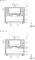
- Fig. 1 is an explanatory view illustrating a configuration of a gas supply apparatus according to Embodiment 1 of the present invention.
- Fig. 1 an XYZ orthogonal coordinate system is illustrated.
- the gas supply apparatus includes: a mounting table 19 (mounting portion) for mounting a wafer 25 which is a substrate to be processed; and a gas ejector 1 which is provided above the mounting table 19 and supplies gas from a low-vacuum processing chamber 18 (processing chamber) having an opening on a bottom surface to the wafer 25 below.
- a mounting table 19 mounting portion
- a gas ejector 1 which is provided above the mounting table 19 and supplies gas from a low-vacuum processing chamber 18 (processing chamber) having an opening on a bottom surface to the wafer 25 below.
- the gas ejector 1 has, as main components, a primary accommodating chamber 11, a gas supply port 12, a first-stage restricting cylinder 13 (first restricting cylinder), a second-stage restricting cylinder 14 (second restricting cylinder), and the low-vacuum processing chamber 18 (processing chamber).
- a nozzle portion 10 is formed of a configuration including a group of the restricting cylinders 13 and 14. That is, the nozzle portion 10 is provided between the primary accommodating chamber 11 and the low-vacuum processing chamber 18.
- the opening of the first-stage restricting cylinder 13 constituting the nozzle portion 10 has a circular cross-sectional shape with a diameter r1 (first diameter) on XY plane (in plan view).
- the first-stage restricting cylinder 13 supplies a source gas G1 in the primary accommodating chamber 11 downward (in a -Z direction).
- the diameter r1 is set such that pressure difference between the primary accommodating chamber 11 and the low-vacuum processing chamber 18 is greater than or equal to a predetermined pressure ratio.
- the second-stage restricting cylinder 14 is continuously formed with the first-stage restricting cylinder 13 along a Z direction.
- the opening of the bottom surface of the second-stage restricting cylinder 14 has a circular cross-sectional shape with a diameter r2 (second diameter) on XY plane (in plan view).
- the second-stage restricting cylinder 14 supplies the source gas G1 supplied from the first-stage restricting cylinder 13 to the low-vacuum processing chamber 18 below.
- the diameter r2 is set so as to satisfy "r2 > r1".
- the diameter r1 of the first-stage restricting cylinder 13 is 1.35 mm in diameter
- the depth (formation length extending in the Z direction) of the first-stage restricting cylinder 13 is 1 mm
- the diameter r2 of the second-stage restricting cylinder 14 is 8 mm in diameter
- the depth (formation length extending in the Z direction) of the second-stage restricting cylinder 14 is 4 mm.
- nitrogen gas is supplied as the source gas G1 at a flow rate of 4 slm (standard liter per minute). Therefore, the source gas G1 that has passed through the first-stage restricting cylinder 13 becomes an ultra-high-speed gas and is supplied into the low-vacuum processing chamber 18 via the second-stage restricting cylinder 14.
- the primary accommodating chamber 11 temporarily accommodates the source gas G1 supplied from the gas supply port 12.
- the pressure in the primary accommodating chamber 11 is a primary pressure.
- the source gas G1 supplied from the gas supply port 12 passes through the primary accommodating chamber 11, a secondary pressure is determined by the first-stage restricting cylinder 13.
- the source gas G1 is supplied into the low-vacuum processing chamber 18 via the second-stage restricting cylinder 14.
- a pressure ratio PC between the primary pressure in the primary accommodating chamber 11 and the secondary pressure in the low-vacuum processing chamber 18 is set to greater than or equal to 30 times. Then, the flow velocity of the source gas G1 that has passed through the first-stage restricting cylinder 13 becomes a flow velocity greater than or equal to Mach due to the pressure ratio PC. Due to the existence of the second-stage restricting cylinder 14, a phenomenon in which a Mach disk condition generated by a high-speed jet of the source gas G1 occurs is suppressed. Then, the source gas G1 is supplied into the low-vacuum processing chamber 18.
- the maximum Mach number of the source gas G1 as the ultra-high-speed gas exceeds "5" and is supplied to the wafer 25 on the mounting table 19.
- the gas supply apparatus can supply the gas to the wafer at a higher speed than a conventional gas supply apparatus.
- the second-stage restricting cylinder 14 pressure distribution and flow-velocity distribution in the low-vacuum processing chamber 18 can be relaxed to avoid an occurrence of a Mach disk MD condition, and the source gas G1 is supplied into the low-vacuum processing chamber 18 and is supplied to the wafer 25 placed on the mounting table 19 (wafer table). After the gas has been reacted, the gas is exhausted from an exhaust port 21 provided between the gas ejector 1 and the mounting table 19.
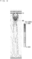
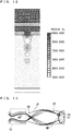
- Fig. 7 is an explanatory view schematically illustrating a speed condition of a gas jet using the gas supply apparatus according to Embodiment 1 having the nozzle portion 10.
- Fig. 8 is an explanatory view schematically illustrating a pressure condition of the gas jet using the gas supply apparatus according to Embodiment 1 having the nozzle portion 10.
- Fig. 9 is an explanatory view schematically illustrating a speed condition of a gas jet using a conventional gas supply apparatus having a nozzle portion configured only of a first-stage restricting cylinder 13.
- Fig. 10 is an explanatory view schematically illustrating a pressure condition of the gas jet using the conventional gas supply apparatus having the nozzle portion configured only of the first-stage restricting cylinder 13.
- the uppermost hatched portion corresponds to, for example, a formation region of an upper electrode 22 in Embodiment 4 to be described later.
- the uppermost hatched portion corresponds to the formation region of the upper electrode 22 in Embodiment 4 to be described later.
- the above-described pressure ratio PC of the primary pressure to the secondary pressure is set to greater than or equal to 30 times.
- the gas supply apparatus according to Embodiment 1 can supply the source gas G1 to the wafer 25 without extremely lowering the speed of the source gas G1.
- a Mach disk MD is generated in the conventional gas supply apparatus.
- Fig. 11 is an explanatory view schematically illustrating a speed condition of a gas jet in a case where the pressure ratio PC of the primary accommodating chamber 11 to the low-vacuum processing chamber 18 is less than 30 times in the configuration according to Embodiment 1.
- Fig. 12 is an explanatory view schematically illustrating a pressure condition of the gas jet in the case where the pressure ratio PC of the primary accommodating chamber 11 to the low-vacuum processing chamber 18 is less than 30 times in the configuration in Embodiment 1.
- the uppermost hatched portion corresponds to the formation region of the upper electrode 22 in Embodiment 4 to be described later.
- the above-described pressure ratio PC of the primary pressure to the secondary pressure is set to less than 30 times.
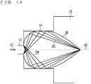
- Fig. 13 is an explanatory view schematically illustrating a Mach disk generation structure in a case of using the conventional gas supply apparatus having the nozzle portion configured only of the first-stage restricting cylinder 13.
- the primary pressure of the primary accommodating chamber 11 is higher than the secondary pressure of the low-vacuum processing chamber 18, that is, ejection pressure of the source gas G1 from the first-stage restricting cylinder 13 is higher than the pressure in the low-vacuum processing chamber 18, a flow having passed through an outlet (orifice outlet) of the first-stage restricting cylinder 13 causes a phenomenon called a shock cell structure (shock cell), and the above shock cell structures are periodically observed in a downstream direction.
- the shock cell structure means a structure of a shock wave in which reflected shock waves RS to be described later are repeatedly obtained at boundary regions JB (Jet Boundary) to be described below.
- the gas has not yet fully expanded. Therefore, expansion waves EW are generated at an edge of the orifice outlet, and the gas greatly expands to the outside.
- the expansion waves EW are reflected by the boundary region JB (Jet Boundary), become compression waves and return to a jet center axis side.
- the compression wave is a wave whose pressure is higher than a reference value. When the compression wave passes through, the pressure at the point where the compression wave passes rises.
- the expansion wave means a wave whose pressure is lower than a reference value. When the expansion wave passes through, the pressure at the point where the expansion wave passes lowers.
- barrel shock waves BS barrel shock waves
- a disk-shaped normal shock wave called a Mach disk MD (Mach shock wave) is formed.
- the flow behind the Mach disk MD is a subsonic flow.
- a reflected shock wave RS Reflect Shock is generated from an end of the barrel shock wave BS.
- a triple point TP is a point at which the barrel shock wave BS which is a compression wave, the Mach disk MD, and the reflected shock wave RS intersect.
- the first-stage restricting cylinder 13 provided in the nozzle portion 10 and having the opening with the diameter r1 can give directivity to the source gas G1 to be ejected to the low-vacuum processing chamber 18.
- the gas can be supplied to the wafer 25 which is the substrate to be processed at an ultra-high speed exceeding Mach.
- the gas supply apparatus has effects of being able to supply the source gas G1 suitable for formation of a film having a three-dimensional structure obtained by forming a film on a surface of the wafer 25 with high aspect ratio.
- a reactive gas is supplied as the source gas G1 to the wafer 25.
- the gas supply apparatus can supply the source gas G1 in a high-speed state to the wafer 25 which is a substrate to be processed, by setting the pressure ratio PC of the primary pressure in the primary accommodating chamber 11 to the secondary pressure in the low-vacuum processing chamber 18 to greater than or equal to 30 times.
- the gas supply apparatus according to Embodiment 1 can more effectively suppress a Mach disk MD, by setting the diameter r2 of the second-stage restricting cylinder 14 to be within 30 mm in diameter.
- a gas contact region which is a region to be brought into contact with the source gas G1, is formed to include quartz or an alumina material as a constituent material.
- a reactive gas is generally used as the source gas G1. Therefore, in the gas ejector 1 according to Embodiment 1 adopting the first aspect, at least the above gas contact region is formed of quartz or an alumina material. Since a quartz material surface and an alumina surface are chemically stable to the above-described reactive gas, it is possible to supply the reactive gas into the low-vacuum processing chamber 18 in a state where there is little chemical reaction between the reactive gas and the gas contact region in contact with the reactive gas.
- the gas ejector 1 is heated to 100°C or higher when the source gas G1 is supplied to the wafer 25, and the heated source gas G1 is supplied to the wafer 25.
- a configuration such as providing a heating processing mechanism such as a hot plate or the like near the gas ejector 1 is considered in order to perform heating processing.
- the reactive gas used as the source gas G1 is subjected to heating processing and receives thermal energy. Therefore, the gas supply apparatus adopting the second aspect can supply a more highly reactive gas to the low-vacuum processing chamber 18, has an effect of forming a film on the wafer 25 at a higher speed, and has an effect of being able to perform a high-speed film formation process.
- the source gas G1 supplied from the gas supply port 12 is a gas containing at least nitrogen, oxygen, fluorine, and hydrogen.
- the source gas G1 supplied from the gas supply port 12 is a gas containing at least nitrogen, oxygen, fluorine, and hydrogen gas. Therefore, the gas supply apparatus adopting the third aspect can be used not only for formation of an insulating film such as a nitride film or an oxide film, but also for resist peeling and surface treatment of the wafer 25 with high aspect ratio using an activated gas of a fluorinated gas serving as an etching gas or a cleaning gas. Furthermore, by applying an ultra-high-speed gas such as a hydrogen radical gas to the surface of the wafer 25, the source gas G1 usable for applications other than insulating film formation, an etching process, and a cleaning function can also be supplied. Therefore, the gas supply apparatus can be used for various film formation processes.
- an ultra-high-speed gas such as a hydrogen radical gas
- a fourth aspect where the source gas G1 supplied from the gas supply port 12 is a precursor gas may be adopted.
- the source gas G1 can be used as a reactive gas for surface treatment of the wafer 25 with high aspect ratio.
- the precursor gas to be a material of a deposited metal in film formation, the precursor gas necessary for film formation on the surface of the wafer 25, can be also supplied to the surface of the wafer 25 to perform film formation.
- a flow rate control unit that controls the gas flow rate of the source gas G1 supplied from the gas supply port 12 is provided such that the pressure is set to a pressure lower than or equal to the atmospheric pressure (1013.25 hPa) in the low-vacuum processing chamber 18 and higher than or equal to 10 kPa.
- a configuration in which a gas flow rate control device mass flow controller; MFC is provided in a supply path between a supply unit of the source gas G1 and the gas supply port 12 of the source gas G1, and the gas flow rate control device is controlled is considered as the flow rate control unit.
- the gas supply apparatus adopting the fifth aspect can improve stability of the flow velocity of the ultra-high-speed gas in the source gas G1 ejected from the nozzle portion 10 of the gas ejector 1 into the low-vacuum processing chamber 18, and can exhibit the effect of improving film forming quality, such as uniformization of the thickness or the like of the film formed on the surface of the wafer 25.
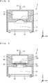
- Fig. 2 is an explanatory view illustrating a configuration of a gas supply apparatus according to Embodiment 2 of the present invention.
- Fig. 2 an XYZ orthogonal coordinate system is illustrated.
- the gas supply apparatus includes: a mounting table 19 (mounting portion) for mounting a wafer 25 which is a substrate to be processed; and a gas ejector 2 which is provided above the mounting table 19 and supplies gas from a low-vacuum processing chamber 18 having an opening to the wafer 25.
- the gas ejector 2 includes a primary accommodating chamber 11, a gas supply port 12, a first-stage restricting cylinder 13 (first restricting cylinder), a second-stage restricting cylinder 14 (second restricting cylinder), a third-stage restricting cylinder 15 (third restricting cylinder), and the low-vacuum processing chamber 18 as main components.
- a nozzle portion 20 is formed of a configuration including a group of the restricting cylinders 13 to 15. That is, the nozzle portion 20 is provided between the primary accommodating chamber 11 and the low-vacuum processing chamber 18.
- the opening of the first-stage restricting cylinder 13 constituting the nozzle portion 20 has a circular cross-sectional shape with a diameter r1 in plan view, and supplies a source gas G1 in the primary accommodating chamber 11 downward.
- the second-stage restricting cylinder 14 is continuously formed with the first-stage restricting cylinder 13 along a Z direction.
- the opening of the bottom surface of the second-stage restricting cylinder 14 has a circular cross-sectional shape with a diameter r2 in plan view, and supplies the source gas G1 supplied from the first-stage restricting cylinder 13 downward.
- the third-stage restricting cylinder 15 is continuously formed with the second-stage restricting cylinder 14 along the Z direction.
- the opening of the bottom surface of the third-stage restricting cylinder 15 has a circular cross-sectional shape with a diameter r3 (third diameter) on XY plane (in plan view).
- the third-stage restricting cylinder 15 supplies the source gas G1 supplied from the second-stage restricting cylinder 14 to the low-vacuum processing chamber 18 below.
- the diameter r3 is set so as to satisfy "r3 > r2".
- the diameter r1 of the first-stage restricting cylinder 13 is 1.35 mm in diameter
- the depth of the first-stage restricting cylinder 13 is 1 mm
- the diameter r2 of the second-stage restricting cylinder 14 is 8 mm and the depth of the second-stage restricting cylinder 14 is 4 mm
- the diameter r3 of the third-stage restricting cylinder 15 is set to 20 mm in diameter
- the depth (formation length extending in the Z direction) of the third-stage restricting cylinder 15 is set to 46 mm
- a nitrogen gas for example, is supplied at a flow rate of 4 slm. Then, the source gas G1 passed through the first-stage restricting cylinder 13 becomes an ultra-high-speed gas and is supplied into the low-vacuum processing chamber 18 via the second-stage restricting cylinder 14 and the third-stage restricting cylinder 15.
- the nozzle portion 20 is configured of the first-stage restricting cylinder 13, the second-stage restricting cylinder 14, and the third-stage restricting cylinder 15 having the openings with the diameter r1, the diameter r2, and the diameter r3, respectively. Therefore, it is possible to give directivity to the source gas G1 ejected into the low-vacuum processing chamber 18. In this case, similarly to Embodiment 1, existence of the second-stage restricting cylinder 14 can effectively suppress a Mach disk MD phenomenon.
- the gas supply apparatus according to the Embodiment 2 has effects similar to those of the gas supply apparatus according to Embodiment 1, and also has the effects in the case of adopting the first to fifth aspects.
- the gas ejector 2 according to Embodiment 2 further includes the third-stage restricting cylinder 15 as the nozzle portion 20, and the diameter r3 of the third-stage restricting cylinder 15 is set to be longer than the diameter r2 of the second-stage restricting cylinder 14. Therefore, it is possible to supply the source gas G1 to the wafer 25 in a state where the occurrence of Mach disk MD caused by the high-speed jet generated at the pressure ratio PC is suppressed more than in the case of Embodiment 1.
- Fig. 3 is an explanatory view illustrating a configuration of a gas supply apparatus according to Embodiment 3 of the present invention.
- Fig. 3 an XYZ orthogonal coordinate system is illustrated.
- the gas supply apparatus includes: a mounting table 19 (mounting portion) for mounting a wafer 25 which is a substrate to be processed; and a gas ejector 3 which is provided above the mounting table 19 and supplies gas from a low-vacuum processing chamber 18 having an opening to the wafer 25.
- the gas ejector 3 includes a primary accommodating chamber 11, a gas supply port 12, a first-stage restricting cylinder 13 (first restricting cylinder), a hemispherical restricting cylinder 17 (second restricting cylinder), and the low-vacuum processing chamber 18 as main components.
- a nozzle portion 30 is formed of a configuration including a group of the two restricting cylinders 13 and 17. That is, the nozzle portion 30 is provided between the primary accommodating chamber 11 and the low-vacuum processing chamber 18.
- the opening of the first-stage restricting cylinder 13 (first restricting cylinder) constituting the nozzle portion 30 has a circular cross-sectional shape with a diameter r1, and supplies a source gas G1 in the primary accommodating chamber 11 downward.
- the hemispherical restricting cylinder 17 is continuously formed with the first-stage restricting cylinder 13 along a Z direction.
- the opening of the bottom surface of the hemispherical restricting cylinder 17 has a circular cross-sectional shape with a diameter r2b (second diameter) on XY plane.
- the hemispherical restricting cylinder 17 supplies the source gas G1 supplied from the first-stage restricting cylinder 13 to the low-vacuum processing chamber 18 below.
- the diameter r2b of the bottom surface is set so as to satisfy "r2b > r1".
- the nozzle portion 30 is configured of the first-stage restricting cylinder 13 and the hemispherical restricting cylinder 17 having the openings with the diameter r1 and the diameters r2 (r2t to r2b), respectively. Therefore, it is possible to give directivity to the source gas G1 ejected into the low-vacuum processing chamber 18. In this case, similarly to Embodiment 1, existence of the hemispherical restricting cylinder 17 has the effect of suppressing a Mach disk MD phenomenon.
- the gas supply apparatus according to the Embodiment 3 has effects similar to those of the gas supply apparatus according to Embodiment 1, and also has the effects in the case of adopting the first to fifth aspects.
- the hemispherical restricting cylinder 17 (second restricting cylinder) in the gas ejector 3 according to Embodiment 3 is formed into a hemispherical shape such that the diameter r2 of the opening becomes longer as it approaches the low-vacuum processing chamber 18 (in the -Z direction). Therefore, it is possible to supply the source gas G1 to the wafer 25 in a state where the occurrence of Mach disk MD caused by the high-speed jet generated at the pressure ratio PC is suppressed more than in the case of Embodiment 1.
- a third-stage restricting cylinder may be further provided under the hemispherical restricting cylinder 17, similarly to the third-stage restricting cylinder 15 according to Embodiment 2.
- a columnar shape having a diameter identical to the diameter r2b of the bottom surface of the hemispherical restricting cylinder 17 or the like is considered.
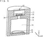
- Figs. 4 and 5 are explanatory views illustrating a configuration of a gas supply apparatus according to Embodiment 4 of the present invention.
- Fig. 4 is a cross-sectional view
- Fig. 5 is a perspective view.
- an XYZ orthogonal coordinate system is illustrated.
- the gas supply apparatus includes a mounting table 19 (mounting portion) for mounting a wafer 25 which is a substrate to be processed; and a gas ejector 4 which is provided above the mounting table 19 and supplies gas from a low-vacuum processing chamber 18 having an opening to the wafer 25.
- the gas ejector 4 has a primary accommodating chamber 11, a gas supply port 12, a first-stage restricting cylinder 13X (first restricting cylinder), a second-stage restricting cylinder 14X (second restricting cylinder), an upper electrode 22, a lower electrode 24, and the low-vacuum processing chamber 18 as main components.
- a nozzle portion 40 is formed of a configuration including a group of the two restricting cylinders 13X and 14X, and the lower electrode 24. That is, the nozzle portion 40 is provided between the primary accommodating chamber 11 and the low-vacuum processing chamber 18.
- the upper electrode 22 and the lower electrode 24 each having a dielectric such as alumina on surfaces facing each other are circular on XY plane (in plan view) and are provided so as to face each other. Note that a configuration may be possible in which a dielectric is provided only on one of the surfaces of the upper electrode 22 and the lower electrode 24, the surfaces facing each other.
- the gas ejector 4 has the upper electrode 22 and the lower electrode 24 (first and second electrodes) provided so as to face each other.
- a discharge space is formed between the upper electrode 22 and the lower electrode 24.
- At least one of the upper electrode 22 and the lower electrode 24 has a dielectric on the surface forming the discharge space.
- the upper electrode 22 is disposed near the bottom surface in the primary accommodating chamber 11.
- the lower electrode 24 is arranged under the bottom surface of the primary accommodating chamber 11 so as to form part of the bottom surface of the primary accommodating chamber 11.
- a through hole provided at the center of the lower electrode 24 serves as the first-stage restricting cylinder 13X.
- the opening of the first-stage restricting cylinder 13X (first restricting cylinder) constituting the nozzle portion 40 has a circular cross-sectional shape with a diameter r1 (first diameter) on XY plane (in plan view), and supplies a source gas G1 in the primary accommodating chamber 11 downward.
- the second-stage restricting cylinder 14X is continuously formed just under the lower electrode 24 including the first-stage restricting cylinder 13X along a Z direction.
- the opening of the second-stage restricting cylinder 14X has a circular cross-sectional shape with a diameter r2 (second diameter) on XY plane (in plan view), and supplies the source gas G1 supplied from the first-stage restricting cylinder 13 to the low-vacuum processing chamber 18 below.
- the diameter r2 is set so as to satisfy "r2 > r1".
- the gas ejector 4 has a gas ionization unit inside.
- the gas ionization unit ionizes the source gas G1 to obtain an ionized or radicalized gas in the discharge space between the upper electrode 22 and the lower electrode 24 facing each other with the dielectric interposed therebetween.
- the gas ionization unit has a discharge space between the upper electrode 22 and the lower electrode 24 facing each other with the dielectric interposed therebetween.
- the gas ionization unit can apply an alternating voltage between the upper electrode 22 and the lower electrode 24, generate dielectric-barrier discharge in the discharge space, and supply an ionized gas or a radicalized gas obtained by ionizing or radicalizing the source gas G1 into the low-vacuum processing chamber 18 via the second-stage restricting cylinder 14X.
- the gas ejector 4 is characterized by including the gas ionization unit which is provided near a boundary region between the primary accommodating chamber 11 and the nozzle portion 40, and produces an ionized gas or a radicalized gas which is an ionized or radicalized source gas G1 obtained by ionizing the source gas G1 supplied from the gas supply port 12.
- the nozzle portion 40 is configured of the first-stage restricting cylinder 13X and the second-stage restricting cylinder 14X having the openings with the diameter r1 and the diameter r2, respectively. Therefore, it is possible to give directivity to the source gas G1 ejected into the low-vacuum processing chamber 18. In this case, similarly to Embodiment 1, existence of the second-stage restricting cylinder 14X has the effect of capable of suppressing a Mach disk MD phenomenon.
- the gas supply apparatus according to the Embodiment 4 has effects similar to those of the gas supply apparatus according to Embodiment 1, and also has the effects in the case of adopting the first to fifth aspects.
- heating processing according to the second aspect of Embodiment 4 a discharge process between the upper electrode 22 and the lower electrode 24 can be utilized.
- the gas ejector 4 according to Embodiment 4 can cause the above gas ionization unit to perform gas discharge in the gas ejector 4, and can directly apply an ionized gas or a radicalized gas which is a directional ultra-high-speed jet gas to the surface of the wafer 25 from the low-vacuum processing chamber 18. Therefore, as compared with the plasma CVD/ALD apparatus which is a conventional film forming apparatus, the gas ejector 4 according to Embodiment 4 can apply an activated ionized gas or an activated radicalized gas having higher density and a higher electric field to the surface of the wafer 25, and realize a higher-quality film formation process.
- the gas ejector 4 has effects of easily forming a film on the wafer 25 with high aspect ratio and a film having a three-dimensional structure.
- the above gas ionization unit has the discharge space between the upper electrode 22 and the lower electrode 24 facing each other with the dielectric interposed therebetween.
- An alternating voltage is applied between the upper electrode 22 and the lower electrode 24, dielectric-barrier discharge is generated in the discharge space, and an ionized gas or a radicalized gas obtained by ionizing or radicalizing the source gas G1 can be supplied.
- a dielectric-barrier discharge mechanism (the upper electrode 22 and the lower electrode 24) is provided in the gas ejector 4. Therefore, it is possible to achieve an effect of enabling a high-quality film formation process by using the supplied ionized gas or radicalized gas.
- the first-stage restricting cylinder 13X is configured as the through hole formed in the lower electrode 24 (second electrode), and the discharge gas is ejected into the low-vacuum processing chamber 18. Therefore, it is possible to apply the ionized gas or the radicalized gas generated by the dielectric-barrier discharge to the surface of the wafer 25 in an extremely short time of a millisecond or less. Therefore, the gas supply apparatus according to Embodied form 4 can apply even the ionized gas or the radicalized gas which is generated by the discharge and has a very short lifetime, to the surface of the wafer 25 while suppressing attenuation to the minimum. Therefore, the gas supply apparatus has effects of enabling film formation at a low temperature and increasing film formation speed.
- Embodiment 4 describes a case where the shape of each of the upper electrode 22 and the lower electrode 24 in plan view is circular; however, it is a matter of course that the shape is not limited to this shape.
- Fig. 6 is an explanatory view illustrating a configuration of a gas supply apparatus according to Embodiment 5 of the present invention.
- Fig. 6 an XYZ orthogonal coordinate system is illustrated.
- the gas supply apparatus includes: a mounting table 19 (mounting portion) for mounting a wafer 25 which is a substrate to be processed; and a gas ejector 100 which is provided above the mounting table 19 and supplies gas from a low-vacuum processing chamber 180 having an opening to the wafer 25.
- the gas ejector 100 includes a primary accommodating chamber 110, a gas supply port 12, first-stage restricting cylinders 13a to 13d (a plurality of first restricting cylinders), second-stage restricting cylinders 14a to 14d (a plurality of second restricting cylinders), and the low-vacuum processing chamber 180 as main components.
- Nozzle portions 10a to 10d are formed of configurations including the first-stage restricting cylinders 13a to 13d and the second-stage restricting cylinders 14a to 14d, respectively. That is, the nozzle portions 10a to 10d are provided between the primary accommodating chamber 110 and the low-vacuum processing chamber 180.
- the nozzle portion 10a is configured of the first-stage restricting cylinder 13a and the second-stage restricting cylinder 14a.
- the nozzle portion 10b is configured of the first-stage restricting cylinder 13b and the second-stage restricting cylinder 14b.
- the nozzle portion 10c is configured of the first-stage restricting cylinder 13c and the second-stage restricting cylinder 14c.
- the nozzle portion 10d is configured of the first-stage restricting cylinder 13d and the second-stage restricting cylinder 14d.
- each of the first-stage restricting cylinders 13a to 13d has a circular cross-sectional shape with a diameter r1 in plan view, and supplies a source gas G1 in the primary accommodating chamber 110 downward.
- the second-stage restricting cylinders 14a to 14d are continuously formed with the first-stage restricting cylinders 13a to 13d along a Z direction, respectively.
- the opening of each of the second-stage restricting cylinders 14a to 14d has a circular cross-sectional shape with a diameter r2 in plan view.
- the second-stage restricting cylinders 14a to 14d supply downward the source gas G1 supplied from the first-stage restricting cylinder 13a to 13d, respectively. After the gas has been reacted, the gas is exhausted from an exhaust port 210 provided between the gas ejector 100 and the mounting table 19.
- the nozzle portions 10a to 10d are configured of the first-stage restricting cylinders 13a to 13d and the second-stage restricting cylinders 14a to 14d having the diameter r1 and the diameter r2, respectively. Therefore, it is possible to give directivity to the source gas G1 ejected into the low-vacuum processing chamber 180. In this case, similarly to Embodiment 1, existence of the second-stage restricting cylinders 14a to 14d provides an effect of effectively suppressing a Mach disk MD phenomenon.
- the gas supply apparatus according to the Embodiment 5 has effects similar to those of the gas supply apparatus according to Embodiment 1, and also has the effects in the case of adopting the first to fifth aspects.
- the gas ejector 100 according to Embodiment 5 can uniformly apply high-speed gas having directivity from the nozzle portions 10a to 10d (the plurality of nozzle portions) to the entire surface of the wafer 25, and can perform a high-quality and uniform film formation process in a relatively short time even upon film formation on the wafer 25 with high aspect ratio and upon three-dimensional film formation on the surface of the wafer 25 having a three-dimensional structure.
- a sixth aspect may be adopted in which when the diameters r1 of the first-stage restricting cylinders 13a to 13d are set to diameters r1a to r1d, the diameters r1a to r1d are set to different values. That is, the sixth aspect may be adopted in which the diameters r1 of the nozzle portions 10a to 10d differ from one another.
- flow rates and speeds of gas ejected from the nozzle portions 10a to 10d are controlled such that the flow rates and the speeds differ from one another. Therefore, for example, if the gas amounts of the source gas G1 containing an ionized gas, a radicalized gas, or the like ejected from the nozzle portions 10a to 10d are independently controlled correspondingly to the locations on the surface of the wafer 25 where the gas hits, an effect is provided that leads to an improvement in film formation quality such as uniform film formation on the entire surface of the wafer 25.
- a seventh aspect may be adopted in which the structure of each of the nozzle portions 10a to 10d is similar to that of the nozzle portion 40 according to Embodiment 4, and a plurality of gas ionization units provided correspondingly to the nozzle portions 10a to 10d can be controlled independently.
- the plurality of gas ionization units provided correspondingly to the nozzle portions 10a to 10d can be controlled independently. Therefore, by controlling the plurality of ejected gas amounts of the ionized gas or the radicalized gas and discharge power, the gas amount of the ionized gas or the radicalized gas to be ejected and the discharge power can be controlled correspondingly to the location on the surface of the wafer 25 where the gas hits.
- the seventh aspect in the gas supply apparatus according to Embodiment 5 provides an effect that leads to an improvement in film formation quality such as uniform film formation on the entire surface of the wafer 25.
- Embodiment 5 the structure similar to that of the nozzle portion 10 according to Embodiment 1 is adopted as the structure of each of the nozzle portions 10a to 10d.
- a structure similar to that of the nozzle portion 20 according to Embodiment 2 the nozzle portion 30 according to Embodiment 3, or the nozzle portion 40 according to Embodiment 4 may be adopted.
- the diameters r1 of the first-stage restricting cylinders 13a to 13d are set to the diameters r1a to r1d
- the diameters r1a to r1d are set to values different from one another.
- the diameters r2 of the second-stage restricting cylinders 14a to 14d are set to diameters r2a to r2d
- the diameters r2a to r2d may be set to values different from one another (a first modification).
- each of the nozzle portions 10a to 10d according to Embodiment 5 further includes a third-stage restricting cylinder 15 (15a to 15d) as in Embodiment 2, when diameters r3 of the third-stage restricting cylinders 15a to 15d are set to diameters r3a to r3d, the diameters r3a to r3d may be set to values different from one another (a second modification).
- flow rates and speeds of gas ejected from the nozzle portions 10a to 10d are variably controlled such that the flow rates and the speeds differ from one another.
- the above-described first or second modification may be adopted and the diameters r2 (including the diameters of the third-stage restricting cylinders according to the modification) of the hemispherical restricting cylinders 17, the diameters r2 of the second-stage restricting cylinders 14X, or the like may be set to different values among the nozzle portions 10a to 10d.
- the maximal number of stages of restricting cylinders is three (Embodiment 2).
- a configuration of providing four or more stages of restricting cylinders is naturally considered, such as providing a fourth-stage restricting cylinder below the third-stage restricting cylinder 15 according to Embodiment 2.
Landscapes
- Chemical & Material Sciences (AREA)
- Engineering & Computer Science (AREA)
- Metallurgy (AREA)
- General Chemical & Material Sciences (AREA)
- Chemical Kinetics & Catalysis (AREA)
- Materials Engineering (AREA)
- Mechanical Engineering (AREA)
- Organic Chemistry (AREA)
- Plasma & Fusion (AREA)
- Physics & Mathematics (AREA)
- Analytical Chemistry (AREA)
- Electromagnetism (AREA)
- Chemical Vapour Deposition (AREA)
Abstract
Description
- The present invention relates to a gas supply apparatus for a film formation process.
- In the field of semiconductor manufacturing, processes such as a film formation process of forming an insulating film or the like on a substrate of an object to be processed such as a wafer, and etching, cleaning, and the like of a film surface formed by film formation are performed. These processes are required to be performed at high speed and with high-quality techniques. For example, together with various high-performance and excellent film formation processes including film formation of a highly insulating thin film, a semiconductor thin film, a high dielectric thin film, a light-emitting thin film, a highly magnetic thin film, a super-hard thin film, and the like, an etching process, peeling, and a cleaning process with high quality have been pursued. Realization of high-quality and uniform film formation on a surface of a wafer (surface of a substrate to be processed) having a large area and high processing speed are highly valued.
- The various thin-film techniques, and etching, peeling and cleaning processes described above have been applied not only to semiconductor elements but also to various fields of application.
- In particular, among them, in the thin-film formation technique, a basic technique of promoting nitriding, oxidation and hydrogen bonding by chemical reaction on a surface of a substance such as a metal or an insulator material is important in thin-film formation. Based on this basic technique, a thin film is subjected to various heat treatments and chemical-reaction processes, and thus high-quality thin-film formation is realized.
- Specifically, in the manufacture of a semiconductor device, there are film formation methods of high-function films such as a low-impedance highly conductive film functioning as circuit wiring in a semiconductor chip, a highly magnetic film having a wiring coil function or a magnet function of a circuit, a high dielectric film having a capacitor function of a circuit, and a highly insulating film having a high insulating function with a little electrical leakage current, the highly insulating film formed by oxidation or nitriding. In order to realize these film formation methods for high-function films, a thermal CVD (Chemical Vapor Deposition) apparatus, a photo-CVD apparatus, a plasma CVD apparatus, a thermal ALD (Atomic Layer Deposition) apparatus, or a plasma ALD apparatus is used. In particular, plasma CVD/ALD apparatuses are often used. For example, the plasma CVD/ALD apparatus is advantageous in that the plasma CVD/ALD apparatus has lower film-formation temperature and can perform a film formation process faster in a shorter time than a thermal/photo CVD/ALD apparatus.
- For example, in a case where a gate insulating film such as a nitride film (SiON, HfSiON or the like) or an oxide film (SiO2, HfO2) is formed on a wafer which is a substrate to be processed, the following technique using a plasma CVD/ALD apparatus is generally adopted.
- The thermal CVD/ALD apparatus heats the wafer and the inside of a container to increase reactivity of a supply gas to form a film on the wafer; however, if the wafer is exposed to a high temperature, thermal damage or the like leads to a decrease in yield.
- Therefore, nowadays, film formation with plasma CVD/ALD using plasma is often used in lieu of thermal CVD/ALD. (Plasma) CVD/ALD techniques are disclosed in, for example,
Patent Documents 1 to 3. - In a conventional film formation processing apparatus using plasma CVD/ALD, thermal CVD/ALD or the like as disclosed in
Patent Document 1, a method is adopted in which the film formation apparatus is filled with gas and the filled gas is activated by plasma energy or thermal energy, and a thin film is deposited by a chemical reaction process with the gas supplied to a surface of a wafer. The activated gas filled in the film formation processing apparatus only has a random gas flow velocity due to Brownian motion, and a gas particle itself does not have high speed. Therefore, the method is effective for a deposition film formation reaction on a surface of a substrate, but is not suitable for uniformly forming a film on an extremely uneven surface of a substrate and for uniformly forming a three-dimensional film surface. In addition, in the case of a highly reactive gas, since chemical reaction time is short, the lifetime is very short. Therefore, there is a disadvantage that reaction is promoted only on a surface of a substrate, a supply gas does not reach an extremely uneven surface with high aspect ratio, and uniform film formation cannot be performed. In this case, it is necessary to lead a reactant gas to the inside of a wafer in a short time so that film formation is performed by uniformly carrying out reaction even inside the wafer, or to give energy to gas filled inside the wafer to convert the gas into an activated gas. - In a CVD/ALD film formation processing apparatus disclosed in
Patent Document 2, gas is uniformly supplied into a container and deposited on entirety of a wafer. However, there is a problem that in a case where reactivity of the gas is high, the gas loses the reactivity before reaching the wafer. Therefore, there are known a method of generating plasma in a container to generate a highly reactive gas and supplying the gas to a substrate, and a method of increasing the temperature inside a container or a wafer to increase reactivity. - In a plasma CVD/ALD apparatus using plasma disclosed in
Patent Document 3, energy of plasma is given to gas being supplied, and the gas is converted into a highly reactive gas and supplied. In that case, there is an advantage that the temperature inside a wafer or a container can be set lower than the temperature in the case of thermal film formation; however, since a plasma generation source and a surface to be processed are required to be located close to each other, there is a disadvantage that the substrate itself, which is located close to the plasma generation source, is damaged due to an influence of plasma. In addition, when the conventional CVD/ALD film formation processing apparatus and the currently operating plasma CVD/ALD apparatus are compared with each other, the currently operating plasma CVD/ALD apparatus is suitable for a three-dimensional film formation process on a relatively less uneven surface of a wafer. However, it is substantially impossible to realize a three-dimensional film formation process on a more uneven surface of a wafer having higher aspect ratio and to obtain a high-quality three-dimensional film formation structure. - In a manufacturing method for manufacturing a three-dimensional-structure semiconductor disclosed in
Patent Document 4, it is necessary to form a uniform barrier film located around a TSV (through-silicon via) structure. In this case, there is limitation in uniform film formation in the depth direction. Therefore, the barrier film to be formed is divided into a plurality of layers in the depth direction, and several layers are formed each time. -
- Patent Document 1: Japanese Patent Application Laid-Open No.
2004-111739 - Patent Document 2: Japanese Patent Application Laid-Open No.
2013-219380 - Patent Document 3: Japanese Patent Application Laid-Open No.
2001-135628 - Patent Document 4: Japanese Patent Application Laid-Open No.
2014-86498 - As described above, in the conventional thin-film formation techniques, since the film formation process is performed by supplying a supply gas and setting the inside of the film formation processing apparatus at a predetermined pressure, it is not necessary to supply gas having directivity at high speed. Therefore, the conventional thin-film formation techniques are not suitable for a film formation process for an uneven surface, which has been recently demanded. The techniques are particularly not suitable for a film formation process for a wafer having high aspect ratio, a representative example of which is a wafer having a deep hole.
- In addition, a method is suitable for supplying a highly reactive gas to a surface of a wafer in a short time. In the method, a single restricting cylinder (orifice) is provided as means for quickly supplying gas to a low-vacuum processing chamber to increase gas supply speed, the gas is ejected in a low-vacuum environment in the low-vacuum processing chamber, and thus, the gas is ejected at an ultra-high speed exceeding Mach. In that case, it is necessary to set the pressure difference between the pressure in a gas supply apparatus and the pressure in the low-vacuum processing chamber in a low-vacuum state to be greater than or equal to a predetermined pressure ratio. As the pressure difference is greater or the pressure inside the low-vacuum processing chamber is lower, the gas is supplied at higher speed and the gas can be supplied on the surface of the wafer in a shorter time. If the diameter of the opening of a flow path in the restricting cylinder is reduced and the pressure difference is increased, flow velocity becomes faster and thus gas supply time becomes shorter.
- However, in a case of ejecting gas at an ultra-high speed exceeding Mach, the gas speed affects a gas flow velocity frame (gas jet speed) at the gas impact pressure and the temperature condition of Mach speed, and brings about an effect of extremely lowering the gas flow velocity at a certain ejection position. As a result, a phenomenon called a Mach disk condition (condition where the gas flow velocity is extremely lowered at a certain ejection position) occurs. It is preferable to minimize the phenomenon of this Mach disk condition; however, no specific solution has been found.
- The present invention solves the above-described problems. An object of the present invention is to provide a gas supply apparatus capable of effectively suppressing a phenomenon in which extreme deceleration of gas occurs in association with an impact pressure and a temperature condition generated by a gas supplied to a substrate at an ultra-high speed exceeding Mach when the gas is supplied to the substrate at the ultra-high speed.
- A gas supply apparatus according to the present invention includes: a mounting portion for mounting a substrate to be processed; and a gas ejector which is provided above the mounting portion and supplies gas from a processing chamber having an opening on a bottom surface to the substrate to be processed. The gas ejector includes: a primary accommodating chamber which temporarily accommodates gas supplied from a gas supply port; the processing chamber; and a nozzle portion which is provided between the primary accommodating chamber and the processing chamber. The nozzle portion has: a first restricting cylinder whose opening has a circular cross-sectional shape with a first diameter in plan view, and which supplies the gas in the primary accommodating chamber downward; and a second restricting cylinder whose opening has a circular cross-sectional shape with a second diameter in plan view, and which supplies the gas supplied from the first restricting cylinder to the processing chamber. The first diameter is set such that pressure difference between the primary accommodating chamber and the processing chamber is greater than or equal to a predetermined pressure ratio. The second diameter is set to be longer than the first diameter.
- In the gas ejector of the gas supply apparatus of the present invention according to
claim 1, the first restricting cylinder having the first diameter in the nozzle portion can give directivity to gas to be ejected to the processing chamber. Thus, gas can be supplied to the substrate to be processed at an ultra-high speed exceeding Mach. In this case, due to existence of the second restricting cylinder provided between the first restricting cylinder and the processing chamber, it is possible to suppress a Mach disk phenomenon in which ejected gas is extremely decelerated by the impact pressure and the temperature condition generated by the gas ejecting at an ultra-high speed. - As a result, the gas supply apparatus of the present invention according to
claim 1 has the effect of being able to supply gas suitable for film formation on a surface of a wafer with high aspect ratio to a substrate to be processed. - The objects, features, aspects, and advantages of the present invention will become more apparent from the following detailed description and the accompanying drawings.
-
-
Fig. 1 is an explanatory view illustrating a configuration of a gas supply apparatus according toEmbodiment 1 of the present invention. -
Fig. 2 is an explanatory view illustrating a configuration of a gas supply apparatus according toEmbodiment 2 of the present invention. -
Fig. 3 is an explanatory view illustrating a configuration of a gas supply apparatus according toEmbodiment 3 of the present invention. -
Fig. 4 is an explanatory view (part 1) illustrating a configuration of a gas supply apparatus according toEmbodiment 4 of the present invention. -
Fig. 5 is an explanatory view (part 2) illustrating the configuration of the gas supply apparatus according toEmbodiment 4 of the present invention. -
Fig. 6 is an explanatory view illustrating a configuration of a gas supply apparatus according toEmbodiment 5 of the present invention. -
Fig. 7 is an explanatory view schematically illustrating a speed condition of a gas jet using the gas supply apparatus according toEmbodiment 1. -
Fig. 8 is an explanatory view schematically illustrating a pressure condition of a gas jet using the gas supply apparatus according toEmbodiment 1. -
Fig. 9 is an explanatory view schematically illustrating a speed condition of a gas jet using a conventional gas supply apparatus. -
Fig. 10 is an explanatory view schematically illustrating a pressure condition of the gas jet using the conventional gas supply apparatus. -
Fig. 11 is an explanatory view schematically illustrating a speed condition of a gas jet in a case where the pressure ratio of a primary accommodating chamber to a low-vacuum processing chamber is less than 30 times. -
Fig. 12 is an explanatory view schematically illustrating a pressure condition of the gas jet in a case where the pressure ratio of the primary accommodating chamber to the low-vacuum processing chamber is less than 30 times. -
Fig. 13 is an explanatory view schematically illustrating a Mach disk generation structure in the case of using the conventional gas supply apparatus. -
Fig. 14 is an explanatory view schematically illustrating effects in the case of using the gas supply apparatus according to the present embodiment. -
Fig. 1 is an explanatory view illustrating a configuration of a gas supply apparatus according toEmbodiment 1 of the present invention. InFig. 1 , an XYZ orthogonal coordinate system is illustrated. - As illustrated in
Fig. 1 , the gas supply apparatus according toEmbodiment 1 includes: a mounting table 19 (mounting portion) for mounting awafer 25 which is a substrate to be processed; and agas ejector 1 which is provided above the mounting table 19 and supplies gas from a low-vacuum processing chamber 18 (processing chamber) having an opening on a bottom surface to thewafer 25 below. - The
gas ejector 1 has, as main components, a primaryaccommodating chamber 11, agas supply port 12, a first-stage restricting cylinder 13 (first restricting cylinder), a second-stage restricting cylinder 14 (second restricting cylinder), and the low-vacuum processing chamber 18 (processing chamber). - A
nozzle portion 10 is formed of a configuration including a group of the restrictingcylinders nozzle portion 10 is provided between the primaryaccommodating chamber 11 and the low-vacuum processing chamber 18. - The opening of the first-
stage restricting cylinder 13 constituting thenozzle portion 10 has a circular cross-sectional shape with a diameter r1 (first diameter) on XY plane (in plan view). The first-stage restricting cylinder 13 supplies a source gas G1 in the primaryaccommodating chamber 11 downward (in a -Z direction). The diameter r1 is set such that pressure difference between the primaryaccommodating chamber 11 and the low-vacuum processing chamber 18 is greater than or equal to a predetermined pressure ratio. - The second-
stage restricting cylinder 14 is continuously formed with the first-stage restricting cylinder 13 along a Z direction. The opening of the bottom surface of the second-stage restricting cylinder 14 has a circular cross-sectional shape with a diameter r2 (second diameter) on XY plane (in plan view). The second-stage restricting cylinder 14 supplies the source gas G1 supplied from the first-stage restricting cylinder 13 to the low-vacuum processing chamber 18 below. The diameter r2 is set so as to satisfy "r2 > r1". - For example, the diameter r1 of the first-
stage restricting cylinder 13 is 1.35 mm in diameter, the depth (formation length extending in the Z direction) of the first-stage restricting cylinder 13 is 1 mm, the diameter r2 of the second-stage restricting cylinder 14 is 8 mm in diameter, and the depth (formation length extending in the Z direction) of the second-stage restricting cylinder 14 is 4 mm. For example, nitrogen gas is supplied as the source gas G1 at a flow rate of 4 slm (standard liter per minute). Therefore, the source gas G1 that has passed through the first-stage restricting cylinder 13 becomes an ultra-high-speed gas and is supplied into the low-vacuum processing chamber 18 via the second-stage restricting cylinder 14. - The primary
accommodating chamber 11 temporarily accommodates the source gas G1 supplied from thegas supply port 12. The pressure in the primaryaccommodating chamber 11 is a primary pressure. - After the source gas G1 supplied from the
gas supply port 12 passes through the primaryaccommodating chamber 11, a secondary pressure is determined by the first-stage restricting cylinder 13. The source gas G1 is supplied into the low-vacuum processing chamber 18 via the second-stage restricting cylinder 14. - At that time, a pressure ratio PC between the primary pressure in the primary
accommodating chamber 11 and the secondary pressure in the low-vacuum processing chamber 18 is set to greater than or equal to 30 times. Then, the flow velocity of the source gas G1 that has passed through the first-stage restricting cylinder 13 becomes a flow velocity greater than or equal to Mach due to the pressure ratio PC. Due to the existence of the second-stage restricting cylinder 14, a phenomenon in which a Mach disk condition generated by a high-speed jet of the source gas G1 occurs is suppressed. Then, the source gas G1 is supplied into the low-vacuum processing chamber 18. - For example, if the primary pressure in the primary
accommodating chamber 11 is 30 kPa and the pressure in the low-vacuum processing chamber 18 is 266 Pa, the maximum Mach number of the source gas G1 as the ultra-high-speed gas exceeds "5" and is supplied to thewafer 25 on the mounting table 19. - At this time, since the Mach disk condition which is likely to occur is effectively suppressed by the existence of the second-
stage restricting cylinder 14, the gas supply apparatus can supply the gas to the wafer at a higher speed than a conventional gas supply apparatus. - That is, due to provision of the second-
stage restricting cylinder 14, pressure distribution and flow-velocity distribution in the low-vacuum processing chamber 18 can be relaxed to avoid an occurrence of a Mach disk MD condition, and the source gas G1 is supplied into the low-vacuum processing chamber 18 and is supplied to thewafer 25 placed on the mounting table 19 (wafer table). After the gas has been reacted, the gas is exhausted from anexhaust port 21 provided between thegas ejector 1 and the mounting table 19. -
Fig. 7 is an explanatory view schematically illustrating a speed condition of a gas jet using the gas supply apparatus according toEmbodiment 1 having thenozzle portion 10. -
Fig. 8 is an explanatory view schematically illustrating a pressure condition of the gas jet using the gas supply apparatus according toEmbodiment 1 having thenozzle portion 10. -
Fig. 9 is an explanatory view schematically illustrating a speed condition of a gas jet using a conventional gas supply apparatus having a nozzle portion configured only of a first-stage restricting cylinder 13. -
Fig. 10 is an explanatory view schematically illustrating a pressure condition of the gas jet using the conventional gas supply apparatus having the nozzle portion configured only of the first-stage restricting cylinder 13. InFigs. 7 to 10 , the uppermost hatched portion corresponds to, for example, a formation region of anupper electrode 22 inEmbodiment 4 to be described later. InFigs. 11 and12 , the uppermost hatched portion corresponds to the formation region of theupper electrode 22 inEmbodiment 4 to be described later. - As illustrated in
Figs. 8 and10 , the above-described pressure ratio PC of the primary pressure to the secondary pressure is set to greater than or equal to 30 times. - As is apparent from the comparison between
Fig. 7 andFig. 9 , by avoiding the phenomenon in which a Mach disk MD occurs, the gas supply apparatus according toEmbodiment 1 can supply the source gas G1 to thewafer 25 without extremely lowering the speed of the source gas G1. In contrast, as illustrated inFig. 9 , a Mach disk MD is generated in the conventional gas supply apparatus. -
Fig. 11 is an explanatory view schematically illustrating a speed condition of a gas jet in a case where the pressure ratio PC of the primaryaccommodating chamber 11 to the low-vacuum processing chamber 18 is less than 30 times in the configuration according toEmbodiment 1. -
Fig. 12 is an explanatory view schematically illustrating a pressure condition of the gas jet in the case where the pressure ratio PC of the primaryaccommodating chamber 11 to the low-vacuum processing chamber 18 is less than 30 times in the configuration inEmbodiment 1. InFigs. 11 and12 , the uppermost hatched portion corresponds to the formation region of theupper electrode 22 inEmbodiment 4 to be described later. - As illustrated in
Fig. 12 , the above-described pressure ratio PC of the primary pressure to the secondary pressure is set to less than 30 times. - As is apparent from the comparison between
Fig. 7 andFig. 11 , in a case where the pressure ratio PC is greater than or equal to 30 times, speed distribution with a higher jet velocity than that in a case where the pressure ratio PC is less than 30 times is obtained, and gas having directivity can be reliably supplied to the surface of thewafer 25. -
Fig. 13 is an explanatory view schematically illustrating a Mach disk generation structure in a case of using the conventional gas supply apparatus having the nozzle portion configured only of the first-stage restricting cylinder 13. - In a case where when the source gas G1 which is the supply gas passes through the first-stage restricting cylinder 13 (orifice), the primary pressure of the primary
accommodating chamber 11 is higher than the secondary pressure of the low-vacuum processing chamber 18, that is, ejection pressure of the source gas G1 from the first-stage restricting cylinder 13 is higher than the pressure in the low-vacuum processing chamber 18, a flow having passed through an outlet (orifice outlet) of the first-stage restricting cylinder 13 causes a phenomenon called a shock cell structure (shock cell), and the above shock cell structures are periodically observed in a downstream direction. The shock cell structure means a structure of a shock wave in which reflected shock waves RS to be described later are repeatedly obtained at boundary regions JB (Jet Boundary) to be described below. - Such a case where the pressure at the orifice outlet is greater than the pressure inside the low-
vacuum processing chamber 18 is called under expansion and the flow expands after passing through the orifice outlet. - In a case where the pressure at the orifice outlet is further greater than the pressure in the low-
vacuum processing chamber 18, the gas has not yet fully expanded. Therefore, expansion waves EW are generated at an edge of the orifice outlet, and the gas greatly expands to the outside. In a case where the Mach number of the gas is great, the expansion waves EW are reflected by the boundary region JB (Jet Boundary), become compression waves and return to a jet center axis side. Note that the compression wave is a wave whose pressure is higher than a reference value. When the compression wave passes through, the pressure at the point where the compression wave passes rises. The expansion wave means a wave whose pressure is lower than a reference value. When the expansion wave passes through, the pressure at the point where the expansion wave passes lowers. - As described, in a case where the pressure difference before and after the gas passes through the nozzle portion is great, the formed compression waves catch up with preceding compression waves to form barrel-shaped barrel shock waves BS (barrel shock). When the pressure difference becomes further greater, the barrel shock waves BS cannot normally intersect on the center axis of the jet, and in the axisymmetric jet, a disk-shaped normal shock wave called a Mach disk MD (Mach shock wave) is formed. The flow behind the Mach disk MD is a subsonic flow. A reflected shock wave RS (Reflection Shock) is generated from an end of the barrel shock wave BS. Note that a triple point TP is a point at which the barrel shock wave BS which is a compression wave, the Mach disk MD, and the reflected shock wave RS intersect.
- In contrast, as illustrated in
Fig. 14 , in thegas ejector 1 according toEmbodiment 1, since the second-stage restricting cylinder 14 continuously formed with the first-stage restricting cylinder 13 is provided, expanded waves EW are reflected by a side surface of the second-stage restricting cylinder 14, and therefore barrel shock waves BS can normally intersect on a center axis XC of the jet. Therefore, occurrence of a Mach disk MD can be avoided. - In the
gas ejector 1 of the gas supply apparatus according toEmbodiment 1, the first-stage restricting cylinder 13 provided in thenozzle portion 10 and having the opening with the diameter r1 can give directivity to the source gas G1 to be ejected to the low-vacuum processing chamber 18. Thus, the gas can be supplied to thewafer 25 which is the substrate to be processed at an ultra-high speed exceeding Mach. In this case, due to existence of the second-stage restricting cylinder 14 provided between the first-stage restricting cylinder 13 and the low-vacuum processing chamber 18, it is possible to effectively suppress an occurrence of a Mach disk MD in which the ejected source gas G1 is extremely decelerated due to impact pressure and temperature caused by the source gas G1 ejecting at an ultra-high speed. - As a result, the gas supply apparatus according to
Embodiment 1 has effects of being able to supply the source gas G1 suitable for formation of a film having a three-dimensional structure obtained by forming a film on a surface of thewafer 25 with high aspect ratio. For example, a reactive gas is supplied as the source gas G1 to thewafer 25. - Furthermore, the gas supply apparatus according to
Embodiment 1 can supply the source gas G1 in a high-speed state to thewafer 25 which is a substrate to be processed, by setting the pressure ratio PC of the primary pressure in the primaryaccommodating chamber 11 to the secondary pressure in the low-vacuum processing chamber 18 to greater than or equal to 30 times. - In addition, the gas supply apparatus according to
Embodiment 1 can more effectively suppress a Mach disk MD, by setting the diameter r2 of the second-stage restricting cylinder 14 to be within 30 mm in diameter. - In addition, it is preferable to adopt a first aspect where in the
gas supply port 12, the primaryaccommodating chamber 11, the first-stage restricting cylinder 13, and the second-stage restricting cylinder 14 constituting thegas ejector 1, a gas contact region, which is a region to be brought into contact with the source gas G1, is formed to include quartz or an alumina material as a constituent material. - A reactive gas is generally used as the source gas G1. Therefore, in the
gas ejector 1 according toEmbodiment 1 adopting the first aspect, at least the above gas contact region is formed of quartz or an alumina material. Since a quartz material surface and an alumina surface are chemically stable to the above-described reactive gas, it is possible to supply the reactive gas into the low-vacuum processing chamber 18 in a state where there is little chemical reaction between the reactive gas and the gas contact region in contact with the reactive gas. - Furthermore, it is possible to reduce generation of corrosive substances as by-products accompanying chemical reaction with the reactive gas in the
gas ejector 1. As a result, it is possible to supply, as the source gas G1, a clean reactive gas into the low-vacuum processing chamber 18, the reactive gas to be supplied containing no contaminants. Therefore, there is an effect of improving film-formation quality of the film formed on thewafer 25. - Furthermore, it is preferable to adopt a second aspect where the
gas ejector 1 is heated to 100°C or higher when the source gas G1 is supplied to thewafer 25, and the heated source gas G1 is supplied to thewafer 25. Note that a configuration such as providing a heating processing mechanism such as a hot plate or the like near thegas ejector 1 is considered in order to perform heating processing. - In the gas supply apparatus adopting the second aspect, the reactive gas used as the source gas G1 is subjected to heating processing and receives thermal energy. Therefore, the gas supply apparatus adopting the second aspect can supply a more highly reactive gas to the low-
vacuum processing chamber 18, has an effect of forming a film on thewafer 25 at a higher speed, and has an effect of being able to perform a high-speed film formation process. - In addition, it is preferable to adopt a third aspect where the source gas G1 supplied from the
gas supply port 12 is a gas containing at least nitrogen, oxygen, fluorine, and hydrogen. - In the gas supply apparatus adopting the third aspect, the source gas G1 supplied from the
gas supply port 12 is a gas containing at least nitrogen, oxygen, fluorine, and hydrogen gas. Therefore, the gas supply apparatus adopting the third aspect can be used not only for formation of an insulating film such as a nitride film or an oxide film, but also for resist peeling and surface treatment of thewafer 25 with high aspect ratio using an activated gas of a fluorinated gas serving as an etching gas or a cleaning gas. Furthermore, by applying an ultra-high-speed gas such as a hydrogen radical gas to the surface of thewafer 25, the source gas G1 usable for applications other than insulating film formation, an etching process, and a cleaning function can also be supplied. Therefore, the gas supply apparatus can be used for various film formation processes. - In lieu of the third aspect, a fourth aspect where the source gas G1 supplied from the
gas supply port 12 is a precursor gas may be adopted. - By using the precursor gas as the source gas G1 supplied from the
gas supply port 12, the source gas G1 can be used as a reactive gas for surface treatment of thewafer 25 with high aspect ratio. In addition, the precursor gas to be a material of a deposited metal in film formation, the precursor gas necessary for film formation on the surface of thewafer 25, can be also supplied to the surface of thewafer 25 to perform film formation. - It is preferable to adopt as a fifth aspect a configuration in which a flow rate control unit that controls the gas flow rate of the source gas G1 supplied from the
gas supply port 12 is provided such that the pressure is set to a pressure lower than or equal to the atmospheric pressure (1013.25 hPa) in the low-vacuum processing chamber 18 and higher than or equal to 10 kPa. Note that for example, a configuration in which a gas flow rate control device (mass flow controller; MFC) is provided in a supply path between a supply unit of the source gas G1 and thegas supply port 12 of the source gas G1, and the gas flow rate control device is controlled is considered as the flow rate control unit. - The gas supply apparatus adopting the fifth aspect can improve stability of the flow velocity of the ultra-high-speed gas in the source gas G1 ejected from the
nozzle portion 10 of thegas ejector 1 into the low-vacuum processing chamber 18, and can exhibit the effect of improving film forming quality, such as uniformization of the thickness or the like of the film formed on the surface of thewafer 25. -
Fig. 2 is an explanatory view illustrating a configuration of a gas supply apparatus according toEmbodiment 2 of the present invention. InFig. 2 , an XYZ orthogonal coordinate system is illustrated. - As illustrated in
Fig. 2 , the gas supply apparatus according toEmbodiment 2 includes: a mounting table 19 (mounting portion) for mounting awafer 25 which is a substrate to be processed; and agas ejector 2 which is provided above the mounting table 19 and supplies gas from a low-vacuum processing chamber 18 having an opening to thewafer 25. - The
gas ejector 2 includes a primaryaccommodating chamber 11, agas supply port 12, a first-stage restricting cylinder 13 (first restricting cylinder), a second-stage restricting cylinder 14 (second restricting cylinder), a third-stage restricting cylinder 15 (third restricting cylinder), and the low-vacuum processing chamber 18 as main components. - A nozzle portion 20 is formed of a configuration including a group of the restricting
cylinders 13 to 15. That is, the nozzle portion 20 is provided between the primaryaccommodating chamber 11 and the low-vacuum processing chamber 18. - Similarly to
Embodiment 1, the opening of the first-stage restricting cylinder 13 constituting the nozzle portion 20 has a circular cross-sectional shape with a diameter r1 in plan view, and supplies a source gas G1 in the primaryaccommodating chamber 11 downward. - The second-
stage restricting cylinder 14 is continuously formed with the first-stage restricting cylinder 13 along a Z direction. Similarly toEmbodiment 1, the opening of the bottom surface of the second-stage restricting cylinder 14 has a circular cross-sectional shape with a diameter r2 in plan view, and supplies the source gas G1 supplied from the first-stage restricting cylinder 13 downward. - The third-
stage restricting cylinder 15 is continuously formed with the second-stage restricting cylinder 14 along the Z direction. The opening of the bottom surface of the third-stage restricting cylinder 15 has a circular cross-sectional shape with a diameter r3 (third diameter) on XY plane (in plan view). The third-stage restricting cylinder 15 supplies the source gas G1 supplied from the second-stage restricting cylinder 14 to the low-vacuum processing chamber 18 below. The diameter r3 is set so as to satisfy "r3 > r2". - For example, in a case where the diameter r1 of the first-
stage restricting cylinder 13 is 1.35 mm in diameter, the depth of the first-stage restricting cylinder 13 is 1 mm, the diameter r2 of the second-stage restricting cylinder 14 is 8 mm and the depth of the second-stage restricting cylinder 14 is 4 mm, the diameter r3 of the third-stage restricting cylinder 15 is set to 20 mm in diameter, the depth (formation length extending in the Z direction) of the third-stage restricting cylinder 15 is set to 46 mm, and a nitrogen gas, for example, is supplied at a flow rate of 4 slm. Then, the source gas G1 passed through the first-stage restricting cylinder 13 becomes an ultra-high-speed gas and is supplied into the low-vacuum processing chamber 18 via the second-stage restricting cylinder 14 and the third-stage restricting cylinder 15. - Note that since the other configurations of the
gas ejector 2 are identical to those of thegas ejector 1 according toEmbodiment 1, identical reference signs are appropriately given, and the description thereof will be omitted. - In the
gas ejector 1 of the gas supply apparatus according toEmbodiment 2, the nozzle portion 20 is configured of the first-stage restricting cylinder 13, the second-stage restricting cylinder 14, and the third-stage restricting cylinder 15 having the openings with the diameter r1, the diameter r2, and the diameter r3, respectively. Therefore, it is possible to give directivity to the source gas G1 ejected into the low-vacuum processing chamber 18. In this case, similarly toEmbodiment 1, existence of the second-stage restricting cylinder 14 can effectively suppress a Mach disk MD phenomenon. - In addition, the gas supply apparatus according to the
Embodiment 2 has effects similar to those of the gas supply apparatus according toEmbodiment 1, and also has the effects in the case of adopting the first to fifth aspects. - Furthermore, the
gas ejector 2 according toEmbodiment 2 further includes the third-stage restricting cylinder 15 as the nozzle portion 20, and the diameter r3 of the third-stage restricting cylinder 15 is set to be longer than the diameter r2 of the second-stage restricting cylinder 14. Therefore, it is possible to supply the source gas G1 to thewafer 25 in a state where the occurrence of Mach disk MD caused by the high-speed jet generated at the pressure ratio PC is suppressed more than in the case ofEmbodiment 1. -
Fig. 3 is an explanatory view illustrating a configuration of a gas supply apparatus according toEmbodiment 3 of the present invention. InFig. 3 , an XYZ orthogonal coordinate system is illustrated. - As illustrated in
Fig. 3 , the gas supply apparatus according toEmbodiment 3 includes: a mounting table 19 (mounting portion) for mounting awafer 25 which is a substrate to be processed; and agas ejector 3 which is provided above the mounting table 19 and supplies gas from a low-vacuum processing chamber 18 having an opening to thewafer 25. - The
gas ejector 3 includes a primaryaccommodating chamber 11, agas supply port 12, a first-stage restricting cylinder 13 (first restricting cylinder), a hemispherical restricting cylinder 17 (second restricting cylinder), and the low-vacuum processing chamber 18 as main components. - A
nozzle portion 30 is formed of a configuration including a group of the two restrictingcylinders nozzle portion 30 is provided between the primaryaccommodating chamber 11 and the low-vacuum processing chamber 18. - Similarly to
Embodiment 1, the opening of the first-stage restricting cylinder 13 (first restricting cylinder) constituting thenozzle portion 30 has a circular cross-sectional shape with a diameter r1, and supplies a source gas G1 in the primaryaccommodating chamber 11 downward. - The hemispherical restricting
cylinder 17 is continuously formed with the first-stage restricting cylinder 13 along a Z direction. The opening of the bottom surface of the hemispherical restrictingcylinder 17 has a circular cross-sectional shape with a diameter r2b (second diameter) on XY plane. The hemispherical restrictingcylinder 17 supplies the source gas G1 supplied from the first-stage restricting cylinder 13 to the low-vacuum processing chamber 18 below. The diameter r2b of the bottom surface is set so as to satisfy "r2b > r1". - Since the hemispherical restricting
cylinder 17 is formed in a hemispherical shape having an opening at the top, the diameter r2 of the opening is set so as to increase as it goes downward (-Z direction). That is, the diameter r2 of the opening of the hemispherical restrictingcylinder 17 in plan view is set to become longer as it goes downward from a diameter r2t (= diameter r1) of the top to a diameter r2b of the bottom surface. - Note that since the other configurations of the
gas ejector 3 are identical to those of thegas ejector 1 according toEmbodiment 1, identical reference signs are appropriately given, and the description thereof will be omitted. - In the
gas ejector 1 of the gas supply apparatus according toEmbodiment 3, thenozzle portion 30 is configured of the first-stage restricting cylinder 13 and the hemispherical restrictingcylinder 17 having the openings with the diameter r1 and the diameters r2 (r2t to r2b), respectively. Therefore, it is possible to give directivity to the source gas G1 ejected into the low-vacuum processing chamber 18. In this case, similarly toEmbodiment 1, existence of the hemispherical restrictingcylinder 17 has the effect of suppressing a Mach disk MD phenomenon. - In addition, the gas supply apparatus according to the
Embodiment 3 has effects similar to those of the gas supply apparatus according toEmbodiment 1, and also has the effects in the case of adopting the first to fifth aspects. - Furthermore, the hemispherical restricting cylinder 17 (second restricting cylinder) in the
gas ejector 3 according toEmbodiment 3 is formed into a hemispherical shape such that the diameter r2 of the opening becomes longer as it approaches the low-vacuum processing chamber 18 (in the -Z direction). Therefore, it is possible to supply the source gas G1 to thewafer 25 in a state where the occurrence of Mach disk MD caused by the high-speed jet generated at the pressure ratio PC is suppressed more than in the case ofEmbodiment 1. - Note that in the above-described configuration of
Embodiment 3, as a modification, a third-stage restricting cylinder may be further provided under the hemispherical restrictingcylinder 17, similarly to the third-stage restricting cylinder 15 according toEmbodiment 2. As the shape of the third-stage restricting cylinder according toEmbodiment 3, a columnar shape having a diameter identical to the diameter r2b of the bottom surface of the hemispherical restrictingcylinder 17 or the like is considered. -
Figs. 4 and5 are explanatory views illustrating a configuration of a gas supply apparatus according toEmbodiment 4 of the present invention.Fig. 4 is a cross-sectional view, andFig. 5 is a perspective view. In each ofFigs. 4 and5 , an XYZ orthogonal coordinate system is illustrated. - As illustrated in
Figs. 4 and5 , the gas supply apparatus according toEmbodiment 4 includes a mounting table 19 (mounting portion) for mounting awafer 25 which is a substrate to be processed; and agas ejector 4 which is provided above the mounting table 19 and supplies gas from a low-vacuum processing chamber 18 having an opening to thewafer 25. - The
gas ejector 4 has a primaryaccommodating chamber 11, agas supply port 12, a first-stage restricting cylinder 13X (first restricting cylinder), a second-stage restricting cylinder 14X (second restricting cylinder), anupper electrode 22, alower electrode 24, and the low-vacuum processing chamber 18 as main components. - A
nozzle portion 40 is formed of a configuration including a group of the two restrictingcylinders lower electrode 24. That is, thenozzle portion 40 is provided between the primaryaccommodating chamber 11 and the low-vacuum processing chamber 18. - The
upper electrode 22 and thelower electrode 24 each having a dielectric such as alumina on surfaces facing each other are circular on XY plane (in plan view) and are provided so as to face each other. Note that a configuration may be possible in which a dielectric is provided only on one of the surfaces of theupper electrode 22 and thelower electrode 24, the surfaces facing each other. - That is, the
gas ejector 4 has theupper electrode 22 and the lower electrode 24 (first and second electrodes) provided so as to face each other. A discharge space is formed between theupper electrode 22 and thelower electrode 24. At least one of theupper electrode 22 and thelower electrode 24 has a dielectric on the surface forming the discharge space. - Specifically, the
upper electrode 22 is disposed near the bottom surface in the primaryaccommodating chamber 11. In contrast, thelower electrode 24 is arranged under the bottom surface of the primaryaccommodating chamber 11 so as to form part of the bottom surface of the primaryaccommodating chamber 11. A through hole provided at the center of thelower electrode 24 serves as the first-stage restricting cylinder 13X. - Similarly to the first-
stage restricting cylinder 13 according toEmbodiment 1, the opening of the first-stage restricting cylinder 13X (first restricting cylinder) constituting thenozzle portion 40 has a circular cross-sectional shape with a diameter r1 (first diameter) on XY plane (in plan view), and supplies a source gas G1 in the primaryaccommodating chamber 11 downward. - The second-
stage restricting cylinder 14X is continuously formed just under thelower electrode 24 including the first-stage restricting cylinder 13X along a Z direction. Similarly to the second-stage restricting cylinder 14 according toEmbodiment 1, the opening of the second-stage restricting cylinder 14X has a circular cross-sectional shape with a diameter r2 (second diameter) on XY plane (in plan view), and supplies the source gas G1 supplied from the first-stage restricting cylinder 13 to the low-vacuum processing chamber 18 below. The diameter r2 is set so as to satisfy "r2 > r1". - As described above, the
gas ejector 4 according toEmbodiment 4 has a gas ionization unit inside. The gas ionization unit ionizes the source gas G1 to obtain an ionized or radicalized gas in the discharge space between theupper electrode 22 and thelower electrode 24 facing each other with the dielectric interposed therebetween. - The gas ionization unit has a discharge space between the
upper electrode 22 and thelower electrode 24 facing each other with the dielectric interposed therebetween. The gas ionization unit can apply an alternating voltage between theupper electrode 22 and thelower electrode 24, generate dielectric-barrier discharge in the discharge space, and supply an ionized gas or a radicalized gas obtained by ionizing or radicalizing the source gas G1 into the low-vacuum processing chamber 18 via the second-stage restricting cylinder 14X. - As described above, the
gas ejector 4 according toEmbodiment 4 is characterized by including the gas ionization unit which is provided near a boundary region between the primaryaccommodating chamber 11 and thenozzle portion 40, and produces an ionized gas or a radicalized gas which is an ionized or radicalized source gas G1 obtained by ionizing the source gas G1 supplied from thegas supply port 12. - Note that since the other configurations of the
gas ejector 4 are identical to those of thegas ejector 1 according toEmbodiment 1, identical reference signs are appropriately given, and the description thereof will be omitted. - In the
gas ejector 1 of the gas supply apparatus according toEmbodiment 4, thenozzle portion 40 is configured of the first-stage restricting cylinder 13X and the second-stage restricting cylinder 14X having the openings with the diameter r1 and the diameter r2, respectively. Therefore, it is possible to give directivity to the source gas G1 ejected into the low-vacuum processing chamber 18. In this case, similarly toEmbodiment 1, existence of the second-stage restricting cylinder 14X has the effect of capable of suppressing a Mach disk MD phenomenon. - In addition, the gas supply apparatus according to the
Embodiment 4 has effects similar to those of the gas supply apparatus according toEmbodiment 1, and also has the effects in the case of adopting the first to fifth aspects. In this case, as heating processing according to the second aspect ofEmbodiment 4, a discharge process between theupper electrode 22 and thelower electrode 24 can be utilized. - Furthermore, the
gas ejector 4 according toEmbodiment 4 can cause the above gas ionization unit to perform gas discharge in thegas ejector 4, and can directly apply an ionized gas or a radicalized gas which is a directional ultra-high-speed jet gas to the surface of thewafer 25 from the low-vacuum processing chamber 18. Therefore, as compared with the plasma CVD/ALD apparatus which is a conventional film forming apparatus, thegas ejector 4 according toEmbodiment 4 can apply an activated ionized gas or an activated radicalized gas having higher density and a higher electric field to the surface of thewafer 25, and realize a higher-quality film formation process. Thegas ejector 4 has effects of easily forming a film on thewafer 25 with high aspect ratio and a film having a three-dimensional structure. - Furthermore, in the
gas ejector 4 according toEmbodiment 4, the above gas ionization unit has the discharge space between theupper electrode 22 and thelower electrode 24 facing each other with the dielectric interposed therebetween. An alternating voltage is applied between theupper electrode 22 and thelower electrode 24, dielectric-barrier discharge is generated in the discharge space, and an ionized gas or a radicalized gas obtained by ionizing or radicalizing the source gas G1 can be supplied. At this time, considering that the ionized gas and the radical gas have very short lifetimes, in order to apply the generated ionized gas or radicalized gas to the surface of the substrate to be processed in a short time, a dielectric-barrier discharge mechanism (theupper electrode 22 and the lower electrode 24) is provided in thegas ejector 4. Therefore, it is possible to achieve an effect of enabling a high-quality film formation process by using the supplied ionized gas or radicalized gas. - Specifically, the first-
stage restricting cylinder 13X is configured as the through hole formed in the lower electrode 24 (second electrode), and the discharge gas is ejected into the low-vacuum processing chamber 18. Therefore, it is possible to apply the ionized gas or the radicalized gas generated by the dielectric-barrier discharge to the surface of thewafer 25 in an extremely short time of a millisecond or less. Therefore, the gas supply apparatus according to Embodiedform 4 can apply even the ionized gas or the radicalized gas which is generated by the discharge and has a very short lifetime, to the surface of thewafer 25 while suppressing attenuation to the minimum. Therefore, the gas supply apparatus has effects of enabling film formation at a low temperature and increasing film formation speed. - The above-described
Embodiment 4 describes a case where the shape of each of theupper electrode 22 and thelower electrode 24 in plan view is circular; however, it is a matter of course that the shape is not limited to this shape. -
Fig. 6 is an explanatory view illustrating a configuration of a gas supply apparatus according toEmbodiment 5 of the present invention. InFig. 6 , an XYZ orthogonal coordinate system is illustrated. - As illustrated in
Fig. 6 , the gas supply apparatus according toEmbodiment 5 includes: a mounting table 19 (mounting portion) for mounting awafer 25 which is a substrate to be processed; and agas ejector 100 which is provided above the mounting table 19 and supplies gas from a low-vacuum processing chamber 180 having an opening to thewafer 25. - The
gas ejector 100 includes a primaryaccommodating chamber 110, agas supply port 12, first-stage restricting cylinders 13a to 13d (a plurality of first restricting cylinders), second-stage restricting cylinders 14a to 14d (a plurality of second restricting cylinders), and the low-vacuum processing chamber 180 as main components. -
Nozzle portions 10a to 10d are formed of configurations including the first-stage restricting cylinders 13a to 13d and the second-stage restricting cylinders 14a to 14d, respectively. That is, thenozzle portions 10a to 10d are provided between the primaryaccommodating chamber 110 and the low-vacuum processing chamber 180. Thenozzle portion 10a is configured of the first-stage restricting cylinder 13a and the second-stage restricting cylinder 14a. Thenozzle portion 10b is configured of the first-stage restricting cylinder 13b and the second-stage restricting cylinder 14b. Thenozzle portion 10c is configured of the first-stage restricting cylinder 13c and the second-stage restricting cylinder 14c. Thenozzle portion 10d is configured of the first-stage restricting cylinder 13d and the second-stage restricting cylinder 14d. - Similarly to the first-
stage restricting cylinder 13 according toEmbodiment 1, the opening of each of the first-stage restricting cylinders 13a to 13d (plurality of first restricting cylinders) has a circular cross-sectional shape with a diameter r1 in plan view, and supplies a source gas G1 in the primaryaccommodating chamber 110 downward. - The second-
stage restricting cylinders 14a to 14d (second restricting cylinders) are continuously formed with the first-stage restricting cylinders 13a to 13d along a Z direction, respectively. Similarly to the second-stage restricting cylinder 14 according toEmbodiment 1, the opening of each of the second-stage restricting cylinders 14a to 14d has a circular cross-sectional shape with a diameter r2 in plan view. The second-stage restricting cylinders 14a to 14d supply downward the source gas G1 supplied from the first-stage restricting cylinder 13a to 13d, respectively. After the gas has been reacted, the gas is exhausted from anexhaust port 210 provided between thegas ejector 100 and the mounting table 19. - Note that since the other configurations of the
gas ejector 100 are similar to those of thegas ejector 1 according toEmbodiment 1, identical reference signs are appropriately given, and the description thereof will be omitted. - In the
gas ejector 1 of the gas supply apparatus according toEmbodiment 5, thenozzle portions 10a to 10d (the plurality of nozzle portions) are configured of the first-stage restricting cylinders 13a to 13d and the second-stage restricting cylinders 14a to 14d having the diameter r1 and the diameter r2, respectively. Therefore, it is possible to give directivity to the source gas G1 ejected into the low-vacuum processing chamber 180. In this case, similarly toEmbodiment 1, existence of the second-stage restricting cylinders 14a to 14d provides an effect of effectively suppressing a Mach disk MD phenomenon. - In addition, the gas supply apparatus according to the
Embodiment 5 has effects similar to those of the gas supply apparatus according toEmbodiment 1, and also has the effects in the case of adopting the first to fifth aspects. - Furthermore, the
gas ejector 100 according toEmbodiment 5 can uniformly apply high-speed gas having directivity from thenozzle portions 10a to 10d (the plurality of nozzle portions) to the entire surface of thewafer 25, and can perform a high-quality and uniform film formation process in a relatively short time even upon film formation on thewafer 25 with high aspect ratio and upon three-dimensional film formation on the surface of thewafer 25 having a three-dimensional structure. - In addition, a sixth aspect may be adopted in which when the diameters r1 of the first-
stage restricting cylinders 13a to 13d are set to diameters r1a to r1d, the diameters r1a to r1d are set to different values. That is, the sixth aspect may be adopted in which the diameters r1 of thenozzle portions 10a to 10d differ from one another. - In the gas supply apparatus according to
Embodiment 5 adopting the sixth aspect, flow rates and speeds of gas ejected from thenozzle portions 10a to 10d are controlled such that the flow rates and the speeds differ from one another. Therefore, for example, if the gas amounts of the source gas G1 containing an ionized gas, a radicalized gas, or the like ejected from thenozzle portions 10a to 10d are independently controlled correspondingly to the locations on the surface of thewafer 25 where the gas hits, an effect is provided that leads to an improvement in film formation quality such as uniform film formation on the entire surface of thewafer 25. - In addition, a seventh aspect may be adopted in which the structure of each of the
nozzle portions 10a to 10d is similar to that of thenozzle portion 40 according toEmbodiment 4, and a plurality of gas ionization units provided correspondingly to thenozzle portions 10a to 10d can be controlled independently. - The plurality of gas ionization units provided correspondingly to the
nozzle portions 10a to 10d (the plurality of nozzle portions) can be controlled independently. Therefore, by controlling the plurality of ejected gas amounts of the ionized gas or the radicalized gas and discharge power, the gas amount of the ionized gas or the radicalized gas to be ejected and the discharge power can be controlled correspondingly to the location on the surface of thewafer 25 where the gas hits. As a result, the seventh aspect in the gas supply apparatus according toEmbodiment 5 provides an effect that leads to an improvement in film formation quality such as uniform film formation on the entire surface of thewafer 25. - Note that in
Embodiment 5 described above, the structure similar to that of thenozzle portion 10 according toEmbodiment 1 is adopted as the structure of each of thenozzle portions 10a to 10d. However, as the structure of each of thenozzle portions 10a to 10d, a structure similar to that of the nozzle portion 20 according toEmbodiment 2, thenozzle portion 30 according toEmbodiment 3, or thenozzle portion 40 according toEmbodiment 4 may be adopted. - In the sixth aspect of
Embodiment 5, when the diameters r1 of the first-stage restricting cylinders 13a to 13d are set to the diameters r1a to r1d, the diameters r1a to r1d are set to values different from one another. Furthermore, when the diameters r2 of the second-stage restricting cylinders 14a to 14d are set to diameters r2a to r2d, the diameters r2a to r2d may be set to values different from one another (a first modification). In addition, in the case of the configuration where each of thenozzle portions 10a to 10d according toEmbodiment 5 further includes a third-stage restricting cylinder 15 (15a to 15d) as inEmbodiment 2, when diameters r3 of the third-stage restricting cylinders 15a to 15d are set to diameters r3a to r3d, the diameters r3a to r3d may be set to values different from one another (a second modification). - In the gas supply apparatus according to
Embodiment 5 adopting the first and second modifications of the sixth aspect, flow rates and speeds of gas ejected from thenozzle portions 10a to 10d are variably controlled such that the flow rates and the speeds differ from one another. In addition, even in a case where each of thenozzle portions 10a to 10d has the configuration of thenozzle portion 30 according toEmbodiment 3 or the configuration of thenozzle portion 40 according toEmbodiment 4, the above-described first or second modification may be adopted and the diameters r2 (including the diameters of the third-stage restricting cylinders according to the modification) of the hemispherical restrictingcylinders 17, the diameters r2 of the second-stage restricting cylinders 14X, or the like may be set to different values among thenozzle portions 10a to 10d. - In the above-described embodiments, the maximal number of stages of restricting cylinders is three (Embodiment 2). However, a configuration of providing four or more stages of restricting cylinders is naturally considered, such as providing a fourth-stage restricting cylinder below the third-
stage restricting cylinder 15 according toEmbodiment 2. - While the present invention has been described in detail, the foregoing description is in all aspects illustrative and the present invention is not limited thereto. It is understood that innumerable modifications not illustrated can be envisaged without departing from the scope of the present invention.
-
- 1 to 4, 100: gas ejector
- 11, 110: primary accommodating chamber
- 12: gas supply port
- 13, 13a to 13d, 13X: first-stage restricting cylinder
- 14, 14a to 14d, 14X: second-stage restricting cylinder
- 15: third-stage restricting cylinder
- 17: hemispherical restricting cylinder
- 18, 180: low-vacuum processing chamber
- 19: mounting table
- 22: upper electrode
- 24: lower electrode
- 25: wafer
Claims (15)
- A gas supply apparatus comprising:a mounting portion (19) for mounting a substrate (25) to be processed; anda gas ejector (1 to 4, 100) which is provided above said mounting portion and supplies gas from a processing chamber (18, 180) having an opening on a bottom surface to said substrate to be processed, whereinsaid gas ejector includes:a primary accommodating chamber (11, 110) which temporarily accommodates gas supplied from a gas supply port (12);said processing chamber; anda nozzle portion (10, 20, 30, 40, 110) which is provided between said primary accommodating chamber and said processing chamber,said nozzle portion has:a first restricting cylinder (13, 13X) whose opening has a circular cross-sectional shape with a first diameter in plan view, and which supplies the gas in said primary accommodating chamber downward; anda second restricting cylinder (14, 14X, 17) whose opening has a circular cross-sectional shape with a second diameter in plan view, and which supplies the gas supplied from said first restricting cylinder to said processing chamber,said first diameter is set such that pressure difference between said primary accommodating chamber and said processing chamber is not less than a predetermined pressure ratio, andsaid second diameter is set to be longer than said first diameter.
- The gas supply apparatus according to claim 1, wherein
said predetermined pressure ratio is 30 times,
said first diameter of said first restricting cylinder is set to be not greater than 2 mm in diameter and a formation length of said first restricting cylinder is set to be not greater than 2 mm, and
pressure difference between pressure in said primary accommodating chamber and pressure in said processing chamber is set to be not less than 30 times. - The gas supply apparatus according to claim 1 or 2,
wherein said second diameter of said second restricting cylinder is set within 30 mm in diameter. - The gas supply apparatus according to any one of claims 1 to 3, wherein
said nozzle portion (30) further includes a third restricting cylinder (15) whose opening has a circular cross-sectional shape with a third diameter in plan view, and which supplies the gas supplied from said second restricting cylinder to said processing chamber, and
said third diameter is longer than said second diameter. - The gas supply apparatus according to any one of claims 1 to 3,
wherein said second restricting cylinder (17) in said nozzle portion (40) is formed into a hemispherical shape such that said second diameter becomes longer as said second restricting cylinder approaches said processing chamber. - The gas supply apparatus according to any one of claims 1 to 5,
wherein a gas contact region which is a region to be brought into contact with gas in said gas ejector is formed to include one of quartz and an alumina material as a constituent material. - The gas supply apparatus according to any one of claims 1 to 6,
wherein said gas ejector is heated to not lower than 100°C so as to supply heated gas to said substrate to be processed. - The gas supply apparatus according to any one of claims 1 to 7,
wherein the gas supplied from said gas supply port is gas containing at least nitrogen, oxygen, fluorine, and hydrogen. - The gas supply apparatus according to any one of claims 1 to 7,
wherein the gas supplied from said gas supply port is a precursor gas. - The gas supply apparatus according to any one of claims 1 to 9,
wherein a gas flow rate of the gas supplied from said gas supply port is controlled such that pressure in said processing chamber is set to be not higher than atmospheric pressure and not lower than 10 kPa. - The gas supply apparatus according to any one of claims 1 to 10,
wherein said nozzle portion includes a plurality of nozzles. - The gas supply apparatus according to claim 11,
wherein said first diameters of said first restricting cylinders in said plurality of nozzle portions are set to different values. - The gas supply apparatus according to any one of claims 1 to 10 further comprising:
a gas ionization unit (22, 24) which is provided near a boundary region between said primary accommodating chamber and said nozzle portion, and produces one of an ionized gas and a radicalized gas by ionizing the gas supplied from said gas supply port. - The gas supply apparatus according to claim 13, wherein
said gas ionization unit has a first electrode and a second electrode (22 and 24) provided so as to face each other and has a discharge space between said first electrode and said second electrode, and at least one of said first electrode and said second electrode has a dielectric on a surface forming said discharge space,
said first restricting cylinder is formed of a through hole formed in said second electrode, and
one of said ionized gas and said radicalized gas is supplied to said processing chamber, the one of said ionized gas and said radicalized gas being obtained by applying an alternating voltage between said first electrode and said second electrode, and generating dielectric-barrier discharge in said discharge space. - The gas supply apparatus according to claim 13 or 14, wherein
said nozzle portion includes a plurality of nozzles, and
said gas ionization unit includes a plurality of gas ionization units provided correspondingly to said plurality of nozzle portions, and said plurality of gas ionization units are independently controllable.
Applications Claiming Priority (1)
| Application Number | Priority Date | Filing Date | Title |
|---|---|---|---|
| PCT/JP2016/050188 WO2017119074A1 (en) | 2016-01-06 | 2016-01-06 | Gas supply device |
Publications (3)
| Publication Number | Publication Date |
|---|---|
| EP3401949A1 true EP3401949A1 (en) | 2018-11-14 |
| EP3401949A4 EP3401949A4 (en) | 2019-08-21 |
| EP3401949B1 EP3401949B1 (en) | 2021-03-24 |
Family
ID=59273406
Family Applications (1)
| Application Number | Title | Priority Date | Filing Date |
|---|---|---|---|
| EP16883579.1A Active EP3401949B1 (en) | 2016-01-06 | 2016-01-06 | Gas supply device |
Country Status (7)
| Country | Link |
|---|---|
| US (2) | US20190055648A1 (en) |
| EP (1) | EP3401949B1 (en) |
| JP (1) | JP6430664B2 (en) |
| KR (1) | KR102112432B1 (en) |
| CN (1) | CN108292603B (en) |
| TW (1) | TWI600791B (en) |
| WO (1) | WO2017119074A1 (en) |
Families Citing this family (8)
| Publication number | Priority date | Publication date | Assignee | Title |
|---|---|---|---|---|
| WO2019108855A1 (en) * | 2017-11-30 | 2019-06-06 | Corning Incorporated | Atmospheric pressure linear rf plasma source for surface modification and treatment |
| WO2019138453A1 (en) * | 2018-01-10 | 2019-07-18 | 東芝三菱電機産業システム株式会社 | Active gas generation device and film formation processing device |
| JP7038618B2 (en) * | 2018-07-12 | 2022-03-18 | 東京エレクトロン株式会社 | Cleaning method and substrate processing equipment |
| JP6725605B2 (en) * | 2018-08-24 | 2020-07-22 | ファナック株式会社 | Laser processing system and laser processing method |
| WO2021095120A1 (en) | 2019-11-12 | 2021-05-20 | 東芝三菱電機産業システム株式会社 | Activated gas generation device |
| CN113179676B (en) * | 2019-11-27 | 2024-04-09 | 东芝三菱电机产业系统株式会社 | Active gas generator |
| US20210355580A1 (en) * | 2020-05-13 | 2021-11-18 | Tokyo Electron Limited | Systems and Methods for Depositing a Layer on a Substrate Using Atomic Oxygen |
| CN112376029B (en) * | 2020-11-11 | 2022-10-21 | 北京北方华创微电子装备有限公司 | Plasma immersion ion implantation apparatus |
Family Cites Families (29)
| Publication number | Priority date | Publication date | Assignee | Title |
|---|---|---|---|---|
| JPS6369538A (en) * | 1986-09-09 | 1988-03-29 | Canon Inc | reactor |
| JP2536681B2 (en) * | 1989-09-29 | 1996-09-18 | 三菱自動車工業株式会社 | Multi-tube split-flow dilution tunnel device |
| JPH05283372A (en) * | 1992-04-01 | 1993-10-29 | Nissin Electric Co Ltd | Etching device |
| JPH1027778A (en) * | 1996-07-09 | 1998-01-27 | Komatsu Ltd | Surface treatment device and nozzle used for the same |
| JP3710587B2 (en) * | 1997-02-17 | 2005-10-26 | 株式会社荏原製作所 | Gas injection head |
| JPH11293469A (en) * | 1998-04-13 | 1999-10-26 | Komatsu Ltd | Surface treatment device and surface treatment method |
| JP2000038903A (en) * | 1998-05-18 | 2000-02-08 | Hiroyasu Tanigawa | Steam gas turbine integrated engine having controller |
| JP4819267B2 (en) * | 1999-08-17 | 2011-11-24 | 東京エレクトロン株式会社 | Pulse plasma processing method and apparatus |
| JP3366301B2 (en) | 1999-11-10 | 2003-01-14 | 日本電気株式会社 | Plasma CVD equipment |
| WO2001075188A2 (en) * | 2000-03-30 | 2001-10-11 | Tokyo Electron Limited | Method of and apparatus for gas injection |
| US8877000B2 (en) * | 2001-03-02 | 2014-11-04 | Tokyo Electron Limited | Shower head gas injection apparatus with secondary high pressure pulsed gas injection |
| JP2003324072A (en) * | 2002-05-07 | 2003-11-14 | Nec Electronics Corp | Semiconductor manufacturing equipment |
| JP3594947B2 (en) | 2002-09-19 | 2004-12-02 | 東京エレクトロン株式会社 | Method for forming insulating film, method for manufacturing semiconductor device, substrate processing apparatus |
| KR100628888B1 (en) * | 2004-12-27 | 2006-09-26 | 삼성전자주식회사 | Shower head thermostat and film forming apparatus having the same |
| JP2009016782A (en) | 2007-06-04 | 2009-01-22 | Tokyo Electron Ltd | Film forming method and film forming apparatus |
| US8142606B2 (en) * | 2007-06-07 | 2012-03-27 | Applied Materials, Inc. | Apparatus for depositing a uniform silicon film and methods for manufacturing the same |
| JP5665297B2 (en) * | 2009-09-30 | 2015-02-04 | 三菱重工業株式会社 | Dust removal device |
| US9082593B2 (en) * | 2011-03-31 | 2015-07-14 | Tokyo Electron Limited | Electrode having gas discharge function and plasma processing apparatus |
| TWI437120B (en) * | 2011-07-08 | 2014-05-11 | Roth & Rau Ag | Parallel plate reactor for uniform thin film deposition with reduced tool foot-print |
| JP5848140B2 (en) * | 2012-01-20 | 2016-01-27 | 東京エレクトロン株式会社 | Plasma processing equipment |
| JP6140412B2 (en) * | 2012-09-21 | 2017-05-31 | 東京エレクトロン株式会社 | Gas supply method and plasma processing apparatus |
| US9132436B2 (en) * | 2012-09-21 | 2015-09-15 | Applied Materials, Inc. | Chemical control features in wafer process equipment |
| JP5543567B2 (en) | 2012-10-22 | 2014-07-09 | 誠 雫石 | Manufacturing method of semiconductor device |
| TW201435138A (en) * | 2012-12-21 | 2014-09-16 | Applied Materials Inc | Apparatus and methods for symmetrical gas distribution with high purge efficiency |
| JP6219179B2 (en) * | 2014-01-20 | 2017-10-25 | 東京エレクトロン株式会社 | Plasma processing equipment |
| US10487399B2 (en) * | 2014-06-26 | 2019-11-26 | Applied Materials, Inc. | Atomic layer deposition chamber with counter-flow multi inject |
| JP6001015B2 (en) | 2014-07-04 | 2016-10-05 | 株式会社日立国際電気 | Substrate processing apparatus, semiconductor device manufacturing method, program, and recording medium |
| US10407771B2 (en) | 2014-10-06 | 2019-09-10 | Applied Materials, Inc. | Atomic layer deposition chamber with thermal lid |
| US10403474B2 (en) | 2016-07-11 | 2019-09-03 | Lam Research Corporation | Collar, conical showerheads and/or top plates for reducing recirculation in a substrate processing system |
-
2016
- 2016-01-06 CN CN201680068427.2A patent/CN108292603B/en active Active
- 2016-01-06 EP EP16883579.1A patent/EP3401949B1/en active Active
- 2016-01-06 US US15/767,262 patent/US20190055648A1/en not_active Abandoned
- 2016-01-06 JP JP2017559971A patent/JP6430664B2/en active Active
- 2016-01-06 KR KR1020187015815A patent/KR102112432B1/en active Active
- 2016-01-06 WO PCT/JP2016/050188 patent/WO2017119074A1/en not_active Ceased
- 2016-06-24 TW TW105119921A patent/TWI600791B/en active
-
2020
- 2020-06-01 US US16/888,898 patent/US11453945B2/en active Active
Also Published As
| Publication number | Publication date |
|---|---|
| US20200291515A1 (en) | 2020-09-17 |
| US20190055648A1 (en) | 2019-02-21 |
| WO2017119074A1 (en) | 2017-07-13 |
| EP3401949A4 (en) | 2019-08-21 |
| JP6430664B2 (en) | 2018-11-28 |
| KR102112432B1 (en) | 2020-05-18 |
| EP3401949B1 (en) | 2021-03-24 |
| TWI600791B (en) | 2017-10-01 |
| KR20180077274A (en) | 2018-07-06 |
| CN108292603A (en) | 2018-07-17 |
| US11453945B2 (en) | 2022-09-27 |
| JPWO2017119074A1 (en) | 2018-04-26 |
| CN108292603B (en) | 2022-06-28 |
| TW201725277A (en) | 2017-07-16 |
Similar Documents
| Publication | Publication Date | Title |
|---|---|---|
| US11453945B2 (en) | Gas supply apparatus | |
| KR20210042810A (en) | Reactor system including a gas distribution assembly for use with activated species and method of using same | |
| JP6224247B2 (en) | Radical gas generation system | |
| JP5328685B2 (en) | Plasma processing apparatus and plasma processing method | |
| KR101432375B1 (en) | Substrate loading system, substrate treatment apparatus, electrostatic chuck and substrate cooling method | |
| EP3086356B1 (en) | Method for etching organic film | |
| JP5694542B2 (en) | Plasma generator and CVD apparatus | |
| JP6321200B2 (en) | Gas injection device | |
| US9818582B2 (en) | Plasma processing method | |
| CN109196959B (en) | Active gas generator | |
| JP6339218B2 (en) | Gas injection device for film forming equipment | |
| US11309167B2 (en) | Active gas generation apparatus and deposition processing apparatus | |
| CN112313771A (en) | Plasma source and method of operation | |
| JP5813388B2 (en) | Plasma generator and CVD apparatus | |
| WO2022141354A1 (en) | Method for forming copper metal layer, and semiconductor structure | |
| KR20170044777A (en) | Method for forming silicon oxide film using plasmas | |
| KR20240103885A (en) | Substrate Stage Module and Substrate Processing Apparatus | |
| JP2022032235A (en) | Etching method and plasma processing device |
Legal Events
| Date | Code | Title | Description |
|---|---|---|---|
| STAA | Information on the status of an ep patent application or granted ep patent |
Free format text: STATUS: THE INTERNATIONAL PUBLICATION HAS BEEN MADE |
|
| PUAI | Public reference made under article 153(3) epc to a published international application that has entered the european phase |
Free format text: ORIGINAL CODE: 0009012 |
|
| STAA | Information on the status of an ep patent application or granted ep patent |
Free format text: STATUS: REQUEST FOR EXAMINATION WAS MADE |
|
| 17P | Request for examination filed |
Effective date: 20180504 |
|
| AK | Designated contracting states |
Kind code of ref document: A1 Designated state(s): AL AT BE BG CH CY CZ DE DK EE ES FI FR GB GR HR HU IE IS IT LI LT LU LV MC MK MT NL NO PL PT RO RS SE SI SK SM TR |
|
| AX | Request for extension of the european patent |
Extension state: BA ME |
|
| DAV | Request for validation of the european patent (deleted) | ||
| DAX | Request for extension of the european patent (deleted) | ||
| A4 | Supplementary search report drawn up and despatched |
Effective date: 20190719 |
|
| RIC1 | Information provided on ipc code assigned before grant |
Ipc: H01L 21/31 20060101AFI20190715BHEP Ipc: C23C 16/455 20060101ALI20190715BHEP Ipc: H01J 37/32 20060101ALI20190715BHEP |
|
| GRAP | Despatch of communication of intention to grant a patent |
Free format text: ORIGINAL CODE: EPIDOSNIGR1 |
|
| STAA | Information on the status of an ep patent application or granted ep patent |
Free format text: STATUS: GRANT OF PATENT IS INTENDED |
|
| INTG | Intention to grant announced |
Effective date: 20201007 |
|
| GRAS | Grant fee paid |
Free format text: ORIGINAL CODE: EPIDOSNIGR3 |
|
| GRAA | (expected) grant |
Free format text: ORIGINAL CODE: 0009210 |
|
| STAA | Information on the status of an ep patent application or granted ep patent |
Free format text: STATUS: THE PATENT HAS BEEN GRANTED |
|
| RAP1 | Party data changed (applicant data changed or rights of an application transferred) |
Owner name: TOSHIBA MITSUBISHI-ELECTRIC INDUSTRIAL SYSTEMS CORPORATION |
|
| RIN1 | Information on inventor provided before grant (corrected) |
Inventor name: TABATA YOICHIRO Inventor name: NISHIMURA SHINICHI Inventor name: WATANABE KENSUKE |
|
| AK | Designated contracting states |
Kind code of ref document: B1 Designated state(s): AL AT BE BG CH CY CZ DE DK EE ES FI FR GB GR HR HU IE IS IT LI LT LU LV MC MK MT NL NO PL PT RO RS SE SI SK SM TR |
|
| REG | Reference to a national code |
Ref country code: GB Ref legal event code: FG4D |
|
| REG | Reference to a national code |
Ref country code: CH Ref legal event code: EP |
|
| REG | Reference to a national code |
Ref country code: IE Ref legal event code: FG4D |
|
| REG | Reference to a national code |
Ref country code: AT Ref legal event code: REF Ref document number: 1375344 Country of ref document: AT Kind code of ref document: T Effective date: 20210415 Ref country code: DE Ref legal event code: R096 Ref document number: 602016055029 Country of ref document: DE |
|
| REG | Reference to a national code |
Ref country code: LT Ref legal event code: MG9D |
|
| PG25 | Lapsed in a contracting state [announced via postgrant information from national office to epo] |
Ref country code: FI Free format text: LAPSE BECAUSE OF FAILURE TO SUBMIT A TRANSLATION OF THE DESCRIPTION OR TO PAY THE FEE WITHIN THE PRESCRIBED TIME-LIMIT Effective date: 20210324 Ref country code: GR Free format text: LAPSE BECAUSE OF FAILURE TO SUBMIT A TRANSLATION OF THE DESCRIPTION OR TO PAY THE FEE WITHIN THE PRESCRIBED TIME-LIMIT Effective date: 20210625 Ref country code: HR Free format text: LAPSE BECAUSE OF FAILURE TO SUBMIT A TRANSLATION OF THE DESCRIPTION OR TO PAY THE FEE WITHIN THE PRESCRIBED TIME-LIMIT Effective date: 20210324 Ref country code: NO Free format text: LAPSE BECAUSE OF FAILURE TO SUBMIT A TRANSLATION OF THE DESCRIPTION OR TO PAY THE FEE WITHIN THE PRESCRIBED TIME-LIMIT Effective date: 20210624 Ref country code: BG Free format text: LAPSE BECAUSE OF FAILURE TO SUBMIT A TRANSLATION OF THE DESCRIPTION OR TO PAY THE FEE WITHIN THE PRESCRIBED TIME-LIMIT Effective date: 20210624 |
|
| PG25 | Lapsed in a contracting state [announced via postgrant information from national office to epo] |
Ref country code: SE Free format text: LAPSE BECAUSE OF FAILURE TO SUBMIT A TRANSLATION OF THE DESCRIPTION OR TO PAY THE FEE WITHIN THE PRESCRIBED TIME-LIMIT Effective date: 20210324 Ref country code: RS Free format text: LAPSE BECAUSE OF FAILURE TO SUBMIT A TRANSLATION OF THE DESCRIPTION OR TO PAY THE FEE WITHIN THE PRESCRIBED TIME-LIMIT Effective date: 20210324 Ref country code: LV Free format text: LAPSE BECAUSE OF FAILURE TO SUBMIT A TRANSLATION OF THE DESCRIPTION OR TO PAY THE FEE WITHIN THE PRESCRIBED TIME-LIMIT Effective date: 20210324 |
|
| REG | Reference to a national code |
Ref country code: NL Ref legal event code: MP Effective date: 20210324 |
|
| REG | Reference to a national code |
Ref country code: AT Ref legal event code: MK05 Ref document number: 1375344 Country of ref document: AT Kind code of ref document: T Effective date: 20210324 |
|
| PG25 | Lapsed in a contracting state [announced via postgrant information from national office to epo] |
Ref country code: NL Free format text: LAPSE BECAUSE OF FAILURE TO SUBMIT A TRANSLATION OF THE DESCRIPTION OR TO PAY THE FEE WITHIN THE PRESCRIBED TIME-LIMIT Effective date: 20210324 |
|
| PG25 | Lapsed in a contracting state [announced via postgrant information from national office to epo] |
Ref country code: AT Free format text: LAPSE BECAUSE OF FAILURE TO SUBMIT A TRANSLATION OF THE DESCRIPTION OR TO PAY THE FEE WITHIN THE PRESCRIBED TIME-LIMIT Effective date: 20210324 Ref country code: SM Free format text: LAPSE BECAUSE OF FAILURE TO SUBMIT A TRANSLATION OF THE DESCRIPTION OR TO PAY THE FEE WITHIN THE PRESCRIBED TIME-LIMIT Effective date: 20210324 Ref country code: LT Free format text: LAPSE BECAUSE OF FAILURE TO SUBMIT A TRANSLATION OF THE DESCRIPTION OR TO PAY THE FEE WITHIN THE PRESCRIBED TIME-LIMIT Effective date: 20210324 Ref country code: CZ Free format text: LAPSE BECAUSE OF FAILURE TO SUBMIT A TRANSLATION OF THE DESCRIPTION OR TO PAY THE FEE WITHIN THE PRESCRIBED TIME-LIMIT Effective date: 20210324 Ref country code: EE Free format text: LAPSE BECAUSE OF FAILURE TO SUBMIT A TRANSLATION OF THE DESCRIPTION OR TO PAY THE FEE WITHIN THE PRESCRIBED TIME-LIMIT Effective date: 20210324 |
|
| PG25 | Lapsed in a contracting state [announced via postgrant information from national office to epo] |
Ref country code: RO Free format text: LAPSE BECAUSE OF FAILURE TO SUBMIT A TRANSLATION OF THE DESCRIPTION OR TO PAY THE FEE WITHIN THE PRESCRIBED TIME-LIMIT Effective date: 20210324 Ref country code: SK Free format text: LAPSE BECAUSE OF FAILURE TO SUBMIT A TRANSLATION OF THE DESCRIPTION OR TO PAY THE FEE WITHIN THE PRESCRIBED TIME-LIMIT Effective date: 20210324 Ref country code: PL Free format text: LAPSE BECAUSE OF FAILURE TO SUBMIT A TRANSLATION OF THE DESCRIPTION OR TO PAY THE FEE WITHIN THE PRESCRIBED TIME-LIMIT Effective date: 20210324 Ref country code: PT Free format text: LAPSE BECAUSE OF FAILURE TO SUBMIT A TRANSLATION OF THE DESCRIPTION OR TO PAY THE FEE WITHIN THE PRESCRIBED TIME-LIMIT Effective date: 20210726 Ref country code: IS Free format text: LAPSE BECAUSE OF FAILURE TO SUBMIT A TRANSLATION OF THE DESCRIPTION OR TO PAY THE FEE WITHIN THE PRESCRIBED TIME-LIMIT Effective date: 20210724 |
|
| REG | Reference to a national code |
Ref country code: DE Ref legal event code: R097 Ref document number: 602016055029 Country of ref document: DE |
|
| PG25 | Lapsed in a contracting state [announced via postgrant information from national office to epo] |
Ref country code: AL Free format text: LAPSE BECAUSE OF FAILURE TO SUBMIT A TRANSLATION OF THE DESCRIPTION OR TO PAY THE FEE WITHIN THE PRESCRIBED TIME-LIMIT Effective date: 20210324 Ref country code: DK Free format text: LAPSE BECAUSE OF FAILURE TO SUBMIT A TRANSLATION OF THE DESCRIPTION OR TO PAY THE FEE WITHIN THE PRESCRIBED TIME-LIMIT Effective date: 20210324 Ref country code: ES Free format text: LAPSE BECAUSE OF FAILURE TO SUBMIT A TRANSLATION OF THE DESCRIPTION OR TO PAY THE FEE WITHIN THE PRESCRIBED TIME-LIMIT Effective date: 20210324 |
|
| PLBE | No opposition filed within time limit |
Free format text: ORIGINAL CODE: 0009261 |
|
| STAA | Information on the status of an ep patent application or granted ep patent |
Free format text: STATUS: NO OPPOSITION FILED WITHIN TIME LIMIT |
|
| PG25 | Lapsed in a contracting state [announced via postgrant information from national office to epo] |
Ref country code: SI Free format text: LAPSE BECAUSE OF FAILURE TO SUBMIT A TRANSLATION OF THE DESCRIPTION OR TO PAY THE FEE WITHIN THE PRESCRIBED TIME-LIMIT Effective date: 20210324 |
|
| 26N | No opposition filed |
Effective date: 20220104 |
|
| PG25 | Lapsed in a contracting state [announced via postgrant information from national office to epo] |
Ref country code: IS Free format text: LAPSE BECAUSE OF FAILURE TO SUBMIT A TRANSLATION OF THE DESCRIPTION OR TO PAY THE FEE WITHIN THE PRESCRIBED TIME-LIMIT Effective date: 20210724 |
|
| PG25 | Lapsed in a contracting state [announced via postgrant information from national office to epo] |
Ref country code: MC Free format text: LAPSE BECAUSE OF FAILURE TO SUBMIT A TRANSLATION OF THE DESCRIPTION OR TO PAY THE FEE WITHIN THE PRESCRIBED TIME-LIMIT Effective date: 20210324 |
|
| REG | Reference to a national code |
Ref country code: CH Ref legal event code: PL |
|
| GBPC | Gb: european patent ceased through non-payment of renewal fee |
Effective date: 20220106 |
|
| PG25 | Lapsed in a contracting state [announced via postgrant information from national office to epo] |
Ref country code: LU Free format text: LAPSE BECAUSE OF NON-PAYMENT OF DUE FEES Effective date: 20220106 Ref country code: GB Free format text: LAPSE BECAUSE OF NON-PAYMENT OF DUE FEES Effective date: 20220106 |
|
| PG25 | Lapsed in a contracting state [announced via postgrant information from national office to epo] |
Ref country code: FR Free format text: LAPSE BECAUSE OF NON-PAYMENT OF DUE FEES Effective date: 20220131 |
|
| PG25 | Lapsed in a contracting state [announced via postgrant information from national office to epo] |
Ref country code: LI Free format text: LAPSE BECAUSE OF NON-PAYMENT OF DUE FEES Effective date: 20220131 Ref country code: CH Free format text: LAPSE BECAUSE OF NON-PAYMENT OF DUE FEES Effective date: 20220131 |
|
| PG25 | Lapsed in a contracting state [announced via postgrant information from national office to epo] |
Ref country code: IT Free format text: LAPSE BECAUSE OF FAILURE TO SUBMIT A TRANSLATION OF THE DESCRIPTION OR TO PAY THE FEE WITHIN THE PRESCRIBED TIME-LIMIT Effective date: 20210324 Ref country code: IE Free format text: LAPSE BECAUSE OF NON-PAYMENT OF DUE FEES Effective date: 20220106 |
|
| PG25 | Lapsed in a contracting state [announced via postgrant information from national office to epo] |
Ref country code: HU Free format text: LAPSE BECAUSE OF FAILURE TO SUBMIT A TRANSLATION OF THE DESCRIPTION OR TO PAY THE FEE WITHIN THE PRESCRIBED TIME-LIMIT; INVALID AB INITIO Effective date: 20160106 |
|
| PG25 | Lapsed in a contracting state [announced via postgrant information from national office to epo] |
Ref country code: MK Free format text: LAPSE BECAUSE OF FAILURE TO SUBMIT A TRANSLATION OF THE DESCRIPTION OR TO PAY THE FEE WITHIN THE PRESCRIBED TIME-LIMIT Effective date: 20210324 Ref country code: CY Free format text: LAPSE BECAUSE OF FAILURE TO SUBMIT A TRANSLATION OF THE DESCRIPTION OR TO PAY THE FEE WITHIN THE PRESCRIBED TIME-LIMIT Effective date: 20210324 |
|
| PG25 | Lapsed in a contracting state [announced via postgrant information from national office to epo] |
Ref country code: TR Free format text: LAPSE BECAUSE OF FAILURE TO SUBMIT A TRANSLATION OF THE DESCRIPTION OR TO PAY THE FEE WITHIN THE PRESCRIBED TIME-LIMIT Effective date: 20210324 |
|
| PG25 | Lapsed in a contracting state [announced via postgrant information from national office to epo] |
Ref country code: MT Free format text: LAPSE BECAUSE OF FAILURE TO SUBMIT A TRANSLATION OF THE DESCRIPTION OR TO PAY THE FEE WITHIN THE PRESCRIBED TIME-LIMIT Effective date: 20210324 |
|
| REG | Reference to a national code |
Ref country code: DE Ref legal event code: R079 Ref document number: 602016055029 Country of ref document: DE Free format text: PREVIOUS MAIN CLASS: H01L0021310000 Ipc: H10P0014600000 |
|
| PGFP | Annual fee paid to national office [announced via postgrant information from national office to epo] |
Ref country code: BE Payment date: 20251223 Year of fee payment: 11 |
|
| PGFP | Annual fee paid to national office [announced via postgrant information from national office to epo] |
Ref country code: DE Payment date: 20251203 Year of fee payment: 11 |