EP3401612A1 - Air conditioner, and air conditioner control method - Google Patents
Air conditioner, and air conditioner control method Download PDFInfo
- Publication number
- EP3401612A1 EP3401612A1 EP17799114.8A EP17799114A EP3401612A1 EP 3401612 A1 EP3401612 A1 EP 3401612A1 EP 17799114 A EP17799114 A EP 17799114A EP 3401612 A1 EP3401612 A1 EP 3401612A1
- Authority
- EP
- European Patent Office
- Prior art keywords
- refrigerant
- indoor
- type
- outdoor
- unit
- Prior art date
- Legal status (The legal status is an assumption and is not a legal conclusion. Google has not performed a legal analysis and makes no representation as to the accuracy of the status listed.)
- Withdrawn
Links
Images

Classifications
-
- F—MECHANICAL ENGINEERING; LIGHTING; HEATING; WEAPONS; BLASTING
- F25—REFRIGERATION OR COOLING; COMBINED HEATING AND REFRIGERATION SYSTEMS; HEAT PUMP SYSTEMS; MANUFACTURE OR STORAGE OF ICE; LIQUEFACTION SOLIDIFICATION OF GASES
- F25B—REFRIGERATION MACHINES, PLANTS OR SYSTEMS; COMBINED HEATING AND REFRIGERATION SYSTEMS; HEAT PUMP SYSTEMS
- F25B49/00—Arrangement or mounting of control or safety devices
- F25B49/02—Arrangement or mounting of control or safety devices for compression type machines, plants or systems
-
- F—MECHANICAL ENGINEERING; LIGHTING; HEATING; WEAPONS; BLASTING
- F24—HEATING; RANGES; VENTILATING
- F24F—AIR-CONDITIONING; AIR-HUMIDIFICATION; VENTILATION; USE OF AIR CURRENTS FOR SCREENING
- F24F11/00—Control or safety arrangements
- F24F11/70—Control systems characterised by their outputs; Constructional details thereof
- F24F11/72—Control systems characterised by their outputs; Constructional details thereof for controlling the supply of treated air, e.g. its pressure
- F24F11/74—Control systems characterised by their outputs; Constructional details thereof for controlling the supply of treated air, e.g. its pressure for controlling air flow rate or air velocity
-
- F—MECHANICAL ENGINEERING; LIGHTING; HEATING; WEAPONS; BLASTING
- F24—HEATING; RANGES; VENTILATING
- F24F—AIR-CONDITIONING; AIR-HUMIDIFICATION; VENTILATION; USE OF AIR CURRENTS FOR SCREENING
- F24F1/00—Room units for air-conditioning, e.g. separate or self-contained units or units receiving primary air from a central station
- F24F1/0003—Room units for air-conditioning, e.g. separate or self-contained units or units receiving primary air from a central station characterised by a split arrangement, wherein parts of the air-conditioning system, e.g. evaporator and condenser, are in separately located units
-
- F—MECHANICAL ENGINEERING; LIGHTING; HEATING; WEAPONS; BLASTING
- F24—HEATING; RANGES; VENTILATING
- F24F—AIR-CONDITIONING; AIR-HUMIDIFICATION; VENTILATION; USE OF AIR CURRENTS FOR SCREENING
- F24F11/00—Control or safety arrangements
- F24F11/30—Control or safety arrangements for purposes related to the operation of the system, e.g. for safety or monitoring
- F24F11/32—Responding to malfunctions or emergencies
- F24F11/36—Responding to malfunctions or emergencies to leakage of heat-exchange fluid
-
- F—MECHANICAL ENGINEERING; LIGHTING; HEATING; WEAPONS; BLASTING
- F24—HEATING; RANGES; VENTILATING
- F24F—AIR-CONDITIONING; AIR-HUMIDIFICATION; VENTILATION; USE OF AIR CURRENTS FOR SCREENING
- F24F11/00—Control or safety arrangements
- F24F11/30—Control or safety arrangements for purposes related to the operation of the system, e.g. for safety or monitoring
- F24F11/49—Control or safety arrangements for purposes related to the operation of the system, e.g. for safety or monitoring ensuring correct operation, e.g. by trial operation or configuration checks
-
- F—MECHANICAL ENGINEERING; LIGHTING; HEATING; WEAPONS; BLASTING
- F25—REFRIGERATION OR COOLING; COMBINED HEATING AND REFRIGERATION SYSTEMS; HEAT PUMP SYSTEMS; MANUFACTURE OR STORAGE OF ICE; LIQUEFACTION SOLIDIFICATION OF GASES
- F25B—REFRIGERATION MACHINES, PLANTS OR SYSTEMS; COMBINED HEATING AND REFRIGERATION SYSTEMS; HEAT PUMP SYSTEMS
- F25B1/00—Compression machines, plants or systems with non-reversible cycle
-
- F—MECHANICAL ENGINEERING; LIGHTING; HEATING; WEAPONS; BLASTING
- F25—REFRIGERATION OR COOLING; COMBINED HEATING AND REFRIGERATION SYSTEMS; HEAT PUMP SYSTEMS; MANUFACTURE OR STORAGE OF ICE; LIQUEFACTION SOLIDIFICATION OF GASES
- F25B—REFRIGERATION MACHINES, PLANTS OR SYSTEMS; COMBINED HEATING AND REFRIGERATION SYSTEMS; HEAT PUMP SYSTEMS
- F25B5/00—Compression machines, plants or systems, with several evaporator circuits, e.g. for varying refrigerating capacity
- F25B5/02—Compression machines, plants or systems, with several evaporator circuits, e.g. for varying refrigerating capacity arranged in parallel
-
- F—MECHANICAL ENGINEERING; LIGHTING; HEATING; WEAPONS; BLASTING
- F25—REFRIGERATION OR COOLING; COMBINED HEATING AND REFRIGERATION SYSTEMS; HEAT PUMP SYSTEMS; MANUFACTURE OR STORAGE OF ICE; LIQUEFACTION SOLIDIFICATION OF GASES
- F25B—REFRIGERATION MACHINES, PLANTS OR SYSTEMS; COMBINED HEATING AND REFRIGERATION SYSTEMS; HEAT PUMP SYSTEMS
- F25B6/00—Compression machines, plants or systems, with several condenser circuits
- F25B6/02—Compression machines, plants or systems, with several condenser circuits arranged in parallel
Definitions
- the present invention relates to an air-conditioning device, and a method for controlling an air-conditioning device.
- an outdoor unit used in buildings, commercial facilities, or the like in which an outdoor unit is connected with a plurality of indoor units (hereinafter, referred to as a "multi-type air-conditioning device")
- the outdoor unit and the indoor units are separately sold in some cases.
- the number of varieties (types or capacities) tends to increase. Accordingly, an outdoor unit corresponding to a selected indoor unit is selected.
- characteristics, safety measures, or the like, of an air-conditioning device depend on a type of refrigerant to be used for the multi-type air-conditioning device. For example, although R410 refrigerant is incombustible, R32 refrigerant is slightly combustible. Thus, the air-conditioning device needs to detect coolant leakage.
- an outdoor unit or an indoor unit corresponding to a type of refrigerant needs to be used.
- the number of varieties becomes enormously large when the indoor units are further caused to correspond to a type of refrigerant.
- a type of a compressor, compressor oil, or the like also needs to be changed according to a type of refrigerant. Accordingly, a hardware configuration of an outdoor unit equipped with a compressor needs to be modified according to a type of refrigerant in some cases. Meanwhile, as for an indoor unit, although there is no need for modifying a hardware configuration, a control program needs to be modified in some cases.
- Patent Document 1 describes an air conditioning control device that is equipped with a control program storing means for storing a plurality of control programs for controlling a refrigeration cycle corresponding to a type of refrigerant, and controls the refrigeration cycle corresponding to the type of refrigerant based on the control programs stored in the control program storing means.
- the air conditioning control device described in Patent Document 1 determines the type of refrigerant using a CPU for controlling the indoor unit. This determination method is performed by calculating a pressure-enthalpy ratio of a refrigerant in a compression process based on a suction temperature, a suction pressure, a discharge temperature, and a discharge pressure of a compressor, and comparing the ratio with pressure-enthalpy ratio data corresponding to the type of refrigerant.
- Patent Document 1 JP 08-254363 A
- the air conditioning control device described in Patent Document 1 determines the type of refrigerant using the CPU for controlling the indoor unit.
- Patent Document 1 describes that the indoor unit selects control data according to the type of refrigerant, transmits the control data or refrigerant type information to an outdoor unit, and the outdoor unit stores or specifies the received control data or refrigerant type information.
- the air conditioning control device described in Patent Document 1 determines the type of refrigerant and sets the control data on the indoor unit side, and transmits these information to the outdoor unit side.
- Patent Document 1 when the configuration described in Patent Document 1 in which the information on the type of refrigerant or the like is transmitted from the indoor unit side to the outdoor unit side is applied to a multi-type air-conditioning device equipped with a plurality of indoor units having different varieties, information processing on the outdoor unit becomes complicated.
- the indoor unit side performs the process of determining the type of refrigerant
- the plurality of indoor units wastefully perform the same processing. Further, there is a possibility that an error occurs in the determination of the type of refrigerant in the indoor unit side and information indicating a different type of refrigerant is transmitted to the outdoor unit.
- an object of the present invention is to provide an air-conditioning device and a method for controlling an air-conditioning device that allow an easy use of a plurality of indoor units in accordance with the type of refrigerant.
- the air-conditioning device and the method for controlling an air-conditioning device according to the present invention adopt the following means.
- An air-conditioning device includes: an outdoor unit, a plurality of indoor units connected with the outdoor unit via refrigerant piping, an outdoor control means provided in the outdoor unit and configured to control the outdoor unit, and a plurality of indoor control means provided in the respective indoor units and configured to control the respective indoor units, in which the outdoor control means transmits a refrigerant type signal indicating a type of refrigerant to be used or a function necessity signal indicating function necessity corresponding to a type of refrigerant to the plurality of indoor control means, and the indoor control means performs control corresponding to a type of refrigerant indicated by the refrigerant type signal received from the outdoor control means or control corresponding to a function indicated by the function necessity signal.
- the air-conditioning device includes the outdoor unit, and the plurality of indoor units connected with the outdoor unit via the refrigerant piping.
- the outdoor unit is controlled by the outdoor control means provided in the outdoor unit.
- Each of the indoor units is controlled by the indoor control means provided in each of the indoor units.
- the indoor unit connected with the outdoor unit needs to be controlled according to the refrigerant to be used.
- the refrigerant type signal indicating the type of refrigerant to be used, or the function necessity signal indicating the function necessity corresponding to the type of refrigerant is transmitted from the outdoor control means to the plurality of indoor control means.
- Control corresponding to the type of refrigerant indicated by the refrigerant type signal received from the outdoor control means is performed by the indoor control means.
- control corresponding to the function indicated by the function necessity signal is performed by the indoor control means.
- the refrigerant type signal or the function necessity signal is transmitted from the outdoor control means to the plurality of indoor control means, and the control corresponding to the type of refrigerant indicated by the refrigerant type signal or the control corresponding to the function indicated by the function necessity signal is performed by the indoor control device.
- this configuration allows an easy use of the plurality of indoor units in accordance with the type of refrigerant.
- the indoor control means may set function necessity for coolant leakage detection according to the type of refrigerant.
- the indoor control means may change a target temperature of a heat exchanger included in the indoor unit according to the type of refrigerant.
- the indoor control means may change an air flow rate of a fan included in the indoor unit according to the type of refrigerant.
- a method for controlling an air-conditioning device is a method for controlling an air-conditioning device including an outdoor unit, a plurality of indoor units connected with the outdoor unit via refrigerant piping, an outdoor control means provided in the outdoor unit and configured to control the outdoor unit, and a plurality of indoor control means provided in the respective indoor units and configured to control the respective indoor units.
- the outdoor control means transmits a refrigerant type signal indicating a type of refrigerant to be used or a function necessity signal indicating function necessity corresponding to a type of refrigerant to the plurality of indoor control means, and the indoor control means performs control corresponding to a type of refrigerant indicated by the refrigerant type signal received from the outdoor control means or control corresponding to a function indicated by the function necessity signal.
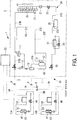
- FIG. 1 a refrigerant circuit diagram of a multi-type air-conditioning device 1 according to the present embodiment is illustrated.
- the multi-type air-conditioning device 1 is configured with a single outdoor unit 3, gas-side piping 5 and liquid-side piping 7 leading from the outdoor unit 3, and a plurality of indoor units 11A and 11B connected in parallel via branching devices 9 between the gas-side piping 5 and the liquid-side piping 7.
- the outdoor unit 3 includes, an inverter-driven compressor 13 configured to compress a refrigerant, an oil separator 15 configured to separate refrigeration oil from a refrigerant gas, a four-way selector valve 17 configured to switch a circulation direction of the refrigerant, an outdoor heat exchanger 19 configured to cause the refrigerant and outside air to exchange heat, a sub-cooling coil 21 formed integrally with the outdoor heat exchanger 19, an outdoor expansion valve for heating (EEVH) 23, a receiver 25 configured to store a liquid refrigerant, a sub-cooling heat exchanger 27 configured to provide subcooling to the liquid refrigerant, an expansion valve for sub-cooling (EEVSC) 29 configured to control a refrigerant amount diverted to the sub-cooling heat exchanger 27, an accumulator 31 configured to separate a liquid portion from the refrigerant gas to be sucked into the compressor 13 and to cause the compressor 13 to suck only a gas portion, a gas-side operation valve 33, and a liquid-side operation valve 35
- refrigerant piping 37 such as discharge piping 37A, gas piping 37B, liquid piping 37C, gas piping 37D, intake piping 37E, and branching piping for sub-cooling 37F to form an outdoor coolant circuit 39.
- an outdoor fan 41 that blows outside air to the outdoor heat exchanger 19 is provided to the outdoor unit 3. Furthermore, an oil return circuit 43 for returning the refrigeration oil separated from a discharged refrigerant gas in the oil separator 15 to the compressor 13 side in predetermined amounts is provided between the intake piping 37E of the compressor 13 and the oil separator 15.
- the gas-side piping 5 and the liquid-side piping 7 are the refrigerant piping 37 connected with the gas-side operation valve 33 and the liquid-side operation valve 35 of the outdoor unit 3, respectively.
- a length of the gas-side piping 5 is set according to a distance between the outdoor unit 3 and the indoor unit 11A connected therewith, and a length of the liquid-side piping 7 is set according to a distance between the outdoor unit 3 and the indoor unit 11B connected therewith, during onsite installation work.
- An appropriate number of the branching devices 9 are disposed midway on the gas-side piping 5 and the liquid-side piping 7, and an appropriate number of the indoor units 11A and 11B are each connected via the branching devices 9. As a result, a refrigeration cycle 45 of one hermetically sealed system is configured.
- the indoor units 11A and 11B each include an indoor heat exchanger 47 that causes the refrigerant and inside air to exchange heat and thus performs indoor air conditioning, an indoor expansion valve for cooling (EEVC) 49, and an indoor fan 51 that circulates the inside air via the indoor heat exchanger 47.
- the indoor unit 11A is connected with the branching devices 9 via branched gas-side piping 5A and branched liquid-side piping 7A on the indoor side
- the indoor unit 11B is connected with the branching devices 9 via branched gas-side piping 5B and branched liquid-side piping 7B on the indoor side.
- An outdoor control unit 53 is provided in the outdoor unit 3, and an indoor control unit 55 is provided in each of the indoor units 11A and 11B.
- Each of the outdoor control unit 53 and the indoor control unit 55 is configured with, for example, a central processing unit (CPU), a random access memory (RAM), a read only memory (ROM), a computer readable recording medium, and the like. Further, for example, a sequence of processing for performing various functions is stored on a recording medium or the like in the form of a program, and the various functions are performed by the CPU loading this program from the recording medium, storing the program into the RAM or the like, and executing information processing and calculation processing.
- the program may be preinstalled in the ROM or other recording medium, may be provided in the form of being stored in a computer readable recording medium, or may be distributed through wired/wireless communication means, for example.
- Examples of the computer readable recording medium include a magnetic disk, a magneto-optical disk, a CD-ROM, a DVD-ROM, a semiconductor memory, and the like.
- the indoor control unit 55 is configured to transmit control information necessary for the outdoor control unit 53 based on information inputted from a suction air temperature sensor 63, a discharge air temperature sensor, a heat exchange temperature sensor, a heat exchange outlet temperature sensor, and the like, and to appropriately control a degree of opening of an indoor expansion valve 49, an air flow rate by the indoor fan 51, or the like. Additionally, the indoor control unit 55 is configured to calculate required capacity from a difference between an indoor temperature detected by the suction air temperature sensor 63 and a set temperature, and to transmit the required capacity to the outdoor control unit 53.
- the outdoor control unit 53 is configured to be capable of appropriately controlling the number of revolutions of the compressor 13, a degree of opening of the outdoor expansion valve 23, or the like, based on control information from the indoor control unit 55, and inputted information from an outside air temperature sensor 57, a high-pressure sensor 59, a low-pressure sensor 61, and the like, and causing the four-way selector valve 17 to operate in order to switch cooling and heating.
- the outdoor control unit 53 is configured to be capable of controlling high pressure to be set to heating target high pressure (target pressure) HP during heating operation based on detected values by the high-pressure sensor 59, and controlling low pressure to be set to cooling target low pressure (target pressure) LP during cooling operation based on detected values by the low-pressure sensor 61.
- the cooling operation is performed as follows.
- a high-temperature, high-pressure refrigerant gas compressed by the compressor 13 is discharged to the discharge piping 37A, and refrigeration oil contained in the refrigerant is separated by the oil separator 15.
- the refrigerant gas is circulated toward the gas piping 37B side by the four-way selector valve 17, and subjected to heat exchange with the outside air blown by the outdoor fan 41 to be condensed and liquefied in the outdoor heat exchanger 19.
- This liquid refrigerant passes through the outdoor expansion valve 23 after being further cooled by the sub-cooling coil 21, and is temporarily stored in the receiver 25.
- Part of the liquid refrigerant whose circulation amount is adjusted by the receiver 25 is diverted to the branching piping for sub-cooling 37F in a process of circulation through the sub-cooling heat exchanger 27 via the liquid piping 37C, is subjected to heat exchange with the refrigerant adiabatically expanded by the expansion valve for sub-cooling (EEVSC) 29, and is given a degree of subcooling.
- EVSC expansion valve for sub-cooling
- This liquid refrigerant is introduced from the outdoor unit 3 to the liquid-side piping 7 via the liquid-side operation valve 35, and the liquid refrigerant introduced to the liquid-side piping 7 is further diverted to the branched liquid-side piping 7A and 7B of the respective indoor units 11A and 11B via the branching devices 9.
- the liquid refrigerant diverted to the branched liquid-side piping 7A flows into the indoor unit 11A and the liquid refrigerant diverted to the branched liquid-side piping 7B flows into the indoor unit 11B.
- Each of the liquid refrigerants is adiabatically expanded by the indoor expansion valve (EEVC) 49 to form a gas-liquid two-phase flow, and is introduced into the indoor heat exchanger 47.
- EEVC indoor expansion valve
- the indoor heat exchanger 47 heat is exchanged between the refrigerant and the inside air circulated by the indoor fan 51.
- the inside air is thus cooled and provided for indoor cooling.
- the refrigerants are gasified, flow to the branching device 9 via the branched gas-side piping 5A, 5B, and merge with the refrigerant gas from other indoor unit 11 in the gas-side piping 5.
- the refrigerant gas merged in the gas-side piping 5 is returned once again to the outdoor unit 3, reaches the intake piping 37E via the gas-side operation valve 33, the gas piping 37D, and the four-way selector valve 17, and is merged with the refrigerant gas from the branching piping for sub-cooling 37F.
- the merged gas is subsequently introduced into the accumulator 31.
- the liquid portion contained in the refrigerant gas is separated, and only the gas portion is sucked into the compressor 13.
- This refrigerant is once again compressed in the compressor 13.
- the cooling operation is performed by repeating the cycle described above.
- the heating operation is performed as follows.
- a high-temperature, high-pressure refrigerant gas compressed by the compressor 13 is discharged to the discharge piping 37A, and refrigeration oil contained in the refrigerant is separated by the oil separator 15.
- the refrigerant is then circulated to the gas piping 37D side by the four-way selector valve 17.
- This refrigerant is led out from the outdoor unit 3 via the gas-side operation valve 33 and the gas-side piping 5, and is further introduced into the indoor units 11A and 11B via the branching devices 9 and the branched gas-side piping 5A and 5B on the indoor side, respectively.
- the high-temperature, high-pressure refrigerant gas introduced into either the indoor unit 11A or 11B is subjected to heat exchange with the inside air circulated by the indoor fan 51 in the indoor heat exchanger 47, and the inside air is thus heated and provided for indoor heating.
- the liquid refrigerant condensed in the indoor heat exchanger 47 reaches the branching device 9 via the indoor expansion valve (EEVC) 49 and either the branched liquid-side piping 7A or 7B, and is merged with the refrigerant from other indoor unit 11.
- the merged refrigerant is subsequently returned to the outdoor unit 3 via the liquid-side piping 7.
- the refrigerant returned to the outdoor unit 3 reaches the sub-cooling heat exchanger 27 via the liquid-side operation valve 35 and the liquid piping 37C, is given subcooling as in the case of cooling operation, is subsequently introduced into and temporarily stored in the receiver 25, and thus a circulation amount of the refrigerant is adjusted.
- This liquid refrigerant is provided to, via the liquid piping 37C, the outdoor expansion valve (EEVH) 23, is adiabatically expanded therein, and is subsequently introduced into the outdoor heat exchanger 19 via the sub-cooling coil 21.
- EEVH outdoor expansion valve
- This refrigerant circulates from the outdoor heat exchanger 19 via the gas piping 37B, the four-way selector valve 17, the intake piping 37E and is merged with the refrigerant from the branching piping for sub-cooling 37F.
- the merged refrigerant is subsequently introduced into the accumulator 31.
- the liquid portion contained in the refrigerant gas is separated, and only the gas portion is sucked into the compressor 13 and once again compressed in the compressor 13.
- the heating operation is performed by repeating the cycle described above.
- a type of the compressor 13, compressor oil, or the like needs to be changed depending on a type of refrigerant to be used for the multi-type air-conditioning device 1 (hereinafter referred to as a "refrigerant to be used").
- a refrigerant to be used a type of refrigerant to be used for the multi-type air-conditioning device 1
- specifications of the outdoor unit 3 including the compressor 13 needs to be modified depending on the type of refrigerant to be used.
- main constituent elements of the indoor unit 11 are the indoor heat exchanger 47, indoor expansion valve 49, indoor fan 51, and the like, in a case that a refrigerant to be used is switched between R410A and R32, for example, it is possible to share and use the indoor unit 11.
- the indoor unit 11 is capable of supporting the refrigerant to be used without modifying a hardware configuration thereof. However, control over the indoor unit 11 needs to be modified.
- the multi-type air-conditioning device 1 performs control corresponding to a refrigerant to be used in which control over the indoor unit 11 is modified according to a type of refrigerant to be used.
- FIG. 2 is a block diagram illustrating an electrical configuration of the outdoor control unit 53 and the indoor control unit 55 according to the control corresponding to a refrigerant to be used.
- the outdoor control unit 53 includes a refrigerant type setting unit 60, a refrigerant type signal generating unit 62, and a transmission unit 64.
- the refrigerant type setting unit 60 is, as an example, a dip switch, and a type of refrigerant to be used is set by switching the switch. Note that, the refrigerant type setting unit 60 is not limited to the dip switch and, for example, may be software in which refrigerant types are defined, and may be information stored in a storage unit (not illustrated).
- the refrigerant type signal generating unit 62 reads the type of refrigerant to be used from the refrigerant type setting unit 60 and generates a refrigerant type signal indicating the read type.
- the transmission unit 64 transmits the refrigerant type signal to the indoor control unit 55. Note that, the refrigerant type signal is transmitted from the transmission unit 64 to the plurality of indoor control units 55 provided in the respective indoor units 11 at the same time.
- the indoor control unit 55 includes a reception unit 66, a control setting unit 68, a storage unit 70, and a control unit 72.
- the reception unit 66 receives the refrigerant type signal from the outdoor control unit 53.
- the control setting unit 68 sets control over the indoor unit 11 corresponding to the type of refrigerant to be used indicated by the refrigerant type signal. Note that, control information idicating contents of control corresponding to a type of refrigerant to be used is stored in the storage unit 70. The control setting unit 68 reads out the contents of control corresponding to the type of refrigerant to be used from the storage unit 70, and sets the control over the indoor unit 11 based on the contents of control.
- the control unit 72 controls the indoor unit 11 based on the contents of control set by the control setting unit 68.
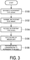
- FIG. 3 is a flowchart depicting a process flow according to the control corresponding to a refrigerant to be used according to the present embodiment.
- the control corresponding to a refrigerant to be used is, for example, performed when a new multi-type air-conditioning device 1 installed in a building or the like is operated for the first time. Additionally, without being limited to the above-described case, the control corresponding to a refrigerant to be used may be performed when the multi-type air-conditioning device 1 is operated for the first time after power of the indoor unit 11 or the outdoor unit 3 is turned on from off, a new indoor unit 11 is added, the type of refrigerant to be used is changed, or the like.
- step 100 the outdoor control unit 53 reads a type of refrigerant to be used and generates a refrigerant type signal.
- the outdoor control unit 53 transmits the refrigerant type signal to the indoor control unit 55.
- the refrigerant type signal from the outdoor control unit 53 is received by the indoor control unit 55 of each of the indoor units 11.
- the outdoor control unit 53 is caused to grasp the type of refrigerant to be used, and the refrigerant type signal is transmitted to all the connected indoor control units 55, from the viewpoint of processing efficiency.
- control corresponding to the type of refrigerant indicated by the refrigerant type signal is set by the indoor control unit 55.
- the set contents of control are transmitted from the indoor control unit 55 to the outdoor control unit 53. Accordingly, since the outdoor control unit 53 is capable of grasping the contents of control by the indoor control unit 55, the outdoor control unit 53 is capable of performing control according to the contents of control by the indoor control unit 55, as in a case of a coolant leakage detection function described later.
- the indoor control unit 55 performs control according to the refrigerant to be used based on the setting in step 106.
- the indoor control unit 55 sets function necessity for coolant leakage detection (hereinafter, referred to as "coolant leakage detection function") according to the type of refrigerant to be used.
- coolant leakage detection function denotes, for example, an external coolant leakage detector, a reception function of a detection result by the coolant leakage detector, a warning function for a user when coolant leakage is detected, or the like.
- an amount of refrigerant to be used is large, compared to an air-conditioning device in which the outdoor unit 3 and the indoor unit 11 have a one-to-one relation.
- an amount of leakage becomes large in a case of the coolant leakage.
- a safety device such as the coolant leakage detector needs to be used suitably according to the type of refrigerant to be used.
- R410A is a non-combustible refrigerant
- R32 is a slightly combustible refrigerant. Accordingly, when the refrigerant to be used is R410A, the coolant leakage detection function is unnecessary, and thus the function is turned off. Meanwhile, when the refrigerant to be used is R410A, the coolant leakage detection function is necessary, and thus the function is turned on. Accordingly, the multi-type air-conditioning device 1 is capable of suitably controlling according to presence or absence of combustibility of the refrigerant to be used.
- the outdoor control unit 53 when the coolant leakage detection function is turned on and the coolant leakage detector detects coolant leakage, the outdoor control unit 53 performs so-called pump-down operation for moving the refrigerant on the indoor unit 11 side to the outdoor unit 3 side, and subsequently stops operation of the multi-type air-conditioning device 1. Additionally, the outdoor control unit 53 closes a valve provided on the refrigerant piping 37 connecting the outdoor unit 3 with the indoor unit 11, or the like.
- the indoor control unit 55 changes a target temperature of the indoor heat exchanger 47 included in the indoor unit 11 according to the type of refrigerant to be used.
- a degree of superheat during cooling operation and a degree of subcooling during heating operation depend on characteristics of the refrigerant to be used, a degree of superheat and a degree of subcooling are set suitably according to the type of refrigerant to be used. Note that a target temperature corresponding to the refrigerant to be used is stored in the storage unit 70.
- the indoor control unit 55 changes an air flow rate of the indoor fan 51 included in the indoor unit 11 according to the type of refrigerant to be used.
- the air flow rate needed depends on the characteristics of the refrigerant to be used, a suitable air flow rate corresponding to the type of refrigerant to be used is set. Note that the air flow rate corresponding to the refrigerant to be used is, for example, stored in the storage unit 70 as the number of revolutions of the indoor fan 51.
- the multi-type air-conditioning device 1 includes the outdoor control unit 53 provided in the outdoor unit 3 and configured to control the outdoor unit, and the plurality of indoor control units 55 provided in the respective indoor units 11 and configured to control the respective indoor units 11. Additionally, the outdoor control unit 53 transmits the refrigerant type signal indicating the type of refrigerant to be used to the plurality of indoor control units 55. The indoor control unit 55 performs control corresponding to the type of refrigerant to be used indicated by the refrigerant type signal received from the outdoor control unit 53.
- the refrigerant type signal is transmitted from the outdoor control unit 53 to the plurality of indoor control units 55, and the control corresponding to the type of refrigerant indicated by the refrigerant type signal is performed by the indoor control unit 55.
- the multi-type air-conditioning device 1 allows an easy use of the plurality of indoor units 11 connected with the outdoor unit 3 in accordance with the type of refrigerant.
- the outdoor control unit 53 may transmit a function necessity signal indicating necessity of a function corresponding to a type of refrigerant, instead of a refrigerant type signal, to the indoor control unit 55.
- a function whose necessity is indicated by the function necessity signal is, for example, a coolant leakage detection function, but is not limited thereto, and may be another function as long as the function needs to be changed according to a type of refrigerant.
- Determination of function necessity is performed by the outdoor control unit 53 according to a type of refrigerant.
- the outdoor control unit 53 stores table data indicating necessity of functions corresponding to a type of refrigerant, and refers to the table data to determine function necessity every time a type of refrigerant is set.
- an administrator of the multi-type air-conditioning device 1 may input information indicating function necessity corresponding to a type of refrigerant to the outdoor control unit 53.
- the outdoor control unit 53 may transmit a function necessity signal to the indoor control unit 55 based on the inputted information.
- control corresponding to the function indicated by the received function necessity signal is performed by the indoor control unit 55.
- the indoor control unit 55 starts performing a function needed by the function necessity signal unless the function is performed. In a case that a function not needed by the function necessity signal is being performed, the indoor control unit 55 stops performing the function. On the other hand, in a case that the function needed by the function necessity signal is being performed, the indoor control unit 55 continues to perform the function.
- control corresponding to a refrigerant to be used described in the aforementioned embodiments is also an example, and an unnecessary step may be deleted, a new step may be added, and the processing order may be changed without deviating from the gist of the present invention.
Landscapes
- Engineering & Computer Science (AREA)
- Mechanical Engineering (AREA)
- General Engineering & Computer Science (AREA)
- Physics & Mathematics (AREA)
- Chemical & Material Sciences (AREA)
- Combustion & Propulsion (AREA)
- Thermal Sciences (AREA)
- Fluid Mechanics (AREA)
- Air Conditioning Control Device (AREA)
Abstract
Description
- The present invention relates to an air-conditioning device, and a method for controlling an air-conditioning device.
- For example, in an air-conditioning device used in buildings, commercial facilities, or the like in which an outdoor unit is connected with a plurality of indoor units (hereinafter, referred to as a "multi-type air-conditioning device"), the outdoor unit and the indoor units are separately sold in some cases. In this case, since a plurality of indoor units are freely selectable according to customer demands, the number of varieties (types or capacities) tends to increase. Accordingly, an outdoor unit corresponding to a selected indoor unit is selected.
- In addition, characteristics, safety measures, or the like, of an air-conditioning device depend on a type of refrigerant to be used for the multi-type air-conditioning device. For example, although R410 refrigerant is incombustible, R32 refrigerant is slightly combustible. Thus, the air-conditioning device needs to detect coolant leakage.
- Accordingly, an outdoor unit or an indoor unit corresponding to a type of refrigerant needs to be used. However, since there is a large variety of indoor units, the number of varieties becomes enormously large when the indoor units are further caused to correspond to a type of refrigerant.
- As varieties of indoor units increase, supply sides such as manufacturers and sales companies of indoor units increase types of the indoor units while reducing an amount of production for each product type, inventory management becomes complicated, and thus costs rise. As a result, a unit price of the indoor unit rises.
- Note that, a type of a compressor, compressor oil, or the like, also needs to be changed according to a type of refrigerant. Accordingly, a hardware configuration of an outdoor unit equipped with a compressor needs to be modified according to a type of refrigerant in some cases. Meanwhile, as for an indoor unit, although there is no need for modifying a hardware configuration, a control program needs to be modified in some cases.
-
Patent Document 1 describes an air conditioning control device that is equipped with a control program storing means for storing a plurality of control programs for controlling a refrigeration cycle corresponding to a type of refrigerant, and controls the refrigeration cycle corresponding to the type of refrigerant based on the control programs stored in the control program storing means. - The air conditioning control device described in
Patent Document 1 determines the type of refrigerant using a CPU for controlling the indoor unit. This determination method is performed by calculating a pressure-enthalpy ratio of a refrigerant in a compression process based on a suction temperature, a suction pressure, a discharge temperature, and a discharge pressure of a compressor, and comparing the ratio with pressure-enthalpy ratio data corresponding to the type of refrigerant. - Patent Document 1:
JP 08-254363 A - As described above, the air conditioning control device described in
Patent Document 1 determines the type of refrigerant using the CPU for controlling the indoor unit. In addition,Patent Document 1 describes that the indoor unit selects control data according to the type of refrigerant, transmits the control data or refrigerant type information to an outdoor unit, and the outdoor unit stores or specifies the received control data or refrigerant type information. - In other words, the air conditioning control device described in
Patent Document 1 determines the type of refrigerant and sets the control data on the indoor unit side, and transmits these information to the outdoor unit side. - However, when the configuration described in
Patent Document 1 in which the information on the type of refrigerant or the like is transmitted from the indoor unit side to the outdoor unit side is applied to a multi-type air-conditioning device equipped with a plurality of indoor units having different varieties, information processing on the outdoor unit becomes complicated. - Additionally, in a case where the indoor unit side performs the process of determining the type of refrigerant, the plurality of indoor units wastefully perform the same processing. Further, there is a possibility that an error occurs in the determination of the type of refrigerant in the indoor unit side and information indicating a different type of refrigerant is transmitted to the outdoor unit.
- In light of the foregoing, an object of the present invention is to provide an air-conditioning device and a method for controlling an air-conditioning device that allow an easy use of a plurality of indoor units in accordance with the type of refrigerant.
- In order to solve the above-described problems, the air-conditioning device and the method for controlling an air-conditioning device according to the present invention adopt the following means.
- An air-conditioning device according to a first aspect of the present invention includes: an outdoor unit, a plurality of indoor units connected with the outdoor unit via refrigerant piping, an outdoor control means provided in the outdoor unit and configured to control the outdoor unit, and a plurality of indoor control means provided in the respective indoor units and configured to control the respective indoor units, in which the outdoor control means transmits a refrigerant type signal indicating a type of refrigerant to be used or a function necessity signal indicating function necessity corresponding to a type of refrigerant to the plurality of indoor control means, and the indoor control means performs control corresponding to a type of refrigerant indicated by the refrigerant type signal received from the outdoor control means or control corresponding to a function indicated by the function necessity signal.
- The air-conditioning device according to this configuration includes the outdoor unit, and the plurality of indoor units connected with the outdoor unit via the refrigerant piping. The outdoor unit is controlled by the outdoor control means provided in the outdoor unit. Each of the indoor units is controlled by the indoor control means provided in each of the indoor units.
- The indoor unit connected with the outdoor unit needs to be controlled according to the refrigerant to be used.
- Accordingly, the refrigerant type signal indicating the type of refrigerant to be used, or the function necessity signal indicating the function necessity corresponding to the type of refrigerant is transmitted from the outdoor control means to the plurality of indoor control means. Control corresponding to the type of refrigerant indicated by the refrigerant type signal received from the outdoor control means is performed by the indoor control means. Additionally, control corresponding to the function indicated by the function necessity signal is performed by the indoor control means.
- As described above, the refrigerant type signal or the function necessity signal is transmitted from the outdoor control means to the plurality of indoor control means, and the control corresponding to the type of refrigerant indicated by the refrigerant type signal or the control corresponding to the function indicated by the function necessity signal is performed by the indoor control device. Thus, this configuration allows an easy use of the plurality of indoor units in accordance with the type of refrigerant.
- In the above-described first aspect, the indoor control means may set function necessity for coolant leakage detection according to the type of refrigerant.
- According to this configuration, when a refrigerant is incombustible, the function for coolant leakage detection is turned off, and when the refrigerant is combustible, the function for coolant leakage detection is turned on. Thus, suitable control is possible according to presence or absence of combustibility of the refrigerant.
- In the above-described first aspect, the indoor control means may change a target temperature of a heat exchanger included in the indoor unit according to the type of refrigerant.
- According to this configuration, since a degree of superheat during cooling operation and a degree of subcooling during heating operation depend on characteristics of the refrigerant, suitable control according to the type of refrigerant is possible.
- In the above-described first aspect, the indoor control means may change an air flow rate of a fan included in the indoor unit according to the type of refrigerant.
- According to this configuration, since the air flow rate needed depends on the characteristics of the refrigerant, suitable control according to the type of refrigerant is possible.
- A method for controlling an air-conditioning device according to a second aspect of the present invention is a method for controlling an air-conditioning device including an outdoor unit, a plurality of indoor units connected with the outdoor unit via refrigerant piping, an outdoor control means provided in the outdoor unit and configured to control the outdoor unit, and a plurality of indoor control means provided in the respective indoor units and configured to control the respective indoor units. In the stated method, the outdoor control means transmits a refrigerant type signal indicating a type of refrigerant to be used or a function necessity signal indicating function necessity corresponding to a type of refrigerant to the plurality of indoor control means, and the indoor control means performs control corresponding to a type of refrigerant indicated by the refrigerant type signal received from the outdoor control means or control corresponding to a function indicated by the function necessity signal.
- According to the present invention, an effect allowing an easy use of a plurality of indoor units in accordance with a type of refrigerant is exhibited.
-
-
FIG. 1 is a refrigerant circuit diagram of a multi-type air-conditioning device according to a first embodiment of the present invention. -
FIG. 2 is a block diagram illustrating an electrical configuration of an outdoor control unit and an indoor control unit according to control corresponding to a refrigerant to be used according to the embodiment of the present invention. -
FIG. 3 is a flowchart depicting a process flow according to the control corresponding to a refrigerant to be used according to the embodiment of the present invention. - Embodiments of an air-conditioning device and a method for controlling an air-conditioning device according to the present invention are described below with reference to the accompanying drawings.
- In
FIG. 1 , a refrigerant circuit diagram of a multi-type air-conditioning device 1 according to the present embodiment is illustrated. - The multi-type air-
conditioning device 1 is configured with a single outdoor unit 3, gas-side piping 5 and liquid-side piping 7 leading from the outdoor unit 3, and a plurality ofindoor units devices 9 between the gas-side piping 5 and the liquid-side piping 7. - The outdoor unit 3 includes, an inverter-driven
compressor 13 configured to compress a refrigerant, anoil separator 15 configured to separate refrigeration oil from a refrigerant gas, a four-way selector valve 17 configured to switch a circulation direction of the refrigerant, anoutdoor heat exchanger 19 configured to cause the refrigerant and outside air to exchange heat, asub-cooling coil 21 formed integrally with theoutdoor heat exchanger 19, an outdoor expansion valve for heating (EEVH) 23, areceiver 25 configured to store a liquid refrigerant, asub-cooling heat exchanger 27 configured to provide subcooling to the liquid refrigerant, an expansion valve for sub-cooling (EEVSC) 29 configured to control a refrigerant amount diverted to thesub-cooling heat exchanger 27, anaccumulator 31 configured to separate a liquid portion from the refrigerant gas to be sucked into thecompressor 13 and to cause thecompressor 13 to suck only a gas portion, a gas-side operation valve 33, and a liquid-side operation valve 35. - Each of the above-described devices on the outdoor unit 3 side is connected as is well known via refrigerant piping 37 such as
discharge piping 37A,gas piping 37B,liquid piping 37C,gas piping 37D,intake piping 37E, and branching piping forsub-cooling 37F to form anoutdoor coolant circuit 39. - Further, an
outdoor fan 41 that blows outside air to theoutdoor heat exchanger 19 is provided to the outdoor unit 3. Furthermore, anoil return circuit 43 for returning the refrigeration oil separated from a discharged refrigerant gas in theoil separator 15 to thecompressor 13 side in predetermined amounts is provided between theintake piping 37E of thecompressor 13 and theoil separator 15. - The gas-
side piping 5 and the liquid-side piping 7 are the refrigerant piping 37 connected with the gas-side operation valve 33 and the liquid-side operation valve 35 of the outdoor unit 3, respectively. A length of the gas-side piping 5 is set according to a distance between the outdoor unit 3 and theindoor unit 11A connected therewith, and a length of the liquid-side piping 7 is set according to a distance between the outdoor unit 3 and theindoor unit 11B connected therewith, during onsite installation work. An appropriate number of the branchingdevices 9 are disposed midway on the gas-side piping 5 and the liquid-side piping 7, and an appropriate number of theindoor units devices 9. As a result, arefrigeration cycle 45 of one hermetically sealed system is configured. - The
indoor units indoor heat exchanger 47 that causes the refrigerant and inside air to exchange heat and thus performs indoor air conditioning, an indoor expansion valve for cooling (EEVC) 49, and anindoor fan 51 that circulates the inside air via theindoor heat exchanger 47. Theindoor unit 11A is connected with the branchingdevices 9 via branched gas-side piping 5A and branched liquid-side piping 7A on the indoor side, and theindoor unit 11B is connected with the branchingdevices 9 via branched gas-side piping 5B and branched liquid-side piping 7B on the indoor side. - An
outdoor control unit 53 is provided in the outdoor unit 3, and anindoor control unit 55 is provided in each of theindoor units - Each of the
outdoor control unit 53 and theindoor control unit 55 is configured with, for example, a central processing unit (CPU), a random access memory (RAM), a read only memory (ROM), a computer readable recording medium, and the like. Further, for example, a sequence of processing for performing various functions is stored on a recording medium or the like in the form of a program, and the various functions are performed by the CPU loading this program from the recording medium, storing the program into the RAM or the like, and executing information processing and calculation processing. Note that the program may be preinstalled in the ROM or other recording medium, may be provided in the form of being stored in a computer readable recording medium, or may be distributed through wired/wireless communication means, for example. Examples of the computer readable recording medium include a magnetic disk, a magneto-optical disk, a CD-ROM, a DVD-ROM, a semiconductor memory, and the like. - The
indoor control unit 55 is configured to transmit control information necessary for theoutdoor control unit 53 based on information inputted from a suctionair temperature sensor 63, a discharge air temperature sensor, a heat exchange temperature sensor, a heat exchange outlet temperature sensor, and the like, and to appropriately control a degree of opening of anindoor expansion valve 49, an air flow rate by theindoor fan 51, or the like. Additionally, theindoor control unit 55 is configured to calculate required capacity from a difference between an indoor temperature detected by the suctionair temperature sensor 63 and a set temperature, and to transmit the required capacity to theoutdoor control unit 53. - The
outdoor control unit 53 is configured to be capable of appropriately controlling the number of revolutions of thecompressor 13, a degree of opening of theoutdoor expansion valve 23, or the like, based on control information from theindoor control unit 55, and inputted information from an outsideair temperature sensor 57, a high-pressure sensor 59, a low-pressure sensor 61, and the like, and causing the four-way selector valve 17 to operate in order to switch cooling and heating. - Additionally, the
outdoor control unit 53 is configured to be capable of controlling high pressure to be set to heating target high pressure (target pressure) HP during heating operation based on detected values by the high-pressure sensor 59, and controlling low pressure to be set to cooling target low pressure (target pressure) LP during cooling operation based on detected values by the low-pressure sensor 61. - In the above-described multi-type air-
conditioning device 1, the cooling operation is performed as follows. - A high-temperature, high-pressure refrigerant gas compressed by the
compressor 13 is discharged to the discharge piping 37A, and refrigeration oil contained in the refrigerant is separated by theoil separator 15. - Subsequently, the refrigerant gas is circulated toward the gas piping 37B side by the four-
way selector valve 17, and subjected to heat exchange with the outside air blown by theoutdoor fan 41 to be condensed and liquefied in theoutdoor heat exchanger 19. - This liquid refrigerant passes through the
outdoor expansion valve 23 after being further cooled by thesub-cooling coil 21, and is temporarily stored in thereceiver 25. - Part of the liquid refrigerant whose circulation amount is adjusted by the
receiver 25 is diverted to the branching piping for sub-cooling 37F in a process of circulation through thesub-cooling heat exchanger 27 via theliquid piping 37C, is subjected to heat exchange with the refrigerant adiabatically expanded by the expansion valve for sub-cooling (EEVSC) 29, and is given a degree of subcooling. - This liquid refrigerant is introduced from the outdoor unit 3 to the liquid-side piping 7 via the liquid-
side operation valve 35, and the liquid refrigerant introduced to the liquid-side piping 7 is further diverted to the branched liquid-side piping indoor units devices 9. - The liquid refrigerant diverted to the branched liquid-
side piping 7A flows into theindoor unit 11A and the liquid refrigerant diverted to the branched liquid-side piping 7B flows into theindoor unit 11B. Each of the liquid refrigerants is adiabatically expanded by the indoor expansion valve (EEVC) 49 to form a gas-liquid two-phase flow, and is introduced into theindoor heat exchanger 47. - In the
indoor heat exchanger 47, heat is exchanged between the refrigerant and the inside air circulated by theindoor fan 51. The inside air is thus cooled and provided for indoor cooling. On the other hand, the refrigerants are gasified, flow to the branchingdevice 9 via the branched gas-side piping side piping 5. - The refrigerant gas merged in the gas-
side piping 5 is returned once again to the outdoor unit 3, reaches theintake piping 37E via the gas-side operation valve 33, thegas piping 37D, and the four-way selector valve 17, and is merged with the refrigerant gas from the branching piping forsub-cooling 37F. The merged gas is subsequently introduced into theaccumulator 31. - In the
accumulator 31, the liquid portion contained in the refrigerant gas is separated, and only the gas portion is sucked into thecompressor 13. - This refrigerant is once again compressed in the
compressor 13. The cooling operation is performed by repeating the cycle described above. - On the other hand, the heating operation is performed as follows.
- A high-temperature, high-pressure refrigerant gas compressed by the
compressor 13 is discharged to the discharge piping 37A, and refrigeration oil contained in the refrigerant is separated by theoil separator 15. The refrigerant is then circulated to thegas piping 37D side by the four-way selector valve 17. - This refrigerant is led out from the outdoor unit 3 via the gas-
side operation valve 33 and the gas-side piping 5, and is further introduced into theindoor units devices 9 and the branched gas-side piping - The high-temperature, high-pressure refrigerant gas introduced into either the
indoor unit indoor fan 51 in theindoor heat exchanger 47, and the inside air is thus heated and provided for indoor heating. - The liquid refrigerant condensed in the
indoor heat exchanger 47 reaches the branchingdevice 9 via the indoor expansion valve (EEVC) 49 and either the branched liquid-side piping - The refrigerant returned to the outdoor unit 3 reaches the
sub-cooling heat exchanger 27 via the liquid-side operation valve 35 and theliquid piping 37C, is given subcooling as in the case of cooling operation, is subsequently introduced into and temporarily stored in thereceiver 25, and thus a circulation amount of the refrigerant is adjusted. - This liquid refrigerant is provided to, via the
liquid piping 37C, the outdoor expansion valve (EEVH) 23, is adiabatically expanded therein, and is subsequently introduced into theoutdoor heat exchanger 19 via thesub-cooling coil 21. - In the
outdoor heat exchanger 19, heat is exchanged between the refrigerant and the outside air blown from theoutdoor fan 41, and the refrigerant absorbs the heat from the outside air and is evaporated and gasified. - This refrigerant circulates from the
outdoor heat exchanger 19 via thegas piping 37B, the four-way selector valve 17, theintake piping 37E and is merged with the refrigerant from the branching piping forsub-cooling 37F. The merged refrigerant is subsequently introduced into theaccumulator 31. In theaccumulator 31, the liquid portion contained in the refrigerant gas is separated, and only the gas portion is sucked into thecompressor 13 and once again compressed in thecompressor 13. The heating operation is performed by repeating the cycle described above. - Here, a type of the
compressor 13, compressor oil, or the like needs to be changed depending on a type of refrigerant to be used for the multi-type air-conditioning device 1 (hereinafter referred to as a "refrigerant to be used"). Thus, specifications of the outdoor unit 3 including thecompressor 13 needs to be modified depending on the type of refrigerant to be used. On the other hand, since main constituent elements of the indoor unit 11 are theindoor heat exchanger 47,indoor expansion valve 49,indoor fan 51, and the like, in a case that a refrigerant to be used is switched between R410A and R32, for example, it is possible to share and use the indoor unit 11. - That is to say, while a hardware configuration of the outdoor unit 3 needs to be modified according to the type of refrigerant to be used, the indoor unit 11 is capable of supporting the refrigerant to be used without modifying a hardware configuration thereof. However, control over the indoor unit 11 needs to be modified.
- The multi-type air-
conditioning device 1 according to the present embodiment performs control corresponding to a refrigerant to be used in which control over the indoor unit 11 is modified according to a type of refrigerant to be used. -
FIG. 2 is a block diagram illustrating an electrical configuration of theoutdoor control unit 53 and theindoor control unit 55 according to the control corresponding to a refrigerant to be used. - The
outdoor control unit 53 includes a refrigeranttype setting unit 60, a refrigerant typesignal generating unit 62, and atransmission unit 64. - The refrigerant
type setting unit 60 is, as an example, a dip switch, and a type of refrigerant to be used is set by switching the switch. Note that, the refrigeranttype setting unit 60 is not limited to the dip switch and, for example, may be software in which refrigerant types are defined, and may be information stored in a storage unit (not illustrated). - The refrigerant type
signal generating unit 62 reads the type of refrigerant to be used from the refrigeranttype setting unit 60 and generates a refrigerant type signal indicating the read type. - The
transmission unit 64 transmits the refrigerant type signal to theindoor control unit 55. Note that, the refrigerant type signal is transmitted from thetransmission unit 64 to the plurality ofindoor control units 55 provided in the respective indoor units 11 at the same time. - The
indoor control unit 55 includes areception unit 66, acontrol setting unit 68, astorage unit 70, and acontrol unit 72. - The
reception unit 66 receives the refrigerant type signal from theoutdoor control unit 53. - The
control setting unit 68 sets control over the indoor unit 11 corresponding to the type of refrigerant to be used indicated by the refrigerant type signal. Note that, control information idicating contents of control corresponding to a type of refrigerant to be used is stored in thestorage unit 70. Thecontrol setting unit 68 reads out the contents of control corresponding to the type of refrigerant to be used from thestorage unit 70, and sets the control over the indoor unit 11 based on the contents of control. - The
control unit 72 controls the indoor unit 11 based on the contents of control set by thecontrol setting unit 68. -
FIG. 3 is a flowchart depicting a process flow according to the control corresponding to a refrigerant to be used according to the present embodiment. Note that, the control corresponding to a refrigerant to be used is, for example, performed when a new multi-type air-conditioning device 1 installed in a building or the like is operated for the first time. Additionally, without being limited to the above-described case, the control corresponding to a refrigerant to be used may be performed when the multi-type air-conditioning device 1 is operated for the first time after power of the indoor unit 11 or the outdoor unit 3 is turned on from off, a new indoor unit 11 is added, the type of refrigerant to be used is changed, or the like. - First, in
step 100, theoutdoor control unit 53 reads a type of refrigerant to be used and generates a refrigerant type signal. - In the next step 102, the
outdoor control unit 53 transmits the refrigerant type signal to theindoor control unit 55. - In the next step 104, the refrigerant type signal from the
outdoor control unit 53 is received by theindoor control unit 55 of each of the indoor units 11. - As described above, in the multi-type air-
conditioning device 1 in which the plurality of indoor units 11 are connected with the single outdoor unit 3, it is appropriate that theoutdoor control unit 53 is caused to grasp the type of refrigerant to be used, and the refrigerant type signal is transmitted to all the connectedindoor control units 55, from the viewpoint of processing efficiency. - In the next step 106, control corresponding to the type of refrigerant indicated by the refrigerant type signal is set by the
indoor control unit 55. Note that, the set contents of control are transmitted from theindoor control unit 55 to theoutdoor control unit 53. Accordingly, since theoutdoor control unit 53 is capable of grasping the contents of control by theindoor control unit 55, theoutdoor control unit 53 is capable of performing control according to the contents of control by theindoor control unit 55, as in a case of a coolant leakage detection function described later. - In the
next step 108, theindoor control unit 55 performs control according to the refrigerant to be used based on the setting in step 106. - Next, a specific example of the contents of control corresponding to the type of refrigerant to be used is described.
- The
indoor control unit 55 sets function necessity for coolant leakage detection (hereinafter, referred to as "coolant leakage detection function") according to the type of refrigerant to be used. - The term "coolant leakage detection function" denotes, for example, an external coolant leakage detector, a reception function of a detection result by the coolant leakage detector, a warning function for a user when coolant leakage is detected, or the like.
- In the multi-type air-
conditioning device 1, an amount of refrigerant to be used is large, compared to an air-conditioning device in which the outdoor unit 3 and the indoor unit 11 have a one-to-one relation. Thus, an amount of leakage becomes large in a case of the coolant leakage. Accordingly, a safety device such as the coolant leakage detector needs to be used suitably according to the type of refrigerant to be used. - For example, while R410A is a non-combustible refrigerant, R32 is a slightly combustible refrigerant. Accordingly, when the refrigerant to be used is R410A, the coolant leakage detection function is unnecessary, and thus the function is turned off. Meanwhile, when the refrigerant to be used is R410A, the coolant leakage detection function is necessary, and thus the function is turned on. Accordingly, the multi-type air-
conditioning device 1 is capable of suitably controlling according to presence or absence of combustibility of the refrigerant to be used. - Note that, when the coolant leakage detection function is turned on and the coolant leakage detector detects coolant leakage, the
outdoor control unit 53 performs so-called pump-down operation for moving the refrigerant on the indoor unit 11 side to the outdoor unit 3 side, and subsequently stops operation of the multi-type air-conditioning device 1. Additionally, theoutdoor control unit 53 closes a valve provided on the refrigerant piping 37 connecting the outdoor unit 3 with the indoor unit 11, or the like. - Further, the
indoor control unit 55 changes a target temperature of theindoor heat exchanger 47 included in the indoor unit 11 according to the type of refrigerant to be used. - Since a degree of superheat during cooling operation and a degree of subcooling during heating operation depend on characteristics of the refrigerant to be used, a degree of superheat and a degree of subcooling are set suitably according to the type of refrigerant to be used. Note that a target temperature corresponding to the refrigerant to be used is stored in the
storage unit 70. - Further, the
indoor control unit 55 changes an air flow rate of theindoor fan 51 included in the indoor unit 11 according to the type of refrigerant to be used. - Since the air flow rate needed depends on the characteristics of the refrigerant to be used, a suitable air flow rate corresponding to the type of refrigerant to be used is set. Note that the air flow rate corresponding to the refrigerant to be used is, for example, stored in the
storage unit 70 as the number of revolutions of theindoor fan 51. - As described above, the multi-type air-
conditioning device 1 according to the present embodiment includes theoutdoor control unit 53 provided in the outdoor unit 3 and configured to control the outdoor unit, and the plurality ofindoor control units 55 provided in the respective indoor units 11 and configured to control the respective indoor units 11. Additionally, theoutdoor control unit 53 transmits the refrigerant type signal indicating the type of refrigerant to be used to the plurality ofindoor control units 55. Theindoor control unit 55 performs control corresponding to the type of refrigerant to be used indicated by the refrigerant type signal received from theoutdoor control unit 53. - As described above, the refrigerant type signal is transmitted from the
outdoor control unit 53 to the plurality ofindoor control units 55, and the control corresponding to the type of refrigerant indicated by the refrigerant type signal is performed by theindoor control unit 55. Thus, the multi-type air-conditioning device 1 according to the present embodiment allows an easy use of the plurality of indoor units 11 connected with the outdoor unit 3 in accordance with the type of refrigerant. - In the above, the present invention has been described using the aforementioned embodiments. However, the technical scope of the present invention is not limited to the scope described in the aforementioned embodiments. Various modifications or improvements can be added to the aforementioned embodiments without deviating from the gist of the invention, and aspects obtained by adding the modifications or improvements are also included within the technical scope of the present invention. Also, the above-described embodiment and the second embodiment may be combined as appropriate.
- For example, the
outdoor control unit 53 may transmit a function necessity signal indicating necessity of a function corresponding to a type of refrigerant, instead of a refrigerant type signal, to theindoor control unit 55. - A function whose necessity is indicated by the function necessity signal is, for example, a coolant leakage detection function, but is not limited thereto, and may be another function as long as the function needs to be changed according to a type of refrigerant.
- Determination of function necessity is performed by the
outdoor control unit 53 according to a type of refrigerant. For example, theoutdoor control unit 53 stores table data indicating necessity of functions corresponding to a type of refrigerant, and refers to the table data to determine function necessity every time a type of refrigerant is set. - Note that, without being limited to the above-described case, an administrator of the multi-type air-
conditioning device 1 may input information indicating function necessity corresponding to a type of refrigerant to theoutdoor control unit 53. Theoutdoor control unit 53 may transmit a function necessity signal to theindoor control unit 55 based on the inputted information. - Additionally, control corresponding to the function indicated by the received function necessity signal is performed by the
indoor control unit 55. - More specifically, the
indoor control unit 55 starts performing a function needed by the function necessity signal unless the function is performed. In a case that a function not needed by the function necessity signal is being performed, theindoor control unit 55 stops performing the function. On the other hand, in a case that the function needed by the function necessity signal is being performed, theindoor control unit 55 continues to perform the function. - Furthermore, the flow of the control corresponding to a refrigerant to be used described in the aforementioned embodiments is also an example, and an unnecessary step may be deleted, a new step may be added, and the processing order may be changed without deviating from the gist of the present invention.
-
- 1 Multi-type air-conditioning device (Air-conditioning device)
- 3 Outdoor unit
- 11 Indoor unit
- 37 Refrigerant piping
- 53 Outdoor control unit (Outdoor control means)
- 55 Indoor control unit (Indoor control means)
Claims (5)
- An air-conditioning device, comprising:an outdoor unit,a plurality of indoor units connected with the outdoor unit via refrigerant piping,an outdoor control means provided in the outdoor unit and configured to control the outdoor unit, anda plurality of indoor control means provided in the respective indoor units and configured to control the respective indoor units,wherein the outdoor control means transmits a refrigerant type signal indicating a type of refrigerant to be used or a function necessity signal indicating function necessity corresponding to a type of refrigerant to the plurality of indoor control means, andthe indoor control means performs control corresponding to a type of refrigerant indicated by the refrigerant type signal received from the outdoor control means or control corresponding to a function indicated by the function necessity signal.
- The air-conditioning device according to claim 1, wherein the indoor control means sets function necessity for coolant leakage detection according to a type of refrigerant.
- The air-conditioning device according to claim 1 2, wherein the indoor control means changes a target temperature of a heat exchanger included in the indoor unit according to a type of refrigerant.
- The air-conditioning device according to any one of claims 1 to 3, wherein the indoor control means changes an air flow rate of a fan included in the indoor unit according to a type of refrigerant.
- A method for controlling an air-conditioning device including an outdoor unit, a plurality of indoor units connected with the outdoor unit via refrigerant piping, an outdoor control means provided in the outdoor unit and configured to control the outdoor unit, and a plurality of indoor control means provided in the respective indoor units and configured to control the respective indoor units, the method comprising:the outdoor control means transmitting a refrigerant type signal indicating a type of refrigerant to be used or a function necessity signal indicating function necessity corresponding to a type of refrigerant to the plurality of indoor control means, andthe indoor control means performing control corresponding to a type of refrigerant indicated by the refrigerant type signal received from the outdoor control means or control corresponding to a function indicated by the function necessity signal.
Applications Claiming Priority (2)
| Application Number | Priority Date | Filing Date | Title |
|---|---|---|---|
| JP2016101280A JP2017207256A (en) | 2016-05-20 | 2016-05-20 | Air conditioner and control method of air conditioner |
| PCT/JP2017/015964 WO2017199683A1 (en) | 2016-05-20 | 2017-04-21 | Air conditioner, and air conditioner control method |
Publications (2)
| Publication Number | Publication Date |
|---|---|
| EP3401612A1 true EP3401612A1 (en) | 2018-11-14 |
| EP3401612A4 EP3401612A4 (en) | 2019-03-27 |
Family
ID=60324930
Family Applications (1)
| Application Number | Title | Priority Date | Filing Date |
|---|---|---|---|
| EP17799114.8A Withdrawn EP3401612A4 (en) | 2016-05-20 | 2017-04-21 | Air conditioner, and air conditioner control method |
Country Status (4)
| Country | Link |
|---|---|
| EP (1) | EP3401612A4 (en) |
| JP (1) | JP2017207256A (en) |
| CN (1) | CN108700328A (en) |
| WO (1) | WO2017199683A1 (en) |
Families Citing this family (5)
| Publication number | Priority date | Publication date | Assignee | Title |
|---|---|---|---|---|
| CN110050159B (en) * | 2017-11-16 | 2021-06-25 | 日立江森自控空调有限公司 | Air conditioner |
| JP6800187B2 (en) * | 2018-08-31 | 2020-12-16 | 日立ジョンソンコントロールズ空調株式会社 | Air conditioner |
| WO2020217380A1 (en) * | 2019-04-25 | 2020-10-29 | 東芝キヤリア株式会社 | Indoor unit of air conditioner and air conditioner |
| JP6904395B2 (en) * | 2019-09-30 | 2021-07-14 | ダイキン工業株式会社 | Refrigeration equipment and heat source unit |
| WO2024134890A1 (en) * | 2022-12-23 | 2024-06-27 | 三菱電機株式会社 | Air-conditioning system and method for controlling same, and program |
Family Cites Families (13)
| Publication number | Priority date | Publication date | Assignee | Title |
|---|---|---|---|---|
| JPH04165268A (en) * | 1990-10-30 | 1992-06-11 | Ebara Corp | Turbo refrigerator |
| JPH04369370A (en) * | 1991-06-14 | 1992-12-22 | Hitachi Ltd | Air conditioner |
| JPH07190535A (en) * | 1993-12-27 | 1995-07-28 | Toshiba Corp | Refrigerating cycle control equipment |
| JPH08254363A (en) | 1995-03-15 | 1996-10-01 | Toshiba Corp | Air conditioning control device |
| JP3952510B2 (en) * | 1996-09-20 | 2007-08-01 | 株式会社日立製作所 | Air conditioner and medium on which operation control program is recorded |
| JP3615039B2 (en) * | 1997-12-05 | 2005-01-26 | 松下電器産業株式会社 | Air conditioner |
| JP2000105034A (en) * | 1998-09-29 | 2000-04-11 | Sanyo Electric Co Ltd | Cooling storage |
| JP3998346B2 (en) * | 1998-10-16 | 2007-10-24 | 三洋電機株式会社 | Air conditioner |
| JP4036288B2 (en) * | 2002-07-11 | 2008-01-23 | 株式会社日立製作所 | Air conditioner |
| JP2004263948A (en) * | 2003-03-03 | 2004-09-24 | Mitsubishi Electric Corp | Air conditioner |
| JP2011094871A (en) * | 2009-10-29 | 2011-05-12 | Mitsubishi Electric Corp | Refrigerating air conditioning device and installation method of the refrigerating air conditioning device |
| JP5565332B2 (en) * | 2011-01-31 | 2014-08-06 | 三菱電機株式会社 | Outdoor unit, indoor unit and air conditioner |
| JP6277832B2 (en) * | 2014-04-03 | 2018-02-14 | ダイキン工業株式会社 | controller |
-
2016
- 2016-05-20 JP JP2016101280A patent/JP2017207256A/en active Pending
-
2017
- 2017-04-21 CN CN201780010518.5A patent/CN108700328A/en active Pending
- 2017-04-21 WO PCT/JP2017/015964 patent/WO2017199683A1/en active Application Filing
- 2017-04-21 EP EP17799114.8A patent/EP3401612A4/en not_active Withdrawn
Also Published As
| Publication number | Publication date |
|---|---|
| WO2017199683A1 (en) | 2017-11-23 |
| JP2017207256A (en) | 2017-11-24 |
| CN108700328A (en) | 2018-10-23 |
| EP3401612A4 (en) | 2019-03-27 |
Similar Documents
| Publication | Publication Date | Title |
|---|---|---|
| US11131490B2 (en) | Refrigeration device having condenser unit connected to compressor unit with on-site pipe interposed therebetween and remote from the compressor unit | |
| EP3683524B1 (en) | Refrigeration apparatus | |
| EP3401612A1 (en) | Air conditioner, and air conditioner control method | |
| EP3026371B1 (en) | Refrigeration cycle apparatus | |
| US20230134047A1 (en) | Refrigeration cycle apparatus and refrigeration apparatus | |
| CN110050159B (en) | Air conditioner | |
| EP3088819A1 (en) | Air conditioning device | |
| KR101901540B1 (en) | Air conditioning device | |
| EP2730863A1 (en) | Refrigeration and air conditioning device and method for controlling refrigeration and air conditioning device | |
| EP2963359A1 (en) | Air conditioning device | |
| JPWO2019053880A1 (en) | Refrigeration air conditioner | |
| JP2011047552A (en) | Refrigerating cycle device and air conditioner | |
| EP3859247A1 (en) | Air-conditioning device, management device, and refrigerant connection pipe | |
| EP3543618A1 (en) | Control device, multi-split air conditioning system provided with same, and control method, and control program | |
| US11448433B2 (en) | Refrigeration apparatus | |
| JP6537629B2 (en) | Air conditioner | |
| EP4343235A1 (en) | Refrigerant leakage detection system | |
| WO2022180821A1 (en) | Refrigeration cycle device | |
| EP3882536A1 (en) | Air conditioner | |
| JP6779361B2 (en) | Air conditioner | |
| JP2022115492A (en) | Air conditioning device |
Legal Events
| Date | Code | Title | Description |
|---|---|---|---|
| STAA | Information on the status of an ep patent application or granted ep patent |
Free format text: STATUS: THE INTERNATIONAL PUBLICATION HAS BEEN MADE |
|
| PUAI | Public reference made under article 153(3) epc to a published international application that has entered the european phase |
Free format text: ORIGINAL CODE: 0009012 |
|
| STAA | Information on the status of an ep patent application or granted ep patent |
Free format text: STATUS: REQUEST FOR EXAMINATION WAS MADE |
|
| 17P | Request for examination filed |
Effective date: 20180809 |
|
| AK | Designated contracting states |
Kind code of ref document: A1 Designated state(s): AL AT BE BG CH CY CZ DE DK EE ES FI FR GB GR HR HU IE IS IT LI LT LU LV MC MK MT NL NO PL PT RO RS SE SI SK SM TR |
|
| AX | Request for extension of the european patent |
Extension state: BA ME |
|
| RIC1 | Information provided on ipc code assigned before grant |
Ipc: F25B 5/02 20060101ALI20171124BHEP Ipc: F25B 6/02 20060101ALI20171124BHEP Ipc: F24F 11/04 20060101ALI20171124BHEP Ipc: F25B 1/00 20060101ALI20171124BHEP Ipc: F25B 49/02 20060101ALI20171124BHEP Ipc: F24F 11/02 20060101AFI20171124BHEP |
|
| A4 | Supplementary search report drawn up and despatched |
Effective date: 20190221 |
|
| RIC1 | Information provided on ipc code assigned before grant |
Ipc: F25B 5/02 20060101ALI20190215BHEP Ipc: F25B 1/00 20060101AFI20190215BHEP Ipc: F24F 1/0003 20190101ALI20190215BHEP Ipc: F24F 11/74 20180101ALI20190215BHEP Ipc: F25B 49/02 20060101ALI20190215BHEP Ipc: F24F 11/49 20180101ALI20190215BHEP Ipc: F25B 6/02 20060101ALI20190215BHEP Ipc: F24F 11/36 20180101ALI20190215BHEP |
|
| DAV | Request for validation of the european patent (deleted) | ||
| DAX | Request for extension of the european patent (deleted) | ||
| STAA | Information on the status of an ep patent application or granted ep patent |
Free format text: STATUS: THE APPLICATION IS DEEMED TO BE WITHDRAWN |
|
| 18D | Application deemed to be withdrawn |
Effective date: 20190924 |