EP3401601A1 - Combustor and method of distributing compressed air in a combustor - Google Patents
Combustor and method of distributing compressed air in a combustor Download PDFInfo
- Publication number
- EP3401601A1 EP3401601A1 EP18168368.1A EP18168368A EP3401601A1 EP 3401601 A1 EP3401601 A1 EP 3401601A1 EP 18168368 A EP18168368 A EP 18168368A EP 3401601 A1 EP3401601 A1 EP 3401601A1
- Authority
- EP
- European Patent Office
- Prior art keywords
- hole
- cooling hole
- compressed air
- auxiliary hole
- cooling
- Prior art date
- Legal status (The legal status is an assumption and is not a legal conclusion. Google has not performed a legal analysis and makes no representation as to the accuracy of the status listed.)
- Granted
Links
Images




Classifications
-
- F—MECHANICAL ENGINEERING; LIGHTING; HEATING; WEAPONS; BLASTING
- F23—COMBUSTION APPARATUS; COMBUSTION PROCESSES
- F23R—GENERATING COMBUSTION PRODUCTS OF HIGH PRESSURE OR HIGH VELOCITY, e.g. GAS-TURBINE COMBUSTION CHAMBERS
- F23R3/00—Continuous combustion chambers using liquid or gaseous fuel
- F23R3/002—Wall structures
-
- F—MECHANICAL ENGINEERING; LIGHTING; HEATING; WEAPONS; BLASTING
- F23—COMBUSTION APPARATUS; COMBUSTION PROCESSES
- F23R—GENERATING COMBUSTION PRODUCTS OF HIGH PRESSURE OR HIGH VELOCITY, e.g. GAS-TURBINE COMBUSTION CHAMBERS
- F23R3/00—Continuous combustion chambers using liquid or gaseous fuel
- F23R3/02—Continuous combustion chambers using liquid or gaseous fuel characterised by the air-flow or gas-flow configuration
- F23R3/04—Air inlet arrangements
- F23R3/06—Arrangement of apertures along the flame tube
-
- F—MECHANICAL ENGINEERING; LIGHTING; HEATING; WEAPONS; BLASTING
- F01—MACHINES OR ENGINES IN GENERAL; ENGINE PLANTS IN GENERAL; STEAM ENGINES
- F01D—NON-POSITIVE DISPLACEMENT MACHINES OR ENGINES, e.g. STEAM TURBINES
- F01D9/00—Stators
- F01D9/02—Nozzles; Nozzle boxes; Stator blades; Guide conduits, e.g. individual nozzles
- F01D9/023—Transition ducts between combustor cans and first stage of the turbine in gas-turbine engines; their cooling or sealings
-
- F—MECHANICAL ENGINEERING; LIGHTING; HEATING; WEAPONS; BLASTING
- F02—COMBUSTION ENGINES; HOT-GAS OR COMBUSTION-PRODUCT ENGINE PLANTS
- F02C—GAS-TURBINE PLANTS; AIR INTAKES FOR JET-PROPULSION PLANTS; CONTROLLING FUEL SUPPLY IN AIR-BREATHING JET-PROPULSION PLANTS
- F02C7/00—Features, components parts, details or accessories, not provided for in, or of interest apart form groups F02C1/00 - F02C6/00; Air intakes for jet-propulsion plants
- F02C7/12—Cooling of plants
- F02C7/16—Cooling of plants characterised by cooling medium
- F02C7/18—Cooling of plants characterised by cooling medium the medium being gaseous, e.g. air
-
- F—MECHANICAL ENGINEERING; LIGHTING; HEATING; WEAPONS; BLASTING
- F23—COMBUSTION APPARATUS; COMBUSTION PROCESSES
- F23R—GENERATING COMBUSTION PRODUCTS OF HIGH PRESSURE OR HIGH VELOCITY, e.g. GAS-TURBINE COMBUSTION CHAMBERS
- F23R3/00—Continuous combustion chambers using liquid or gaseous fuel
- F23R3/02—Continuous combustion chambers using liquid or gaseous fuel characterised by the air-flow or gas-flow configuration
- F23R3/04—Air inlet arrangements
- F23R3/10—Air inlet arrangements for primary air
- F23R3/12—Air inlet arrangements for primary air inducing a vortex
-
- F—MECHANICAL ENGINEERING; LIGHTING; HEATING; WEAPONS; BLASTING
- F23—COMBUSTION APPARATUS; COMBUSTION PROCESSES
- F23R—GENERATING COMBUSTION PRODUCTS OF HIGH PRESSURE OR HIGH VELOCITY, e.g. GAS-TURBINE COMBUSTION CHAMBERS
- F23R3/00—Continuous combustion chambers using liquid or gaseous fuel
- F23R3/42—Continuous combustion chambers using liquid or gaseous fuel characterised by the arrangement or form of the flame tubes or combustion chambers
- F23R3/58—Cyclone or vortex type combustion chambers
-
- F—MECHANICAL ENGINEERING; LIGHTING; HEATING; WEAPONS; BLASTING
- F05—INDEXING SCHEMES RELATING TO ENGINES OR PUMPS IN VARIOUS SUBCLASSES OF CLASSES F01-F04
- F05D—INDEXING SCHEME FOR ASPECTS RELATING TO NON-POSITIVE-DISPLACEMENT MACHINES OR ENGINES, GAS-TURBINES OR JET-PROPULSION PLANTS
- F05D2240/00—Components
- F05D2240/35—Combustors or associated equipment
-
- F—MECHANICAL ENGINEERING; LIGHTING; HEATING; WEAPONS; BLASTING
- F05—INDEXING SCHEMES RELATING TO ENGINES OR PUMPS IN VARIOUS SUBCLASSES OF CLASSES F01-F04
- F05D—INDEXING SCHEME FOR ASPECTS RELATING TO NON-POSITIVE-DISPLACEMENT MACHINES OR ENGINES, GAS-TURBINES OR JET-PROPULSION PLANTS
- F05D2260/00—Function
- F05D2260/20—Heat transfer, e.g. cooling
- F05D2260/201—Heat transfer, e.g. cooling by impingement of a fluid
-
- F—MECHANICAL ENGINEERING; LIGHTING; HEATING; WEAPONS; BLASTING
- F23—COMBUSTION APPARATUS; COMBUSTION PROCESSES
- F23R—GENERATING COMBUSTION PRODUCTS OF HIGH PRESSURE OR HIGH VELOCITY, e.g. GAS-TURBINE COMBUSTION CHAMBERS
- F23R2900/00—Special features of, or arrangements for continuous combustion chambers; Combustion processes therefor
- F23R2900/03044—Impingement cooled combustion chamber walls or subassemblies
-
- F—MECHANICAL ENGINEERING; LIGHTING; HEATING; WEAPONS; BLASTING
- F23—COMBUSTION APPARATUS; COMBUSTION PROCESSES
- F23R—GENERATING COMBUSTION PRODUCTS OF HIGH PRESSURE OR HIGH VELOCITY, e.g. GAS-TURBINE COMBUSTION CHAMBERS
- F23R2900/00—Special features of, or arrangements for continuous combustion chambers; Combustion processes therefor
- F23R2900/03045—Convection cooled combustion chamber walls provided with turbolators or means for creating turbulences to increase cooling
Definitions
- the system relates to a combustor, a gas turbine including the same, and a method of distributing compressed air in the combustor.
- a turbine is a mechanical device that extracts an impulsive/or repulsive force from the flow of a compressive fluid or uses compressed air and fuel to produce heat release energy with huge fluid momentum by burning fuel and air mixture in combustion chamber and converts the same into a rotational force. If steam is used as the fluid, it is called a steam turbine, and if combustion gas is used as the fluid, it is called a gas turbine.
- the thermal cycle of the gas turbine is referred to as the Brayton cycle, and the gas turbine comprises a compressor, a combustor, and a turbine.
- the gas turbine comprises a compressor, a combustor, and a turbine.
- air is sucked from the atmosphere and compressed by the compressor, the compressed air is supplied to the combustor wherein air and fuel are mixed and burnt to produce high-temperature and high-pressure combustion gas for driving the turbine, and exhaust gas is emitted to the atmosphere.
- the thermal cycle of the gas turbine includes four processes, namely compression, combustion, expansion, and heat rejection.
- the compressor of the gas turbine serves to suck air from the atmosphere and to supply the air for combustion to the combustor.
- the pressure and the air temperature in the compressor are increased via adiabatic compression.
- the combustor mixes the compressed air introduced thereinto with fuel and combusts the mixture to produce combustion gas having high energy. Through an isobaric combustion process, the temperature of the combustion gas is raised up to the temperature limit of the combustor and the turbine.
- the high-temperature and high-pressure combustion gas produced from the combustor is expanded in the turbine, and the expanded gas provides an impulsive or repulsive force to the rotary blades of the turbine, thus generating mechanical energy.
- Some of the mechanical energy generated in the turbine is supplied to the compressor as energy for compressing air, and the remainder is used to drive an electric generator in order to produce power.
- a jet flow introduced through the cooling hole applies impingement cooling to the surfaces of the combustor liner and the transition piece in the diagonal direction, not in the direction perpendicular thereto, due to a cross-flow, which flows through a flow passage, defined by the combustor liner, the transition piece and the flow sleeve surrounding the combustor liner and the transition piece, in the transverse direction.
- the angle at which the impingement cooling is implemented in the diagonal direction is gradually increased toward the upstream side in the airflow direction by airflow momentum, which is gradually increased toward the upstream side.
- impingement cooling efficiency is low, and the temperature of the outer surfaces of the combustor liner and the transition piece becomes high, and consequently the strength of the combustor liner and the transition piece is deteriorated.
- the lifespan of the combustor liner and the transition piece is shortened, and thus these components need to be frequently replaced.
- the system has been made in view of the above problems, and it is an object of the system to provide a combustor capable of improving impingement cooling performance by reducing the influence of a cross-flow on a jet flow, a gas turbine including the same, and a method of distributing compressed air in the combustor.
- a combustor including a combustion liner constituting a combustion chamber and disposed on the upstream side in the combustion gas flow direction, a transition piece constituting the combustion chamber and disposed on the downstream side in the combustion gas flow direction, and a sleeve surrounding the combustion liner and the transition piece while being spaced apart therefrom.
- a flow passage is formed between the combustion liner and the sleeve and between the transition piece and the sleeve, and compressed air discharged from a compressor is introduced into the flow passage through a cooling hole formed in the sleeve.
- a first auxiliary hole is formed upstream of the cooling hole in the airflow direction. Compressed air discharged from the compressor is introduced into the flow passage through the first auxiliary hole, impinges with compressed air flowing through the flow passage, and forms an air column.
- the first auxiliary hole may be formed to have a diameter of a value of 0.5D or less.
- the cooling hole and the first auxiliary hole may be spaced apart from each other such that the straight-line distance therebetween has a value that is equal to or less than the diameter (D) of the cooling hole.
- the combustor may further include a second auxiliary hole formed downstream of the cooling hole in the airflow direction.
- Compressed air discharged from the compressor may be introduced into the flow passage through the second auxiliary hole, may mitigate turbulence generated downstream of the cooling hole, and may maintain the momentum of the compressed air introduced through the cooling hole.
- the second auxiliary hole may be formed to have a diameter of a value of approximately 0.5D or less.
- the cooling hole and the second auxiliary hole may be spaced apart from each other such that the straight-line distance therebetween has a value that is equal to or less than the diameter (D) of the cooling hole.
- At least one of the first auxiliary hole or the second auxiliary hole may be formed such that at least a portion thereof overlaps the cooling hole.
- a combustor including a combustion liner constituting a combustion chamber and disposed on the upstream side in the combustion gas flow direction, and a transition piece constituting the combustion chamber and disposed on the downstream side in the combustion gas flow direction.
- a flow passage is formed between the combustion liner and a sleeve and between the transition piece and the sleeve, and compressed air discharged from a compressor is introduced into the flow passage through a cooling hole formed in the sleeve.
- a second auxiliary hole is formed downstream of the cooling hole in the airflow direction. Compressed air discharged from the compressor is introduced into the flow passage through the second auxiliary hole, mitigates turbulence generated downstream of the cooling hole, and maintains the momentum of the compressed air introduced through the cooling hole.
- the second auxiliary hole may be formed to have a diameter of a value of 0.5D or less.
- the cooling hole and the second auxiliary hole may be spaced apart from each other such that the straight-line distance therebetween has a value that is equal to or less than the diameter (D) of the cooling hole.
- the second auxiliary hole may be formed such that at least a portion thereof overlaps the cooling hole.
- a gas turbine including a compressor configured to compress air, a combustor configured to receive compressed air from the compressor, to form a mixture by mixing the compressed air with fuel, and to combust the mixture, and a turbine configured to be rotated by combustion gas discharged from the combustor to produce power.
- the combustor includes a combustion liner constituting a combustion chamber and disposed on the upstream side in the combustion gas flow direction, a transition piece constituting the combustion chamber and disposed on the downstream side in the combustion gas flow direction, and a sleeve surrounding the combustion liner and the transition piece while being spaced apart therefrom.
- a flow passage is formed between the combustion liner and the sleeve and between the transition piece and the sleeve, and compressed air discharged from the compressor is introduced into the flow passage through a cooling hole formed in the sleeve.
- a first auxiliary hole is formed upstream of the cooling hole in the airflow direction. Compressed air discharged from the compressor is introduced into the flow passage through the first auxiliary hole, impinges with compressed air flowing through the flow passage, and forms an air column.
- the combustor may further include a second auxiliary hole formed downstream of the cooling hole in the airflow direction.
- Compressed air discharged from the compressor may be introduced into the flow passage through the second auxiliary hole, may mitigate turbulence generated downstream of the cooling hole, and may maintain the momentum of the compressed air introduced through the cooling hole.
- a method of distributing compressed air in a combustor configured to receive compressed air from a compressor, to form a mixture by mixing the compressed air with fuel, and to combust the mixture, the method including forming a cross-flow by allowing compressed air to be introduced into a flow passage, formed between a combustion liner and a sleeve and between a transition piece and the sleeve, through a cooling hole and to flow through the flow passage, and forming an air column by allowing compressed air introduced into the flow passage through a first auxiliary hole, formed upstream of the cooling hole in the airflow direction, to impinge with the cross-flow.
- the method may further include mitigating turbulence generated downstream of the cooling hole in the airflow direction and maintaining the momentum of the compressed air introduced through the cooling hole by allowing compressed air to be introduced into the flow passage through a second auxiliary hole formed downstream of the cooling hole in the airflow direction.
- a method of distributing compressed air in a combustor including mitigating turbulence generated downstream of a cooling hole in the airflow direction and maintaining the momentum of the compressed air introduced through the cooling hole by allowing compressed air to be introduced into a flow passage through a second auxiliary hole, without forming an air column.
- FIG. 1 is a view illustrating the interior of a gas turbine according to an embodiment of the system
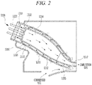
- FIG. 2 is a cross-sectional view of a combustor of the gas turbine according to an embodiment of the system.
- the gas turbine 1000 includes a compressor 1100, a combustor 1200, and a turbine 1300.
- the combustor 1200 includes a fuel nozzle assembly 1220, a combustion chamber 1210, a sleeve 1211, and an end plate 1213.
- Reference number 1110 denotes a compressor blade.
- the combustion chamber 1210 is a space that is formed inside a combustion liner 1212 and a transition piece 1217.
- the sleeve 1211 surrounds the combustion liner 1212 and extends in one direction.
- the combustion liner 1212 is formed inside the sleeve 1211 so as to extend in the direction in which the sleeve 1211 extends.
- the combustion liner 1212 is disposed so as to be spaced a predetermined distance apart from the sleeve 1211, and a flow passage 1215 having a ring-shaped cross-section is formed between the sleeve 1211 and the combustion liner 1212.
- the end plate 1213 is coupled to an end portion of the sleeve 1211 so as to seal the sleeve 1211.
- the end plate 1213 may be coupled to a manifold, a related valve, and the like, which are provided for the supply of fuel to a fuel nozzle 1221.
- the fuel nozzle assembly 1220 is connected to the combustion liner 1212.
- the fuel nozzle assembly 1220 includes a plurality of fuel nozzles.
- Each of the fuel nozzles 1221 is supported at one end thereof by the end plate 1213.
- the air compressed in the compressor 1100 is introduced into the flow passage 1215 through a cooling hole 1216 formed in the sleeve 1211 and flows through the flow passage 1215 while cooling the combustion liner 1212.
- the compressed air which has flowed through the flow passage 1215, reaches the end plate 1213 disposed at the end portion of the sleeve 1211.
- the direction in which the compressed air flows is changed by the end plate 1213, and the compressed air is introduced into the inlet port of the fuel nozzle assembly 1220.
- the compressed air introduced in this way is mixed with fuel, which is injected through the fuel nozzles 1221, and the mixture moves to the combustion chamber 1210, which is formed inside the combustion liner 1212 and the transition piece 1217.
- the mixture is ignited by an ignition plug (not illustrated) and is combusted in the combustion chamber 1210. Subsequently, the combusted gas is exhausted to the turbine 1300 and rotates the turbine 1300.
- FIG. 3 is a view showing the influence of a cross-flow on a jet flow inside a flow passage.
- compressed air introduced into the flow passage 1215 through a cooling hole 1216 applies impingement cooling to the surfaces of the combustion liner 1212 and the transition piece 1217 in the diagonal direction, not in the direction perpendicular thereto, due to compressed air flowing through the flow passage 1215 in the transverse direction (hereinafter, referred to as a "cross-flow").
- the angle at which the impingement cooling is implemented in the diagonal direction is gradually increased toward the end portion of a sleeve 1211, at which an end plate 1213 is provided, by airflow momentum, which is gradually increased toward the end portion of the sleeve 1211.
- Embodiments of the system provide a combustor that is capable of improving impingement cooling performance by reducing the influence of a cross-flow on a jet flow, as illustrated in FIG. 3 .
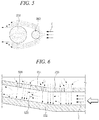
- FIG. 4 is a partial side-sectional view illustrating a portion of a combustor according to an embodiment of the system
- FIG. 5 is a plan view of a portion of FIG. 4 , which illustrates the flow of compressed air in the flow passage.
- the combustor according to an embodiment of the system includes a sleeve 1211, a combustion liner 1212, a cooling hole 1216, and a first auxiliary hole 2100.
- a combustion chamber 1210 is an energy-generating element, which drives a turbine by combusting a mixture, in which fuel and compressed air are premixed, and by converting high-temperature gas into kinetic energy.
- the sleeve 1211 surrounds the combustion liner 1212 and the transition piece 1217 while being spaced apart therefrom.
- the cooling hole 1216 may be formed in a portion of the sleeve that surrounds the combustion liner 1212, and may also be formed in a portion of the sleeve that surrounds the transition piece 1217.
- the first auxiliary hole 2100 is formed upstream of the cooling hole 1216 on the basis of the airflow direction.
- the upstream side of the cooling hole refers to a region in which compressed air introduced into the flow passage 1215 through the first auxiliary hole 2100 impinges with a cross-flow earlier than compressed air introduced into the flow passage 1215 through the cooling hole 1216.
- the cross-flow C flowing through the flow passage 1215 primarily impinges with the compressed air introduced into the flow passage 1215 through the first auxiliary hole 2100, and thus the cross-flow is diverted from the impingement point so as to avoid impinging with the compressed air introduced into the flow passage 1215 through the cooling hole 1216.
- the compressed air introduced into the flow passage 1215 through the first auxiliary hole 2100 serves as an air column, which prevents the compressed air introduced into the flow passage 1215 through the cooling hole 1216 from being affected by the cross-flow.
- the jet flow Since the compressed air introduced through the cooling hole 1216 (the jet flow) is affected less by the cross-flow due to the air-column effect exhibited by the compressed air introduced through the first auxiliary hole 2100, the jet flow impinges with the surfaces of the combustion liner 1212 and the transition piece 1217 in a direction substantially perpendicular thereto. Needless to say, because it is difficult to completely exclude the influence of the cross-flow, the jet flow may perform impingement in the diagonal direction to a certain extent. However, the impingement angle is closer to a right angle than that in the prior art. Therefore, impingement cooling efficiency may be improved, and the surface temperature of the combustion liner 1212 and the transition piece 1217 may be maintained relatively low. As a result, it is possible to prevent deterioration in the strength of the combustion liner 1212 and the transition piece 1217.
- the diameter of the cooling hole 1216 is D
- the cooling hole 1216 and the first auxiliary hole 2100 be spaced apart from each other such that the straight-line distance therebetween is set to a value that is equal to or less than the diameter D of the cooling hole. If the straight-line distance between the cooling hole 1216 and the first auxiliary hole 2100 exceeds the value of the diameter D of the cooling hole, the air-column effect exhibited by the compressed air introduced through the first auxiliary hole 2100 may be degraded, and thus the cross-flow may have an influence on the jet flow.
- FIG. 6 is a partial side-sectional view illustrating a portion of a combustor according to an embodiment of the system
- FIG. 7 is a plan view of a portion of FIG. 6 , which illustrates the flow of compressed air in a flow passage.
- the combustor according to Fig. 6 of the system includes a second auxiliary hole 2200, which is formed downstream of the cooling hole 1216 in airflow direction, instead of the first auxiliary hole 2100 formed upstream of the cooling hole 1216 in the combustor.
- the other components such as a sleeve 1211, a combustion liner 1212, a flow passage 1215, a cooling hole 1216, and a transition piece 1217, of the combustor according to an embodiment are substantially the same as those of the combustor described above, and therefore a duplicate explanation thereof will be omitted.
- the second auxiliary hole 2200 is formed downstream of the cooling hole 1216 on the basis of the airflow direction.
- the downstream side of the cooling hole refers to a region in which the compressed air introduced into the flow passage 1215 through the cooling hole 1216 primarily impinges with the cross-flow and the compressed air introduced into the flow passage 1215 through the second auxiliary hole 2200 secondarily impinges with the cross-flow.
- the cross-flow flowing through the flow passage 1215 primarily impinges with the compressed air introduced through the cooling hole 1216, and becomes turbulent due to the air column formed by jet flow. Subsequently, the turbulence generated in this way is mitigated by the compressed air introduced through the second auxiliary hole 2200, which serves to maintain the momentum of the compressed air introduced through the cooling hole 1216.
- impingement cooling efficiency may be improved, and the surface temperature of the combustion liner 1212 and the transition piece 1217 may be maintained relatively low. As a result, it is possible to prevent deterioration in the strength of the combustion liner 1212 and the transition piece 1217.
- the diameter of the second auxiliary hole 2200 and the straight-line distance between the cooling hole 1216 and the second auxiliary hole 2200 may be set to predetermined values in the same way as in the above-described embodiment.
- FIG. 8 is a partial side-sectional view illustrating a portion of a combustor according to an embodiment of the system
- FIG. 9 is a plan view of a portion of FIG. 8 , which illustrates the flow of compressed air in a flow passage.
- the combustor according to an embodiment of the system is a combination of the above-described combustors.
- a first auxiliary hole 2100 is formed upstream of a cooling hole 1216, and a second auxiliary hole 2200 is formed downstream of the cooling hole 1216.
- the diameter of the first auxiliary hole 2100, the straight-line distance between the cooling hole 1216 and the first auxiliary hole 2100, the diameter of the second auxiliary hole 2200 and the straight-line distance between the cooling hole 1216 and the second auxiliary hole 2200 may be set to predetermined values in the same way as in the above-described system.
- the compressed air introduced through the first auxiliary hole 2100 impinges with the cross-flow flowing through a flow passage 1215 and serves as an air column, by which the cross-flow is diverted from the impingement point, and the turbulence, which is generated by impingement between the compressed air introduced through the first auxiliary hole 2100 or the cooling hole 1216 and the cross-flow, is mitigated by the compressed air introduced through the second auxiliary hole 2200, thereby maintaining the momentum of the introduced compressed air.
- impingement cooling may be more efficiently applied to the combustion liner 1212 and the transition piece 1217, and the surface temperature of the combustion liner 1212 and the transition piece 1217 may be maintained relatively low. As a result, it is possible to prevent deterioration in the strength of the combustion liner 1212 and the transition piece 1217.
- FIG. 10 is a plan view illustrating various examples of combustors according to embodiments of the system.
- the combustors according to embodiments of the system are not limited to a configuration in which the cooling hole 1216 and the first auxiliary hole 2100 are spaced apart from each other or in which the cooling hole 1216 and the second auxiliary hole 2200 are spaced apart from each other, and may be configured such that at least a portion of the first auxiliary hole 2100 and/or the second auxiliary hole 2200 overlaps the cooling hole 1216.
- the air-column effect exhibited by the first auxiliary hole 2100 or the air-column momentum maintenance effect exhibited by the second auxiliary hole 2200 may be obtained, thereby further improving impingement cooling efficiency compared to the prior art.
- the jet flow is affected less by the cross-flow due to the air-column effect exhibited by the compressed air introduced through the first auxiliary hole, the jet flow impinges with the surfaces of the combustion liner and the transition piece in the direction substantially perpendicular thereto. As a result, impingement cooling efficiency is improved.
Landscapes
- Engineering & Computer Science (AREA)
- Chemical & Material Sciences (AREA)
- Combustion & Propulsion (AREA)
- Mechanical Engineering (AREA)
- General Engineering & Computer Science (AREA)
- Turbine Rotor Nozzle Sealing (AREA)
- Gas Burners (AREA)
Abstract
Description
- This application claims priority to and the benefit of Korean Patent Application No.
10-2017-0057558 - The system relates to a combustor, a gas turbine including the same, and a method of distributing compressed air in the combustor.
- A turbine is a mechanical device that extracts an impulsive/or repulsive force from the flow of a compressive fluid or uses compressed air and fuel to produce heat release energy with huge fluid momentum by burning fuel and air mixture in combustion chamber and converts the same into a rotational force. If steam is used as the fluid, it is called a steam turbine, and if combustion gas is used as the fluid, it is called a gas turbine.
- The thermal cycle of the gas turbine is referred to as the Brayton cycle, and the gas turbine comprises a compressor, a combustor, and a turbine. According to the operating principle of the gas turbine, air is sucked from the atmosphere and compressed by the compressor, the compressed air is supplied to the combustor wherein air and fuel are mixed and burnt to produce high-temperature and high-pressure combustion gas for driving the turbine, and exhaust gas is emitted to the atmosphere. As such, the thermal cycle of the gas turbine includes four processes, namely compression, combustion, expansion, and heat rejection.
- The compressor of the gas turbine serves to suck air from the atmosphere and to supply the air for combustion to the combustor. The pressure and the air temperature in the compressor are increased via adiabatic compression.
- The combustor mixes the compressed air introduced thereinto with fuel and combusts the mixture to produce combustion gas having high energy. Through an isobaric combustion process, the temperature of the combustion gas is raised up to the temperature limit of the combustor and the turbine.
- The high-temperature and high-pressure combustion gas produced from the combustor is expanded in the turbine, and the expanded gas provides an impulsive or repulsive force to the rotary blades of the turbine, thus generating mechanical energy. Some of the mechanical energy generated in the turbine is supplied to the compressor as energy for compressing air, and the remainder is used to drive an electric generator in order to produce power.
- It is important in terms of improvement of durability of the combustor to cool a combustor liner and a transition piece, which are exposed to high-temperature and high-pressure combustion gas. The combustor liner and the transition piece are surrounded by a flow sleeve. Air is introduced through a cooling hole formed in the flow sleeve and impinges with the surfaces of the combustor liner and the transition piece in the direction perpendicular thereto, thereby cooling the combustor liner and the transition piece.
- However, a jet flow introduced through the cooling hole applies impingement cooling to the surfaces of the combustor liner and the transition piece in the diagonal direction, not in the direction perpendicular thereto, due to a cross-flow, which flows through a flow passage, defined by the combustor liner, the transition piece and the flow sleeve surrounding the combustor liner and the transition piece, in the transverse direction. In addition, the angle at which the impingement cooling is implemented in the diagonal direction is gradually increased toward the upstream side in the airflow direction by airflow momentum, which is gradually increased toward the upstream side. Therefore, impingement cooling efficiency is low, and the temperature of the outer surfaces of the combustor liner and the transition piece becomes high, and consequently the strength of the combustor liner and the transition piece is deteriorated. As a result, the lifespan of the combustor liner and the transition piece is shortened, and thus these components need to be frequently replaced.
- [Related Art Document] Korean Patent Registration No.
10-0013120 - Therefore, the system has been made in view of the above problems, and it is an object of the system to provide a combustor capable of improving impingement cooling performance by reducing the influence of a cross-flow on a jet flow, a gas turbine including the same, and a method of distributing compressed air in the combustor.
- In accordance with an aspect of the system, the above and other objects can be accomplished by the provision of a combustor including a combustion liner constituting a combustion chamber and disposed on the upstream side in the combustion gas flow direction, a transition piece constituting the combustion chamber and disposed on the downstream side in the combustion gas flow direction, and a sleeve surrounding the combustion liner and the transition piece while being spaced apart therefrom. A flow passage is formed between the combustion liner and the sleeve and between the transition piece and the sleeve, and compressed air discharged from a compressor is introduced into the flow passage through a cooling hole formed in the sleeve. A first auxiliary hole is formed upstream of the cooling hole in the airflow direction. Compressed air discharged from the compressor is introduced into the flow passage through the first auxiliary hole, impinges with compressed air flowing through the flow passage, and forms an air column.
- When the cooling hole has a diameter of a value of D, the first auxiliary hole may be formed to have a diameter of a value of 0.5D or less.
- The cooling hole and the first auxiliary hole may be spaced apart from each other such that the straight-line distance therebetween has a value that is equal to or less than the diameter (D) of the cooling hole.
- The combustor may further include a second auxiliary hole formed downstream of the cooling hole in the airflow direction. Compressed air discharged from the compressor may be introduced into the flow passage through the second auxiliary hole, may mitigate turbulence generated downstream of the cooling hole, and may maintain the momentum of the compressed air introduced through the cooling hole.
- When the cooling hole has a diameter of a value of D, the second auxiliary hole may be formed to have a diameter of a value of approximately 0.5D or less.
- The cooling hole and the second auxiliary hole may be spaced apart from each other such that the straight-line distance therebetween has a value that is equal to or less than the diameter (D) of the cooling hole.
- At least one of the first auxiliary hole or the second auxiliary hole may be formed such that at least a portion thereof overlaps the cooling hole.
- In accordance with another aspect of the system, there is provided a combustor including a combustion liner constituting a combustion chamber and disposed on the upstream side in the combustion gas flow direction, and a transition piece constituting the combustion chamber and disposed on the downstream side in the combustion gas flow direction. A flow passage is formed between the combustion liner and a sleeve and between the transition piece and the sleeve, and compressed air discharged from a compressor is introduced into the flow passage through a cooling hole formed in the sleeve. A second auxiliary hole is formed downstream of the cooling hole in the airflow direction. Compressed air discharged from the compressor is introduced into the flow passage through the second auxiliary hole, mitigates turbulence generated downstream of the cooling hole, and maintains the momentum of the compressed air introduced through the cooling hole.
- When the cooling hole has a diameter of a value of D, the second auxiliary hole may be formed to have a diameter of a value of 0.5D or less.
- The cooling hole and the second auxiliary hole may be spaced apart from each other such that the straight-line distance therebetween has a value that is equal to or less than the diameter (D) of the cooling hole.
- The second auxiliary hole may be formed such that at least a portion thereof overlaps the cooling hole.
- In accordance with a further aspect of the system, there is provided a gas turbine including a compressor configured to compress air, a combustor configured to receive compressed air from the compressor, to form a mixture by mixing the compressed air with fuel, and to combust the mixture, and a turbine configured to be rotated by combustion gas discharged from the combustor to produce power.
- The combustor includes a combustion liner constituting a combustion chamber and disposed on the upstream side in the combustion gas flow direction, a transition piece constituting the combustion chamber and disposed on the downstream side in the combustion gas flow direction, and a sleeve surrounding the combustion liner and the transition piece while being spaced apart therefrom. A flow passage is formed between the combustion liner and the sleeve and between the transition piece and the sleeve, and compressed air discharged from the compressor is introduced into the flow passage through a cooling hole formed in the sleeve. A first auxiliary hole is formed upstream of the cooling hole in the airflow direction. Compressed air discharged from the compressor is introduced into the flow passage through the first auxiliary hole, impinges with compressed air flowing through the flow passage, and forms an air column.
- The combustor may further include a second auxiliary hole formed downstream of the cooling hole in the airflow direction. Compressed air discharged from the compressor may be introduced into the flow passage through the second auxiliary hole, may mitigate turbulence generated downstream of the cooling hole, and may maintain the momentum of the compressed air introduced through the cooling hole.
- In accordance with a further aspect of the system, there is provided a method of distributing compressed air in a combustor configured to receive compressed air from a compressor, to form a mixture by mixing the compressed air with fuel, and to combust the mixture, the method including forming a cross-flow by allowing compressed air to be introduced into a flow passage, formed between a combustion liner and a sleeve and between a transition piece and the sleeve, through a cooling hole and to flow through the flow passage, and forming an air column by allowing compressed air introduced into the flow passage through a first auxiliary hole, formed upstream of the cooling hole in the airflow direction, to impinge with the cross-flow.
- The method may further include mitigating turbulence generated downstream of the cooling hole in the airflow direction and maintaining the momentum of the compressed air introduced through the cooling hole by allowing compressed air to be introduced into the flow passage through a second auxiliary hole formed downstream of the cooling hole in the airflow direction.
- In accordance with a further aspect of the system, there is provided a method of distributing compressed air in a combustor, the method including mitigating turbulence generated downstream of a cooling hole in the airflow direction and maintaining the momentum of the compressed air introduced through the cooling hole by allowing compressed air to be introduced into a flow passage through a second auxiliary hole, without forming an air column.
- The above and other objects, features and other advantages of the system will be more clearly understood from the following detailed description taken in conjunction with the accompanying drawings, in which:
-
FIG. 1 is a view illustrating the interior of a gas turbine according to an embodiment of the system; -
FIG. 2 is a cross-sectional view of a combustor of the gas turbine according to an embodiment of the system; -
FIG. 3 is a view showing the influence of a cross-flow on a jet flow inside a flow passage; -
FIG. 4 is a partial side-sectional view illustrating a portion of a combustor according to an embodiment of the system; -
FIG. 5 is a plan view of a portion ofFIG. 4 , which illustrates the flow of compressed air in the flow passage; -
FIG. 6 is a partial side-sectional view illustrating a portion of a combustor according to an embodiment of the system; -
FIG. 7 is a plan view of a portion ofFIG. 6 , which illustrates the flow of compressed air in the flow passage; -
FIG. 8 is a partial side-sectional view illustrating a portion of a combustor according to an embodiment of the system; -
FIG. 9 is a plan view of a portion ofFIG. 8 , which illustrates the flow of compressed air in the flow passage; and -
FIG. 10 is a plan view illustrating various examples of an embodiment of the system ofFig. 8 . - Since embodiments of the system can be variously modified in many different forms, reference will now be made in detail to specific embodiments of the system. It is to be understood that the present description is not intended to limit the system to those specific embodiments and that the system is intended to cover not only the specific embodiments but also various alternatives, modifications, equivalents and other embodiments that may be included within the scope of the system as defined by the appended claims.
- The terminology used herein is for the purpose of describing particular embodiments only and is not intended to be limiting. As used herein, the singular forms are intended to include the plural forms as well, unless the context clearly indicates otherwise. It will be further understood that the terms "comprise", "include", "have", etc., when used in this specification, specify the presence of stated features, integers, steps, operations, elements, components, and/or combinations thereof, but do not preclude the presence or addition of one or more other features, integers, steps, operations, elements, components, and/or combinations thereof.
- Hereinafter, embodiments of the system will be described in detail with reference to the accompanying drawings. In the drawings, the same or similar elements are denoted by the same reference numerals even though they are depicted in different drawings. In the following description, a detailed description of known functions and configurations incorporated herein will be omitted when it may make the subject matter of the system rather unclear. In the drawings, elements may be exaggerated in size, omitted or schematically illustrated for convenience in description and clarity.
-
FIG. 1 is a view illustrating the interior of a gas turbine according to an embodiment of the system, andFIG. 2 is a cross-sectional view of a combustor of the gas turbine according to an embodiment of the system. - As illustrated in
FIGs. 1 and2 , thegas turbine 1000 according to an embodiment of the system includes acompressor 1100, acombustor 1200, and aturbine 1300. Thecombustor 1200 includes afuel nozzle assembly 1220, acombustion chamber 1210, asleeve 1211, and anend plate 1213.Reference number 1110 denotes a compressor blade. - The
combustion chamber 1210 is a space that is formed inside acombustion liner 1212 and atransition piece 1217. Thesleeve 1211 surrounds thecombustion liner 1212 and extends in one direction. Thecombustion liner 1212 is formed inside thesleeve 1211 so as to extend in the direction in which thesleeve 1211 extends. Thecombustion liner 1212 is disposed so as to be spaced a predetermined distance apart from thesleeve 1211, and aflow passage 1215 having a ring-shaped cross-section is formed between thesleeve 1211 and thecombustion liner 1212. Theend plate 1213 is coupled to an end portion of thesleeve 1211 so as to seal thesleeve 1211. Theend plate 1213 may be coupled to a manifold, a related valve, and the like, which are provided for the supply of fuel to afuel nozzle 1221. - The
fuel nozzle assembly 1220 is connected to thecombustion liner 1212. Thefuel nozzle assembly 1220 includes a plurality of fuel nozzles. - Compressed air and fuel are mixed with each other in each of the
fuel nozzles 1221. Each of thefuel nozzles 1221 is supported at one end thereof by theend plate 1213. - The air compressed in the
compressor 1100 is introduced into theflow passage 1215 through acooling hole 1216 formed in thesleeve 1211 and flows through theflow passage 1215 while cooling thecombustion liner 1212. The compressed air, which has flowed through theflow passage 1215, reaches theend plate 1213 disposed at the end portion of thesleeve 1211. The direction in which the compressed air flows is changed by theend plate 1213, and the compressed air is introduced into the inlet port of thefuel nozzle assembly 1220. The compressed air introduced in this way is mixed with fuel, which is injected through thefuel nozzles 1221, and the mixture moves to thecombustion chamber 1210, which is formed inside thecombustion liner 1212 and thetransition piece 1217. The mixture is ignited by an ignition plug (not illustrated) and is combusted in thecombustion chamber 1210. Subsequently, the combusted gas is exhausted to theturbine 1300 and rotates theturbine 1300. - Impingement cooling, which is applied to a
combustion liner 1212 and atransition piece 1217 in a conventional combustor, will now be described with reference toFIG. 3. FIG. 3 is a view showing the influence of a cross-flow on a jet flow inside a flow passage. - As illustrated in
FIG. 3 , compressed air introduced into theflow passage 1215 through a cooling hole 1216 (hereinafter, referred to as a "jet flow") applies impingement cooling to the surfaces of thecombustion liner 1212 and thetransition piece 1217 in the diagonal direction, not in the direction perpendicular thereto, due to compressed air flowing through theflow passage 1215 in the transverse direction (hereinafter, referred to as a "cross-flow"). In addition, the angle at which the impingement cooling is implemented in the diagonal direction is gradually increased toward the end portion of asleeve 1211, at which anend plate 1213 is provided, by airflow momentum, which is gradually increased toward the end portion of thesleeve 1211. - Therefore, impingement cooling efficiency is low, and thus the temperature of the outer surfaces of the
combustion liner 1212 and thetransition piece 1217 becomes high. Consequently, the strength of thecombustion liner 1212 and thetransition piece 1217 is deteriorated. - Embodiments of the system provide a combustor that is capable of improving impingement cooling performance by reducing the influence of a cross-flow on a jet flow, as illustrated in
FIG. 3 . -
FIG. 4 is a partial side-sectional view illustrating a portion of a combustor according to an embodiment of the system, andFIG. 5 is a plan view of a portion ofFIG. 4 , which illustrates the flow of compressed air in the flow passage. - Referring to
FIG. 4 , the combustor according to an embodiment of the system includes asleeve 1211, acombustion liner 1212, acooling hole 1216, and a firstauxiliary hole 2100. - A
combustion chamber 1210 is an energy-generating element, which drives a turbine by combusting a mixture, in which fuel and compressed air are premixed, and by converting high-temperature gas into kinetic energy. Thesleeve 1211 surrounds thecombustion liner 1212 and thetransition piece 1217 while being spaced apart therefrom. Aflow passage 1215, through which compressed air introduced thereinto through thecooling hole 1216 flows along thecombustion liner 1212 and thetransition piece 1217, is formed between thecombustion liner 1212 and thesleeve 1211 and between thetransition piece 1217 and thesleeve 1211. Thecooling hole 1216 may be formed in a portion of the sleeve that surrounds thecombustion liner 1212, and may also be formed in a portion of the sleeve that surrounds thetransition piece 1217. - The first
auxiliary hole 2100 is formed upstream of thecooling hole 1216 on the basis of the airflow direction. Here, the upstream side of the cooling hole refers to a region in which compressed air introduced into theflow passage 1215 through the firstauxiliary hole 2100 impinges with a cross-flow earlier than compressed air introduced into theflow passage 1215 through thecooling hole 1216. - As illustrated in
FIG. 5 , the cross-flow C flowing through theflow passage 1215 primarily impinges with the compressed air introduced into theflow passage 1215 through the firstauxiliary hole 2100, and thus the cross-flow is diverted from the impingement point so as to avoid impinging with the compressed air introduced into theflow passage 1215 through thecooling hole 1216. In other words, the compressed air introduced into theflow passage 1215 through the firstauxiliary hole 2100 serves as an air column, which prevents the compressed air introduced into theflow passage 1215 through thecooling hole 1216 from being affected by the cross-flow. - Since the compressed air introduced through the cooling hole 1216 (the jet flow) is affected less by the cross-flow due to the air-column effect exhibited by the compressed air introduced through the first
auxiliary hole 2100, the jet flow impinges with the surfaces of thecombustion liner 1212 and thetransition piece 1217 in a direction substantially perpendicular thereto. Needless to say, because it is difficult to completely exclude the influence of the cross-flow, the jet flow may perform impingement in the diagonal direction to a certain extent. However, the impingement angle is closer to a right angle than that in the prior art. Therefore, impingement cooling efficiency may be improved, and the surface temperature of thecombustion liner 1212 and thetransition piece 1217 may be maintained relatively low. As a result, it is possible to prevent deterioration in the strength of thecombustion liner 1212 and thetransition piece 1217. - Hereinafter, the above-described combustor according to an embodiment of the system will be described in more detail. When the diameter of the
cooling hole 1216 is D, it is desirable that the diameter of the firstauxiliary hole 2100 be set to 0.5D or less. If the diameter of the firstauxiliary hole 2100 exceeds 0.5D, the function of the firstauxiliary hole 2100 is not actually discriminated from the function of thecooling hole 1216. That is, this may be equivalent to the configuration in which another cooling hole is added, and such a configuration poses a problem in that the overall momentum of the jet flow is weakened, and thus cooling efficiency is deteriorated. - In addition, it is desirable that the
cooling hole 1216 and the firstauxiliary hole 2100 be spaced apart from each other such that the straight-line distance therebetween is set to a value that is equal to or less than the diameter D of the cooling hole. If the straight-line distance between thecooling hole 1216 and the firstauxiliary hole 2100 exceeds the value of the diameter D of the cooling hole, the air-column effect exhibited by the compressed air introduced through the firstauxiliary hole 2100 may be degraded, and thus the cross-flow may have an influence on the jet flow. -
FIG. 6 is a partial side-sectional view illustrating a portion of a combustor according to an embodiment of the system, andFIG. 7 is a plan view of a portion ofFIG. 6 , which illustrates the flow of compressed air in a flow passage. - The combustor according to
Fig. 6 of the system includes a secondauxiliary hole 2200, which is formed downstream of thecooling hole 1216 in airflow direction, instead of the firstauxiliary hole 2100 formed upstream of thecooling hole 1216 in the combustor. However, the other components, such as asleeve 1211, acombustion liner 1212, aflow passage 1215, acooling hole 1216, and atransition piece 1217, of the combustor according to an embodiment are substantially the same as those of the combustor described above, and therefore a duplicate explanation thereof will be omitted. - The second
auxiliary hole 2200 is formed downstream of thecooling hole 1216 on the basis of the airflow direction. Here, the downstream side of the cooling hole refers to a region in which the compressed air introduced into theflow passage 1215 through thecooling hole 1216 primarily impinges with the cross-flow and the compressed air introduced into theflow passage 1215 through the secondauxiliary hole 2200 secondarily impinges with the cross-flow. - As illustrated in
FIG. 7 , the cross-flow flowing through theflow passage 1215 primarily impinges with the compressed air introduced through thecooling hole 1216, and becomes turbulent due to the air column formed by jet flow. Subsequently, the turbulence generated in this way is mitigated by the compressed air introduced through the secondauxiliary hole 2200, which serves to maintain the momentum of the compressed air introduced through thecooling hole 1216. - Therefore, impingement cooling efficiency may be improved, and the surface temperature of the
combustion liner 1212 and thetransition piece 1217 may be maintained relatively low. As a result, it is possible to prevent deterioration in the strength of thecombustion liner 1212 and thetransition piece 1217. - The diameter of the second
auxiliary hole 2200 and the straight-line distance between thecooling hole 1216 and the secondauxiliary hole 2200 may be set to predetermined values in the same way as in the above-described embodiment. -
FIG. 8 is a partial side-sectional view illustrating a portion of a combustor according to an embodiment of the system, andFIG. 9 is a plan view of a portion ofFIG. 8 , which illustrates the flow of compressed air in a flow passage. - The combustor according to an embodiment of the system is a combination of the above-described combustors. A first
auxiliary hole 2100 is formed upstream of acooling hole 1216, and a secondauxiliary hole 2200 is formed downstream of thecooling hole 1216. - The diameter of the first
auxiliary hole 2100, the straight-line distance between thecooling hole 1216 and the firstauxiliary hole 2100, the diameter of the secondauxiliary hole 2200 and the straight-line distance between thecooling hole 1216 and the secondauxiliary hole 2200 may be set to predetermined values in the same way as in the above-described system. - As illustrated in
FIG. 9 , according to the combustor of an embodiment, the compressed air introduced through the firstauxiliary hole 2100 impinges with the cross-flow flowing through aflow passage 1215 and serves as an air column, by which the cross-flow is diverted from the impingement point, and the turbulence, which is generated by impingement between the compressed air introduced through the firstauxiliary hole 2100 or thecooling hole 1216 and the cross-flow, is mitigated by the compressed air introduced through the secondauxiliary hole 2200, thereby maintaining the momentum of the introduced compressed air. - Therefore, impingement cooling may be more efficiently applied to the
combustion liner 1212 and thetransition piece 1217, and the surface temperature of thecombustion liner 1212 and thetransition piece 1217 may be maintained relatively low. As a result, it is possible to prevent deterioration in the strength of thecombustion liner 1212 and thetransition piece 1217. -
FIG. 10 is a plan view illustrating various examples of combustors according to embodiments of the system. - As illustrated in
FIG. 10 , the combustors according to embodiments of the system are not limited to a configuration in which thecooling hole 1216 and the firstauxiliary hole 2100 are spaced apart from each other or in which thecooling hole 1216 and the secondauxiliary hole 2200 are spaced apart from each other, and may be configured such that at least a portion of the firstauxiliary hole 2100 and/or the secondauxiliary hole 2200 overlaps thecooling hole 1216. - In the case in which a portion of the first
auxiliary hole 2100 and/or the secondauxiliary hole 2200 overlaps thecooling hole 1216, like the above-described embodiments, the air-column effect exhibited by the firstauxiliary hole 2100 or the air-column momentum maintenance effect exhibited by the secondauxiliary hole 2200 may be obtained, thereby further improving impingement cooling efficiency compared to the prior art. - As is apparent from the above description, according to an embodiment of the system, since the jet flow is affected less by the cross-flow due to the air-column effect exhibited by the compressed air introduced through the first auxiliary hole, the jet flow impinges with the surfaces of the combustion liner and the transition piece in the direction substantially perpendicular thereto. As a result, impingement cooling efficiency is improved.
- In addition, since the turbulence generated by impingement between the cross-flow and the jet flow is mitigated and the momentum of the jet flow is maintained by the compressed air introduced through the second auxiliary hole, it is possible to improve impingement cooling efficiency.
- Although the embodiments of the system have been disclosed for illustrative purposes, those skilled in the art will appreciate that various modifications, additions and substitutions are possible, without departing from the scope of the system as disclosed in the accompanying claims.
Claims (15)
- A combustor comprising:a combustion liner (1212) constituting a combustion chamber (1210) and disposed on an upstream side in a combustion gas flow direction;a transition piece (1217) constituting the combustion chamber (1210) and disposed on a downstream side in the combustion gas flow direction;a sleeve (1211) surrounding the combustion liner(1212) and the transition piece (1217) while being spaced apart therefrom;a flow passage (1215) formed between the combustion liner (1212) and the sleeve (1211) and between the transition piece (1217) and the sleeve (1211);a cooling hole (1216) formed in the sleeve (1211) to introduce compressed air discharged from a compressor (1100) into the flow passage (1215); andat least one of a first auxiliary hole (2100) and a second auxiliary hole(2200), wherein the first auxiliary hole (2100) is formed upstream of the cooling hole (1216) in an airflow direction, the second auxiliary hole (2200) is formed downstream of the cooling hole (1216) in an airflow direction.
- The combustor according to claim 1, wherein compressed air discharged from the compressor (1100) is introduced into the flow passage (1215) through the first auxiliary hole (2100), impinges with compressed air flowing through the flow passage (1215), and forms an air column.
- The combustor according to claim 1 or claim 2, wherein compressed air discharged from the compressor (1100) is introduced into the flow passage (1215) through the second auxiliary hole (2200), mitigates turbulence generated downstream of the cooling hole (1216), and maintains momentum of compressed air introduced through the cooling hole (1216).
- The combustor according to any one of the claims 1 to 3, wherein, when the cooling hole (1216) has a diameter of a value of D, the first auxiliary hole (2100) is formed to have a diameter of a value of 0.5D or less.
- The combustor according to any one of the claims 1 to 4, wherein the cooling hole (1216) and the first auxiliary hole (2100) are spaced apart from each other such that a straight-line distance therebetween has a value that is equal to or less than a diameter (D) of the cooling hole (1216).
- The combustor according to any one of the claims 1 to 5, wherein, when the cooling hole (1216) has a diameter of a value of D, the second auxiliary hole (2200) is formed to have a diameter of a value of 0.5D or less.
- The combustor according to any one of the claims 1 to 6, wherein the cooling hole (1216) and the second auxiliary hole (2200) are spaced apart from each other such that a straight-line distance therebetween has a value that is equal to or less than a diameter (D) of the cooling hole (1216).
- The combustor according to any one of the claims 1 to 7, wherein at least one of the first auxiliary hole(2100) or the second auxiliary hole (2200) is formed such that at least a portion thereof overlaps the cooling hole (1216).
- A method of distributing compressed air in a combustor configured to receive compressed air from a compressor (1100), to form a mixture by mixing the compressed air with fuel, and to combust the mixture, the method comprising:forming a cross-flow by allowing compressed air to be introduced into a flow passage (1215), formed between a combustion liner (1212) and a sleeve (1211) and between a transition piece (1217) and the sleeve (1211), through a cooling hole (1216) and to flow through the flow passage(1215); andintroducing the compressed air into the flow passage (1215) through at least one of a first auxiliary hole (2100) formed in upstream of the cooling hole (1216) in an airflow direction and a second auxiliary hole (2200) formed in downstream of the cooling hole (1216) in an airflow direction.
- The method according to claim 9, further comprising: forming an air column by allowing compressed air introduced into the flow passage (1215) through a first auxiliary hole (2100), formed upstream of the cooling hole (1216) in an airflow direction, to impinge with the cross-flow.
- The method according to claim 9 or claim 10, further comprising: mitigating turbulence generated downstream of the cooling hole (1216) in an airflow direction and maintaining momentum of compressed air introduced through the cooling hole(1216) by allowing compressed air to be introduced into the flow passage (1215) through a second auxiliary hole (2200) formed downstream of the cooling hole (1216) in the airflow direction.
- The method according to any one of the claims 9 to 11, wherein, when the cooling hole (1216) has a diameter of a value of D, the first auxiliary hole (2100) is formed to have a diameter of a value of 0.5D or less,
and wherein the cooling hole (1216) and the first auxiliary hole (2100) are spaced apart from each other such that a straight-line distance therebetween has a value that is equal to or less than a diameter (D) of the cooling hole (1216). - The method according to any one of the claims 9 to 12, wherein, when the cooling hole(1216) has a diameter of a value of D, the second auxiliary hole (2200) is formed to have a diameter of a value of 0.5D or less,
and wherein the cooling hole (1216) and the second auxiliary hole (2200) are spaced apart from each other such that a straight-line distance therebetween has a value that is equal to or less than a diameter (D) of the cooling hole (1216). - The method according to any one of the claims 9 to 13, wherein the first auxiliary hole (2100) is formed such that at least a portion thereof overlaps the cooling hole (1216).
- The method according to any one of the claims 9 to 14, wherein the second auxiliary hole (2200) is formed such that at least a portion thereof overlaps the cooling hole (1216).
Applications Claiming Priority (1)
| Application Number | Priority Date | Filing Date | Title |
|---|---|---|---|
| KR1020170057558A KR101906051B1 (en) | 2017-05-08 | 2017-05-08 | combustor and gas turbine comprising it and method of distributing compressed air using it |
Publications (2)
| Publication Number | Publication Date |
|---|---|
| EP3401601A1 true EP3401601A1 (en) | 2018-11-14 |
| EP3401601B1 EP3401601B1 (en) | 2021-03-31 |
Family
ID=62044518
Family Applications (1)
| Application Number | Title | Priority Date | Filing Date |
|---|---|---|---|
| EP18168368.1A Active EP3401601B1 (en) | 2017-05-08 | 2018-04-20 | Combustor and method of distributing compressed air in a combustor |
Country Status (4)
| Country | Link |
|---|---|
| US (1) | US11209161B2 (en) |
| EP (1) | EP3401601B1 (en) |
| KR (1) | KR101906051B1 (en) |
| CN (1) | CN108869046B (en) |
Cited By (1)
| Publication number | Priority date | Publication date | Assignee | Title |
|---|---|---|---|---|
| CN113530707A (en) * | 2021-08-16 | 2021-10-22 | 中国航发贵阳发动机设计研究所 | Spray pipe heat insulation layer structure and installation method |
Families Citing this family (6)
| Publication number | Priority date | Publication date | Assignee | Title |
|---|---|---|---|---|
| KR102097029B1 (en) | 2019-05-13 | 2020-04-03 | 두산중공업 주식회사 | Combustor and gas turbine including the same |
| US11959641B2 (en) * | 2020-01-31 | 2024-04-16 | Rtx Corporation | Combustor shell with shaped impingement holes |
| WO2022181694A1 (en) | 2021-02-25 | 2022-09-01 | 三菱パワー株式会社 | Cylinder for combustor, combustor, and gas turbine |
| CN115355537B (en) * | 2022-08-09 | 2023-09-22 | 中国航发沈阳发动机研究所 | Hydrogen fuel backflow type combustion chamber |
| CN115680781B (en) * | 2022-08-30 | 2024-05-03 | 中国航发四川燃气涡轮研究院 | Impeller exhaust device with cooling function |
| CN118090126B (en) * | 2024-04-28 | 2024-06-21 | 中国空气动力研究与发展中心超高速空气动力研究所 | Blending cooling device for high-temperature wind tunnel combustion heater and design method thereof |
Citations (3)
| Publication number | Priority date | Publication date | Assignee | Title |
|---|---|---|---|---|
| US20110107766A1 (en) * | 2009-11-11 | 2011-05-12 | Davis Jr Lewis Berkley | Combustor assembly for a turbine engine with enhanced cooling |
| US20110232299A1 (en) * | 2010-03-25 | 2011-09-29 | Sergey Aleksandrovich Stryapunin | Impingement structures for cooling systems |
| US20120234012A1 (en) * | 2011-03-15 | 2012-09-20 | General Electric Company | Impingement sleeve and methods for designing and forming impingement sleeve |
Family Cites Families (7)
| Publication number | Priority date | Publication date | Assignee | Title |
|---|---|---|---|---|
| DE10064264B4 (en) * | 2000-12-22 | 2017-03-23 | General Electric Technology Gmbh | Arrangement for cooling a component |
| US7669422B2 (en) * | 2006-07-26 | 2010-03-02 | General Electric Company | Combustor liner and method of fabricating same |
| US20100037620A1 (en) * | 2008-08-15 | 2010-02-18 | General Electric Company, Schenectady | Impingement and effusion cooled combustor component |
| US8677759B2 (en) * | 2009-01-06 | 2014-03-25 | General Electric Company | Ring cooling for a combustion liner and related method |
| US9249679B2 (en) * | 2011-03-15 | 2016-02-02 | General Electric Company | Impingement sleeve and methods for designing and forming impingement sleeve |
| US9249977B2 (en) | 2011-11-22 | 2016-02-02 | Mitsubishi Hitachi Power Systems, Ltd. | Combustor with acoustic liner |
| KR101355373B1 (en) | 2012-01-18 | 2014-01-27 | 주식회사 성일터빈 | Gas turbine combustor |
-
2017
- 2017-05-08 KR KR1020170057558A patent/KR101906051B1/en active Active
-
2018
- 2018-04-06 US US15/947,707 patent/US11209161B2/en active Active
- 2018-04-20 EP EP18168368.1A patent/EP3401601B1/en active Active
- 2018-04-27 CN CN201810391532.0A patent/CN108869046B/en active Active
Patent Citations (3)
| Publication number | Priority date | Publication date | Assignee | Title |
|---|---|---|---|---|
| US20110107766A1 (en) * | 2009-11-11 | 2011-05-12 | Davis Jr Lewis Berkley | Combustor assembly for a turbine engine with enhanced cooling |
| US20110232299A1 (en) * | 2010-03-25 | 2011-09-29 | Sergey Aleksandrovich Stryapunin | Impingement structures for cooling systems |
| US20120234012A1 (en) * | 2011-03-15 | 2012-09-20 | General Electric Company | Impingement sleeve and methods for designing and forming impingement sleeve |
Cited By (1)
| Publication number | Priority date | Publication date | Assignee | Title |
|---|---|---|---|---|
| CN113530707A (en) * | 2021-08-16 | 2021-10-22 | 中国航发贵阳发动机设计研究所 | Spray pipe heat insulation layer structure and installation method |
Also Published As
| Publication number | Publication date |
|---|---|
| KR101906051B1 (en) | 2018-10-08 |
| EP3401601B1 (en) | 2021-03-31 |
| US11209161B2 (en) | 2021-12-28 |
| CN108869046A (en) | 2018-11-23 |
| US20180320898A1 (en) | 2018-11-08 |
| CN108869046B (en) | 2021-06-01 |
Similar Documents
| Publication | Publication Date | Title |
|---|---|---|
| US11209161B2 (en) | Combustor, gas turbine including the same and method of distributing compressed air in combustor | |
| US10968755B2 (en) | Cooling structure for vane | |
| KR102066042B1 (en) | Combustor and gas turbine including the same | |
| EP4019841B1 (en) | Combustor nozzle for a gas turbine | |
| US20190107284A1 (en) | Combustor and gas turbine including the same | |
| KR102046457B1 (en) | Combustor and gas turbine including the same | |
| US11608985B2 (en) | Combustor and gas turbine including the same | |
| KR102049042B1 (en) | Fuel nozzle assembly, combustor and gas turbine having the same | |
| JP6001854B2 (en) | Combustor assembly for turbine engine and method for assembling the same | |
| US20170167381A1 (en) | Turbulators for improved cooling of gas turbine engine components | |
| KR101984396B1 (en) | Fuel nozzle, combustor and gas turbine having the same | |
| US10669860B2 (en) | Gas turbine blade | |
| KR102460672B1 (en) | Fuel nozzle, fuel nozzle module and combustor having the same | |
| KR102047369B1 (en) | Fuel nozzle, combustor and gas turbine having the same | |
| KR102456633B1 (en) | Trailing edge cooling structure of turbine blade | |
| KR102197130B1 (en) | Combustor and gas turbine including the same | |
| KR101877675B1 (en) | A transition piece assembly and a combustor and a gas turbine including the same | |
| KR20230140998A (en) | Duct assembly and combustor including the same | |
| KR102051988B1 (en) | Burner Having Flow Guide In Double Pipe Type Liner, And Gas Turbine Having The Same | |
| KR102817125B1 (en) | Airfoil and gas turbine comprising it | |
| KR102088048B1 (en) | Combustor and gas turbine comprising the same | |
| KR102307577B1 (en) | Internal Cooling Structure for Turbine Blade of Turbine Engine | |
| KR102294770B1 (en) | Metering Plate for Turbine Blade of Turbine Engine | |
| KR102162052B1 (en) | Burner assembly and combustor and gas turbine having the same | |
| KR20240076506A (en) | Fuel nozzle module, combustor and gas turbine having the same |
Legal Events
| Date | Code | Title | Description |
|---|---|---|---|
| PUAI | Public reference made under article 153(3) epc to a published international application that has entered the european phase |
Free format text: ORIGINAL CODE: 0009012 |
|
| STAA | Information on the status of an ep patent application or granted ep patent |
Free format text: STATUS: REQUEST FOR EXAMINATION WAS MADE |
|
| 17P | Request for examination filed |
Effective date: 20180420 |
|
| AK | Designated contracting states |
Kind code of ref document: A1 Designated state(s): AL AT BE BG CH CY CZ DE DK EE ES FI FR GB GR HR HU IE IS IT LI LT LU LV MC MK MT NL NO PL PT RO RS SE SI SK SM TR |
|
| AX | Request for extension of the european patent |
Extension state: BA ME |
|
| RBV | Designated contracting states (corrected) |
Designated state(s): AL AT BE BG CH CY CZ DE DK EE ES FI FR GB GR HR HU IE IS IT LI LT LU LV MC MK MT NL NO PL PT RO RS SE SI SK SM TR |
|
| STAA | Information on the status of an ep patent application or granted ep patent |
Free format text: STATUS: EXAMINATION IS IN PROGRESS |
|
| 17Q | First examination report despatched |
Effective date: 20200515 |
|
| GRAP | Despatch of communication of intention to grant a patent |
Free format text: ORIGINAL CODE: EPIDOSNIGR1 |
|
| STAA | Information on the status of an ep patent application or granted ep patent |
Free format text: STATUS: GRANT OF PATENT IS INTENDED |
|
| INTG | Intention to grant announced |
Effective date: 20201117 |
|
| GRAS | Grant fee paid |
Free format text: ORIGINAL CODE: EPIDOSNIGR3 |
|
| GRAA | (expected) grant |
Free format text: ORIGINAL CODE: 0009210 |
|
| STAA | Information on the status of an ep patent application or granted ep patent |
Free format text: STATUS: THE PATENT HAS BEEN GRANTED |
|
| AK | Designated contracting states |
Kind code of ref document: B1 Designated state(s): AL AT BE BG CH CY CZ DE DK EE ES FI FR GB GR HR HU IE IS IT LI LT LU LV MC MK MT NL NO PL PT RO RS SE SI SK SM TR |
|
| REG | Reference to a national code |
Ref country code: GB Ref legal event code: FG4D Ref country code: CH Ref legal event code: EP |
|
| REG | Reference to a national code |
Ref country code: DE Ref legal event code: R096 Ref document number: 602018014582 Country of ref document: DE Ref country code: AT Ref legal event code: REF Ref document number: 1377344 Country of ref document: AT Kind code of ref document: T Effective date: 20210415 |
|
| REG | Reference to a national code |
Ref country code: IE Ref legal event code: FG4D |
|
| REG | Reference to a national code |
Ref country code: LT Ref legal event code: MG9D |
|
| PG25 | Lapsed in a contracting state [announced via postgrant information from national office to epo] |
Ref country code: FI Free format text: LAPSE BECAUSE OF FAILURE TO SUBMIT A TRANSLATION OF THE DESCRIPTION OR TO PAY THE FEE WITHIN THE PRESCRIBED TIME-LIMIT Effective date: 20210331 Ref country code: HR Free format text: LAPSE BECAUSE OF FAILURE TO SUBMIT A TRANSLATION OF THE DESCRIPTION OR TO PAY THE FEE WITHIN THE PRESCRIBED TIME-LIMIT Effective date: 20210331 Ref country code: BG Free format text: LAPSE BECAUSE OF FAILURE TO SUBMIT A TRANSLATION OF THE DESCRIPTION OR TO PAY THE FEE WITHIN THE PRESCRIBED TIME-LIMIT Effective date: 20210630 Ref country code: NO Free format text: LAPSE BECAUSE OF FAILURE TO SUBMIT A TRANSLATION OF THE DESCRIPTION OR TO PAY THE FEE WITHIN THE PRESCRIBED TIME-LIMIT Effective date: 20210630 |
|
| PG25 | Lapsed in a contracting state [announced via postgrant information from national office to epo] |
Ref country code: SE Free format text: LAPSE BECAUSE OF FAILURE TO SUBMIT A TRANSLATION OF THE DESCRIPTION OR TO PAY THE FEE WITHIN THE PRESCRIBED TIME-LIMIT Effective date: 20210331 Ref country code: LV Free format text: LAPSE BECAUSE OF FAILURE TO SUBMIT A TRANSLATION OF THE DESCRIPTION OR TO PAY THE FEE WITHIN THE PRESCRIBED TIME-LIMIT Effective date: 20210331 Ref country code: RS Free format text: LAPSE BECAUSE OF FAILURE TO SUBMIT A TRANSLATION OF THE DESCRIPTION OR TO PAY THE FEE WITHIN THE PRESCRIBED TIME-LIMIT Effective date: 20210331 |
|
| REG | Reference to a national code |
Ref country code: NL Ref legal event code: MP Effective date: 20210331 |
|
| REG | Reference to a national code |
Ref country code: AT Ref legal event code: MK05 Ref document number: 1377344 Country of ref document: AT Kind code of ref document: T Effective date: 20210331 |
|
| PG25 | Lapsed in a contracting state [announced via postgrant information from national office to epo] |
Ref country code: NL Free format text: LAPSE BECAUSE OF FAILURE TO SUBMIT A TRANSLATION OF THE DESCRIPTION OR TO PAY THE FEE WITHIN THE PRESCRIBED TIME-LIMIT Effective date: 20210331 Ref country code: SM Free format text: LAPSE BECAUSE OF FAILURE TO SUBMIT A TRANSLATION OF THE DESCRIPTION OR TO PAY THE FEE WITHIN THE PRESCRIBED TIME-LIMIT Effective date: 20210331 Ref country code: AT Free format text: LAPSE BECAUSE OF FAILURE TO SUBMIT A TRANSLATION OF THE DESCRIPTION OR TO PAY THE FEE WITHIN THE PRESCRIBED TIME-LIMIT Effective date: 20210331 Ref country code: CZ Free format text: LAPSE BECAUSE OF FAILURE TO SUBMIT A TRANSLATION OF THE DESCRIPTION OR TO PAY THE FEE WITHIN THE PRESCRIBED TIME-LIMIT Effective date: 20210331 Ref country code: EE Free format text: LAPSE BECAUSE OF FAILURE TO SUBMIT A TRANSLATION OF THE DESCRIPTION OR TO PAY THE FEE WITHIN THE PRESCRIBED TIME-LIMIT Effective date: 20210331 Ref country code: LT Free format text: LAPSE BECAUSE OF FAILURE TO SUBMIT A TRANSLATION OF THE DESCRIPTION OR TO PAY THE FEE WITHIN THE PRESCRIBED TIME-LIMIT Effective date: 20210331 |
|
| PG25 | Lapsed in a contracting state [announced via postgrant information from national office to epo] |
Ref country code: SK Free format text: LAPSE BECAUSE OF FAILURE TO SUBMIT A TRANSLATION OF THE DESCRIPTION OR TO PAY THE FEE WITHIN THE PRESCRIBED TIME-LIMIT Effective date: 20210331 Ref country code: RO Free format text: LAPSE BECAUSE OF FAILURE TO SUBMIT A TRANSLATION OF THE DESCRIPTION OR TO PAY THE FEE WITHIN THE PRESCRIBED TIME-LIMIT Effective date: 20210331 Ref country code: PL Free format text: LAPSE BECAUSE OF FAILURE TO SUBMIT A TRANSLATION OF THE DESCRIPTION OR TO PAY THE FEE WITHIN THE PRESCRIBED TIME-LIMIT Effective date: 20210331 Ref country code: PT Free format text: LAPSE BECAUSE OF FAILURE TO SUBMIT A TRANSLATION OF THE DESCRIPTION OR TO PAY THE FEE WITHIN THE PRESCRIBED TIME-LIMIT Effective date: 20210802 Ref country code: IS Free format text: LAPSE BECAUSE OF FAILURE TO SUBMIT A TRANSLATION OF THE DESCRIPTION OR TO PAY THE FEE WITHIN THE PRESCRIBED TIME-LIMIT Effective date: 20210731 |
|
| PG25 | Lapsed in a contracting state [announced via postgrant information from national office to epo] |
Ref country code: LU Free format text: LAPSE BECAUSE OF NON-PAYMENT OF DUE FEES Effective date: 20210420 |
|
| REG | Reference to a national code |
Ref country code: DE Ref legal event code: R097 Ref document number: 602018014582 Country of ref document: DE |
|
| REG | Reference to a national code |
Ref country code: BE Ref legal event code: MM Effective date: 20210430 |
|
| PG25 | Lapsed in a contracting state [announced via postgrant information from national office to epo] |
Ref country code: MC Free format text: LAPSE BECAUSE OF FAILURE TO SUBMIT A TRANSLATION OF THE DESCRIPTION OR TO PAY THE FEE WITHIN THE PRESCRIBED TIME-LIMIT Effective date: 20210331 Ref country code: LI Free format text: LAPSE BECAUSE OF NON-PAYMENT OF DUE FEES Effective date: 20210430 Ref country code: AL Free format text: LAPSE BECAUSE OF FAILURE TO SUBMIT A TRANSLATION OF THE DESCRIPTION OR TO PAY THE FEE WITHIN THE PRESCRIBED TIME-LIMIT Effective date: 20210331 Ref country code: DK Free format text: LAPSE BECAUSE OF FAILURE TO SUBMIT A TRANSLATION OF THE DESCRIPTION OR TO PAY THE FEE WITHIN THE PRESCRIBED TIME-LIMIT Effective date: 20210331 Ref country code: CH Free format text: LAPSE BECAUSE OF NON-PAYMENT OF DUE FEES Effective date: 20210430 Ref country code: ES Free format text: LAPSE BECAUSE OF FAILURE TO SUBMIT A TRANSLATION OF THE DESCRIPTION OR TO PAY THE FEE WITHIN THE PRESCRIBED TIME-LIMIT Effective date: 20210331 |
|
| PLBE | No opposition filed within time limit |
Free format text: ORIGINAL CODE: 0009261 |
|
| STAA | Information on the status of an ep patent application or granted ep patent |
Free format text: STATUS: NO OPPOSITION FILED WITHIN TIME LIMIT |
|
| 26N | No opposition filed |
Effective date: 20220104 |
|
| PG25 | Lapsed in a contracting state [announced via postgrant information from national office to epo] |
Ref country code: IE Free format text: LAPSE BECAUSE OF NON-PAYMENT OF DUE FEES Effective date: 20210420 |
|
| PG25 | Lapsed in a contracting state [announced via postgrant information from national office to epo] |
Ref country code: IS Free format text: LAPSE BECAUSE OF FAILURE TO SUBMIT A TRANSLATION OF THE DESCRIPTION OR TO PAY THE FEE WITHIN THE PRESCRIBED TIME-LIMIT Effective date: 20210731 Ref country code: FR Free format text: LAPSE BECAUSE OF NON-PAYMENT OF DUE FEES Effective date: 20210531 |
|
| PG25 | Lapsed in a contracting state [announced via postgrant information from national office to epo] |
Ref country code: IT Free format text: LAPSE BECAUSE OF FAILURE TO SUBMIT A TRANSLATION OF THE DESCRIPTION OR TO PAY THE FEE WITHIN THE PRESCRIBED TIME-LIMIT Effective date: 20210331 Ref country code: BE Free format text: LAPSE BECAUSE OF NON-PAYMENT OF DUE FEES Effective date: 20210430 |
|
| GBPC | Gb: european patent ceased through non-payment of renewal fee |
Effective date: 20220420 |
|
| PG25 | Lapsed in a contracting state [announced via postgrant information from national office to epo] |
Ref country code: GB Free format text: LAPSE BECAUSE OF NON-PAYMENT OF DUE FEES Effective date: 20220420 |
|
| PG25 | Lapsed in a contracting state [announced via postgrant information from national office to epo] |
Ref country code: CY Free format text: LAPSE BECAUSE OF FAILURE TO SUBMIT A TRANSLATION OF THE DESCRIPTION OR TO PAY THE FEE WITHIN THE PRESCRIBED TIME-LIMIT Effective date: 20210331 |
|
| PG25 | Lapsed in a contracting state [announced via postgrant information from national office to epo] |
Ref country code: HU Free format text: LAPSE BECAUSE OF FAILURE TO SUBMIT A TRANSLATION OF THE DESCRIPTION OR TO PAY THE FEE WITHIN THE PRESCRIBED TIME-LIMIT; INVALID AB INITIO Effective date: 20180420 Ref country code: GR Free format text: LAPSE BECAUSE OF FAILURE TO SUBMIT A TRANSLATION OF THE DESCRIPTION OR TO PAY THE FEE WITHIN THE PRESCRIBED TIME-LIMIT Effective date: 20210331 |
|
| PG25 | Lapsed in a contracting state [announced via postgrant information from national office to epo] |
Ref country code: MK Free format text: LAPSE BECAUSE OF FAILURE TO SUBMIT A TRANSLATION OF THE DESCRIPTION OR TO PAY THE FEE WITHIN THE PRESCRIBED TIME-LIMIT Effective date: 20210331 |
|
| PG25 | Lapsed in a contracting state [announced via postgrant information from national office to epo] |
Ref country code: MT Free format text: LAPSE BECAUSE OF FAILURE TO SUBMIT A TRANSLATION OF THE DESCRIPTION OR TO PAY THE FEE WITHIN THE PRESCRIBED TIME-LIMIT Effective date: 20210331 |
|
| PGFP | Annual fee paid to national office [announced via postgrant information from national office to epo] |
Ref country code: DE Payment date: 20250225 Year of fee payment: 8 |
|
| PG25 | Lapsed in a contracting state [announced via postgrant information from national office to epo] |
Ref country code: TR Free format text: LAPSE BECAUSE OF FAILURE TO SUBMIT A TRANSLATION OF THE DESCRIPTION OR TO PAY THE FEE WITHIN THE PRESCRIBED TIME-LIMIT Effective date: 20210331 |