EP3401576A1 - Gasket and gas hob comprising a gasket - Google Patents
Gasket and gas hob comprising a gasket Download PDFInfo
- Publication number
- EP3401576A1 EP3401576A1 EP17169853.3A EP17169853A EP3401576A1 EP 3401576 A1 EP3401576 A1 EP 3401576A1 EP 17169853 A EP17169853 A EP 17169853A EP 3401576 A1 EP3401576 A1 EP 3401576A1
- Authority
- EP
- European Patent Office
- Prior art keywords
- gasket
- shaft
- appliance
- anyone
- control element
- Prior art date
- Legal status (The legal status is an assumption and is not a legal conclusion. Google has not performed a legal analysis and makes no representation as to the accuracy of the status listed.)
- Granted
Links
Images

Classifications
-
- F—MECHANICAL ENGINEERING; LIGHTING; HEATING; WEAPONS; BLASTING
- F16—ENGINEERING ELEMENTS AND UNITS; GENERAL MEASURES FOR PRODUCING AND MAINTAINING EFFECTIVE FUNCTIONING OF MACHINES OR INSTALLATIONS; THERMAL INSULATION IN GENERAL
- F16J—PISTONS; CYLINDERS; SEALINGS
- F16J3/00—Diaphragms; Bellows; Bellows pistons
- F16J3/02—Diaphragms
-
- F—MECHANICAL ENGINEERING; LIGHTING; HEATING; WEAPONS; BLASTING
- F16—ENGINEERING ELEMENTS AND UNITS; GENERAL MEASURES FOR PRODUCING AND MAINTAINING EFFECTIVE FUNCTIONING OF MACHINES OR INSTALLATIONS; THERMAL INSULATION IN GENERAL
- F16J—PISTONS; CYLINDERS; SEALINGS
- F16J3/00—Diaphragms; Bellows; Bellows pistons
- F16J3/04—Bellows
- F16J3/041—Non-metallic bellows
-
- F—MECHANICAL ENGINEERING; LIGHTING; HEATING; WEAPONS; BLASTING
- F24—HEATING; RANGES; VENTILATING
- F24C—DOMESTIC STOVES OR RANGES ; DETAILS OF DOMESTIC STOVES OR RANGES, OF GENERAL APPLICATION
- F24C3/00—Stoves or ranges for gaseous fuels
- F24C3/12—Arrangement or mounting of control or safety devices
- F24C3/124—Control panels
-
- G—PHYSICS
- G05—CONTROLLING; REGULATING
- G05G—CONTROL DEVICES OR SYSTEMS INSOFAR AS CHARACTERISED BY MECHANICAL FEATURES ONLY
- G05G25/00—Other details or appurtenances of control mechanisms, e.g. supporting intermediate members elastically
- G05G25/04—Sealing against entry of dust, weather or the like
-
- G—PHYSICS
- G05—CONTROLLING; REGULATING
- G05G—CONTROL DEVICES OR SYSTEMS INSOFAR AS CHARACTERISED BY MECHANICAL FEATURES ONLY
- G05G1/00—Controlling members, e.g. knobs or handles; Assemblies or arrangements thereof; Indicating position of controlling members
- G05G1/08—Controlling members for hand actuation by rotary movement, e.g. hand wheels
Definitions
- the present invention relates generally to the field of household appliances. More specifically, the present invention is related to a gasket for a gas hob adapted to avoid ingress of liquid.
- Gas hobs are known in prior art.
- Said gas hobs comprise a horizontal hop portion, e.g. a hob worktop at which one or more knobs are provided for controlling the gas flow to the gas burners.
- a horizontal hop portion e.g. a hob worktop at which one or more knobs are provided for controlling the gas flow to the gas burners.
- Below the horizontal hop portion one or more gas taps are provided.
- Each gas tap comprises a shaft extending through an opening of the horizontal hop portion.
- gaskets are known which extend along the edge of the opening in order to provide a sealing of the opening in cases when a knob is attached to the shaft.
- the invention relates to a gasket for sealing a passage of a shaft of a control element of a household appliance through an appliance portion, specifically a horizontal appliance portion.
- the gasket comprises:
- Said gasket is adapted to seal a ring-shaped passage between said shaft of the control element and the edge of the opening of the appliance portion in order to avoid ingress of liquid into one or more control element portions arranged below the gasket.
- Said gasket is advantageous, because the passage between said shaft of the control element and the edge of the opening of the appliance portion is completely sealed even in case that a knob for actuating the control element, e.g. a gas tap, is not installed at the shaft.
- a knob for actuating the control element e.g. a gas tap
- said gasket comprises a stepped contour with a lower annular portion provided by the second gasket portion and an upper annular portion provided by a first section of the coupling portion.
- Said lower annular portion is adapted to be received below said appliance portion and may be further adapted to lie flat against the lower surface of the appliance portion in order to provide a sealing between the gasket and the appliance portion.
- the upper annular portion may protrude through said opening provided in the appliance portion.
- Said upper annular portion may be arranged flush with the upper surface of the appliance portion or may protrude upwardly from said upper surface of the appliance portion.
- said lower annular portion and said upper annular portion are coupled by a ring-shaped or tube-shaped third section of the coupling portion vertically extending between said upper and lower annular portion.
- the upper and lower annular portion are arranged at a distance to each other. Said distance may be equal or greater than the thickness of the appliance portion, specifically, the thickness of the appliance worktop.
- the first gasket portion may comprise a lip or neckband protruding upwardly from the coupling portion.
- Said lip or neckband may protrude upwardly from said upper annular portion and may be adapted to provide a close fit at the shaft.
- the lip or neckband provides a sealed passage of the shaft through the gasket.
- said coupling portion comprises a cup-like, conical or tapered shape which opens downwardly.
- the gasket may comprise a stepped shape. Said gasket may be rotationally symmetric with respect to a vertical central axis which coincides with the longitudinal vertical axis of the shaft. Said upper annular portion may comprise a smaller diameter than the lower annular portion.
- the second gasket portion comprises an annular, plate-like shape. Due to the annular, plate-like shape, the second gasket portion is adapted to lie flat against the lower surface of the appliance portion.
- the radial width of the second gasket portion is greater than the radial width of the coupling portion. Therefore a large contact surface between the gasket and the lower surface of the appliance portion is obtained.
- said coupling portion comprises a diameter which is equal or essentially equal to the diameter of the opening included in the appliance portion.
- said gasket is a single-piece gasket made of an elastomer.
- the gasket may be formed using a single injection moulding process based on which all portions of the gasket are manufactured. So, in other words, the gasket is not assembled using multiple parts but is manufactured as a one-piece part.
- said gasket is made of silicone.
- Said silicone may be a high-temperature silicone with a temperature stability up to 280°C.
- the gasket comprises an elastic material with a shore-A hardness of 55 or lower, preferably 50 or lower. Thereby a high elasticity is obtained.
- At least a portion of the gasket is treated with talc or a lubricant. Thereby friction noise can be prevented.
- the first gasket portion is adapted to enclose the shaft such that the first gasket portion remains in its position at the shaft when pushing said shaft downwardly.
- the first gasket portion does not move or slide along the shaft but the gasket, specifically the coupling portion, is elastically deformed.
- the coupling portion is adapted to be reversibly deformed when pushing the shaft downwardly.
- the coupling portion may deflect downwardly when pushing the button.
- the gasket is only deformed but not moved along the shaft which enhances the sealing effect.
- the invention relates to a household appliance, specifically a gas hob comprising an appliance portion, preferably an appliance worktop and one or more control elements provided at said appliance portion.
- the control element comprises a shaft.
- An area between said appliance portion and the shaft of the control element is sealed by a gasket according to anyone of the upper-described embodiments.
- household appliance as used in the present disclosure may refer to any appliance comprising a control element with a shaft, specifically hobs, washing machines, dish washers etc.
- Fig. 1 shows a schematic illustration of a gasket 1 according to an example embodiment.
- the gasket 1 comprises a cap-like, plate-like or bell-like shape.
- Said gasket 1 comprises a stepped shape which narrows from bottom to top.
- Said gasket 1 is adapted to seal a passage provided between a horizontal portion of a gas hob, preferably between a horizontal worktop of a gas hop and a shaft of a control element provided through an opening within said horizontal portion, respectively, a horizontal worktop of the gas hop.
- said horizontal portion is also referred to as horizontal appliance portion.
- the control element may be, for example, a gas tap of a gas hob.
- the gasket 1 comprises a first gasket portion 6, preferably forming an upper gasket portion, a second gasket portion 7, preferably forming a lower gasket portion and a coupling portion 8 being arranged between said first and second gasket portions 6, 7 and being adapted to couple said first and second first and second gasket portions 6, 7 in a liquid-tight manner.
- the first gasket portion 6 may comprise or may be formed by a lip 6.1 or neckband protruding upwardly in order to provide a liquid tight sealing at the shaft of the control element. As shown in Fig. 2 , the first gasket portion 6 may comprise an opening 6.2 through which said shaft 3.1 of the control element 3 is passing through. Said first gasket portion 6, preferably said lip 6.1 may at least partially extend along the shaft 3.1, i.e. the first gasket portion 6, respectively, said lip 6.1 provides a tubular passage for said shaft 3.1. The diameter of the opening 6.2 is chosen equal or slightly smaller than the diameter of the shaft 3.1 in order to provide a tight fit of the gasket 1 at the shaft 3.1.
- the first gasket portion 6 may not move along the shaft 3.1 but will move together with the shaft 3.1 downwardly. Thereby, the gasket 1, specifically the coupling portion 8, is reversibly deformed and returns into its originally shape if the pressure on the shaft 3.1 is released.
- the first gasket portion 6 is coupled by mean of a rounded transition portion 6.3 with the coupling portion 8.
- Said coupling portion 8 comprises at least a first, a second and a third section 8.1, 8.2, 8.3.
- Said first section 8.1 is attached to the transition portion 6.3 and comprises an annular shape.
- Said first section 8.1 may be arranged in a horizontal plane which is perpendicular or essentially perpendicular to the shaft 3.1 of the control element.
- the first section 3.1 is a planar section which is arranged parallel or essentially parallel to the horizontal appliance portion 5 of the gas hob.
- the first section 8.1 of the coupling portion 8 may be a ring-shaped section which comprises a geometry equal or essentially equal to the opening 4 within the horizontal appliance portion 5, through which said shaft 3.1 is protruding. So in other words, the first section 8.1 covers essentially the whole opening cross-section between said shaft and an edge 4.1, preferably a circular or ring-shaped edge 4.1 of said opening 4.
- the second section 8.2 of the coupling portion 8 is a transition section between said first section 8.1 and said third section 8.3 of said coupling portion 8.
- Said second section 8.2 may provide a transition between said horizontally arranged first section 8.1 and said vertically arranged third section 8.3.
- Said second section 8.2 may provide a rounded transition between said first and third section 8.1, 8.3.
- the third section 8.3 of the coupling portion 8 is a tubular portion which is arranged vertically or essentially vertically, i.e. the longitudinal axis of said third section 8.3 extends in vertical or essentially vertical direction.
- the third section 8.3 is adapted to couple an upper portion of the gasket 1 (e.g. built by the first gasket portion 6 and the first and second section 8.1, 8.2 of the coupling portion 8) with a bottom portion of the gasket 1, e.g. build by the second gasket portion 7.
- Said third section 8.3 radially limits an interior space 1.1 within the gasket 1, through which said shaft 3.1 extends through.
- Said coupling portion 8 specifically, said third section 8.3 of the coupling portion 8 is coupled with the second gasket portion 7 using a transition portion 8.4.
- Said transition portion 8.4 may be adapted to provide a coupling between the vertically arranged third section 8.3 and the horizontally arranged second gasket portion 7.
- the transition portion 8.4 may provide a rounded transition between the third section 8.3 of the coupling portion 8 and the second gasket portion 7.
- the second gasket portion 7 may be an annular, respectively, ring-shaped, planar portion. Said second gasket portion 7 is adapted to be arranged below the appliance portion 5.
- the radial width W7 of the second gasket portion 7 may be greater than the radial width W8 of the coupling portion 8, respectively, greater than the height h of the coupling portion 8.
- the second gasket portion 7 comprises a significant extension below the planar appliance portion 5 thereby avoiding an ingress of liquid through the opening 4 in an area below said gasket 1.
- Said second gasket portion 7 abuts with its planar upper surface against the lower surface 5.1 of the appliance portion 5.
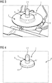
- Fig. 3 shows the gasket 1 arranged on the shaft 3.1 of the control element 3 in a state in which the appliance portion 5 is removed.
- the gasket 1 comprises a radial extent such that the whole horizontal cross section of the control element 3 is covered by said plate-shaped gasket 1.
- the gasket 1 may comprise an overall diameter of more than 40mm, specifically more than 50mm.
- Fig. 4 shows the appliance portion 5, specifically the appliance worktop comprising an opening 4 with a circular edge 4.1 through which the shaft 3.1 and a portion of the gasket 1, specifically the first gasket portion 6 and the coupling portion 8 (at least partially) extends through.
- the whole opening 4 is sealed by said gasket 1 thereby avoiding an undesired ingress of liquid through said opening, at least in situations in which a control knob to be arranged at the shaft 3.1 is removed.
- the diameter d8 of the coupling portion 8 is adapted to the diameter d4 of the opening 4 such that the coupling portion 8 comprises a tight fit or essentially a tight fit within said opening 4.
- the gasket 1 is not visible in case that a knob is provided at the shaft 3.1 because the gasket does not radially extend over the edge 4.1 of the opening 4 at the upper side of the appliance portion 5.
- the gasket 1 may comprise a soft elastic material.
- the gasket 1 may be a single-piece gasket.
- the elastic material may have a Shore-A hardness of 50 or less.
- the elastic material may be a silicone, specifically a heat-resistant silicone (e.g. heat resistant up to 280°C).
- the gasket 1 may be treated with a lubricant, e.g. with talc. According to embodiments, the whole gasket 1 or only a certain surface portion may be treated with said lubricant.
Landscapes
- Engineering & Computer Science (AREA)
- General Engineering & Computer Science (AREA)
- Mechanical Engineering (AREA)
- Physics & Mathematics (AREA)
- General Physics & Mathematics (AREA)
- Automation & Control Theory (AREA)
- Chemical & Material Sciences (AREA)
- Combustion & Propulsion (AREA)
- Gasket Seals (AREA)
Abstract
- a first gasket portion (6) being adapted to provide a sealed connection around the shaft (3.1) of the control element (3);
- a second gasket portion (7) adapted to be arranged below said horizontal appliance portion (5); and
- a coupling portion (8) for coupling said first and second gasket portions (6, 7);
wherein said gasket (1) is adapted to seal a ring-shaped passage (2) between said shaft (3.1) of the control element (3) and the edge (4.1) of the opening (4) of the horizontal appliance portion (5) in order to avoid an ingress of liquid into one or more control element portions arranged below the gasket.
Description
- The present invention relates generally to the field of household appliances. More specifically, the present invention is related to a gasket for a gas hob adapted to avoid ingress of liquid.
- Gas hobs are known in prior art. Said gas hobs comprise a horizontal hop portion, e.g. a hob worktop at which one or more knobs are provided for controlling the gas flow to the gas burners. Below the horizontal hop portion one or more gas taps are provided. Each gas tap comprises a shaft extending through an opening of the horizontal hop portion. In order to seal the opening of the work top, gaskets are known which extend along the edge of the opening in order to provide a sealing of the opening in cases when a knob is attached to the shaft.
- However, known gaskets do not provide a sealing in case that the knob is removed from the shaft.
- It is an objective of embodiments of the present invention to provide a gasket which comprises a simple design, which can be assembled easily and which provides a sealing of the opening also in case that the knob of the control element is removed. The objective is solved by the features of the independent claims. Preferred embodiments are given in the dependent claims. If not explicitly indicated otherwise, embodiments of the invention can be freely combined with each other.
- According to an aspect, the invention relates to a gasket for sealing a passage of a shaft of a control element of a household appliance through an appliance portion, specifically a horizontal appliance portion. The gasket comprises:
- a first gasket portion being adapted to provide a sealed connection around the shaft of the control element;
- a second gasket portion adapted to be arranged below said appliance portion; and
- a coupling portion for coupling said first and second gasket portions.
- Said gasket is adapted to seal a ring-shaped passage between said shaft of the control element and the edge of the opening of the appliance portion in order to avoid ingress of liquid into one or more control element portions arranged below the gasket.
- Said gasket is advantageous, because the passage between said shaft of the control element and the edge of the opening of the appliance portion is completely sealed even in case that a knob for actuating the control element, e.g. a gas tap, is not installed at the shaft.
- According to embodiments, said gasket comprises a stepped contour with a lower annular portion provided by the second gasket portion and an upper annular portion provided by a first section of the coupling portion. Said lower annular portion is adapted to be received below said appliance portion and may be further adapted to lie flat against the lower surface of the appliance portion in order to provide a sealing between the gasket and the appliance portion. The upper annular portion may protrude through said opening provided in the appliance portion. Said upper annular portion may be arranged flush with the upper surface of the appliance portion or may protrude upwardly from said upper surface of the appliance portion.
- According to embodiments, said lower annular portion and said upper annular portion are coupled by a ring-shaped or tube-shaped third section of the coupling portion vertically extending between said upper and lower annular portion. By means of said third section of the coupling portion, the upper and lower annular portion are arranged at a distance to each other. Said distance may be equal or greater than the thickness of the appliance portion, specifically, the thickness of the appliance worktop.
- According to embodiments, the first gasket portion may comprise a lip or neckband protruding upwardly from the coupling portion. Said lip or neckband may protrude upwardly from said upper annular portion and may be adapted to provide a close fit at the shaft. The lip or neckband provides a sealed passage of the shaft through the gasket.
- According to embodiments, said coupling portion comprises a cup-like, conical or tapered shape which opens downwardly. In addition, the gasket may comprise a stepped shape. Said gasket may be rotationally symmetric with respect to a vertical central axis which coincides with the longitudinal vertical axis of the shaft. Said upper annular portion may comprise a smaller diameter than the lower annular portion. Thereby it is possible to provide a sealed protection of the control element, specifically an electric switch included in said control element, arranged below the gasket without a gasket portion which encompasses the horizontal hop portion at its upper surface.
- According to embodiments, the second gasket portion comprises an annular, plate-like shape. Due to the annular, plate-like shape, the second gasket portion is adapted to lie flat against the lower surface of the appliance portion.
- According to embodiments, the radial width of the second gasket portion is greater than the radial width of the coupling portion. Thereby a large contact surface between the gasket and the lower surface of the appliance portion is obtained.
- According to embodiments, said coupling portion comprises a diameter which is equal or essentially equal to the diameter of the opening included in the appliance portion. Thereby a squeeze-connection between the gasket and the edge of the opening provided in the appliance portion is obtained.
- According to embodiments, said gasket is a single-piece gasket made of an elastomer. The gasket may be formed using a single injection moulding process based on which all portions of the gasket are manufactured. So, in other words, the gasket is not assembled using multiple parts but is manufactured as a one-piece part.
- According to embodiments, said gasket is made of silicone. Thereby a high elasticity and deformability of the gasket is obtained. Said silicone may be a high-temperature silicone with a temperature stability up to 280°C.
- According to embodiments, the gasket comprises an elastic material with a shore-A hardness of 55 or lower, preferably 50 or lower. Thereby a high elasticity is obtained.
- According to embodiments, at least a portion of the gasket is treated with talc or a lubricant. Thereby friction noise can be prevented.
- According to embodiments, the first gasket portion is adapted to enclose the shaft such that the first gasket portion remains in its position at the shaft when pushing said shaft downwardly. Thus, when pushing the shaft, the first gasket portion does not move or slide along the shaft but the gasket, specifically the coupling portion, is elastically deformed.
- According to embodiments, the coupling portion is adapted to be reversibly deformed when pushing the shaft downwardly. Specifically, the coupling portion may deflect downwardly when pushing the button. Thus, the gasket is only deformed but not moved along the shaft which enhances the sealing effect.
- According to a further aspect, the invention relates to a household appliance, specifically a gas hob comprising an appliance portion, preferably an appliance worktop and one or more control elements provided at said appliance portion. The control element comprises a shaft. An area between said appliance portion and the shaft of the control element is sealed by a gasket according to anyone of the upper-described embodiments.
- The term household appliance as used in the present disclosure may refer to any appliance comprising a control element with a shaft, specifically hobs, washing machines, dish washers etc.
- The term "essentially" or "approximately" as used in the present disclosure means deviations from the exact value by +/- 10%, preferably by +/- 5% and/or deviations in the form of changes that are insignificant for the function.
- The various aspects of the invention, including its particular features and advantages, will be readily understood from the following detailed description and the accompanying drawings, in which:
- Fig. 1
- shows an example schematic side view of a gasket;
- Fig. 2
- shows the gasket according to
Fig. 1 in an installed position at the gas hop in a lateral sectional view; - Fig. 3
- shows a perspective top view onto the gasket provided at a shaft of a control element when the horizontal hob portion is removed; and
- Fig. 4
- shows a perspective top view onto the gasket provided at a shaft of a control element when the horizontal hob portion is installed.
- The present invention will now be described more fully with reference to the accompanying drawings, in which example embodiments are shown. However, this invention should not be construed as limited to the embodiments set forth herein. Throughout the following description similar reference numerals have been used to denote similar elements, parts, items or features, when applicable.
-
Fig. 1 shows a schematic illustration of a gasket 1 according to an example embodiment. In a broad sense, the gasket 1 comprises a cap-like, plate-like or bell-like shape. Said gasket 1 comprises a stepped shape which narrows from bottom to top. Said gasket 1 is adapted to seal a passage provided between a horizontal portion of a gas hob, preferably between a horizontal worktop of a gas hop and a shaft of a control element provided through an opening within said horizontal portion, respectively, a horizontal worktop of the gas hop. In the following, said horizontal portion is also referred to as horizontal appliance portion. The control element may be, for example, a gas tap of a gas hob. - The gasket 1 comprises a
first gasket portion 6, preferably forming an upper gasket portion, asecond gasket portion 7, preferably forming a lower gasket portion and acoupling portion 8 being arranged between said first andsecond gasket portions second gasket portions - The
first gasket portion 6 may comprise or may be formed by a lip 6.1 or neckband protruding upwardly in order to provide a liquid tight sealing at the shaft of the control element. As shown inFig. 2 , thefirst gasket portion 6 may comprise an opening 6.2 through which said shaft 3.1 of the control element 3 is passing through. Saidfirst gasket portion 6, preferably said lip 6.1 may at least partially extend along the shaft 3.1, i.e. thefirst gasket portion 6, respectively, said lip 6.1 provides a tubular passage for said shaft 3.1. The diameter of the opening 6.2 is chosen equal or slightly smaller than the diameter of the shaft 3.1 in order to provide a tight fit of the gasket 1 at the shaft 3.1. In case that the shaft 3.1 is pressed, thefirst gasket portion 6 may not move along the shaft 3.1 but will move together with the shaft 3.1 downwardly. Thereby, the gasket 1, specifically thecoupling portion 8, is reversibly deformed and returns into its originally shape if the pressure on the shaft 3.1 is released. - The
first gasket portion 6 is coupled by mean of a rounded transition portion 6.3 with thecoupling portion 8. Saidcoupling portion 8 comprises at least a first, a second and a third section 8.1, 8.2, 8.3. Said first section 8.1 is attached to the transition portion 6.3 and comprises an annular shape. Said first section 8.1 may be arranged in a horizontal plane which is perpendicular or essentially perpendicular to the shaft 3.1 of the control element. In other words, the first section 3.1 is a planar section which is arranged parallel or essentially parallel to thehorizontal appliance portion 5 of the gas hob. - The first section 8.1 of the
coupling portion 8 may be a ring-shaped section which comprises a geometry equal or essentially equal to theopening 4 within thehorizontal appliance portion 5, through which said shaft 3.1 is protruding. So in other words, the first section 8.1 covers essentially the whole opening cross-section between said shaft and an edge 4.1, preferably a circular or ring-shaped edge 4.1 of saidopening 4. - The second section 8.2 of the
coupling portion 8 is a transition section between said first section 8.1 and said third section 8.3 of saidcoupling portion 8. Said second section 8.2 may provide a transition between said horizontally arranged first section 8.1 and said vertically arranged third section 8.3. Said second section 8.2 may provide a rounded transition between said first and third section 8.1, 8.3. - The third section 8.3 of the
coupling portion 8 is a tubular portion which is arranged vertically or essentially vertically, i.e. the longitudinal axis of said third section 8.3 extends in vertical or essentially vertical direction. The third section 8.3 is adapted to couple an upper portion of the gasket 1 (e.g. built by thefirst gasket portion 6 and the first and second section 8.1, 8.2 of the coupling portion 8) with a bottom portion of the gasket 1, e.g. build by thesecond gasket portion 7. Said third section 8.3 radially limits an interior space 1.1 within the gasket 1, through which said shaft 3.1 extends through. - Said
coupling portion 8, specifically, said third section 8.3 of thecoupling portion 8 is coupled with thesecond gasket portion 7 using a transition portion 8.4. Said transition portion 8.4 may be adapted to provide a coupling between the vertically arranged third section 8.3 and the horizontally arrangedsecond gasket portion 7. For example, the transition portion 8.4 may provide a rounded transition between the third section 8.3 of thecoupling portion 8 and thesecond gasket portion 7. - The
second gasket portion 7 may be an annular, respectively, ring-shaped, planar portion. Saidsecond gasket portion 7 is adapted to be arranged below theappliance portion 5. The radial width W7 of thesecond gasket portion 7 may be greater than the radial width W8 of thecoupling portion 8, respectively, greater than the height h of thecoupling portion 8. Thus, thesecond gasket portion 7 comprises a significant extension below theplanar appliance portion 5 thereby avoiding an ingress of liquid through theopening 4 in an area below said gasket 1. Saidsecond gasket portion 7 abuts with its planar upper surface against the lower surface 5.1 of theappliance portion 5. -
Fig. 3 shows the gasket 1 arranged on the shaft 3.1 of the control element 3 in a state in which theappliance portion 5 is removed. The gasket 1 comprises a radial extent such that the whole horizontal cross section of the control element 3 is covered by said plate-shaped gasket 1. For example, the gasket 1 may comprise an overall diameter of more than 40mm, specifically more than 50mm. -
Fig. 4 shows theappliance portion 5, specifically the appliance worktop comprising anopening 4 with a circular edge 4.1 through which the shaft 3.1 and a portion of the gasket 1, specifically thefirst gasket portion 6 and the coupling portion 8 (at least partially) extends through. As shown inFig. 2 andFig. 4 , thewhole opening 4 is sealed by said gasket 1 thereby avoiding an undesired ingress of liquid through said opening, at least in situations in which a control knob to be arranged at the shaft 3.1 is removed. The diameter d8 of thecoupling portion 8 is adapted to the diameter d4 of theopening 4 such that thecoupling portion 8 comprises a tight fit or essentially a tight fit within saidopening 4. As shown inFig. 4 , the gasket 1 is not visible in case that a knob is provided at the shaft 3.1 because the gasket does not radially extend over the edge 4.1 of theopening 4 at the upper side of theappliance portion 5. - In order to enhance the sealing effect, the gasket 1 may comprise a soft elastic material. The gasket 1 may be a single-piece gasket. According to an embodiment, the elastic material may have a Shore-A hardness of 50 or less. The elastic material may be a silicone, specifically a heat-resistant silicone (e.g. heat resistant up to 280°C).
- In order to avoid any friction noise, the gasket 1 may be treated with a lubricant, e.g. with talc. According to embodiments, the whole gasket 1 or only a certain surface portion may be treated with said lubricant.
- It should be noted that the description and drawings merely illustrate the principles of the proposed gasket and household appliance. Those skilled in the art will be able to implement various arrangements that, although not explicitly described or shown herein, embody the principles of the invention.
-
- 1
- gasket
- 1.1
- interior space
- 2
- passage
- 3
- control element
- 3.1
- shaft
- 4
- opening
- 4.1
- edge
- 5
- appliance portion
- 5.1
- lower surface
- 6
- first gasket portion
- 6.1
- lip
- 6.2
- opening
- 6.3
- transition portion
- 7
- second gasket portion
- 8
- coupling portion
- 8.1
- first section
- 8.2
- second section
- 8.3
- third section
- 8.4
- transition portion
- d4
- diameter
- d8
- diameter
- h
- height
- W7
- radial width of second gasket portion
- W8
- radial width of coupling portion
Claims (15)
- Gasket for sealing a passage (2) of a shaft (3.1) of a control element (3) of a household appliance through a appliance portion (5), the gasket (1) comprising:- a first gasket portion (6) being adapted to provide a sealed connection around the shaft (3.1) of the control element (3);- a second gasket portion (7) adapted to be arranged below said appliance portion (5); and- a coupling portion (8) for coupling said first and second gasket portions (6, 7);wherein said gasket (1) is adapted to seal a ring-shaped passage (2) between said shaft (3.1) of the control element (3) and the edge (4.1) of the opening (4) of the appliance portion (5) in order to avoid an ingress of liquid into one or more control element portions arranged below the gasket.
- Gasket according to claim 1, comprising a stepped contour with a lower annular portion provided by the second gasket portion (7) and an upper annular portion provided by a first section (8.1) of the coupling portion (8).
- Gasket according to claim 2, wherein said lower annular portion and said upper annular portion are coupled by a ring-shaped third section (8.3) of the coupling portion (8) vertically extending between said upper and lower annular portion.
- Gasket according to anyone of the preceding claims, wherein the first gasket portion (6) comprises a lip (6.1) protruding upwardly from the coupling portion (8).
- Gasket according to anyone of the preceding claims, wherein said coupling portion (8) comprises a cup-like, conical or tapered shape which opens downwardly.
- Gasket according to anyone of the preceding claims, wherein the second gasket portion (7) comprises an annular, plate-like shape.
- Gasket according to anyone of the preceding claims, wherein the radial width (W7) of the second gasket portion (7) is greater than the radial width (W8) of the coupling portion (8).
- Gasket according to anyone of the preceding claims, wherein said coupling portion (8) comprises a diameter (d8) which is equal or essentially equal to the diameter (d4) of the opening (4) included in the appliance portion (5).
- Gasket according to anyone of the preceding claims, wherein said gasket (1) is a single-piece gasket made of an elastomer.
- Gasket according to anyone of the preceding claims, wherein said gasket (1) is made of silicone.
- Gasket according to anyone of the preceding claims, comprising an elastic material with a shore-A hardness of 55 or lower, preferably 50 or lower.
- Gasket according to anyone of the preceding claims, wherein at least a portion of the gasket (1) is treated with talc or a lubricant.
- Gasket according to anyone of the preceding claims, wherein the first gasket portion (6) is adapted to enclose the shaft (3.1) such that the first gasket portion (6) remains in its position at the shaft (3.1) when pushing said shaft (3.1) downwardly.
- Gasket according to anyone of the preceding claims, wherein the coupling portion (8) is adapted to be reversibly deformed when pushing the shaft (3.1) downwardly.
- Household appliance, specifically gas hob comprising a appliance portion (5), preferably an appliance worktop and one or more control elements (3) provided at said appliance portion (5), the control element comprising a shaft (3.1), wherein an area between said appliance portion (5) and a shaft (3.1) of the control element (3) is sealed by a gasket (1) according to anyone of the preceding claims.
Priority Applications (2)
| Application Number | Priority Date | Filing Date | Title |
|---|---|---|---|
| ES17169853T ES2898956T3 (en) | 2017-05-08 | 2017-05-08 | Sealing gasket and gas hob comprising a gasket |
| EP17169853.3A EP3401576B1 (en) | 2017-05-08 | 2017-05-08 | Gasket and gas hob comprising a gasket |
Applications Claiming Priority (1)
| Application Number | Priority Date | Filing Date | Title |
|---|---|---|---|
| EP17169853.3A EP3401576B1 (en) | 2017-05-08 | 2017-05-08 | Gasket and gas hob comprising a gasket |
Publications (2)
| Publication Number | Publication Date |
|---|---|
| EP3401576A1 true EP3401576A1 (en) | 2018-11-14 |
| EP3401576B1 EP3401576B1 (en) | 2021-09-08 |
Family
ID=58692402
Family Applications (1)
| Application Number | Title | Priority Date | Filing Date |
|---|---|---|---|
| EP17169853.3A Active EP3401576B1 (en) | 2017-05-08 | 2017-05-08 | Gasket and gas hob comprising a gasket |
Country Status (2)
| Country | Link |
|---|---|
| EP (1) | EP3401576B1 (en) |
| ES (1) | ES2898956T3 (en) |
Citations (6)
| Publication number | Priority date | Publication date | Assignee | Title |
|---|---|---|---|---|
| GB2013287A (en) * | 1978-02-24 | 1979-08-08 | Fluid Transfer Ltd | Seals |
| EP1103747A1 (en) * | 1999-11-26 | 2001-05-30 | Brandt Cooking | Flexible sealing |
| ES2200723A1 (en) * | 2003-10-22 | 2004-03-01 | Bsh Electrodomesticos Espana | Gas kitchen fire. (Machine-translation by Google Translate, not legally binding) |
| JP2012031951A (en) * | 2010-07-30 | 2012-02-16 | Iwai Kikai Kogyo Co Ltd | Diaphragm barrier membrane |
| WO2017026960A1 (en) * | 2015-08-10 | 2017-02-16 | Arcelik Anonim Sirketi | A household appliance comprising a knob with illuminated outer periphery |
| WO2017061212A1 (en) * | 2015-10-05 | 2017-04-13 | Nok株式会社 | Dust cover |
-
2017
- 2017-05-08 EP EP17169853.3A patent/EP3401576B1/en active Active
- 2017-05-08 ES ES17169853T patent/ES2898956T3/en active Active
Patent Citations (6)
| Publication number | Priority date | Publication date | Assignee | Title |
|---|---|---|---|---|
| GB2013287A (en) * | 1978-02-24 | 1979-08-08 | Fluid Transfer Ltd | Seals |
| EP1103747A1 (en) * | 1999-11-26 | 2001-05-30 | Brandt Cooking | Flexible sealing |
| ES2200723A1 (en) * | 2003-10-22 | 2004-03-01 | Bsh Electrodomesticos Espana | Gas kitchen fire. (Machine-translation by Google Translate, not legally binding) |
| JP2012031951A (en) * | 2010-07-30 | 2012-02-16 | Iwai Kikai Kogyo Co Ltd | Diaphragm barrier membrane |
| WO2017026960A1 (en) * | 2015-08-10 | 2017-02-16 | Arcelik Anonim Sirketi | A household appliance comprising a knob with illuminated outer periphery |
| WO2017061212A1 (en) * | 2015-10-05 | 2017-04-13 | Nok株式会社 | Dust cover |
Also Published As
| Publication number | Publication date |
|---|---|
| ES2898956T3 (en) | 2022-03-09 |
| EP3401576B1 (en) | 2021-09-08 |
Similar Documents
| Publication | Publication Date | Title |
|---|---|---|
| EP2877784B1 (en) | Cooking device with a sealing element for knobs | |
| CN101416838B (en) | Pressure cooker equipped with a high-pressure safety system | |
| US11519610B2 (en) | Sealing temperature sensor assembly for an appliance cooktop | |
| RU2390818C2 (en) | Sealing gasket to be installed under adjusting handle of kitchen stove | |
| CN109276148B (en) | Steam valve, heat preservation cover plate assembly, cover body structure and cooking utensil | |
| KR101332512B1 (en) | A lid for cooker | |
| CN107752742B (en) | Sealing ring on cover plate assembly, upper cover assembly and electric appliance | |
| EP3401576B1 (en) | Gasket and gas hob comprising a gasket | |
| EP3933272B1 (en) | Gas stove | |
| CN105588154A (en) | Gas cooking place and cooking area assembly | |
| CN110037535B (en) | Cooking appliance and cooking appliance cover | |
| CN206354913U (en) | Steam valve and cooking apparatus | |
| KR100267949B1 (en) | Handling device | |
| US10564659B2 (en) | Electric valve device, particularly for household electrical appliances | |
| JP2019509845A (en) | Steam valves and cookware | |
| EP3663889B1 (en) | A sealing element for button-controlled cooking devices | |
| KR102423425B1 (en) | Rice cooker | |
| CN214510808U (en) | Sealing ring and cooking utensil with same | |
| US5241158A (en) | Electric hotplate | |
| EP4150257A1 (en) | Gas stove | |
| CN223695562U (en) | Cover assembly and cooking utensils having it | |
| EP4042072B1 (en) | Gas stove | |
| CN206354883U (en) | Steam valve and cooking apparatus | |
| KR200253016Y1 (en) | structure for maintain gap between outer panel and inner panel of door in gas oven range | |
| CN217338259U (en) | Upper cover and cooking utensil with same |
Legal Events
| Date | Code | Title | Description |
|---|---|---|---|
| PUAI | Public reference made under article 153(3) epc to a published international application that has entered the european phase |
Free format text: ORIGINAL CODE: 0009012 |
|
| STAA | Information on the status of an ep patent application or granted ep patent |
Free format text: STATUS: THE APPLICATION HAS BEEN PUBLISHED |
|
| AK | Designated contracting states |
Kind code of ref document: A1 Designated state(s): AL AT BE BG CH CY CZ DE DK EE ES FI FR GB GR HR HU IE IS IT LI LT LU LV MC MK MT NL NO PL PT RO RS SE SI SK SM TR |
|
| AX | Request for extension of the european patent |
Extension state: BA ME |
|
| STAA | Information on the status of an ep patent application or granted ep patent |
Free format text: STATUS: REQUEST FOR EXAMINATION WAS MADE |
|
| 17P | Request for examination filed |
Effective date: 20190514 |
|
| RBV | Designated contracting states (corrected) |
Designated state(s): AL AT BE BG CH CY CZ DE DK EE ES FI FR GB GR HR HU IE IS IT LI LT LU LV MC MK MT NL NO PL PT RO RS SE SI SK SM TR |
|
| STAA | Information on the status of an ep patent application or granted ep patent |
Free format text: STATUS: EXAMINATION IS IN PROGRESS |
|
| 17Q | First examination report despatched |
Effective date: 20191022 |
|
| REG | Reference to a national code |
Ref country code: DE Ref legal event code: R079 Ref document number: 602017045545 Country of ref document: DE Free format text: PREVIOUS MAIN CLASS: F16J0003020000 Ipc: G05G0001080000 |
|
| RIC1 | Information provided on ipc code assigned before grant |
Ipc: G05G 25/04 20060101ALI20210324BHEP Ipc: F24C 3/12 20060101ALI20210324BHEP Ipc: F16J 3/04 20060101ALI20210324BHEP Ipc: F16J 3/02 20060101ALI20210324BHEP Ipc: G05G 1/08 20060101AFI20210324BHEP |
|
| GRAP | Despatch of communication of intention to grant a patent |
Free format text: ORIGINAL CODE: EPIDOSNIGR1 |
|
| STAA | Information on the status of an ep patent application or granted ep patent |
Free format text: STATUS: GRANT OF PATENT IS INTENDED |
|
| INTG | Intention to grant announced |
Effective date: 20210430 |
|
| GRAS | Grant fee paid |
Free format text: ORIGINAL CODE: EPIDOSNIGR3 |
|
| GRAA | (expected) grant |
Free format text: ORIGINAL CODE: 0009210 |
|
| STAA | Information on the status of an ep patent application or granted ep patent |
Free format text: STATUS: THE PATENT HAS BEEN GRANTED |
|
| AK | Designated contracting states |
Kind code of ref document: B1 Designated state(s): AL AT BE BG CH CY CZ DE DK EE ES FI FR GB GR HR HU IE IS IT LI LT LU LV MC MK MT NL NO PL PT RO RS SE SI SK SM TR |
|
| REG | Reference to a national code |
Ref country code: GB Ref legal event code: FG4D |
|
| REG | Reference to a national code |
Ref country code: CH Ref legal event code: EP Ref country code: AT Ref legal event code: REF Ref document number: 1429151 Country of ref document: AT Kind code of ref document: T Effective date: 20210915 |
|
| REG | Reference to a national code |
Ref country code: DE Ref legal event code: R096 Ref document number: 602017045545 Country of ref document: DE |
|
| REG | Reference to a national code |
Ref country code: IE Ref legal event code: FG4D |
|
| REG | Reference to a national code |
Ref country code: LT Ref legal event code: MG9D |
|
| REG | Reference to a national code |
Ref country code: NL Ref legal event code: MP Effective date: 20210908 |
|
| PG25 | Lapsed in a contracting state [announced via postgrant information from national office to epo] |
Ref country code: RS Free format text: LAPSE BECAUSE OF FAILURE TO SUBMIT A TRANSLATION OF THE DESCRIPTION OR TO PAY THE FEE WITHIN THE PRESCRIBED TIME-LIMIT Effective date: 20210908 Ref country code: SE Free format text: LAPSE BECAUSE OF FAILURE TO SUBMIT A TRANSLATION OF THE DESCRIPTION OR TO PAY THE FEE WITHIN THE PRESCRIBED TIME-LIMIT Effective date: 20210908 Ref country code: NO Free format text: LAPSE BECAUSE OF FAILURE TO SUBMIT A TRANSLATION OF THE DESCRIPTION OR TO PAY THE FEE WITHIN THE PRESCRIBED TIME-LIMIT Effective date: 20211208 Ref country code: HR Free format text: LAPSE BECAUSE OF FAILURE TO SUBMIT A TRANSLATION OF THE DESCRIPTION OR TO PAY THE FEE WITHIN THE PRESCRIBED TIME-LIMIT Effective date: 20210908 Ref country code: FI Free format text: LAPSE BECAUSE OF FAILURE TO SUBMIT A TRANSLATION OF THE DESCRIPTION OR TO PAY THE FEE WITHIN THE PRESCRIBED TIME-LIMIT Effective date: 20210908 Ref country code: BG Free format text: LAPSE BECAUSE OF FAILURE TO SUBMIT A TRANSLATION OF THE DESCRIPTION OR TO PAY THE FEE WITHIN THE PRESCRIBED TIME-LIMIT Effective date: 20211208 Ref country code: LT Free format text: LAPSE BECAUSE OF FAILURE TO SUBMIT A TRANSLATION OF THE DESCRIPTION OR TO PAY THE FEE WITHIN THE PRESCRIBED TIME-LIMIT Effective date: 20210908 |
|
| REG | Reference to a national code |
Ref country code: AT Ref legal event code: MK05 Ref document number: 1429151 Country of ref document: AT Kind code of ref document: T Effective date: 20210908 |
|
| PG25 | Lapsed in a contracting state [announced via postgrant information from national office to epo] |
Ref country code: LV Free format text: LAPSE BECAUSE OF FAILURE TO SUBMIT A TRANSLATION OF THE DESCRIPTION OR TO PAY THE FEE WITHIN THE PRESCRIBED TIME-LIMIT Effective date: 20210908 Ref country code: GR Free format text: LAPSE BECAUSE OF FAILURE TO SUBMIT A TRANSLATION OF THE DESCRIPTION OR TO PAY THE FEE WITHIN THE PRESCRIBED TIME-LIMIT Effective date: 20211209 |
|
| REG | Reference to a national code |
Ref country code: ES Ref legal event code: FG2A Ref document number: 2898956 Country of ref document: ES Kind code of ref document: T3 Effective date: 20220309 |
|
| PG25 | Lapsed in a contracting state [announced via postgrant information from national office to epo] |
Ref country code: AT Free format text: LAPSE BECAUSE OF FAILURE TO SUBMIT A TRANSLATION OF THE DESCRIPTION OR TO PAY THE FEE WITHIN THE PRESCRIBED TIME-LIMIT Effective date: 20210908 |
|
| PG25 | Lapsed in a contracting state [announced via postgrant information from national office to epo] |
Ref country code: IS Free format text: LAPSE BECAUSE OF FAILURE TO SUBMIT A TRANSLATION OF THE DESCRIPTION OR TO PAY THE FEE WITHIN THE PRESCRIBED TIME-LIMIT Effective date: 20220108 Ref country code: SM Free format text: LAPSE BECAUSE OF FAILURE TO SUBMIT A TRANSLATION OF THE DESCRIPTION OR TO PAY THE FEE WITHIN THE PRESCRIBED TIME-LIMIT Effective date: 20210908 Ref country code: SK Free format text: LAPSE BECAUSE OF FAILURE TO SUBMIT A TRANSLATION OF THE DESCRIPTION OR TO PAY THE FEE WITHIN THE PRESCRIBED TIME-LIMIT Effective date: 20210908 Ref country code: RO Free format text: LAPSE BECAUSE OF FAILURE TO SUBMIT A TRANSLATION OF THE DESCRIPTION OR TO PAY THE FEE WITHIN THE PRESCRIBED TIME-LIMIT Effective date: 20210908 Ref country code: PT Free format text: LAPSE BECAUSE OF FAILURE TO SUBMIT A TRANSLATION OF THE DESCRIPTION OR TO PAY THE FEE WITHIN THE PRESCRIBED TIME-LIMIT Effective date: 20220110 Ref country code: PL Free format text: LAPSE BECAUSE OF FAILURE TO SUBMIT A TRANSLATION OF THE DESCRIPTION OR TO PAY THE FEE WITHIN THE PRESCRIBED TIME-LIMIT Effective date: 20210908 Ref country code: NL Free format text: LAPSE BECAUSE OF FAILURE TO SUBMIT A TRANSLATION OF THE DESCRIPTION OR TO PAY THE FEE WITHIN THE PRESCRIBED TIME-LIMIT Effective date: 20210908 Ref country code: EE Free format text: LAPSE BECAUSE OF FAILURE TO SUBMIT A TRANSLATION OF THE DESCRIPTION OR TO PAY THE FEE WITHIN THE PRESCRIBED TIME-LIMIT Effective date: 20210908 Ref country code: CZ Free format text: LAPSE BECAUSE OF FAILURE TO SUBMIT A TRANSLATION OF THE DESCRIPTION OR TO PAY THE FEE WITHIN THE PRESCRIBED TIME-LIMIT Effective date: 20210908 Ref country code: AL Free format text: LAPSE BECAUSE OF FAILURE TO SUBMIT A TRANSLATION OF THE DESCRIPTION OR TO PAY THE FEE WITHIN THE PRESCRIBED TIME-LIMIT Effective date: 20210908 |
|
| REG | Reference to a national code |
Ref country code: DE Ref legal event code: R097 Ref document number: 602017045545 Country of ref document: DE |
|
| PLBE | No opposition filed within time limit |
Free format text: ORIGINAL CODE: 0009261 |
|
| STAA | Information on the status of an ep patent application or granted ep patent |
Free format text: STATUS: NO OPPOSITION FILED WITHIN TIME LIMIT |
|
| PG25 | Lapsed in a contracting state [announced via postgrant information from national office to epo] |
Ref country code: DK Free format text: LAPSE BECAUSE OF FAILURE TO SUBMIT A TRANSLATION OF THE DESCRIPTION OR TO PAY THE FEE WITHIN THE PRESCRIBED TIME-LIMIT Effective date: 20210908 |
|
| 26N | No opposition filed |
Effective date: 20220609 |
|
| PG25 | Lapsed in a contracting state [announced via postgrant information from national office to epo] |
Ref country code: SI Free format text: LAPSE BECAUSE OF FAILURE TO SUBMIT A TRANSLATION OF THE DESCRIPTION OR TO PAY THE FEE WITHIN THE PRESCRIBED TIME-LIMIT Effective date: 20210908 |
|
| REG | Reference to a national code |
Ref country code: DE Ref legal event code: R119 Ref document number: 602017045545 Country of ref document: DE |
|
| REG | Reference to a national code |
Ref country code: CH Ref legal event code: PL |
|
| REG | Reference to a national code |
Ref country code: BE Ref legal event code: MM Effective date: 20220531 |
|
| PG25 | Lapsed in a contracting state [announced via postgrant information from national office to epo] |
Ref country code: MC Free format text: LAPSE BECAUSE OF FAILURE TO SUBMIT A TRANSLATION OF THE DESCRIPTION OR TO PAY THE FEE WITHIN THE PRESCRIBED TIME-LIMIT Effective date: 20210908 Ref country code: LU Free format text: LAPSE BECAUSE OF NON-PAYMENT OF DUE FEES Effective date: 20220508 Ref country code: LI Free format text: LAPSE BECAUSE OF NON-PAYMENT OF DUE FEES Effective date: 20220531 Ref country code: CH Free format text: LAPSE BECAUSE OF NON-PAYMENT OF DUE FEES Effective date: 20220531 |
|
| PG25 | Lapsed in a contracting state [announced via postgrant information from national office to epo] |
Ref country code: IE Free format text: LAPSE BECAUSE OF NON-PAYMENT OF DUE FEES Effective date: 20220508 |
|
| PG25 | Lapsed in a contracting state [announced via postgrant information from national office to epo] |
Ref country code: DE Free format text: LAPSE BECAUSE OF NON-PAYMENT OF DUE FEES Effective date: 20221201 Ref country code: BE Free format text: LAPSE BECAUSE OF NON-PAYMENT OF DUE FEES Effective date: 20220531 |
|
| P01 | Opt-out of the competence of the unified patent court (upc) registered |
Effective date: 20230625 |
|
| PG25 | Lapsed in a contracting state [announced via postgrant information from national office to epo] |
Ref country code: HU Free format text: LAPSE BECAUSE OF FAILURE TO SUBMIT A TRANSLATION OF THE DESCRIPTION OR TO PAY THE FEE WITHIN THE PRESCRIBED TIME-LIMIT; INVALID AB INITIO Effective date: 20170508 |
|
| PG25 | Lapsed in a contracting state [announced via postgrant information from national office to epo] |
Ref country code: MK Free format text: LAPSE BECAUSE OF FAILURE TO SUBMIT A TRANSLATION OF THE DESCRIPTION OR TO PAY THE FEE WITHIN THE PRESCRIBED TIME-LIMIT Effective date: 20210908 Ref country code: CY Free format text: LAPSE BECAUSE OF FAILURE TO SUBMIT A TRANSLATION OF THE DESCRIPTION OR TO PAY THE FEE WITHIN THE PRESCRIBED TIME-LIMIT Effective date: 20210908 |
|
| PGFP | Annual fee paid to national office [announced via postgrant information from national office to epo] |
Ref country code: ES Payment date: 20240610 Year of fee payment: 8 |
|
| PG25 | Lapsed in a contracting state [announced via postgrant information from national office to epo] |
Ref country code: MT Free format text: LAPSE BECAUSE OF FAILURE TO SUBMIT A TRANSLATION OF THE DESCRIPTION OR TO PAY THE FEE WITHIN THE PRESCRIBED TIME-LIMIT Effective date: 20210908 |
|
| PGFP | Annual fee paid to national office [announced via postgrant information from national office to epo] |
Ref country code: GB Payment date: 20250520 Year of fee payment: 9 |
|
| PGFP | Annual fee paid to national office [announced via postgrant information from national office to epo] |
Ref country code: IT Payment date: 20250522 Year of fee payment: 9 |
|
| PGFP | Annual fee paid to national office [announced via postgrant information from national office to epo] |
Ref country code: FR Payment date: 20250526 Year of fee payment: 9 |
|
| PG25 | Lapsed in a contracting state [announced via postgrant information from national office to epo] |
Ref country code: TR Free format text: LAPSE BECAUSE OF FAILURE TO SUBMIT A TRANSLATION OF THE DESCRIPTION OR TO PAY THE FEE WITHIN THE PRESCRIBED TIME-LIMIT Effective date: 20210908 |