EP3401548A2 - Damping system for an e-charger - Google Patents
Damping system for an e-charger Download PDFInfo
- Publication number
- EP3401548A2 EP3401548A2 EP18167399.7A EP18167399A EP3401548A2 EP 3401548 A2 EP3401548 A2 EP 3401548A2 EP 18167399 A EP18167399 A EP 18167399A EP 3401548 A2 EP3401548 A2 EP 3401548A2
- Authority
- EP
- European Patent Office
- Prior art keywords
- dampener
- shaft
- rotation
- housing assembly
- axis
- Prior art date
- Legal status (The legal status is an assumption and is not a legal conclusion. Google has not performed a legal analysis and makes no representation as to the accuracy of the status listed.)
- Pending
Links
Images


Classifications
-
- F—MECHANICAL ENGINEERING; LIGHTING; HEATING; WEAPONS; BLASTING
- F04—POSITIVE - DISPLACEMENT MACHINES FOR LIQUIDS; PUMPS FOR LIQUIDS OR ELASTIC FLUIDS
- F04D—NON-POSITIVE-DISPLACEMENT PUMPS
- F04D29/00—Details, component parts, or accessories
- F04D29/66—Combating cavitation, whirls, noise, vibration or the like; Balancing
- F04D29/661—Combating cavitation, whirls, noise, vibration or the like; Balancing especially adapted for elastic fluid pumps
- F04D29/668—Combating cavitation, whirls, noise, vibration or the like; Balancing especially adapted for elastic fluid pumps damping or preventing mechanical vibrations
-
- F—MECHANICAL ENGINEERING; LIGHTING; HEATING; WEAPONS; BLASTING
- F02—COMBUSTION ENGINES; HOT-GAS OR COMBUSTION-PRODUCT ENGINE PLANTS
- F02B—INTERNAL-COMBUSTION PISTON ENGINES; COMBUSTION ENGINES IN GENERAL
- F02B33/00—Engines characterised by provision of pumps for charging or scavenging
- F02B33/32—Engines with pumps other than of reciprocating-piston type
- F02B33/34—Engines with pumps other than of reciprocating-piston type with rotary pumps
- F02B33/40—Engines with pumps other than of reciprocating-piston type with rotary pumps of non-positive-displacement type
-
- F—MECHANICAL ENGINEERING; LIGHTING; HEATING; WEAPONS; BLASTING
- F02—COMBUSTION ENGINES; HOT-GAS OR COMBUSTION-PRODUCT ENGINE PLANTS
- F02B—INTERNAL-COMBUSTION PISTON ENGINES; COMBUSTION ENGINES IN GENERAL
- F02B39/00—Component parts, details, or accessories relating to, driven charging or scavenging pumps, not provided for in groups F02B33/00 - F02B37/00
- F02B39/02—Drives of pumps; Varying pump drive gear ratio
- F02B39/08—Non-mechanical drives, e.g. fluid drives having variable gear ratio
- F02B39/10—Non-mechanical drives, e.g. fluid drives having variable gear ratio electric
-
- F—MECHANICAL ENGINEERING; LIGHTING; HEATING; WEAPONS; BLASTING
- F02—COMBUSTION ENGINES; HOT-GAS OR COMBUSTION-PRODUCT ENGINE PLANTS
- F02B—INTERNAL-COMBUSTION PISTON ENGINES; COMBUSTION ENGINES IN GENERAL
- F02B39/00—Component parts, details, or accessories relating to, driven charging or scavenging pumps, not provided for in groups F02B33/00 - F02B37/00
- F02B39/16—Other safety measures for, or other control of, pumps
-
- F—MECHANICAL ENGINEERING; LIGHTING; HEATING; WEAPONS; BLASTING
- F04—POSITIVE - DISPLACEMENT MACHINES FOR LIQUIDS; PUMPS FOR LIQUIDS OR ELASTIC FLUIDS
- F04D—NON-POSITIVE-DISPLACEMENT PUMPS
- F04D25/00—Pumping installations or systems
- F04D25/02—Units comprising pumps and their driving means
- F04D25/06—Units comprising pumps and their driving means the pump being electrically driven
- F04D25/0606—Units comprising pumps and their driving means the pump being electrically driven the electric motor being specially adapted for integration in the pump
-
- F—MECHANICAL ENGINEERING; LIGHTING; HEATING; WEAPONS; BLASTING
- F04—POSITIVE - DISPLACEMENT MACHINES FOR LIQUIDS; PUMPS FOR LIQUIDS OR ELASTIC FLUIDS
- F04D—NON-POSITIVE-DISPLACEMENT PUMPS
- F04D29/00—Details, component parts, or accessories
- F04D29/05—Shafts or bearings, or assemblies thereof, specially adapted for elastic fluid pumps
- F04D29/053—Shafts
-
- F—MECHANICAL ENGINEERING; LIGHTING; HEATING; WEAPONS; BLASTING
- F04—POSITIVE - DISPLACEMENT MACHINES FOR LIQUIDS; PUMPS FOR LIQUIDS OR ELASTIC FLUIDS
- F04D—NON-POSITIVE-DISPLACEMENT PUMPS
- F04D29/00—Details, component parts, or accessories
- F04D29/26—Rotors specially for elastic fluids
- F04D29/28—Rotors specially for elastic fluids for centrifugal or helico-centrifugal pumps for radial-flow or helico-centrifugal pumps
- F04D29/30—Vanes
-
- F—MECHANICAL ENGINEERING; LIGHTING; HEATING; WEAPONS; BLASTING
- F04—POSITIVE - DISPLACEMENT MACHINES FOR LIQUIDS; PUMPS FOR LIQUIDS OR ELASTIC FLUIDS
- F04D—NON-POSITIVE-DISPLACEMENT PUMPS
- F04D29/00—Details, component parts, or accessories
- F04D29/40—Casings; Connections of working fluid
- F04D29/42—Casings; Connections of working fluid for radial or helico-centrifugal pumps
- F04D29/4206—Casings; Connections of working fluid for radial or helico-centrifugal pumps especially adapted for elastic fluid pumps
-
- F—MECHANICAL ENGINEERING; LIGHTING; HEATING; WEAPONS; BLASTING
- F04—POSITIVE - DISPLACEMENT MACHINES FOR LIQUIDS; PUMPS FOR LIQUIDS OR ELASTIC FLUIDS
- F04D—NON-POSITIVE-DISPLACEMENT PUMPS
- F04D29/00—Details, component parts, or accessories
- F04D29/60—Mounting; Assembling; Disassembling
- F04D29/62—Mounting; Assembling; Disassembling of radial or helico-centrifugal pumps
- F04D29/624—Mounting; Assembling; Disassembling of radial or helico-centrifugal pumps especially adapted for elastic fluid pumps
Definitions
- the present disclosure generally relates to an electrically driven compressor assembly such as an e-charger, and more particularly relates to a damping system for an e-charger.
- Some vehicles include a turbocharger, supercharger and/or other devices for boosting the performance of an internal combustion engine. More specifically, these devices can increase the engine's efficiency and power output by forcing extra air into the combustion chamber of the engine.
- the vehicle may include an electrically driven compressor, or e-charger, for these purposes.
- e-charger an electrically driven compressor
- conventional e-chargers can be bulky, cost prohibitive, and/or may present other issues.
- an electrically driven compressor assembly in one embodiment, includes a shaft and a compressor wheel that is supported on the shaft.
- the compressor assembly also includes an electric motor with a stator and a rotor.
- the electric motor is configured to rotate the shaft and the compressor wheel.
- the compressor assembly additionally includes a housing assembly configured to house the stator, the rotor, and at least part of the shaft.
- the housing assembly includes a first member and a second member.
- the compressor assembly includes a dampener disposed between the first member and the second member of the housing assembly. The dampener is configured to elastically deform to provide dampening of a force transferred between the first member and the second member of the housing assembly.
- a method of manufacturing an electrically driven compressor assembly includes providing a first member and a second member of a housing assembly. The method also includes supporting a shaft on the first member for rotation relative to the first member. A compressor wheel is supported on the shaft. The method further includes housing an electric motor within the housing assembly between the first member and the second member. The electric motor is configured to rotate the shaft and the compressor wheel. Moreover, the method includes attaching the first member and the second member together with a dampener between the first member and the second member. The dampener is configured to elastically deform to provide dampening of a force transferred between the first member and the second member of the housing assembly.
- an e-charger in an additional embodiment, includes a shaft and a compressor wheel with a plurality of blades.
- the compressor wheel is fixed for rotation on the shaft for rotation about an axis.
- the e-charger also includes an electric motor with a stator and a rotor.
- the rotor is fixed to the shaft.
- the stator receives the rotor and a portion of the shaft.
- the electric motor is configured to rotate the shaft and the compressor wheel about the axis.
- the e-charger includes a housing assembly with a compressor section and a motor section.
- the compressor section is configured to house the compressor wheel
- the motor section is configured to house the stator and the rotor.
- the motor section includes a first member and a second member.
- the shaft extends through the second member to be received in the compressor section and the motor section.
- the e-charger includes a bearing that is attached to the second member of the housing assembly and that is attached to the shaft. The bearing supports the shaft for rotation relative to the second member about the axis.
- the e-charger includes a dampener disposed between the first member and the second member of the housing assembly. The dampener is configured to elastically deform to provide dampening of a force transferred between the first member and the second member of the housing assembly.
- example embodiments disclosed herein include a damping system of an electrically powered compressor (i.e., an e-charger).
- an electrically powered compressor i.e., an e-charger
- One or more dampeners may be provided for damping forces translating through the e-charger and/or supporting structure(s).
- the dampener may be resiliently deformable.
- the dampener may also include one or more surface features, shapes, dimensions, materials, and/or other elements that provide improved dampening.
- the dampener may be incorporated within the damping system in ways that improve its damping function.
- the dampener may be disposed between different members of a housing assembly, and the dampener may be supported by these members to provide effective damping of the forces transferring through the housing assembly.
- the damping system may allow certain types of bearings to be incorporated in the e-charger for added benefit.
- the damping system may provide manufacturing efficiencies due to one or more features of the present disclosure. Additional details of the present disclosure will be discussed below.
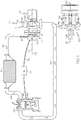
- FIG. 1 is a schematic view of an example e-charger 100 of the present disclosure.
- the e-charger 100 may include an e-charger housing assembly 101 and a shaft 103.
- the shaft 103 is configured to rotate within the e-charger housing assembly 101 about an axis 105 of rotation.
- a compressor wheel 104 may be mounted on the shaft 103.
- the e-charger 100 may also include an electric motor 108 that is configured to rotate the shaft 103 and compressor wheel 104. Accordingly, the compressor wheel 104 may receive an inlet air flow 113 and output a pressurized air stream 115 to a downstream component.
- the e-charger 100 may be provided within a vehicle. Additionally, in some embodiments, the e-charger 100 may be incorporated in a vehicle that includes a turbocharger 112.
- the turbocharger 112 may be conventional and may include a turbocharger housing 114 and a rotor 116.
- the rotor 116 is configured to rotate within the turbocharger housing 114 about an axis of rotor rotation 118.
- the turbocharger 112 includes a turbine section 119 configured to circumferentially receive a high-pressure and high-temperature exhaust gas stream 130 from an engine (e.g., from an exhaust manifold 132 of an internal combustion engine 134 or other type of engine).
- a turbine wheel 126 (and thus the rotor 116) is driven in rotation around the axis of rotor rotation 118 by the high-pressure and high-temperature exhaust gas stream 130, which becomes a lower-pressure and lower-temperature exhaust gas stream 136 that is released into a downstream exhaust pipe 138.
- the turbocharger 112 also includes a compressor section 121 with a compressor wheel 128 that is driven in rotation by the exhaust-gas driven turbine wheel 126.
- the compressor wheel 128 is configured to compress received input air 140 into a pressurized air stream 142. Due to the compression process, the pressurized air stream 142 is characterized by an increased temperature, over that of the input air 140.
- the air stream 142 may be channeled through an air cooler 144 (i.e., an intercooler), such as a convectively cooled charge air cooler.
- the air cooler 144 may be configured to dissipate heat from the air stream 142, increasing its density.
- the resulting cooled and pressurized air stream 146 is channeled into an intake manifold 148 of the internal combustion engine 134, or alternatively, into a subsequent-stage, in-series compressor.
- the operation of the system may be controlled by an ECU 150 (engine control unit) that connects to the remainder of the system via communication connections 152.
- the e-charger 100 may be disposed upstream of the turbocharger 112.
- the air stream 115 output from the e-charger 100 may mix with the exhaust gas stream 130 and/or otherwise provide air input to the turbine section 119 to turn the turbine wheel 126 and, thus, rotate the compressor wheel 128 of the turbocharger 112.
- the e-charger 100 may be incorporated differently within the vehicle without departing from the scope of the present disclosure.
- the e-charger 100 may be disposed downstream of the turbocharger 112 in some embodiments. In both cases, the e-charger 100 may feed air to the engine 134.
- the e-charger 100 may reduce transient time and turbo lag.
- the e-charger 100 may also provide benefits, such as reduced emissions, improved fuel efficiency, etc.
- the size of the turbocharger 112 may be reduced due to the inclusion of the e-charger 100.
- the e-charger 100 may be incorporated in a system that does not include a turbocharger 112.
- the e-charger 100 may be configured to feed air to a fuel cell of a vehicle.
- e-charger as used herein is to be interpreted broadly, for example, to include devices with an electrically driven compressor wheel regardless of where the e-charger is incorporated, the type of system in which the e-charger is incorporated, etc. It will also be appreciated that the e-charger of the present disclosure may also be referred to as an electrically driven compressor assembly. Also, the e-charger of the present disclosure may be configured as an electric supercharger, as a hybrid turbocharger, as an e-boost device, or other related component.
- the e-charger 100 may generally include the housing assembly 101, the shaft 103, the compressor wheel 104, and the electric motor 108.
- the shaft 103 may be substantially cylindrical and may include a first end 154, a second end 156, and an intermediate segment 157 extending between the first and second ends 154, 156.
- the compressor wheel 104 may be fixed to the shaft 103 and supported thereon adjacent the first end 154.
- the compressor wheel 104 may include a plurality of radially-extending blades 158.
- the electric motor 108 may include a rotor 160.
- the rotor 160 may be fixed to the intermediate segment 157 of the shaft 103. Accordingly, the rotor 160 and the shaft 103 may rotate as a unit about the axis 105 of rotation.
- the electric motor 108 may also include a stator 162 as shown in FIG. 3 . (The stator 162 is hidden in FIG. 2 to better illustrate other components.)
- the stator 162 may be cylindrical and hollow such that the intermediate segment 157 of the shaft 103 and the rotor 160 are received within the stator 162.
- the electric motor 108 may further include an electric module 164.
- the electric module 164 may include electrical equipment, such as a converter, circuitry, a controller for the electric motor 108, and/or other components. Thus, during operation, the electric module 164 may control the electric motor 108 such that the shaft 103 and the rotor 160 rotate about the axis 105 of rotation relative to the stator 162 in order to drivingly rotate the compressor wheel 104.
- the housing assembly 101 may include a number of components that are assembled together to at least partially house, surround, enclose, and/or encapsulate the compressor wheel 104, the shaft 103, and the electric motor 108.
- the housing assembly 101 may be configured to provide certain advantages with regards to manufacturability and/or other factors as will be discussed in detail below.
- the housing assembly 101 may generally include a compressor section 166, which houses the compressor wheel 104.
- the housing assembly 101 may also generally include an e-module section 168, which houses the electric module 164.
- the housing assembly 101 may generally include a motor section 170, which houses the electric motor 108.
- the compressor section 166 of the housing assembly 101 may include a volute member 172.
- the volute member 172 may include an inlet 173 that may be directed along the axis 105.
- the volute member 172 may also include an outlet (not shown) which provides air along the air stream 115 ( FIG. 1 ).
- the volute member 172 may further include an interior surface 175 with a volute shape extending circumferentially about the axis 105. During operation of the e-charger 100, the interior surface 175 may cooperate with the blades 158 of the compressor wheel 104 to compress air along the air stream 115.
- the volute member 172 may be fixed on one end of the motor section 170 of the housing assembly 101. Accordingly, the volute member 172 and the end of the motor section 170 may cooperate to house the compressor wheel 104 and the first end 154 of the shaft 103.
- the e-module section 168 may be fixed on an opposite end of the motor section 170.
- the e-module section 168 may include a shell 174 and an end cap 176.
- the shell 174 may be cylindrical and hollow with a first end 178 and a second end 180.
- the first end 178 may be fixed to the motor section 170.
- the end cap 176 may be disc-shaped and may be fixed to the second end 180 of the shell 174 to close off the second end 180. Accordingly, the shell 174, the end cap 176, and the end of the motor section 170 may cooperate to substantially encapsulate the electric module 164.
- the motor section 170 of the housing assembly 101 may include an outer shell member 182, a first member 184, a second member 186, and a third member 188.
- the outer shell member 182 may cooperate with the volute member 172 and the e-module section 168 to define the exterior of the e-charger 100.
- the first member 184 may be referred to as a "stator housing” because it substantially surrounds the stator 162.
- the second member 186 and the third member 188 may be referred to as "bearing plates" or "end caps”.
- the first member 184, the second member 186, and the third member 188 may cooperate to substantially encapsulate the rotor 160 and the stator 162.
- the outer shell member 182 may be generally cylindrical and may be hollow so as to encircle the axis 105 in the circumferential direction.
- the outer shell member 182 may include a first end 190 and a second end 192.
- the first end 190 may be fixed to the volute member 172.
- the volute member 172 may radially overlap the outer diameter surface of the first end 190 of the outer shell member 182.
- the second end 192 of the outer shell member 182 may be fixed to the e-module section 168.
- the shell 174 of the e-module section 168 may radially overlap the outer diameter surface of the second end 192 of the outer shell member 182.
- the first member 184 of the housing assembly 101 may also be generally cylindrical and may be hollow. Accordingly, the first member 184 may encircle the axis 105 in the circumferential direction and may extend longitudinally along the axis 105.
- the first member 184 may include a first end 194, a second end 196, and an intermediate portion 198 that extends along the axis 105 between the first and second ends 194, 196.
- the first end 194 of the first member 184 may be an annular flange that projects in a longitudinal direction along the axis 105 from a front vertical face 200 of the intermediate portion 198.
- the first end 194 may include an inner diameter surface 202, which faces radially inward, and an outer diameter surface 204, which faces radially outward.
- the second end 196 of the first member 184 may be an annular flange that projects from a rear vertical face 206 of the intermediate portion 198.
- the second end 196 may include an inner diameter surface 208, which faces radially inward, and an outer diameter surface 210, which faces radially outward.
- the second member 186 of the housing assembly 101 may be generally disc-shaped. As shown in FIG. 3 , the second member 186 may include a central opening 212 that is substantially centered on the axis 105. The second member 186 may also include an outer face 214 that faces the compressor wheel 128 and an inner face 216 that faces the electric motor 108. Moreover, as shown in FIGS. 3 and 4 , the second member 186 may include a first outer portion 218 that is supported against the volute member 172 and the outer shell member 182. In some embodiments, the housing assembly 101 may also include a ring 213 that is disposed between the first outer portion 218 and the outer shell member 182.
- the second member 186 may further include a second outer portion 220 that is disposed adjacent the first end 194 of the first member 184 of the housing assembly 101 and the front vertical face 200 of the first member 184 of the housing assembly 101.
- the second outer portion 220 may be radially overlapped and received within the open first end 194 of the first member 184 of the housing assembly 101. Accordingly, the second member 186 may allow passage of the first end 154 of the shaft 103 from the motor section 170 to the compressor section 166 of the housing assembly 101.
- the second member 186 may also support the shaft 103 for rotation within the housing assembly 101 as will be discussed in detail below.
- the second member 186 may act as a barrier between the compressor wheel 104 and the electric motor 108.
- the third member 188 of the housing assembly 101 may be generally disc-shaped.
- the third member 188 may include a central opening 222 that is substantially centered on the axis 105.
- the third member 188 may also include an outer face 224 that faces the electric module 164 and an inner face 226 that faces the electric motor 108.
- the third member 188 may include a first outer portion 228 that is supported against the outer shell member 182.
- the housing assembly may also include a ring 229 that is disposed between the first outer portion 228 and the outer shell member 182.
- the third member 188 may include a second outer portion 230 that is disposed adjacent the second end 196 of the first member 184 of the housing assembly 101.
- the second outer portion 230 may be radially overlapped and received within the open second end 196 of the first member 184 of the housing assembly 101.
- the third member 188 may also support the shaft 103 for rotation within the housing assembly 101 as will be discussed in detail below. Moreover, the third member 188 may act as a barrier between the electric motor 108 and the electric module 164.
- the housing assembly 101 may support the shaft 103 and the rotor 160 for rotation about the axis 105.
- the e-charger 100 may include a first bearing 232 and a second bearing 234.
- the first bearing 232 may be disposed in the central opening 212 of the second member 186 and may include an outer race that is fixed to the second member 186, an inner race that is fixed to the intermediate segment 157 of the shaft 103, and a plurality of ball bearings disposed between the inner and outer races.
- the second bearing 234 may be similar, except it may be disposed in the central opening 222 of the third member 188, with its outer race fixed to the third member 188 and its inner race fixed to the intermediate segment 157 of the shaft 103.
- first bearing 232 and/or the second bearing 234 may be greasepack ball bearings. These bearings may provide cost savings in some embodiments. Also, these types of bearings can be packaged within relatively compact spaces within the e-charger.
- the e-charger 100 may include at least one coolant flowpath therethrough.
- the e-charger 100 may include a port 236, a front groove 238, and a rear groove 240.
- the port 236 may extend through the outer shell member 182 and allow coolant flow into or out of the e-charger 100.
- the front groove 238 may extend radially into the second member 186, separating the first and second outer portions 218, 220 of the second member 186.
- the rear groove 240 may extend radially into the third member 188, separating the first and second outer portions 228, 230. Accordingly, coolant may flow between the port 236, the front groove 238, and the rear groove 240 to provide a cooling effect for the e-charger 100.
- the e-charger 100 may include a number of seals, such as O-rings 242.
- the O-rings 242 may be conventional and may be provided between different members of the housing assembly 101 to prevent leakage of the coolant, to prevent intrusion of foreign materials, and/or to otherwise provide a seal between different members of the e-charger 100.
- the e-charger 100 may also include a damping system 250.
- the damping system 250 may include a first dampener 252 and a second dampener 254 in some embodiments.
- the first dampener 252 and the second dampener 254 may be substantially similar to each other except as noted below.
- the first dampener 252 may be substantially annular. As shown in FIG. 5 , the first dampener 252 may be a unitary (i.e., one-piece) member that extends annularly and continuously about the axis 105 of rotation As shown in FIGS. 2 and 4 , the first dampener 252 may include an inner radial surface 256 and an outer radial surface 258. The first dampener 252 may further include an outer edge 260 and an inner edge 262.
- the inner radial surface 256 and/or the outer radial surface 258 may be uneven.
- the inner radial surface 256 and the outer radial surface 258 may be wavy, bumpy, and/or corrugated in some embodiments.
- the inner radial surface 256 may have alternating peaks and troughs as shown in FIG. 2 .
- the outer radial surface 258 may similarly include alternating peaks and troughs.
- the peaks and troughs of the inner radial surface 256 may be inverse to those of the peaks and troughs of the outer radial surface 258.
- a thickness of the dampener 252 (measured between the inner radial surface 256 and the outer radial surface 258) may be substantially constant and continuous in the circumferential direction about the axis 105.
- the first dampener 252 may be made out of a metallic material in some embodiments. Also, the first dampener 252 may be resilient and flexible. As such, the dampener 252 may elastically deform (e.g., between a neutral first position shown in the Figures and a second deformed position). In some embodiments, the inner radial surface 256 and/or the outer radial surface 258 may deform when the first dampener 252 is subjected to sufficient force. For example, the waves, bumps, and/or corrugations may elastically deflect when the first dampener 252 is under a sufficient load.
- the first dampener 252 may be disposed between the first member 184 and the second member 186 of the housing assembly 101. More specifically, as shown in FIG. 5 , portions of the inner radial surface 256 of the first dampener 252 may abut against an opposing outer diameter surface 288 of the second outer portion 220 of the second member 186. Also, portions of the outer radial surface 258 may abut against the opposing inner diameter surface 202 of the first end 194 of the first member 184. Furthermore, as shown in FIG. 4 , the outer edge 260 may abut against an opposing shoulder 290 of the second outer portion 220. Additionally, the inner edge 262 may abut against the opposing front vertical face 200 of the first member 184 of the housing assembly 101.
- the first dampener 252 may provide dampening of forces (e.g., vibrational and other forces) that transfer between the first member 184 and the second member 186 of the housing assembly 101.
- the first dampener 252 may resiliently deflect in order to dampen and reduce these forces.
- the first dampener 252 may provide dampening to forces that are directed radially and/or axially with respect to the axis 105.
- the second dampener 254 may be substantially similar to the first dampener 252 except that the second dampener 254 may be disposed between the first member 184 and the third member 188. Specifically, as shown in FIG. 3 , the second dampener 254 may abut radially against the second outer portion 230 of the third member 188 and the second end 196 of the first member 184. Also, the second dampener 254 may abut axially against the first member 184 and the third member 188. Accordingly, the second dampener 254 may provide dampening to radial and/or axial forces that transfer between the first member 184 and the third member 188.
- the damping system 250 of the present disclosure may reduce radial and axial loads of the e-charger 100.
- the damping system 250 may also increase the operating life of the e-charger, for example, because loading on the bearings 232, 234 may be reduced.
- the bearings 232, 234 included in the e-charger 100 may be relatively cost-effective and compact bearings, such as greasepack ball bearings.
- the dampeners 252, 254 may compensate for any bearing misalignment.
- the dampeners 252, 254 may decrease vibration of the stator 162.
- the temperature of the damping system 250 may be controlled, for example, by the coolant flowing within the nearby coolant grooves 238, 240.
- the damping system 250 may allow the e-charger 100 to be more compact than conventional e-chargers. Moreover, the damping system 250 may provide increased manufacturing efficiency. For example, the dampeners 252, 254 may be relatively simple to assemble within the housing assembly 101. Thus, the e-charger 100 may be manufactured and assembled in an efficient manner.
Abstract
Description
- The present disclosure generally relates to an electrically driven compressor assembly such as an e-charger, and more particularly relates to a damping system for an e-charger.
- Some vehicles include a turbocharger, supercharger and/or other devices for boosting the performance of an internal combustion engine. More specifically, these devices can increase the engine's efficiency and power output by forcing extra air into the combustion chamber of the engine.
- In some cases, the vehicle may include an electrically driven compressor, or e-charger, for these purposes. However, conventional e-chargers can be bulky, cost prohibitive, and/or may present other issues.
- Thus, it is desirable to provide an e-charger that is more compact than conventional e-chargers. Also, it is desirable to provide an e-charger that provides cost savings compared to conventional e-chargers. Other desirable features and characteristics of the present disclosure will become apparent from the subsequent detailed description and the appended claims, taken in conjunction with the accompanying drawings and this background discussion.
- In one embodiment, an electrically driven compressor assembly is disclosed that includes a shaft and a compressor wheel that is supported on the shaft. The compressor assembly also includes an electric motor with a stator and a rotor. The electric motor is configured to rotate the shaft and the compressor wheel. The compressor assembly additionally includes a housing assembly configured to house the stator, the rotor, and at least part of the shaft. The housing assembly includes a first member and a second member. Moreover, the compressor assembly includes a dampener disposed between the first member and the second member of the housing assembly. The dampener is configured to elastically deform to provide dampening of a force transferred between the first member and the second member of the housing assembly.
- In another embodiment, a method of manufacturing an electrically driven compressor assembly is disclosed. The method includes providing a first member and a second member of a housing assembly. The method also includes supporting a shaft on the first member for rotation relative to the first member. A compressor wheel is supported on the shaft. The method further includes housing an electric motor within the housing assembly between the first member and the second member. The electric motor is configured to rotate the shaft and the compressor wheel. Moreover, the method includes attaching the first member and the second member together with a dampener between the first member and the second member. The dampener is configured to elastically deform to provide dampening of a force transferred between the first member and the second member of the housing assembly.
- In an additional embodiment, an e-charger is disclosed that includes a shaft and a compressor wheel with a plurality of blades. The compressor wheel is fixed for rotation on the shaft for rotation about an axis. The e-charger also includes an electric motor with a stator and a rotor. The rotor is fixed to the shaft. The stator receives the rotor and a portion of the shaft. The electric motor is configured to rotate the shaft and the compressor wheel about the axis. Additionally, the e-charger includes a housing assembly with a compressor section and a motor section. The compressor section is configured to house the compressor wheel, and the motor section is configured to house the stator and the rotor. The motor section includes a first member and a second member. The shaft extends through the second member to be received in the compressor section and the motor section. Also, the e-charger includes a bearing that is attached to the second member of the housing assembly and that is attached to the shaft. The bearing supports the shaft for rotation relative to the second member about the axis. Furthermore, the e-charger includes a dampener disposed between the first member and the second member of the housing assembly. The dampener is configured to elastically deform to provide dampening of a force transferred between the first member and the second member of the housing assembly.
- The present disclosure will hereinafter be described in conjunction with the following drawing figures, wherein like numerals denote like elements, and wherein:
-
FIG. 1 is a schematic view of a vehicle engine system, which includes an e-charger according to example embodiments of the present disclosure; -
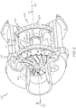
FIG. 2 is a perspective view of the e-charger ofFIG. 1 with some features hidden to show internal components of the e-charger; -
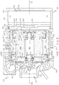
FIG. 3 is a cross sectional view of the e-charger taken along the line 3-3 ofFIG. 2 ; -
FIG. 4 is a detail section view of a portion of the e-charger indicated inFIG. 3 ; and -
FIG. 5 is a cross sectional view of the turbocharger taken along the line 5-5 ofFIG. 3 . - The following detailed description is merely exemplary in nature and is not intended to limit the present disclosure or the application and uses of the present disclosure. Furthermore, there is no intention to be bound by any theory presented in the preceding background or the following detailed description.
- Broadly, example embodiments disclosed herein include a damping system of an electrically powered compressor (i.e., an e-charger). One or more dampeners may be provided for damping forces translating through the e-charger and/or supporting structure(s).
- In particular, the dampener may be resiliently deformable. The dampener may also include one or more surface features, shapes, dimensions, materials, and/or other elements that provide improved dampening. Additionally, the dampener may be incorporated within the damping system in ways that improve its damping function. For example, the dampener may be disposed between different members of a housing assembly, and the dampener may be supported by these members to provide effective damping of the forces transferring through the housing assembly. Furthermore, the damping system may allow certain types of bearings to be incorporated in the e-charger for added benefit. Moreover, the damping system may provide manufacturing efficiencies due to one or more features of the present disclosure. Additional details of the present disclosure will be discussed below.
-
FIG. 1 is a schematic view of an example e-charger 100 of the present disclosure. Generally, thee-charger 100 may include ane-charger housing assembly 101 and ashaft 103. Theshaft 103 is configured to rotate within thee-charger housing assembly 101 about anaxis 105 of rotation. Acompressor wheel 104 may be mounted on theshaft 103. Thee-charger 100 may also include anelectric motor 108 that is configured to rotate theshaft 103 andcompressor wheel 104. Accordingly, thecompressor wheel 104 may receive aninlet air flow 113 and output a pressurizedair stream 115 to a downstream component. - In some embodiments, the e-charger 100 may be provided within a vehicle. Additionally, in some embodiments, the e-charger 100 may be incorporated in a vehicle that includes a
turbocharger 112. - The
turbocharger 112 may be conventional and may include aturbocharger housing 114 and arotor 116. Therotor 116 is configured to rotate within theturbocharger housing 114 about an axis ofrotor rotation 118. - The
turbocharger 112 includes aturbine section 119 configured to circumferentially receive a high-pressure and high-temperatureexhaust gas stream 130 from an engine (e.g., from anexhaust manifold 132 of aninternal combustion engine 134 or other type of engine). A turbine wheel 126 (and thus the rotor 116) is driven in rotation around the axis ofrotor rotation 118 by the high-pressure and high-temperatureexhaust gas stream 130, which becomes a lower-pressure and lower-temperatureexhaust gas stream 136 that is released into adownstream exhaust pipe 138. - The
turbocharger 112 also includes a compressor section 121 with acompressor wheel 128 that is driven in rotation by the exhaust-gas driventurbine wheel 126. Thecompressor wheel 128 is configured to compress receivedinput air 140 into apressurized air stream 142. Due to the compression process, thepressurized air stream 142 is characterized by an increased temperature, over that of theinput air 140. - The
air stream 142 may be channeled through an air cooler 144 (i.e., an intercooler), such as a convectively cooled charge air cooler. Theair cooler 144 may be configured to dissipate heat from theair stream 142, increasing its density. The resulting cooled andpressurized air stream 146 is channeled into anintake manifold 148 of theinternal combustion engine 134, or alternatively, into a subsequent-stage, in-series compressor. The operation of the system may be controlled by an ECU 150 (engine control unit) that connects to the remainder of the system viacommunication connections 152. - As represented schematically in
FIG. 1 , the e-charger 100 may be disposed upstream of theturbocharger 112. For example, theair stream 115 output from the e-charger 100 may mix with theexhaust gas stream 130 and/or otherwise provide air input to theturbine section 119 to turn theturbine wheel 126 and, thus, rotate thecompressor wheel 128 of theturbocharger 112. However, it will be appreciated that the e-charger 100 may be incorporated differently within the vehicle without departing from the scope of the present disclosure. For example, the e-charger 100 may be disposed downstream of theturbocharger 112 in some embodiments. In both cases, the e-charger 100 may feed air to theengine 134. The e-charger 100 may reduce transient time and turbo lag. The e-charger 100 may also provide benefits, such as reduced emissions, improved fuel efficiency, etc. Also, the size of theturbocharger 112 may be reduced due to the inclusion of the e-charger 100. - Also, it will be appreciated that the e-charger 100 may be incorporated in a system that does not include a
turbocharger 112. For example, in additional embodiments, the e-charger 100 may be configured to feed air to a fuel cell of a vehicle. - In addition, it will be appreciated that the term "e-charger" as used herein is to be interpreted broadly, for example, to include devices with an electrically driven compressor wheel regardless of where the e-charger is incorporated, the type of system in which the e-charger is incorporated, etc. It will also be appreciated that the e-charger of the present disclosure may also be referred to as an electrically driven compressor assembly. Also, the e-charger of the present disclosure may be configured as an electric supercharger, as a hybrid turbocharger, as an e-boost device, or other related component.
- Referring now to
FIGS. 2 and3 , the e-charger 100 will be discussed in greater detail according to example embodiments. As mentioned above, the e-charger 100 may generally include thehousing assembly 101, theshaft 103, thecompressor wheel 104, and theelectric motor 108. - The
shaft 103 may be substantially cylindrical and may include afirst end 154, asecond end 156, and anintermediate segment 157 extending between the first and second ends 154, 156. Thecompressor wheel 104 may be fixed to theshaft 103 and supported thereon adjacent thefirst end 154. Thecompressor wheel 104 may include a plurality of radially-extendingblades 158. - The
electric motor 108 may include arotor 160. Therotor 160 may be fixed to theintermediate segment 157 of theshaft 103. Accordingly, therotor 160 and theshaft 103 may rotate as a unit about theaxis 105 of rotation. Theelectric motor 108 may also include astator 162 as shown inFIG. 3 . (Thestator 162 is hidden inFIG. 2 to better illustrate other components.) Thestator 162 may be cylindrical and hollow such that theintermediate segment 157 of theshaft 103 and therotor 160 are received within thestator 162. - The
electric motor 108 may further include anelectric module 164. Theelectric module 164 may include electrical equipment, such as a converter, circuitry, a controller for theelectric motor 108, and/or other components. Thus, during operation, theelectric module 164 may control theelectric motor 108 such that theshaft 103 and therotor 160 rotate about theaxis 105 of rotation relative to thestator 162 in order to drivingly rotate thecompressor wheel 104. - The
housing assembly 101 may include a number of components that are assembled together to at least partially house, surround, enclose, and/or encapsulate thecompressor wheel 104, theshaft 103, and theelectric motor 108. Thehousing assembly 101 may be configured to provide certain advantages with regards to manufacturability and/or other factors as will be discussed in detail below. - As shown in
FIG. 3 , thehousing assembly 101 may generally include acompressor section 166, which houses thecompressor wheel 104. Thehousing assembly 101 may also generally include ane-module section 168, which houses theelectric module 164. Also, thehousing assembly 101 may generally include amotor section 170, which houses theelectric motor 108. - The
compressor section 166 of thehousing assembly 101 may include avolute member 172. Thevolute member 172 may include aninlet 173 that may be directed along theaxis 105. Thevolute member 172 may also include an outlet (not shown) which provides air along the air stream 115 (FIG. 1 ). Thevolute member 172 may further include aninterior surface 175 with a volute shape extending circumferentially about theaxis 105. During operation of the e-charger 100, theinterior surface 175 may cooperate with theblades 158 of thecompressor wheel 104 to compress air along theair stream 115. Thevolute member 172 may be fixed on one end of themotor section 170 of thehousing assembly 101. Accordingly, thevolute member 172 and the end of themotor section 170 may cooperate to house thecompressor wheel 104 and thefirst end 154 of theshaft 103. - As shown in
FIG. 3 , thee-module section 168 may be fixed on an opposite end of themotor section 170. Thee-module section 168 may include ashell 174 and anend cap 176. Theshell 174 may be cylindrical and hollow with afirst end 178 and asecond end 180. Thefirst end 178 may be fixed to themotor section 170. Theend cap 176 may be disc-shaped and may be fixed to thesecond end 180 of theshell 174 to close off thesecond end 180. Accordingly, theshell 174, theend cap 176, and the end of themotor section 170 may cooperate to substantially encapsulate theelectric module 164. - The
motor section 170 of thehousing assembly 101 may include anouter shell member 182, afirst member 184, asecond member 186, and athird member 188. In some embodiments, theouter shell member 182 may cooperate with thevolute member 172 and thee-module section 168 to define the exterior of the e-charger 100. Also, in some embodiments, thefirst member 184 may be referred to as a "stator housing" because it substantially surrounds thestator 162. Furthermore, thesecond member 186 and thethird member 188 may be referred to as "bearing plates" or "end caps". In some embodiments, thefirst member 184, thesecond member 186, and thethird member 188 may cooperate to substantially encapsulate therotor 160 and thestator 162. - In some embodiments, the
outer shell member 182 may be generally cylindrical and may be hollow so as to encircle theaxis 105 in the circumferential direction. Theouter shell member 182 may include afirst end 190 and asecond end 192. Thefirst end 190 may be fixed to thevolute member 172. For example, as shown inFIG. 3 , thevolute member 172 may radially overlap the outer diameter surface of thefirst end 190 of theouter shell member 182. Thesecond end 192 of theouter shell member 182 may be fixed to thee-module section 168. For example, theshell 174 of thee-module section 168 may radially overlap the outer diameter surface of thesecond end 192 of theouter shell member 182. - The
first member 184 of thehousing assembly 101 may also be generally cylindrical and may be hollow. Accordingly, thefirst member 184 may encircle theaxis 105 in the circumferential direction and may extend longitudinally along theaxis 105. Thefirst member 184 may include afirst end 194, asecond end 196, and anintermediate portion 198 that extends along theaxis 105 between the first and second ends 194, 196. - As shown in
FIGS. 3 and4 , thefirst end 194 of thefirst member 184 may be an annular flange that projects in a longitudinal direction along theaxis 105 from a frontvertical face 200 of theintermediate portion 198. Thefirst end 194 may include aninner diameter surface 202, which faces radially inward, and anouter diameter surface 204, which faces radially outward. - As shown in
FIG. 3 , thesecond end 196 of thefirst member 184 may be an annular flange that projects from a rearvertical face 206 of theintermediate portion 198. Thesecond end 196 may include aninner diameter surface 208, which faces radially inward, and anouter diameter surface 210, which faces radially outward. - The
second member 186 of thehousing assembly 101 may be generally disc-shaped. As shown inFIG. 3 , thesecond member 186 may include acentral opening 212 that is substantially centered on theaxis 105. Thesecond member 186 may also include anouter face 214 that faces thecompressor wheel 128 and aninner face 216 that faces theelectric motor 108. Moreover, as shown inFIGS. 3 and4 , thesecond member 186 may include a firstouter portion 218 that is supported against thevolute member 172 and theouter shell member 182. In some embodiments, thehousing assembly 101 may also include aring 213 that is disposed between the firstouter portion 218 and theouter shell member 182. Thesecond member 186 may further include a secondouter portion 220 that is disposed adjacent thefirst end 194 of thefirst member 184 of thehousing assembly 101 and the frontvertical face 200 of thefirst member 184 of thehousing assembly 101. In some embodiments, the secondouter portion 220 may be radially overlapped and received within the openfirst end 194 of thefirst member 184 of thehousing assembly 101. Accordingly, thesecond member 186 may allow passage of thefirst end 154 of theshaft 103 from themotor section 170 to thecompressor section 166 of thehousing assembly 101. Thesecond member 186 may also support theshaft 103 for rotation within thehousing assembly 101 as will be discussed in detail below. Moreover, thesecond member 186 may act as a barrier between thecompressor wheel 104 and theelectric motor 108. - The
third member 188 of thehousing assembly 101 may be generally disc-shaped. Thethird member 188 may include acentral opening 222 that is substantially centered on theaxis 105. Thethird member 188 may also include anouter face 224 that faces theelectric module 164 and aninner face 226 that faces theelectric motor 108. Moreover, thethird member 188 may include a firstouter portion 228 that is supported against theouter shell member 182. In some embodiments, the housing assembly may also include aring 229 that is disposed between the firstouter portion 228 and theouter shell member 182. Additionally, thethird member 188 may include a second outer portion 230 that is disposed adjacent thesecond end 196 of thefirst member 184 of thehousing assembly 101. In some embodiments, the second outer portion 230 may be radially overlapped and received within the opensecond end 196 of thefirst member 184 of thehousing assembly 101. Thethird member 188 may also support theshaft 103 for rotation within thehousing assembly 101 as will be discussed in detail below. Moreover, thethird member 188 may act as a barrier between theelectric motor 108 and theelectric module 164. - As mentioned, the
housing assembly 101 may support theshaft 103 and therotor 160 for rotation about theaxis 105. For example, as shown inFIG. 3 , the e-charger 100 may include afirst bearing 232 and asecond bearing 234. Thefirst bearing 232 may be disposed in thecentral opening 212 of thesecond member 186 and may include an outer race that is fixed to thesecond member 186, an inner race that is fixed to theintermediate segment 157 of theshaft 103, and a plurality of ball bearings disposed between the inner and outer races. Thesecond bearing 234 may be similar, except it may be disposed in thecentral opening 222 of thethird member 188, with its outer race fixed to thethird member 188 and its inner race fixed to theintermediate segment 157 of theshaft 103. - In some embodiments, the
first bearing 232 and/or thesecond bearing 234 may be greasepack ball bearings. These bearings may provide cost savings in some embodiments. Also, these types of bearings can be packaged within relatively compact spaces within the e-charger. - Furthermore, the e-charger 100 may include at least one coolant flowpath therethrough. For example, as shown in
FIG. 3 , the e-charger 100 may include aport 236, afront groove 238, and arear groove 240. Theport 236 may extend through theouter shell member 182 and allow coolant flow into or out of the e-charger 100. Thefront groove 238 may extend radially into thesecond member 186, separating the first and secondouter portions second member 186. Therear groove 240 may extend radially into thethird member 188, separating the first and secondouter portions 228, 230. Accordingly, coolant may flow between theport 236, thefront groove 238, and therear groove 240 to provide a cooling effect for the e-charger 100. - Additionally, the e-charger 100 may include a number of seals, such as O-
rings 242. The O-rings 242 may be conventional and may be provided between different members of thehousing assembly 101 to prevent leakage of the coolant, to prevent intrusion of foreign materials, and/or to otherwise provide a seal between different members of the e-charger 100. - As shown in
FIGS. 2 ,3 , and4 , the e-charger 100 may also include a dampingsystem 250. The dampingsystem 250 may include afirst dampener 252 and asecond dampener 254 in some embodiments. Thefirst dampener 252 and thesecond dampener 254 may be substantially similar to each other except as noted below. - The
first dampener 252 may be substantially annular. As shown inFIG. 5 , thefirst dampener 252 may be a unitary (i.e., one-piece) member that extends annularly and continuously about theaxis 105 of rotation As shown inFIGS. 2 and4 , thefirst dampener 252 may include an innerradial surface 256 and an outerradial surface 258. Thefirst dampener 252 may further include anouter edge 260 and aninner edge 262. - In some embodiments, the inner
radial surface 256 and/or the outerradial surface 258 may be uneven. For example, the innerradial surface 256 and the outerradial surface 258 may be wavy, bumpy, and/or corrugated in some embodiments. As such, the innerradial surface 256 may have alternating peaks and troughs as shown inFIG. 2 . The outerradial surface 258 may similarly include alternating peaks and troughs. The peaks and troughs of the innerradial surface 256 may be inverse to those of the peaks and troughs of the outerradial surface 258. Also, in some embodiments, a thickness of the dampener 252 (measured between the innerradial surface 256 and the outer radial surface 258) may be substantially constant and continuous in the circumferential direction about theaxis 105. - The
first dampener 252 may be made out of a metallic material in some embodiments. Also, thefirst dampener 252 may be resilient and flexible. As such, thedampener 252 may elastically deform (e.g., between a neutral first position shown in the Figures and a second deformed position). In some embodiments, the innerradial surface 256 and/or the outerradial surface 258 may deform when thefirst dampener 252 is subjected to sufficient force. For example, the waves, bumps, and/or corrugations may elastically deflect when thefirst dampener 252 is under a sufficient load. - The
first dampener 252 may be disposed between thefirst member 184 and thesecond member 186 of thehousing assembly 101. More specifically, as shown inFIG. 5 , portions of the innerradial surface 256 of thefirst dampener 252 may abut against an opposingouter diameter surface 288 of the secondouter portion 220 of thesecond member 186. Also, portions of the outerradial surface 258 may abut against the opposinginner diameter surface 202 of thefirst end 194 of thefirst member 184. Furthermore, as shown inFIG. 4 , theouter edge 260 may abut against an opposingshoulder 290 of the secondouter portion 220. Additionally, theinner edge 262 may abut against the opposing frontvertical face 200 of thefirst member 184 of thehousing assembly 101. - Accordingly, the
first dampener 252 may provide dampening of forces (e.g., vibrational and other forces) that transfer between thefirst member 184 and thesecond member 186 of thehousing assembly 101. Thefirst dampener 252 may resiliently deflect in order to dampen and reduce these forces. Also, in some embodiments, thefirst dampener 252 may provide dampening to forces that are directed radially and/or axially with respect to theaxis 105. - The
second dampener 254 may be substantially similar to thefirst dampener 252 except that thesecond dampener 254 may be disposed between thefirst member 184 and thethird member 188. Specifically, as shown inFIG. 3 , thesecond dampener 254 may abut radially against the second outer portion 230 of thethird member 188 and thesecond end 196 of thefirst member 184. Also, thesecond dampener 254 may abut axially against thefirst member 184 and thethird member 188. Accordingly, thesecond dampener 254 may provide dampening to radial and/or axial forces that transfer between thefirst member 184 and thethird member 188. - Accordingly, the damping
system 250 of the present disclosure may reduce radial and axial loads of the e-charger 100. The dampingsystem 250 may also increase the operating life of the e-charger, for example, because loading on thebearings bearings dampeners dampeners stator 162. The temperature of the dampingsystem 250 may be controlled, for example, by the coolant flowing within thenearby coolant grooves system 250 may allow the e-charger 100 to be more compact than conventional e-chargers. Moreover, the dampingsystem 250 may provide increased manufacturing efficiency. For example, thedampeners housing assembly 101. Thus, the e-charger 100 may be manufactured and assembled in an efficient manner. - While at least one exemplary embodiment has been presented in the foregoing detailed description, it should be appreciated that a vast number of variations exist. It should also be appreciated that the exemplary embodiment or exemplary embodiments are only examples, and are not intended to limit the scope, applicability, or configuration of the present disclosure in any way. Rather, the foregoing detailed description will provide those skilled in the art with a convenient road map for implementing an exemplary embodiment of the present disclosure. It is understood that various changes may be made in the function and arrangement of elements described in an exemplary embodiment without departing from the scope of the present disclosure as set forth in the appended claims.
Claims (20)
- An electrically driven compressor assembly comprising:a shaft;a compressor wheel that is supported on the shaft;an electric motor with a stator and a rotor, the electric motor configured to rotate the shaft and the compressor wheel;a housing assembly configured to house the stator, the rotor, and at least part of the shaft, the housing assembly including a first member and a second member;a dampener disposed between the first member and the second member of the housing assembly, the dampener configured to elastically deform to provide dampening of a force transferred between the first member and the second member of the housing assembly.
- The compressor assembly of claim 1, wherein the dampener is configured to elastically deform between a first position and a second position;
wherein the dampener includes a surface that is uneven in the first position; and
wherein the surface is configured to deform as the dampener moves between the first position and second position. - The compressor assembly of claim 2, wherein the shaft is configured to rotate about an axis of rotation;
wherein the dampener extends in a circumferential direction about the axis of rotation, wherein the dampener includes an inner radial surface facing the axis of rotation and an outer radial surface facing away from the axis of rotation, and wherein at least one of the inner radial surface and the outer radial surface is uneven in the first position. - The compressor assembly of claim 3, wherein both the inner radial surface and the outer radial surface are uneven in the first position.
- The compressor assembly of claim 4, wherein the dampener has a thickness measured between the inner radial surface and the outer radial surface; and
wherein the thickness of the dampener is substantially constant along the circumferential direction. - The compressor assembly of claim 3, wherein the at least one of the inner radial surface and the outer radial surface includes a plurality of alternating peaks and troughs in the first position.
- The compressor assembly of claim 1, wherein the first member of the housing assembly includes a first surface;
wherein the second member of the housing assembly includes a second surface that faces opposite the first surface;
wherein the dampener abuts the first surface of the first member of the housing assembly; and
wherein the dampener abuts the second surface of the second member of the housing assembly. - The compressor assembly of claim 7, wherein the shaft is configured to rotate about an axis of rotation;
wherein the first surface faces substantially in a first radial direction relative to the axis of rotation;
wherein the second surface faces substantially in a second radial direction relative to the axis of rotation; and
wherein the first radial direction is opposite the second radial direction. - The compressor assembly of claim 8, wherein the dampener abuts a first face of the first member and abuts a second face of the second member; and
wherein the first face faces in a first longitudinal direction relative to the axis of rotation; and
wherein the second face faces in a second longitudinal direction relative to the axis of rotation. - The compressor assembly of claim 1, wherein the dampener is a unitary member that extends annularly and continuously about an axis of rotation of the shaft.
- The compressor assembly of claim 1, further comprising a bearing that supports rotation of the shaft relative to the second member of the housing assembly about an axis of rotation;
wherein the first member of the housing assembly extends in a circumferential direction about the axis of rotation and in a longitudinal direction along the axis of rotation to cover the rotor and the stator;
wherein the first member includes an open end; and
wherein the second member of the housing assembly covers the open end. - The compressor assembly of claim 11, wherein the bearing is a greasepack ball bearing.
- The compressor assembly of claim 11, wherein the second member is received within the open end of the first member.
- The compressor assembly of claim 1, wherein the dampener is a first dampener;
wherein the housing assembly includes a third member;
wherein the first member, the second member, and the third member cooperate to substantially encapsulate the rotor and the stator;
wherein the shaft is supported for rotation on the second member by a first bearing;
wherein the shaft is supported for rotation on the third member by a second bearing; and
further comprising a second dampener that is disposed between the first member and the third member, the second dampener configured to elastically deform to provide dampening of a force that is transferred between the first member and the third member of the housing assembly. - A method of manufacturing an electrically driven compressor assembly comprising:providing a first member and a second member of a housing assembly;supporting a shaft on the first member for rotation relative to the first member, a compressor wheel being supported on the shaft;housing an electric motor within the housing assembly between the first member and the second member, the electric motor configured to rotate the shaft and the compressor wheel; andattaching the first member and the second member together with a dampener between the first member and the second member, the dampener configured to elastically deform to provide dampening of a force transferred between the first member and the second member of the housing assembly.
- The method of claim 15, further comprising:abutting the dampener against a first surface of the first member; andabutting the dampener against a second surface of the second member, the second surface facing the first surface.
- The method of claim 16, wherein the shaft is configured to rotate about an axis of rotation;
wherein the first surface faces substantially in a first radial direction relative to the axis of rotation;
wherein the second surface faces substantially in a second radial direction relative to the axis of rotation; and
wherein the first radial direction is opposite the second radial direction. - The method of claim 17, further comprising:abutting the dampener against a first face of the first member; andabutting the dampener against a second face of the second member;wherein the first face faces in a first longitudinal direction relative to the axis of rotation; andwherein the second face faces in a second longitudinal direction relative to the axis of rotation.
- An e-charger comprising:a shaft;a compressor wheel with a plurality of blades, the compressor wheel being fixed for rotation on the shaft for rotation about an axis;an electric motor with a stator and a rotor, the rotor being fixed to the shaft, the stator receiving the rotor and a portion of the shaft, the electric motor configured to rotate the shaft and the compressor wheel about the axis;a housing assembly with a compressor section and a motor section, the compressor section configured to house the compressor wheel, the motor section configured to house the stator and the rotor, the motor section including a first member and a second member, the shaft extending through the second member to be received in the compressor section and the motor section;a bearing that is attached to the second member of the housing assembly and that is attached to the shaft, the bearing supporting the shaft for rotation relative to the second member about the axis; anda dampener disposed between the first member and the second member of the housing assembly, the dampener configured to elastically deform to provide dampening of a force transferred between the first member and the second member of the housing assembly.
- The e-charger of claim 19, wherein the bearing is a first bearing and the dampener is a first dampener;
wherein the housing assembly further includes a third member, wherein the first member, the second member, and the third member cooperate to substantially encapsulate the rotor and the stator;
further comprising a second bearing that is attached to the third member of the housing assembly and that is attached to the shaft, the bearing supporting the shaft for rotation relative to the third member about the axis; and
further comprising a second dampener that is disposed between the first member and the third member, the second dampener configured to elastically deform to provide dampening of a force that is transferred between the first member and the third member of the housing assembly.
Applications Claiming Priority (1)
| Application Number | Priority Date | Filing Date | Title |
|---|---|---|---|
| US15/491,029 US10539160B2 (en) | 2017-04-19 | 2017-04-19 | Damping system for an e-charger |
Publications (2)
| Publication Number | Publication Date |
|---|---|
| EP3401548A2 true EP3401548A2 (en) | 2018-11-14 |
| EP3401548A3 EP3401548A3 (en) | 2019-03-06 |
Family
ID=62002050
Family Applications (1)
| Application Number | Title | Priority Date | Filing Date |
|---|---|---|---|
| EP18167399.7A Pending EP3401548A3 (en) | 2017-04-19 | 2018-04-13 | Damping system for an e-charger |
Country Status (3)
| Country | Link |
|---|---|
| US (1) | US10539160B2 (en) |
| EP (1) | EP3401548A3 (en) |
| CN (1) | CN108730026A (en) |
Cited By (1)
| Publication number | Priority date | Publication date | Assignee | Title |
|---|---|---|---|---|
| EP3828422A1 (en) * | 2019-11-26 | 2021-06-02 | Garrett Transportation I Inc. | E-charger with hybrid dampening system |
Families Citing this family (3)
| Publication number | Priority date | Publication date | Assignee | Title |
|---|---|---|---|---|
| US10865741B2 (en) * | 2018-07-30 | 2020-12-15 | Lg Electronics Inc. | Engine drive apparatus |
| US20210310371A1 (en) * | 2020-04-07 | 2021-10-07 | Garrett Transportation I Inc | Motorized compressor device with air bearing having reduced axial and radial stack-up |
| DE102022113227A1 (en) | 2022-05-25 | 2023-11-30 | Borgwarner Inc. | compressor |
Family Cites Families (13)
| Publication number | Priority date | Publication date | Assignee | Title |
|---|---|---|---|---|
| US3301613A (en) * | 1963-07-12 | 1967-01-31 | Chrysler Corp | Damped resilient bearing mounting |
| JP3799121B2 (en) * | 1997-03-19 | 2006-07-19 | 株式会社 日立インダストリイズ | 2-stage centrifugal compressor |
| DE50213007D1 (en) * | 2002-08-20 | 2008-12-24 | Borgwarner Inc | turbocharger |
| EP1391587B1 (en) | 2002-08-20 | 2010-06-02 | Borgwarner, Inc. | Turbocharger |
| JP2005240978A (en) | 2004-02-27 | 2005-09-08 | Mitsubishi Heavy Ind Ltd | Rolling bearing mechanism and electric equipment using it |
| JP2005248856A (en) | 2004-03-04 | 2005-09-15 | Koyo Seiko Co Ltd | Turbocharger |
| WO2007066474A1 (en) * | 2005-12-09 | 2007-06-14 | Ntn Corporation | Motor built-in magnetic bearing device |
| JP5529714B2 (en) | 2010-11-12 | 2014-06-25 | 三菱重工業株式会社 | Electric supercharger rotating shaft support structure |
| JP5535992B2 (en) | 2011-07-15 | 2014-07-02 | 三菱重工業株式会社 | Electric supercharged compressor, its assembly method and internal combustion engine |
| EP2924261B1 (en) | 2012-11-22 | 2019-09-25 | Mitsubishi Heavy Industries Engine & Turbocharger, Ltd. | Supercharger with electric motor and engine device provided with supercharger with electric motor |
| JP2015218591A (en) | 2014-05-14 | 2015-12-07 | 株式会社豊田自動織機 | Electric supercharger |
| CN109281752B (en) * | 2014-08-29 | 2021-03-26 | 株式会社Ihi | Variable flow valve mechanism and supercharger |
| DE102015214788A1 (en) | 2015-08-03 | 2017-02-09 | Magna Powertrain Bad Homburg GmbH | Electric compressor and method of making an electric compressor |
-
2017
- 2017-04-19 US US15/491,029 patent/US10539160B2/en active Active
-
2018
- 2018-04-13 EP EP18167399.7A patent/EP3401548A3/en active Pending
- 2018-04-19 CN CN201810354480.XA patent/CN108730026A/en active Pending
Non-Patent Citations (1)
| Title |
|---|
| None |
Cited By (1)
| Publication number | Priority date | Publication date | Assignee | Title |
|---|---|---|---|---|
| EP3828422A1 (en) * | 2019-11-26 | 2021-06-02 | Garrett Transportation I Inc. | E-charger with hybrid dampening system |
Also Published As
| Publication number | Publication date |
|---|---|
| US10539160B2 (en) | 2020-01-21 |
| CN108730026A (en) | 2018-11-02 |
| EP3401548A3 (en) | 2019-03-06 |
| US20180306209A1 (en) | 2018-10-25 |
Similar Documents
| Publication | Publication Date | Title |
|---|---|---|
| EP3401548A2 (en) | Damping system for an e-charger | |
| US6739845B2 (en) | Compact turbocharger | |
| US8157544B2 (en) | Motor driven supercharger with motor/generator cooling efficacy | |
| US10087821B2 (en) | Turbocharger systems with direct turbine interfaces | |
| US10087939B2 (en) | Turbocharger systems with direct turbine interfaces | |
| US20190120132A1 (en) | Turbocharger for an Internal Combustion Engine | |
| US20150322851A1 (en) | Fluid cooled electrically-assisted turborcharger | |
| US20230235696A1 (en) | E-charger with longitudinal cooling passage | |
| JP6682374B2 (en) | Electric supercharged compressor | |
| EP4112904A1 (en) | Integrated e-machine controller for turbomachine having fastener arrangement for electronics components | |
| CN115603522A (en) | Integrated machine controller for turbomachinery having fastening arrangement | |
| US11221054B2 (en) | E-charger with hybrid dampening system | |
| US11668323B2 (en) | Coolant system for integrated e-machine controller for turbomachine | |
| US11959493B2 (en) | Turbomachine with e-machine housing thermal fluid retainer member | |
| US11549555B1 (en) | Turbomachine with roller element bearing arrangement | |
| US20230184137A1 (en) | Integrated e-machine controller for turbomachine with thermally de-coupled fastener arrangement | |
| US20230082201A1 (en) | Turbomachine with e-machine housing thermal fluid retainer member | |
| US20220158520A1 (en) | Motor cooling system for e-boosting device | |
| US20230082371A1 (en) | Integrated e-machine controller for turbomachine having thermal path for compactly packaged electronics | |
| CN117321295A (en) | Turbocharger assembly and method of controlling operation of the same | |
| WO2013176853A1 (en) | Fluid cooled stator jacket for an electrically assisted turbocharger |
Legal Events
| Date | Code | Title | Description |
|---|---|---|---|
| PUAI | Public reference made under article 153(3) epc to a published international application that has entered the european phase |
Free format text: ORIGINAL CODE: 0009012 |
|
| STAA | Information on the status of an ep patent application or granted ep patent |
Free format text: STATUS: REQUEST FOR EXAMINATION WAS MADE |
|
| 17P | Request for examination filed |
Effective date: 20180413 |
|
| AK | Designated contracting states |
Kind code of ref document: A2 Designated state(s): AL AT BE BG CH CY CZ DE DK EE ES FI FR GB GR HR HU IE IS IT LI LT LU LV MC MK MT NL NO PL PT RO RS SE SI SK SM TR |
|
| AX | Request for extension of the european patent |
Extension state: BA ME |
|
| PUAL | Search report despatched |
Free format text: ORIGINAL CODE: 0009013 |
|
| RAP1 | Party data changed (applicant data changed or rights of an application transferred) |
Owner name: GARRETT TRANSPORTATION I INC. |
|
| AK | Designated contracting states |
Kind code of ref document: A3 Designated state(s): AL AT BE BG CH CY CZ DE DK EE ES FI FR GB GR HR HU IE IS IT LI LT LU LV MC MK MT NL NO PL PT RO RS SE SI SK SM TR |
|
| AX | Request for extension of the european patent |
Extension state: BA ME |
|
| RIC1 | Information provided on ipc code assigned before grant |
Ipc: F02B 39/10 20060101ALI20190125BHEP Ipc: F04D 29/42 20060101ALI20190125BHEP Ipc: F04D 25/06 20060101AFI20190125BHEP Ipc: F04D 29/62 20060101ALI20190125BHEP Ipc: F04D 29/66 20060101ALI20190125BHEP |
|
| STAA | Information on the status of an ep patent application or granted ep patent |
Free format text: STATUS: REQUEST FOR EXAMINATION WAS MADE |
|
| STAA | Information on the status of an ep patent application or granted ep patent |
Free format text: STATUS: EXAMINATION IS IN PROGRESS |
|
| 17Q | First examination report despatched |
Effective date: 20211021 |
|
| P01 | Opt-out of the competence of the unified patent court (upc) registered |
Effective date: 20230424 |