EP3401486B1 - Remote network monitoring and control of a movable barrier status - Google Patents
Remote network monitoring and control of a movable barrier status Download PDFInfo
- Publication number
- EP3401486B1 EP3401486B1 EP18171888.3A EP18171888A EP3401486B1 EP 3401486 B1 EP3401486 B1 EP 3401486B1 EP 18171888 A EP18171888 A EP 18171888A EP 3401486 B1 EP3401486 B1 EP 3401486B1
- Authority
- EP
- European Patent Office
- Prior art keywords
- door
- status
- garage door
- motor
- garage
- Prior art date
- Legal status (The legal status is an assumption and is not a legal conclusion. Google has not performed a legal analysis and makes no representation as to the accuracy of the status listed.)
- Active
Links
Images



Classifications
-
- G—PHYSICS
- G08—SIGNALLING
- G08C—TRANSMISSION SYSTEMS FOR MEASURED VALUES, CONTROL OR SIMILAR SIGNALS
- G08C23/00—Non-electrical signal transmission systems, e.g. optical systems
- G08C23/04—Non-electrical signal transmission systems, e.g. optical systems using light waves, e.g. infrared
-
- E—FIXED CONSTRUCTIONS
- E05—LOCKS; KEYS; WINDOW OR DOOR FITTINGS; SAFES
- E05F—DEVICES FOR MOVING WINGS INTO OPEN OR CLOSED POSITION; CHECKS FOR WINGS; WING FITTINGS NOT OTHERWISE PROVIDED FOR, CONCERNED WITH THE FUNCTIONING OF THE WING
- E05F15/00—Power-operated mechanisms for wings
- E05F15/60—Power-operated mechanisms for wings using electrical actuators
- E05F15/603—Power-operated mechanisms for wings using electrical actuators using rotary electromotors
- E05F15/665—Power-operated mechanisms for wings using electrical actuators using rotary electromotors for vertically-sliding wings
- E05F15/668—Power-operated mechanisms for wings using electrical actuators using rotary electromotors for vertically-sliding wings for overhead wings
-
- E—FIXED CONSTRUCTIONS
- E05—LOCKS; KEYS; WINDOW OR DOOR FITTINGS; SAFES
- E05F—DEVICES FOR MOVING WINGS INTO OPEN OR CLOSED POSITION; CHECKS FOR WINGS; WING FITTINGS NOT OTHERWISE PROVIDED FOR, CONCERNED WITH THE FUNCTIONING OF THE WING
- E05F15/00—Power-operated mechanisms for wings
- E05F15/70—Power-operated mechanisms for wings with automatic actuation
- E05F15/77—Power-operated mechanisms for wings with automatic actuation using wireless control
-
- G—PHYSICS
- G07—CHECKING-DEVICES
- G07C—TIME OR ATTENDANCE REGISTERS; REGISTERING OR INDICATING THE WORKING OF MACHINES; GENERATING RANDOM NUMBERS; VOTING OR LOTTERY APPARATUS; ARRANGEMENTS, SYSTEMS OR APPARATUS FOR CHECKING NOT PROVIDED FOR ELSEWHERE
- G07C9/00—Individual registration on entry or exit
- G07C9/20—Individual registration on entry or exit involving the use of a pass
- G07C9/29—Individual registration on entry or exit involving the use of a pass the pass containing active electronic elements, e.g. smartcards
-
- E—FIXED CONSTRUCTIONS
- E05—LOCKS; KEYS; WINDOW OR DOOR FITTINGS; SAFES
- E05Y—INDEXING SCHEME ASSOCIATED WITH SUBCLASSES E05D AND E05F, RELATING TO CONSTRUCTION ELEMENTS, ELECTRIC CONTROL, POWER SUPPLY, POWER SIGNAL OR TRANSMISSION, USER INTERFACES, MOUNTING OR COUPLING, DETAILS, ACCESSORIES, AUXILIARY OPERATIONS NOT OTHERWISE PROVIDED FOR, APPLICATION THEREOF
- E05Y2400/00—Electronic control; Electrical power; Power supply; Power or signal transmission; User interfaces
- E05Y2400/10—Electronic control
- E05Y2400/32—Position control, detection or monitoring
- E05Y2400/334—Position control, detection or monitoring by using pulse generators
- E05Y2400/336—Position control, detection or monitoring by using pulse generators of the angular type
- E05Y2400/337—Encoder wheels
-
- E—FIXED CONSTRUCTIONS
- E05—LOCKS; KEYS; WINDOW OR DOOR FITTINGS; SAFES
- E05Y—INDEXING SCHEME ASSOCIATED WITH SUBCLASSES E05D AND E05F, RELATING TO CONSTRUCTION ELEMENTS, ELECTRIC CONTROL, POWER SUPPLY, POWER SIGNAL OR TRANSMISSION, USER INTERFACES, MOUNTING OR COUPLING, DETAILS, ACCESSORIES, AUXILIARY OPERATIONS NOT OTHERWISE PROVIDED FOR, APPLICATION THEREOF
- E05Y2400/00—Electronic control; Electrical power; Power supply; Power or signal transmission; User interfaces
- E05Y2400/10—Electronic control
- E05Y2400/32—Position control, detection or monitoring
- E05Y2400/35—Position control, detection or monitoring related to specific positions
- E05Y2400/354—End positions
-
- E—FIXED CONSTRUCTIONS
- E05—LOCKS; KEYS; WINDOW OR DOOR FITTINGS; SAFES
- E05Y—INDEXING SCHEME ASSOCIATED WITH SUBCLASSES E05D AND E05F, RELATING TO CONSTRUCTION ELEMENTS, ELECTRIC CONTROL, POWER SUPPLY, POWER SIGNAL OR TRANSMISSION, USER INTERFACES, MOUNTING OR COUPLING, DETAILS, ACCESSORIES, AUXILIARY OPERATIONS NOT OTHERWISE PROVIDED FOR, APPLICATION THEREOF
- E05Y2400/00—Electronic control; Electrical power; Power supply; Power or signal transmission; User interfaces
- E05Y2400/65—Power or signal transmission
- E05Y2400/66—Wireless transmission
-
- E—FIXED CONSTRUCTIONS
- E05—LOCKS; KEYS; WINDOW OR DOOR FITTINGS; SAFES
- E05Y—INDEXING SCHEME ASSOCIATED WITH SUBCLASSES E05D AND E05F, RELATING TO CONSTRUCTION ELEMENTS, ELECTRIC CONTROL, POWER SUPPLY, POWER SIGNAL OR TRANSMISSION, USER INTERFACES, MOUNTING OR COUPLING, DETAILS, ACCESSORIES, AUXILIARY OPERATIONS NOT OTHERWISE PROVIDED FOR, APPLICATION THEREOF
- E05Y2400/00—Electronic control; Electrical power; Power supply; Power or signal transmission; User interfaces
- E05Y2400/80—User interfaces
- E05Y2400/81—Feedback to user, e.g. tactile
- E05Y2400/812—Acoustic
- E05Y2400/814—Sound emitters, e.g. loudspeakers
-
- E—FIXED CONSTRUCTIONS
- E05—LOCKS; KEYS; WINDOW OR DOOR FITTINGS; SAFES
- E05Y—INDEXING SCHEME ASSOCIATED WITH SUBCLASSES E05D AND E05F, RELATING TO CONSTRUCTION ELEMENTS, ELECTRIC CONTROL, POWER SUPPLY, POWER SIGNAL OR TRANSMISSION, USER INTERFACES, MOUNTING OR COUPLING, DETAILS, ACCESSORIES, AUXILIARY OPERATIONS NOT OTHERWISE PROVIDED FOR, APPLICATION THEREOF
- E05Y2400/00—Electronic control; Electrical power; Power supply; Power or signal transmission; User interfaces
- E05Y2400/80—User interfaces
- E05Y2400/81—Feedback to user, e.g. tactile
- E05Y2400/818—Visual
-
- E—FIXED CONSTRUCTIONS
- E05—LOCKS; KEYS; WINDOW OR DOOR FITTINGS; SAFES
- E05Y—INDEXING SCHEME ASSOCIATED WITH SUBCLASSES E05D AND E05F, RELATING TO CONSTRUCTION ELEMENTS, ELECTRIC CONTROL, POWER SUPPLY, POWER SIGNAL OR TRANSMISSION, USER INTERFACES, MOUNTING OR COUPLING, DETAILS, ACCESSORIES, AUXILIARY OPERATIONS NOT OTHERWISE PROVIDED FOR, APPLICATION THEREOF
- E05Y2400/00—Electronic control; Electrical power; Power supply; Power or signal transmission; User interfaces
- E05Y2400/80—User interfaces
- E05Y2400/81—Feedback to user, e.g. tactile
- E05Y2400/818—Visual
- E05Y2400/822—Light emitters, e.g. light emitting diodes [LED]
-
- E—FIXED CONSTRUCTIONS
- E05—LOCKS; KEYS; WINDOW OR DOOR FITTINGS; SAFES
- E05Y—INDEXING SCHEME ASSOCIATED WITH SUBCLASSES E05D AND E05F, RELATING TO CONSTRUCTION ELEMENTS, ELECTRIC CONTROL, POWER SUPPLY, POWER SIGNAL OR TRANSMISSION, USER INTERFACES, MOUNTING OR COUPLING, DETAILS, ACCESSORIES, AUXILIARY OPERATIONS NOT OTHERWISE PROVIDED FOR, APPLICATION THEREOF
- E05Y2400/00—Electronic control; Electrical power; Power supply; Power or signal transmission; User interfaces
- E05Y2400/80—User interfaces
- E05Y2400/85—User input means
- E05Y2400/8515—Smart phones; Tablets
-
- E—FIXED CONSTRUCTIONS
- E05—LOCKS; KEYS; WINDOW OR DOOR FITTINGS; SAFES
- E05Y—INDEXING SCHEME ASSOCIATED WITH SUBCLASSES E05D AND E05F, RELATING TO CONSTRUCTION ELEMENTS, ELECTRIC CONTROL, POWER SUPPLY, POWER SIGNAL OR TRANSMISSION, USER INTERFACES, MOUNTING OR COUPLING, DETAILS, ACCESSORIES, AUXILIARY OPERATIONS NOT OTHERWISE PROVIDED FOR, APPLICATION THEREOF
- E05Y2900/00—Application of doors, windows, wings or fittings thereof
- E05Y2900/10—Application of doors, windows, wings or fittings thereof for buildings or parts thereof
- E05Y2900/106—Application of doors, windows, wings or fittings thereof for buildings or parts thereof for garages
-
- G—PHYSICS
- G08—SIGNALLING
- G08C—TRANSMISSION SYSTEMS FOR MEASURED VALUES, CONTROL OR SIMILAR SIGNALS
- G08C2201/00—Transmission systems of control signals via wireless link
- G08C2201/50—Receiving or transmitting feedback, e.g. replies, status updates, acknowledgements, from the controlled devices
Definitions
- the present disclosure relates to the field of remote network monitoring and controlling of the status of a movable barrier, more particularly to the initial determination of the open/close status of a garage door and the subsequent wireless transmission, via the Internet, of such status to an Internet access device such as a user's handheld Smartphone, and even more particularly, in response to the receipt of such garage door status, the transmission, via the Internet, of a change-of-door-status command to move the garage door in compliance with such command.
- Movable barriers such as upward-acting sectional or single panel garage doors, residential and commercial rollup doors, and slidable and swingable gates, are used to alternatively allow and restrict entry to building structures and property. These barriers are driven between their respective open and closed positions by motors or other motion-imparting mechanisms, which are themselves controlled by barrier moving units, sometimes referred to as "movable barrier operators,” and in the specific case of a door, as “door operators,” and in the even more specific case of a garage door, as “garage door operators.” Garage door operators are effective to cause the DC or AC motor, and accompanying motor drive assembly, to move the associated garage door, typically between its open and closed positions.
- Each garage door operator includes a door controller (typically, a microprocessor, microcontroller, or other programmable platform) for processing incoming door commands and generating output control signals to the motor which, in combination with its associated drive assembly, moves the garage door in accordance with the incoming door commands.
- a door controller typically, a microprocessor, microcontroller, or other programmable platform
- the incoming door commands have been in the form of wired or wireless signals transmitted from interior or exterior wall consoles, or from proximately located hand held or vehicle mounted RF transmitters.
- aforestated systems typically use means capable of determining the status of the garage door that is then remotely transmitted to the homeowner.
- some systems use door status monitoring apparatus affixed to, or proximate, the garage door to directly monitor the garage door status. While this approach is generally acceptable for many applications, the requirement to have separate apparatus affixed to, or proximate, the garage door may, for various reasons, not be the most desired approach.
- Other systems have indirectly determined door status from the door controller of the garage door operator (i.e., from the microprocessor, microcontroller or other programmable platform of the garage door opener). However, these systems have not been entirely acceptable for all conditions of service.
- a remote garage door status monitoring and control system is presented according to claim 1.
- a remote movable barrier status monitoring and control system and method that enables the initial accurate determination of the status of a movable barrier (e.g., the garage door), such status typically being whether the door is open or closed, or closed or not closed, followed by the effective transmission of that door status, via the Internet, to the user of an Internet access device, like a Smartphone, so as to enable the user to remotely monitor the movable barrier status.
- a movable barrier e.g., the garage door
- an Internet access device like a Smartphone
- the barrier status determination i.e., the monitoring operation
- the monitoring operation is carried out (i) without the requirement of barrier monitoring apparatus physically attached to, or proximate, the monitored movable barrier (e.g., the garage door), and (ii) without having to obtain garage door status information from the garage door operator, nor particularly from the programmable platform controller of the garage door operator.
- the status determination operation of the present invention is derived from the operation of the motor that drives the garage door.
- the disclosed system and method incorporating the principles of the present invention (i) initially produces motor signal pulses indicative of the extent and direction of rotation of the rotatable shaft of the motor associated with the monitored movable barrier, and therefore the extent and direction of travel of the movable barrier itself; and (ii) thereafter, pursuant to the programmable-controlled operation by a microprocessor, microcontroller, or the like in the door control module, these motor signal pulses are converted to digital signals indicative of the open/closed or other desired status of the movable barrier.
- Such digital door status signals are thereafter wirelessly transmitted by the door control module, via the Internet, to the remotely located Smartphone, or other suitable Internet access device.
- the user of the Smartphone transmits a change-of-door status command back to the door control module, via the Internet, the door control module thereafter transmitting such command to the garage door operator, specifically the programmable platform controller, that then responsively directs the motor to move the garage door to the status (i.e., position) instructed by the change-of-door-status command.
- the garage door operator controller plays no role in determining the status of the garage door, its sole door-related function in the overall system of this invention being to transmit remotely (or locally) transmitted door movement commands to the motor.
- motor signal pulses are initially generated by an encoder responsive to the rotational movement of the rotatable output shaft of the motor driving the garage door, the encoder producing motor signal pulses preferably corresponding to the extent and direction of such rotational (angular) movement, and therefore corresponding to the extent and direction of movement of the door.
- the generation of the motor signal pulses is preferably provided by a rotary optical encoder that produces optical pulses corresponding to the extent and direction of rotation of the motor shaft, and therefore the extent and direction of door movement.
- This optical encoder preferably includes a wheel attached to the rotatable output shaft of the motor and preferably has spaced paddles projecting therefrom.
- the spaces or "gaps" between the paddles permit the selective passage of light therethrough, preferably the light emanating from a light “transmitter” directing its light rays toward a light sensor or “receiver," dual optical pulse generators radially offset from one another a prescribed distance include respective sets of a light transmitter and light receiver, with the gapped wheel, rotating with the rotation of the motor shaft, disposed between a light transmitter and light receiver.
- the resulting pattern of light impingement on the light receivers, coupled with the angular displacement of the optical pulse generators result in the generation of optical pulses indicative of the extent and direction of rotation of the motor shaft, and therefore preferably the extent and direction of movement of the garage door within its travel limits.
- a phototransistor preferably forming part of the encoder, then preferably converts these optical motor signal pulses to electrical motor signal pulses.
- buffered ones of the electrical motor signal pulses are then routed to a microprocessor (or other programmable platform) of the door control module, where they are preferably programmably processed/converted to digital signals indicative of the alternate status of the garage door, typically the open or closed status thereof.
- the steps of the inventive methods can, at least partly, be written in a program code for a computer program that can be, at least partly, performed by a computer or a microprocessor.
- FIG. 1 there is depicted a block diagram of the overall process, and interconnection of the principal components of a new and improved remote garage door status monitoring and control system 10, incorporating the principles of the present invention.
- the system 10 remotely determines and monitors the status (e.g., closed/not closed or open/closed) of the garage door 195 as well as remotely effecting change of the status of such door.
- the system 10 includes a power head chassis 100 that encloses motor assembly 163, garage door operator 180, and door control module 150.
- the motor assembly 163 includes (i) a motor 167 adapted to move the garage door in the conventional manner known by one of ordinary skill in the industry, and (ii) an encoder 166 integrated with the motor 167 for generating motor signal pulses responsive to the operation of the motor 167, and specifically responsive to, and indicative of, the extent and direction of rotation of the rotatable output shaft of motor 167, and therefore indicative of the extent and direction of travel of the garage door 195 between travel limits.
- the motor 167 is operatively coupled to a conventional drive assembly 196, the motor 167 and drive assembly 196 effective to impart movement to the door 195 in accordance with door commands remotely and/or proximately transmitted to garage door operator 180 and thereafter to motor 167.
- the drive assembly 196 may be any of the standard and conventional drive assemblies available on the market that are suitable to move the garage door 195 in response to motor 167.
- the motor signal pulses generated to correspond to the operation of motor 167, and specifically indicative of the extent and direction of motor shaft rotation, and therefore the extent and direction (up or down) of garage door 195, are conductively transmitted by wire to the door control module 150, the design and operation of which are subsequently described with reference to FIGS. 2A and 2B .
- These motor signal pulses may initially be in the form, for example, of optical pulses, and then converted to electrical motor signal pulses inputted to door control module 150.
- the door control module 150 is effective to process and convert the incoming motor signal pulses to digital door status signals indicative of the garage door status, for example "open/closed” or “closed/not closed” status, of the garage door 195.
- This door status information is then wirelessly transmitted by the door control module 150, via a WiFi home router 94, to (and for storage in) cloud server 92 of the Internet 93, where such status information is subsequently pushed to a Smartphone 90, or any other suitable Internet access device, such as a desktop or laptop computer, personal data assistant (PDA), mobile phone, tablet, or the like, for user review of the then current garage door status.
- PDA personal data assistant
- the system 10 is also effective to wirelessly transmit a change-of-door-status command from Smartphone 90, via the Internet and cloud server 92, and home router 94, back to the door control module 150.
- Change-of-door-status commands may also be initiated from the Cloud server 92 in appropriate situations, such as a pre-programmed time-to-close, or other pre-programmed activities.
- door control module 150 Upon receipt of the remotely generated change-of-door-status command, door control module 150 is effective to transmit the change-of-door-status (and corresponding light) commands to the garage door operator 180, specifically to the door controller 183 ( FIG. 2A ) of garage door operator 180, along with a command to flash the work light 198 in accordance with the sequence subsequently described.
- user-generated door toggle open/close commands may also be transmitted to the door operator 180 from wall console 165, which, as conventionally known, turns on the worklight 198 simultaneously with the operation of the motor 167.
- One or more handheld or vehicle-mounted RF transmitters 91 proximate to the garage door 195 may also transmit door commands to the door operator 180 in similar manner as wall console 165.
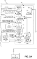
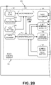
- FIGS. 2A and 2B there is depicted a detailed schematic block diagram of a preferred embodiment of the garage door monitoring and control system 10 located within power head chassis 100.
- the detailed schematic block diagram has been broken into two adjacent portions, namely FIG. 2A depicting, at the right side of the block diagram, the components of the garage door operator (GDO) 180, and FIG. 2B depicting, at the left side of the block diagram, the components of the door control module 150.
- the motor assembly 163 includes (i) a motor 167, which in this embodiment is a DC motor, and (ii) an encoder 166 integrated with motor 167, the encoder 166 in this embodiment being a rotary optical encoder.
- the rotary optical encoder may be of any design effective to generate optical motor signal pulses indicative of the extent and direction of rotation of the output shaft of motor 167, and therefore the extent and direction of travel between limits of the garage door 195, which are subsequently converted to corresponding electrical motor signal pulses
- one preferred embodiment of the rotary optical encoder 166 produces a dual set of electrical output pulses in respective in-phase and quadrature format, and is subsequently described in greater detail in connection with FIGS. 3-7 .
- the encoder 166 generates a dual set of electrical motor signal pulses, the optical pulses initially generated by the encoder having been converted to electrical pulses by a phototransistor (not shown) forming part of the assembly of encoder 166. (As such, both the optical pulses and the electrical pulses are merely differing formats of the motor signal pulses referenced in FIG. 1 .)
- the electrical pulses are subsequently routed via opto connector 187 (which connects the encoder 166 with the GDO board) to and through input buffers 186 and, in turn, as electrical pulses Opto I and Opto-Q, are routed through input buffers 161 of door control module 150 ( FIG. 2B ).
- the dual set of electrical pulses are also routed via opto connector 187 to opto input circuitry 189, and thereafter to the door controller 183 where, among other functions, travel limits for the garage door 195 are maintained.
- the buffered electrical pulses from input buffers 161 are routed to microprocessor 157.
- these electrical pulses are then processed, preferably by programmable-controlled operation, by microprocessor 157 (or other programmable platform) to produce digital door status signals indicative of the status of the garage door 195 (e.g., "open or closed” or “closed or not closed”).
- microprocessor 157 by way of UART serial link, to microprocessor 157 (in direction of upwardly pointed arrow) for initial storage and WiFi conditioning, and thereafter transmission to transceiver 151, where the WiFi door status information is subsequently wirelessly transmitted, as previously described, via the Internet, to the Cloud server 92 and Smartphone 90 ( FIG. 1 ).
- the transceiver 151 of door control module 150 is effective to receive any remotely generated change-of-door-status command, such command then routed to microprocessor 155. After the change-of-door-status command is compared with the door status information previously stored in microprocessor 155, to assure that the change-of-door-status made the subject of the incoming command is not the same as the previously stored status, the incoming change-of-door-status command is then routed by microprocessor 155 (in direction of downwardly pointed arrow) to microprocessor 157.
- the microprocessor 157 then routes the change-of-door-status command, via the door command generator 160 of the door control module 150, and via the input circuitry 184 of the garage door operator 180 ( FIG. 2A ), to the door controller 183 of garage door operator 180.
- the programmed controlled door controller 183 then, via motor controller circuitry 188a and motor connector 188b, instructs the motor 167 to move the garage door in compliance with the change-of-door-status command.
- the microprocessor 157 activates the piezo sounder 154 and light interface circuitry 159 to respectively sound the on board buzzer and flash the worklight 198, to warn anyone near the garage door of the imminent unattended movement of the garage door 195.
- the microprocessor 157 receives the command to move the door 195, an annunciation period begins, during which the piezo sounder 154 and flashing light 198 are activated at the rate and duration in compliance with UL325 requirements. After this annunciation period has expired, the microprocessor 157 then transmits the change-of-door-status command to the door controller 183.
- this embodiment of rotary optical encoder 166 is comprised principally of (i) a wheel 200 affixed to the rotatable shaft 172 of the motor 167 ( FIGS. 3 & 7 ), (ii) dual angularly spaced optical pulse generators 168 and 169 ( FIG. 7 ), with respect to which wheel 200 rotates in conjunction with the rotation of the output shaft of motor 167, generating optical pulses indicative of the extent and direction of rotation of the output shaft, and (iii) a phototransistor converting the optical pulses to electrical pulses.
- wheel 200 has a plurality of upwardly extending, spaced apart, and identically dimensioned paddles 170.
- wheel 200 also has a single, upwardly extending, paddle 171, of a differential (e.g., narrower) size or dimension than that of paddles 170.
- the paddles 170 are arranged in an annular, castellated type, array.
- the two optical pulse generators 168 and 169 each include a light transmitter 176 and a light receiver 175.
- the light transmitters of optical pulse generators 168 and 169 are positioned to direct light rays at the light receivers of optical pulse generators 168 and 169.
- the spaced paddles interrupt the light rays, and generate optical pulses, in accordance with a pattern defined by the pattern of the paddles and the spaces therebetween.
- the identically sized and spaced paddles 170 provide for the generation of evenly spaced optical pulses of the same pulse length, with the paddle 171 providing a light pulse after a shorter interval. While the spacing between paddles may be in accordance with whatever output is desired, in the preferred embodiment shown (and best illustrated in FIG. 5 ), the angular spacing between adjacent paddles 170 is approximately 16.45°, with the spacing between paddle 171 and an adjacent paddle 170 being approximately 28.55° due to the narrower size of the paddle 171.
- the result of having a narrower sized paddle 171 is that one reference pulse is generated for a given number of equally spaced typical pulses 170. In the illustrated embodiment, this would be 15 spaced pulses between paddles 171, and one additional reference pulse for each full rotation of the wheel 200.
- the optical pulse generators 168 and 169 are preferably angularly spaced from one another by 67.50°. This spacing, and the angular spacing between the paddles 170 and 171, are so designed that when the wheel 200 rotates in a first direction, both the pulse generator 168 and the pulse generator 169 simultaneously generate an optical pulse, but when the wheel 200 rotates in an opposite direction, only the pulse generator 168 generates an optical pulse.
- a first pattern of optical pulses are generated by pulse generators 168-169 when the motor shaft is rotating in, say, a clockwise direction
- a second pattern of optical pulses are generated by pulse generators 168-169 when rotating in a counterclockwise direction.
- the processing of the motor signal pulses from the encoder 166 may be in accordance with programmable software executed by microprocessor 157.
- the processing algorithms of such software may be directed to reliably performing the task of determining the location of the close limit and tracking position to determine when the garage door is in sufficient proximity to that close limit to declare the door as being “closed.” All other detected positions of the door may then be declared as "not closed", or "open.”
- the microprocessor 157 under control of the algorithm of the software, may infer, from the motor signal pulse inputs, that it has run in one direction for a predetermined minimum time and then stopped, that the door is away from the other limit. Therefore, if the door runs upwardly and then stops, the determination is that it is not at the close limit. Another algorithm may then be used to confirm that finding.
- microprocessor 157 under control of that algorithm, may record that the minimum and maximum positions that are detected are the working limits.
- the microprocessor 157 interprets the motor signal pulses (i.e., the electrical pulses routed from the input buffers 161 when using a rotary optical encoder) in order to determine the status of the barrier 195. For example, if the first pattern of motor signal pulses are generated (as a consequence of the clockwise rotation of the motor shaft), then the microprocessor 157 interprets the incoming electrical pulses to indicate that the door 195 has moved in the open direction. If the second pattern of motor signal pulses are generated (as a consequence of the counterclockwise rotation of the motor shaft), then the microprocessor 157 interprets the incoming electrical pulses to indicate that the door 195 has moved in the closed direction.
- the motor signal pulses i.e., the electrical pulses routed from the input buffers 161 when using a rotary optical encoder
- the microprocessor 157 may be programmed to use a variety of methods to determine whether the door 195 is closed or not closed, or closed or open. Thus, in accordance with programming of one method, or algorithm, if the pattern of electrical pulses includes at least a predetermined threshold number of pulses, the microprocessor 157 may then interpret the door 195 to be "closed.” Conversely, if the pattern of electrical pulses includes less than the predetermined threshold number of pulses, the microprocessor 157 interprets the barrier to be not closed or open.
- the microprocessor 157 may be programmed to interpret a first pattern of electrical pulses inputted therein, for a predetermined first threshold of time, to mean that the door 195 has moved in the open direction, and is not closed, and to interpret a second pattern of pulses, for a second predetermined threshold of time, to mean that the door 195 is fully closed.
- predetermined threshold periods of time may be user input from the smartphone 90, which then transmits the periods via the Internet, to the microprocessor 157 over the Internet 93/Cloud 92.
- the predetermined threshold periods of time may be factory programmed into microprocessor 157.
- the microprocessor 157 may use the presence or absence of the electrical pulses to verify proper operation. For example, if pulses are not received at the anticipated intervals, then an error has occurred that may mean that the door 195 is stuck. In accordance with a feature of some embodiments of system 10, if errors are detected, the barrier opener system 10 may stop the door 195 or cause it to stop and reverse direction of travel.
- electrical power is provided by power supply 181 not only to the garage door operator (GDO) 180, but also to the door control module 150 after conversion to a suitable voltage level by the DC/DC converter 156.
- the primary power supplied is 16 VAC, with a secondary 13.8 VDC line from a battery.
- the door control module 150 and garage door operator 180 share a common ground. It should be noted that in instances where the door control module 150 is operating on the 13.8 VDC line, the processor 155 may be shut down to conserve power.
- an absolute position sensor may be used to detect the angular position of the rotatable motor shaft.
- An example of a suitable absolute position sensor that can be used as a magnetic pulse generator for pulse encoder 166 is described in U.S. Patent No. 8,113,263, to Reed et al., issued Feb. 14, 2012 , and entitled Barrier Operator With Magnetic Position Sensor, which is incorporated herein by reference in its entirety.
Landscapes
- Physics & Mathematics (AREA)
- General Physics & Mathematics (AREA)
- Engineering & Computer Science (AREA)
- Computer Networks & Wireless Communication (AREA)
- Power-Operated Mechanisms For Wings (AREA)
- Control Of Electric Motors In General (AREA)
Description
- This application claims the benefit of
U.S. Provisional Application Nos. 62/505,711 62/513,943, both titled "REMOTE NETWORK MONITORING AND CONTROL OF A MOVABLE BARRIER" filed May 12, 2017 - The present disclosure relates to the field of remote network monitoring and controlling of the status of a movable barrier, more particularly to the initial determination of the open/close status of a garage door and the subsequent wireless transmission, via the Internet, of such status to an Internet access device such as a user's handheld Smartphone, and even more particularly, in response to the receipt of such garage door status, the transmission, via the Internet, of a change-of-door-status command to move the garage door in compliance with such command.
- Movable barriers, such as upward-acting sectional or single panel garage doors, residential and commercial rollup doors, and slidable and swingable gates, are used to alternatively allow and restrict entry to building structures and property. These barriers are driven between their respective open and closed positions by motors or other motion-imparting mechanisms, which are themselves controlled by barrier moving units, sometimes referred to as "movable barrier operators," and in the specific case of a door, as "door operators," and in the even more specific case of a garage door, as "garage door operators." Garage door operators are effective to cause the DC or AC motor, and accompanying motor drive assembly, to move the associated garage door, typically between its open and closed positions.
- Each garage door operator includes a door controller (typically, a microprocessor, microcontroller, or other programmable platform) for processing incoming door commands and generating output control signals to the motor which, in combination with its associated drive assembly, moves the garage door in accordance with the incoming door commands. The incoming door commands, in the past, have been in the form of wired or wireless signals transmitted from interior or exterior wall consoles, or from proximately located hand held or vehicle mounted RF transmitters.
- However, with the near ubiquity of the Internet and the proliferation of electronic devices and equipment designed to access the Internet, such as personal computers, cellphones, and Smartphones, systems are currently being designed and implemented in the trade that enable non-proximate, or remote, monitoring and control, via the Internet, of door status. For example, if a homeowner is not in proximity to its residence, and wants to determine whether the garage door the homeowner had intended to close, did in fact close, or whether the garage door it intended to leave open for a workman to enter, had in fact been left open, using one of these systems, the homeowner can, through access to the Internet, remotely monitor the status of the garage door (e.g., whether it is open or closed). Moreover, if the garage door is not in the desired position, these systems are designed to also enable the homeowner to transmit change-of-door status commands over the Internet to move the garage door to the desired position, all without having to be physically proximate the garage to do so.
- These aforestated systems typically use means capable of determining the status of the garage door that is then remotely transmitted to the homeowner. For example, some systems use door status monitoring apparatus affixed to, or proximate, the garage door to directly monitor the garage door status. While this approach is generally acceptable for many applications, the requirement to have separate apparatus affixed to, or proximate, the garage door may, for various reasons, not be the most desired approach. Other systems have indirectly determined door status from the door controller of the garage door operator (i.e., from the microprocessor, microcontroller or other programmable platform of the garage door opener). However, these systems have not been entirely acceptable for all conditions of service.
- It is therefore among the objectives of the embodiments of the remote door status monitoring and control system and method disclosed herein to present a new and improved version of such system and method, in particular a system and method that is reliable, takes advantage of Internet signal transmission, and is convenient to install and use.
- In a first aspect of the present invention a remote garage door status monitoring and control system is presented according to claim 1.
- In accordance with the aforementioned and other objectives, disclosed herein are alternative embodiments of a remote movable barrier status monitoring and control system and method that enables the initial accurate determination of the status of a movable barrier (e.g., the garage door), such status typically being whether the door is open or closed, or closed or not closed, followed by the effective transmission of that door status, via the Internet, to the user of an Internet access device, like a Smartphone, so as to enable the user to remotely monitor the movable barrier status. Among the advantages of the herein described system and method is preferably that the barrier status determination (i.e., the monitoring operation) is carried out (i) without the requirement of barrier monitoring apparatus physically attached to, or proximate, the monitored movable barrier (e.g., the garage door), and (ii) without having to obtain garage door status information from the garage door operator, nor particularly from the programmable platform controller of the garage door operator. Instead, the status determination operation of the present invention is derived from the operation of the motor that drives the garage door.
- Accordingly, the disclosed system and method incorporating the principles of the present invention (i) initially produces motor signal pulses indicative of the extent and direction of rotation of the rotatable shaft of the motor associated with the monitored movable barrier, and therefore the extent and direction of travel of the movable barrier itself; and (ii) thereafter, pursuant to the programmable-controlled operation by a microprocessor, microcontroller, or the like in the door control module, these motor signal pulses are converted to digital signals indicative of the open/closed or other desired status of the movable barrier. Such digital door status signals are thereafter wirelessly transmitted by the door control module, via the Internet, to the remotely located Smartphone, or other suitable Internet access device.
- Thereafter, in accordance with the control aspect of the herein described remote status monitoring and control system, should it be determined that the status of the movable barrier (i.e., the garage door) should be changed (for example, from open to closed), the user of the Smartphone transmits a change-of-door status command back to the door control module, via the Internet, the door control module thereafter transmitting such command to the garage door operator, specifically the programmable platform controller, that then responsively directs the motor to move the garage door to the status (i.e., position) instructed by the change-of-door-status command. Thus, the garage door operator controller plays no role in determining the status of the garage door, its sole door-related function in the overall system of this invention being to transmit remotely (or locally) transmitted door movement commands to the motor.
- According to the invention, motor signal pulses are initially generated by an encoder responsive to the rotational movement of the rotatable output shaft of the motor driving the garage door, the encoder producing motor signal pulses preferably corresponding to the extent and direction of such rotational (angular) movement, and therefore corresponding to the extent and direction of movement of the door.
- In accordance with one preferred embodiment of an encoder, the design and operation of which are subsequently described in greater detail, the generation of the motor signal pulses is preferably provided by a rotary optical encoder that produces optical pulses corresponding to the extent and direction of rotation of the motor shaft, and therefore the extent and direction of door movement. This optical encoder preferably includes a wheel attached to the rotatable output shaft of the motor and preferably has spaced paddles projecting therefrom. The spaces or "gaps" between the paddles permit the selective passage of light therethrough, preferably the light emanating from a light "transmitter" directing its light rays toward a light sensor or "receiver," dual optical pulse generators radially offset from one another a prescribed distance include respective sets of a light transmitter and light receiver, with the gapped wheel, rotating with the rotation of the motor shaft, disposed between a light transmitter and light receiver. The resulting pattern of light impingement on the light receivers, coupled with the angular displacement of the optical pulse generators, result in the generation of optical pulses indicative of the extent and direction of rotation of the motor shaft, and therefore preferably the extent and direction of movement of the garage door within its travel limits. A phototransistor, preferably forming part of the encoder, then preferably converts these optical motor signal pulses to electrical motor signal pulses.
- In accordance with a unique feature of the disclosed system, buffered ones of the electrical motor signal pulses are then routed to a microprocessor (or other programmable platform) of the door control module, where they are preferably programmably processed/converted to digital signals indicative of the alternate status of the garage door, typically the open or closed status thereof.
- Additional features, aspects, and objectives of the disclosed embodiments of the remote movable barrier status monitoring and control system and method will become readily apparent to those skilled in the art from the hereinafter detailed description, read in conjunction with the following drawings.
- In a further aspect of the invention a method for monitoring and controlling remotely the status of a garage door or the like is presented according to claim 11.
- The steps of the inventive methods can, at least partly, be written in a program code for a computer program that can be, at least partly, performed by a computer or a microprocessor.
- Preferred embodiments of the invention are defined in the dependent claims.
- These and other aspects of the invention will be apparent from and elucidated with reference to the embodiment(s) described hereinafter. In the following drawings
- FIG. 1
- is a block diagram of an embodiment of the interconnection of the principal components of a remote movable barrier status monitoring and control system in accordance with the principles of the present invention.
- FIGS. 2A and 2B
- each respectively show a portion, and together show the entirety, of a more detailed schematic block diagram of the remote movable barrier status monitoring and control system of
FIG. 1 . - FIG. 3
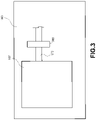
- is a schematic diagram of a motor pulse encoder responsive to the extent and direction of travel of a rotatable output shaft of a garage door motor adapted to move the garage door.
- FIG. 4
- is a perspective view of the gapped wheel portion of a preferred embodiment of a rotary optical encoder providing the function of the motor pulse encoder of
FIG. 3 . - FIG. 5
- is a front view of the wheel of
FIG. 4 . - FIG. 6
- is a top view of the cover of the wheel of
FIG. 4 . - FIG. 7
- is a perspective view of the mounting and interaction of the gapped wheel illustrated in
FIGS. 4-6 with respective optical pulse generators of the rotary optical encoder. - Embodiments of the remote movable barrier status monitoring and control system in accordance with the principles of the present invention, as defined solely by the appended claims, will be described below. These described embodiments are only non-limiting examples of implementations of the invention as defined solely by the attached claims. Additionally, in an effort to provide a focus of the description of important features of the disclosed embodiments emphasizing the principles of the present invention, some details that may be incorporated, or may prefer to be incorporated, in a commercial implementation of the herein described system, but are not necessary for an understanding of the invention by one skilled in the art, have been omitted in order to highlight the important features relevant to an understanding of the invention. Also, the accompanying drawing figures are not necessarily to scale and certain elements may be shown in generalized, schematic or block diagram format in the interest of clarity and conciseness.
- With initial reference now to
FIG. 1 , there is depicted a block diagram of the overall process, and interconnection of the principal components of a new and improved remote garage door status monitoring andcontrol system 10, incorporating the principles of the present invention. Accordingly, thesystem 10 remotely determines and monitors the status (e.g., closed/not closed or open/closed) of thegarage door 195 as well as remotely effecting change of the status of such door. Specifically, thesystem 10 includes apower head chassis 100 that enclosesmotor assembly 163,garage door operator 180, anddoor control module 150. As subsequently described in greater detail with reference toFIGS. 3-7 , themotor assembly 163 includes (i) amotor 167 adapted to move the garage door in the conventional manner known by one of ordinary skill in the industry, and (ii) anencoder 166 integrated with themotor 167 for generating motor signal pulses responsive to the operation of themotor 167, and specifically responsive to, and indicative of, the extent and direction of rotation of the rotatable output shaft ofmotor 167, and therefore indicative of the extent and direction of travel of thegarage door 195 between travel limits. - The
motor 167 is operatively coupled to aconventional drive assembly 196, themotor 167 and drive assembly 196 effective to impart movement to thedoor 195 in accordance with door commands remotely and/or proximately transmitted togarage door operator 180 and thereafter tomotor 167. Thedrive assembly 196 may be any of the standard and conventional drive assemblies available on the market that are suitable to move thegarage door 195 in response tomotor 167. - In accordance with the overall operation of the garage door status monitoring and
control system 10, the motor signal pulses, generated to correspond to the operation ofmotor 167, and specifically indicative of the extent and direction of motor shaft rotation, and therefore the extent and direction (up or down) ofgarage door 195, are conductively transmitted by wire to thedoor control module 150, the design and operation of which are subsequently described with reference toFIGS. 2A and2B . These motor signal pulses may initially be in the form, for example, of optical pulses, and then converted to electrical motor signal pulses inputted todoor control module 150. - The
door control module 150 is effective to process and convert the incoming motor signal pulses to digital door status signals indicative of the garage door status, for example "open/closed" or "closed/not closed" status, of thegarage door 195. This door status information is then wirelessly transmitted by thedoor control module 150, via aWiFi home router 94, to (and for storage in)cloud server 92 of theInternet 93, where such status information is subsequently pushed to aSmartphone 90, or any other suitable Internet access device, such as a desktop or laptop computer, personal data assistant (PDA), mobile phone, tablet, or the like, for user review of the then current garage door status. It is emphasized that nowhere insystem 10 is door status ever requested, the door status information always being "pushed" to the next component or stage. - With continuing reference to
FIG. 1 , thesystem 10 is also effective to wirelessly transmit a change-of-door-status command fromSmartphone 90, via the Internet andcloud server 92, andhome router 94, back to thedoor control module 150. Change-of-door-status commands may also be initiated from theCloud server 92 in appropriate situations, such as a pre-programmed time-to-close, or other pre-programmed activities. - Upon receipt of the remotely generated change-of-door-status command,
door control module 150 is effective to transmit the change-of-door-status (and corresponding light) commands to thegarage door operator 180, specifically to the door controller 183 (FIG. 2A ) ofgarage door operator 180, along with a command to flash thework light 198 in accordance with the sequence subsequently described. In accordance with conventional procedure, user-generated door toggle open/close commands may also be transmitted to thedoor operator 180 fromwall console 165, which, as conventionally known, turns on theworklight 198 simultaneously with the operation of themotor 167. One or more handheld or vehicle-mountedRF transmitters 91 proximate to thegarage door 195 may also transmit door commands to thedoor operator 180 in similar manner aswall console 165. - Referring now to
FIGS. 2A and2B , there is depicted a detailed schematic block diagram of a preferred embodiment of the garage door monitoring andcontrol system 10 located withinpower head chassis 100. For clarity of presentation, the detailed schematic block diagram has been broken into two adjacent portions, namelyFIG. 2A depicting, at the right side of the block diagram, the components of the garage door operator (GDO) 180, andFIG. 2B depicting, at the left side of the block diagram, the components of thedoor control module 150. - Referring initially to
FIG. 2A , themotor assembly 163 includes (i) amotor 167, which in this embodiment is a DC motor, and (ii) anencoder 166 integrated withmotor 167, theencoder 166 in this embodiment being a rotary optical encoder. While the rotary optical encoder may be of any design effective to generate optical motor signal pulses indicative of the extent and direction of rotation of the output shaft ofmotor 167, and therefore the extent and direction of travel between limits of thegarage door 195, which are subsequently converted to corresponding electrical motor signal pulses, one preferred embodiment of the rotaryoptical encoder 166 produces a dual set of electrical output pulses in respective in-phase and quadrature format, and is subsequently described in greater detail in connection withFIGS. 3-7 . - As illustrated in
FIG. 2A , theencoder 166 generates a dual set of electrical motor signal pulses, the optical pulses initially generated by the encoder having been converted to electrical pulses by a phototransistor (not shown) forming part of the assembly ofencoder 166. (As such, both the optical pulses and the electrical pulses are merely differing formats of the motor signal pulses referenced inFIG. 1 .) - The electrical pulses are subsequently routed via opto connector 187 (which connects the
encoder 166 with the GDO board) to and throughinput buffers 186 and, in turn, as electrical pulses Opto I and Opto-Q, are routed throughinput buffers 161 of door control module 150 (FIG. 2B ). The dual set of electrical pulses are also routed viaopto connector 187 toopto input circuitry 189, and thereafter to thedoor controller 183 where, among other functions, travel limits for thegarage door 195 are maintained. - With continuing reference to
FIG. 2B , the buffered electrical pulses frominput buffers 161 are routed tomicroprocessor 157. In accordance with the technique subsequently described, these electrical pulses are then processed, preferably by programmable-controlled operation, by microprocessor 157 (or other programmable platform) to produce digital door status signals indicative of the status of the garage door 195 (e.g., "open or closed" or "closed or not closed"). The so-generated digital door status signals are then transmitted frommicroprocessor 157, by way of UART serial link, to microprocessor 157 (in direction of upwardly pointed arrow) for initial storage and WiFi conditioning, and thereafter transmission totransceiver 151, where the WiFi door status information is subsequently wirelessly transmitted, as previously described, via the Internet, to theCloud server 92 and Smartphone 90 (FIG. 1 ). - The
transceiver 151 ofdoor control module 150 is effective to receive any remotely generated change-of-door-status command, such command then routed tomicroprocessor 155. After the change-of-door-status command is compared with the door status information previously stored inmicroprocessor 155, to assure that the change-of-door-status made the subject of the incoming command is not the same as the previously stored status, the incoming change-of-door-status command is then routed by microprocessor 155 (in direction of downwardly pointed arrow) tomicroprocessor 157. - The
microprocessor 157 then routes the change-of-door-status command, via thedoor command generator 160 of thedoor control module 150, and via theinput circuitry 184 of the garage door operator 180 (FIG. 2A ), to thedoor controller 183 ofgarage door operator 180. The programmed controlleddoor controller 183 then, viamotor controller circuitry 188a andmotor connector 188b, instructs themotor 167 to move the garage door in compliance with the change-of-door-status command. - However, prior to the
microprocessor 157 routing the change-of-door-status command to thedoor controller 183, themicroprocessor 157 activates thepiezo sounder 154 andlight interface circuitry 159 to respectively sound the on board buzzer and flash theworklight 198, to warn anyone near the garage door of the imminent unattended movement of thegarage door 195. Thus, when themicroprocessor 157 receives the command to move thedoor 195, an annunciation period begins, during which thepiezo sounder 154 and flashing light 198 are activated at the rate and duration in compliance with UL325 requirements. After this annunciation period has expired, themicroprocessor 157 then transmits the change-of-door-status command to thedoor controller 183. - In accordance with the preferred embodiment of the rotary
optical encoder 166, reference now is toFIGS. 3-7 of the drawings. Accordingly, this embodiment of rotaryoptical encoder 166 is comprised principally of (i) awheel 200 affixed to therotatable shaft 172 of the motor 167 (FIGS. 3 &7 ), (ii) dual angularly spacedoptical pulse generators 168 and 169 (FIG. 7 ), with respect to whichwheel 200 rotates in conjunction with the rotation of the output shaft ofmotor 167, generating optical pulses indicative of the extent and direction of rotation of the output shaft, and (iii) a phototransistor converting the optical pulses to electrical pulses. - As best illustrated in
FIGS. 4 &7 ,wheel 200 has a plurality of upwardly extending, spaced apart, and identically dimensioned paddles 170. Notably,wheel 200 also has a single, upwardly extending,paddle 171, of a differential (e.g., narrower) size or dimension than that ofpaddles 170. As shown inFIG. 4 , thepaddles 170 are arranged in an annular, castellated type, array. The twooptical pulse generators light transmitter 176 and alight receiver 175. The light transmitters ofoptical pulse generators optical pulse generators - Thus, the identically sized and spaced
paddles 170 provide for the generation of evenly spaced optical pulses of the same pulse length, with thepaddle 171 providing a light pulse after a shorter interval. While the spacing between paddles may be in accordance with whatever output is desired, in the preferred embodiment shown (and best illustrated inFIG. 5 ), the angular spacing betweenadjacent paddles 170 is approximately 16.45°, with the spacing betweenpaddle 171 and anadjacent paddle 170 being approximately 28.55° due to the narrower size of thepaddle 171. The result of having a narrowersized paddle 171 is that one reference pulse is generated for a given number of equally spacedtypical pulses 170. In the illustrated embodiment, this would be 15 spaced pulses betweenpaddles 171, and one additional reference pulse for each full rotation of thewheel 200. - As best illustrated in
FIG. 6 , theoptical pulse generators paddles wheel 200 rotates in a first direction, both thepulse generator 168 and thepulse generator 169 simultaneously generate an optical pulse, but when thewheel 200 rotates in an opposite direction, only thepulse generator 168 generates an optical pulse. Thus, a first pattern of optical pulses are generated by pulse generators 168-169 when the motor shaft is rotating in, say, a clockwise direction, while a second pattern of optical pulses are generated by pulse generators 168-169 when rotating in a counterclockwise direction. - The processing of the motor signal pulses from the
encoder 166 may be in accordance with programmable software executed bymicroprocessor 157. For example, the processing algorithms of such software may be directed to reliably performing the task of determining the location of the close limit and tracking position to determine when the garage door is in sufficient proximity to that close limit to declare the door as being "closed." All other detected positions of the door may then be declared as "not closed", or "open." Thus, themicroprocessor 157, under control of the algorithm of the software, may infer, from the motor signal pulse inputs, that it has run in one direction for a predetermined minimum time and then stopped, that the door is away from the other limit. Therefore, if the door runs upwardly and then stops, the determination is that it is not at the close limit. Another algorithm may then be used to confirm that finding. Thus,microprocessor 157, under control of that algorithm, may record that the minimum and maximum positions that are detected are the working limits. - Thus, in accordance with the monitoring aspect of the
system 10 that determines the existing door status, themicroprocessor 157 interprets the motor signal pulses (i.e., the electrical pulses routed from the input buffers 161 when using a rotary optical encoder) in order to determine the status of thebarrier 195. For example, if the first pattern of motor signal pulses are generated (as a consequence of the clockwise rotation of the motor shaft), then themicroprocessor 157 interprets the incoming electrical pulses to indicate that thedoor 195 has moved in the open direction. If the second pattern of motor signal pulses are generated (as a consequence of the counterclockwise rotation of the motor shaft), then themicroprocessor 157 interprets the incoming electrical pulses to indicate that thedoor 195 has moved in the closed direction. - In summary, the
microprocessor 157 may be programmed to use a variety of methods to determine whether thedoor 195 is closed or not closed, or closed or open. Thus, in accordance with programming of one method, or algorithm, if the pattern of electrical pulses includes at least a predetermined threshold number of pulses, themicroprocessor 157 may then interpret thedoor 195 to be "closed." Conversely, if the pattern of electrical pulses includes less than the predetermined threshold number of pulses, themicroprocessor 157 interprets the barrier to be not closed or open. - As another example, the
microprocessor 157 may be programmed to interpret a first pattern of electrical pulses inputted therein, for a predetermined first threshold of time, to mean that thedoor 195 has moved in the open direction, and is not closed, and to interpret a second pattern of pulses, for a second predetermined threshold of time, to mean that thedoor 195 is fully closed. - These predetermined threshold periods of time may be user input from the
smartphone 90, which then transmits the periods via the Internet, to themicroprocessor 157 over theInternet 93/Cloud 92. Alternatively, the predetermined threshold periods of time may be factory programmed intomicroprocessor 157. - The
microprocessor 157 may use the presence or absence of the electrical pulses to verify proper operation. For example, if pulses are not received at the anticipated intervals, then an error has occurred that may mean that thedoor 195 is stuck. In accordance with a feature of some embodiments ofsystem 10, if errors are detected, thebarrier opener system 10 may stop thedoor 195 or cause it to stop and reverse direction of travel. - In accordance with another feature of the
system 10, electrical power is provided bypower supply 181 not only to the garage door operator (GDO) 180, but also to thedoor control module 150 after conversion to a suitable voltage level by the DC/DC converter 156. The primary power supplied is 16 VAC, with a secondary 13.8 VDC line from a battery. Thedoor control module 150 andgarage door operator 180 share a common ground. It should be noted that in instances where thedoor control module 150 is operating on the 13.8 VDC line, theprocessor 155 may be shut down to conserve power. - Various type apparatus may be used for the
pulse encoder 166. For example, an absolute position sensor may be used to detect the angular position of the rotatable motor shaft. An example of a suitable absolute position sensor that can be used as a magnetic pulse generator forpulse encoder 166 is described inU.S. Patent No. 8,113,263, to Reed et al., issued Feb. 14, 2012 , and entitled Barrier Operator With Magnetic Position Sensor, which is incorporated herein by reference in its entirety. - Various modifications may be made to the disclosed embodiments without departing from the principles of the present invention. For example, while the specific examples set forth-above describe transmitting the door status information, or transmitting the change-of-door-status command, via a separate Wi-
Fi home router 94, it should be understood that this is a non-limiting example, and therouter 94 may alternatively be part of theInternet 93. - Moreover, those skilled in the art, having benefit of this disclosure, will appreciate that other embodiments can be envisioned that do not depart from the scope of the invention as defined solely by the attached claims.
- In the claims, the word "comprising" does not exclude other elements or steps, and the indefinite article "a" or "an" does not exclude a plurality. A single element or other unit may fulfill the functions of several items recited in the claims.
Claims (10)
- Remote garage door status monitoring and control system (10) comprising:a motor (167) operable to move a garage door (195) to alternative garage door status positions,a garage door operator (180) configured to receive door commands remotely and/or proximately transmitted to the garage door operator and having a door controller (183) operable to generate a door command to move the garage door to one of the alternative garage door status positions in compliance with said door command,an encoder (166) integrated with the motor and operable to generate motor signal pulses indicative of the extent and direction of movement of the garage door,a door control module (150) having a programmable controlled microprocessor (157) for converting said motor signal pulses to digital door status signals indicative of one of the alternative garage door status positions,a power head chassis (100) that encloses the motor assembly (163), the garage door operator (180), and the door control module (150); anda wireless transceiver (151) for transmitting, via the Internet, to a remotely located Internet access device (90), door status position information corresponding to said digital door status signals, wherein the wireless transceiver (151) is operably coupled to the programmable controlled microprocessor (157), and not operably coupled to the door controller (183),wherein when change-of-door-status commands are user-generated by said remotely located Internet access device, said change-of-door-status commands are wirelessly transmitted back to said transceiver, further routed to said microprocessor, and said microprocessor is adapted to direct said change-of-door-status commands to the door controller, wherein the programmed controlled door controller (183) instructs the motor (167) to move the garage door in compliance with the change-of-door-status command.
- Remote garage door status monitoring and control system of claim 1 in which the alternative garage door status positions are open and closed.
- Remote garage door status monitoring and control system of claim 1 in which the alternative garage door status positions are closed and not closed.
- Remote garage door status monitoring and control system of claim 1, in which the motor has a rotatable output shaft (172), and the encoder is a rotary optical encoder generating optical pulses indicative of the extent and direction of rotational movement of the rotatable output shaft.
- Remote garage door status monitoring and control system of claim 1, wherein the optical pulses are converted to electrical pulses inputted to said programmable controlled microprocessor (157).
- Remote garage door status monitoring and control system of claim 5 in which the optical encoder (166) comprises (i) a wheel (200) having spaced paddles (170) projecting therefrom with spaces defined between the paddles, the wheel affixed to the rotatable output shaft (172) of the motor (167) for rotation therewith, and (ii) a pair of optical pulse generators (168, 169), said optical pulse generators being angularly disposed with respect to one another, and each having a light transmitter and a light receiver, rays of light emanating from said light transmitter toward said light receiver, the rotating wheel interrupting the light received by the light receivers in a pattern that, coupled with the angular displacement of the optical pulse generators, result in the generation of said optical pulses indicative of the extent and direction of rotation of the motor shaft, and thus the extent and direction of movement of the garage door.
- Remote garage door status monitoring and control system of claim 5, in which said alternative garage door status positions are closed and not closed, respectively.
- Remote garage door status monitoring and control system of claim 1, in which the encoder (166) is a rotary optical encoder comprising (i) a wheel (200) having circumferentially defined gaps through which light can pass, said wheel affixed to a rotatable output shaft (172) of the motor (167) to rotate therewith, and (ii) a pair of optical pulse generators (168, 169), angularly disposed with respect to one another, each having a light transmitter and a light receiver upon which light from the light transmitter is directed, the rotation of the wheel resulting in the rotation of the said gaps between the light transmitter and the light receiver in a pattern that controls, at least in part, the generation of said motor signal pulses.
- Remote garage door status monitoring and control system of claim 8, wherein the pair of optical pulse generators (168, 169) simultaneously generate optical pulses when the wheel (200) rotates in a first direction and do not simultaneously generate optical pulses when the wheel rotates in an opposite direction.
- Method for determining and controlling the status of a garage door with a system according to claims 1-9, comprising the following steps:Generating door commands by a garage door controller of a garage door opener and providing commands to a motor of the garage door to move the garage door between alternative garage door status positions in response to the door commands,Generating by an encoder integrated with the motor motor signal pulses being indicative of the extent and direction of movement of the garage door,Receiving the motor signal pulses from the encoder by a microprocessor and converting the motor signal pulses to digital door status signals indicative of which of the alternative garage door status positions the garage door has been moved to,Generating door status information from and corresponding to the digital door status signals,Transmitting wirelessly, via the Internet, to a remotely located Internet access device by a wireless door status condition transceiver garage door status position information corresponding to said digital door status signals,User-generating change-of-door-status command by said remotely located Internet access device, andTransmitting change-of-door-status command wirelessly back to said transceiver,Routing change-of-door-status command further to said microprocessor, Directing said change-of-door-status commands to the door controller,Instructing the motor (167) to move the garage door in compliance with the change-of-door-status command.
Applications Claiming Priority (3)
| Application Number | Priority Date | Filing Date | Title |
|---|---|---|---|
| US201762505711P | 2017-05-12 | 2017-05-12 | |
| US201762513943P | 2017-06-01 | 2017-06-01 | |
| US15/800,510 US10540889B2 (en) | 2017-05-12 | 2017-11-01 | Remote monitoring and control of movable barrier status |
Publications (2)
| Publication Number | Publication Date |
|---|---|
| EP3401486A1 EP3401486A1 (en) | 2018-11-14 |
| EP3401486B1 true EP3401486B1 (en) | 2022-10-12 |
Family
ID=62152474
Family Applications (1)
| Application Number | Title | Priority Date | Filing Date |
|---|---|---|---|
| EP18171888.3A Active EP3401486B1 (en) | 2017-05-12 | 2018-05-11 | Remote network monitoring and control of a movable barrier status |
Country Status (4)
| Country | Link |
|---|---|
| US (1) | US10540889B2 (en) |
| EP (1) | EP3401486B1 (en) |
| CA (1) | CA3004557C (en) |
| ES (1) | ES2929656T3 (en) |
Families Citing this family (8)
| Publication number | Priority date | Publication date | Assignee | Title |
|---|---|---|---|---|
| US11795753B1 (en) * | 2018-04-25 | 2023-10-24 | Gmi Holdings, Inc. | Remote monitoring and control of garage door opener incorporating jackshaft door operator drive assembly |
| US11156008B2 (en) * | 2018-11-26 | 2021-10-26 | The Boeing Company | Collapsible guardrail |
| US11746584B2 (en) * | 2019-04-24 | 2023-09-05 | Gmi Holdings, Inc. | Remote monitoring and control of moveable barrier in jackshaft door operator system |
| US11308019B2 (en) | 2019-05-30 | 2022-04-19 | D. H. Pace Company, Inc. | Systems and methods for door and dock equipment servicing |
| CN113949993A (en) * | 2020-06-30 | 2022-01-18 | 荣耀终端有限公司 | Method for starting motion mode and electronic equipment |
| CN111935225A (en) * | 2020-07-08 | 2020-11-13 | 扬州哈工科创机器人研究院有限公司 | Method and system for measuring and controlling stepping motor by mobile terminal |
| US11980962B2 (en) * | 2020-11-19 | 2024-05-14 | Preston Busby | Energy weld welding calculator and monitoring system and device |
| US12574441B1 (en) | 2025-02-11 | 2026-03-10 | Gmi Holdings, Inc. | Movable barrier anomaly detection and data backfilling |
Citations (2)
| Publication number | Priority date | Publication date | Assignee | Title |
|---|---|---|---|---|
| US20020183008A1 (en) * | 2001-05-29 | 2002-12-05 | Menard Raymond J. | Power door control and sensor module for a wireless system |
| US20140320263A1 (en) * | 2013-04-26 | 2014-10-30 | GM Global Technology Operations LLC | Methods, program products, and systems relating to vehicular garage door control systems |
Family Cites Families (17)
| Publication number | Priority date | Publication date | Assignee | Title |
|---|---|---|---|---|
| US3262105A (en) | 1961-01-03 | 1966-07-19 | Hughes Aircraft Co | Condition responsive electrical system |
| US4338553A (en) | 1979-12-04 | 1982-07-06 | Scott Jr Waller M | Control system for a motor actuated door operating mechanism |
| US5039925A (en) | 1990-09-24 | 1991-08-13 | Itt Corporation | Position encoder for sliding door power drive system |
| US6172475B1 (en) | 1998-09-28 | 2001-01-09 | The Chamberlain Group, Inc. | Movable barrier operator |
| EP1161795B1 (en) | 1999-02-17 | 2004-04-28 | The Chamberlain Group, Inc. | Method and apparatus determining position of a movable barrier |
| US6495983B1 (en) * | 2001-06-28 | 2002-12-17 | Michael A. Stern | Integrated closed-loop programmable motor assembly |
| US6998977B2 (en) | 2003-04-28 | 2006-02-14 | The Chamberlain Group, Inc. | Method and apparatus for monitoring a movable barrier over a network |
| US7071813B2 (en) | 2003-05-29 | 2006-07-04 | The Chamberlain Group, Inc. | Status signal method and apparatus for movable barrier operator and corresponding wireless remote control |
| US7224275B2 (en) | 2003-05-29 | 2007-05-29 | The Chamberlain Group, Inc. | Movable barrier operators status condition transception apparatus and method |
| US7956718B2 (en) | 2004-12-16 | 2011-06-07 | Overhead Door Corporation | Remote control and monitoring of barrier operators with radio frequency transceivers |
| US7208897B2 (en) * | 2005-03-04 | 2007-04-24 | Linear Corporation | Motion control system for barrier drive |
| US8113263B2 (en) | 2005-06-30 | 2012-02-14 | Overhead Door Corporation | Barrier operator with magnetic position sensor |
| US20100127882A1 (en) * | 2008-11-25 | 2010-05-27 | Toyota Motor Engineering & Manufacturing North America, Inc. | Garage Door Closing Confirmation Systems and Methods |
| US8587404B2 (en) * | 2009-03-24 | 2013-11-19 | The Chamberlain Group, Inc. | Movable barrier operator and transmitter with imminent barrier moving notification |
| US9208629B2 (en) * | 2012-10-30 | 2015-12-08 | Continental Automotive Systems, Inc. | Garage door open alert |
| DE102013107015A1 (en) | 2013-01-14 | 2014-07-17 | Hörmann KG Antriebstechnik | Building or enclosure completion remote control and uses thereof |
| US20160281411A1 (en) * | 2015-03-26 | 2016-09-29 | Leo John Calagaz, JR. | Garage Door Controller |
-
2017
- 2017-11-01 US US15/800,510 patent/US10540889B2/en active Active
-
2018
- 2018-05-10 CA CA3004557A patent/CA3004557C/en active Active
- 2018-05-11 ES ES18171888T patent/ES2929656T3/en active Active
- 2018-05-11 EP EP18171888.3A patent/EP3401486B1/en active Active
Patent Citations (2)
| Publication number | Priority date | Publication date | Assignee | Title |
|---|---|---|---|---|
| US20020183008A1 (en) * | 2001-05-29 | 2002-12-05 | Menard Raymond J. | Power door control and sensor module for a wireless system |
| US20140320263A1 (en) * | 2013-04-26 | 2014-10-30 | GM Global Technology Operations LLC | Methods, program products, and systems relating to vehicular garage door control systems |
Also Published As
| Publication number | Publication date |
|---|---|
| EP3401486A1 (en) | 2018-11-14 |
| US10540889B2 (en) | 2020-01-21 |
| ES2929656T3 (en) | 2022-11-30 |
| CA3004557A1 (en) | 2018-11-12 |
| CA3004557C (en) | 2020-04-07 |
| US20180330605A1 (en) | 2018-11-15 |
Similar Documents
| Publication | Publication Date | Title |
|---|---|---|
| CA3004557C (en) | Remote monitoring and control of movable barrier status | |
| US10614647B2 (en) | Remote transmission of barrier status and change of status over a network | |
| AU2023203904B2 (en) | Barrier operator feature enhancement | |
| US20220351611A1 (en) | Remote monitoring and control of movable barrier status | |
| US11746584B2 (en) | Remote monitoring and control of moveable barrier in jackshaft door operator system | |
| US8643465B2 (en) | Network ID activated transmitter | |
| US8279040B2 (en) | System and method for control of multiple barrier operators | |
| US20230340831A1 (en) | Remote monitoring and control of movable barrier status in system incorporating residential jackshaft door operator | |
| US20040160205A1 (en) | Automatic gate operator | |
| KR20160113440A (en) | Remote control system using home robot equipped with home appliances control device and method of thereof | |
| WO2018183698A1 (en) | Command and confirm electronic shutter systems | |
| CA3079476A1 (en) | Remote monitoring and control of moveable barrier in jackshaft door operator system | |
| US7327249B1 (en) | Barrier operator system having multiple frequency receivers | |
| EP2612977A2 (en) | A multi-barrier operator system | |
| US20050099151A1 (en) | Positioning/adjusting device for a shielding member | |
| US10954708B2 (en) | Movable barrier opener with brushless DC motor | |
| US20160177608A1 (en) | Barrier Identification for Automated Configuration of Barrier Operator | |
| CA3065372A1 (en) | Remote monitoring and control of movable barrier status | |
| EP1869646B1 (en) | Frequency matching and optimization system for an rf receiver | |
| JP7554639B2 (en) | Automatic doors, electronic devices, automatic door operation methods, automatic door operation programs | |
| JPH0683401A (en) | Driven object control device | |
| NZ626250B2 (en) | A Multi-Barrier Operator System | |
| HK1185644A (en) | Operating method for an electromechanical actuator controlling a movable closure or blind element in a building | |
| HK1185644B (en) | Operating method for an electromechanical actuator controlling a movable closure or blind element in a building |
Legal Events
| Date | Code | Title | Description |
|---|---|---|---|
| PUAI | Public reference made under article 153(3) epc to a published international application that has entered the european phase |
Free format text: ORIGINAL CODE: 0009012 |
|
| STAA | Information on the status of an ep patent application or granted ep patent |
Free format text: STATUS: THE APPLICATION HAS BEEN PUBLISHED |
|
| AK | Designated contracting states |
Kind code of ref document: A1 Designated state(s): AL AT BE BG CH CY CZ DE DK EE ES FI FR GB GR HR HU IE IS IT LI LT LU LV MC MK MT NL NO PL PT RO RS SE SI SK SM TR |
|
| AX | Request for extension of the european patent |
Extension state: BA ME |
|
| STAA | Information on the status of an ep patent application or granted ep patent |
Free format text: STATUS: REQUEST FOR EXAMINATION WAS MADE |
|
| 17P | Request for examination filed |
Effective date: 20190514 |
|
| RBV | Designated contracting states (corrected) |
Designated state(s): AL AT BE BG CH CY CZ DE DK EE ES FI FR GB GR HR HU IE IS IT LI LT LU LV MC MK MT NL NO PL PT RO RS SE SI SK SM TR |
|
| STAA | Information on the status of an ep patent application or granted ep patent |
Free format text: STATUS: EXAMINATION IS IN PROGRESS |
|
| 17Q | First examination report despatched |
Effective date: 20200326 |
|
| GRAP | Despatch of communication of intention to grant a patent |
Free format text: ORIGINAL CODE: EPIDOSNIGR1 |
|
| STAA | Information on the status of an ep patent application or granted ep patent |
Free format text: STATUS: GRANT OF PATENT IS INTENDED |
|
| INTG | Intention to grant announced |
Effective date: 20220509 |
|
| RIN1 | Information on inventor provided before grant (corrected) |
Inventor name: DRAGOMIER, MICHAEL Inventor name: MATIAS, GREGORY D. Inventor name: RAUSCHER, BRENT ALAN Inventor name: BUESCHER, BRENT Inventor name: KRUPKE, LEROY G. Inventor name: IKELER, TIM |
|
| GRAS | Grant fee paid |
Free format text: ORIGINAL CODE: EPIDOSNIGR3 |
|
| GRAA | (expected) grant |
Free format text: ORIGINAL CODE: 0009210 |
|
| STAA | Information on the status of an ep patent application or granted ep patent |
Free format text: STATUS: THE PATENT HAS BEEN GRANTED |
|
| AK | Designated contracting states |
Kind code of ref document: B1 Designated state(s): AL AT BE BG CH CY CZ DE DK EE ES FI FR GB GR HR HU IE IS IT LI LT LU LV MC MK MT NL NO PL PT RO RS SE SI SK SM TR |
|
| REG | Reference to a national code |
Ref country code: GB Ref legal event code: FG4D |
|
| REG | Reference to a national code |
Ref country code: CH Ref legal event code: EP |
|
| REG | Reference to a national code |
Ref country code: DE Ref legal event code: R096 Ref document number: 602018041602 Country of ref document: DE |
|
| REG | Reference to a national code |
Ref country code: IE Ref legal event code: FG4D |
|
| REG | Reference to a national code |
Ref country code: AT Ref legal event code: REF Ref document number: 1524270 Country of ref document: AT Kind code of ref document: T Effective date: 20221115 |
|
| REG | Reference to a national code |
Ref country code: ES Ref legal event code: FG2A Ref document number: 2929656 Country of ref document: ES Kind code of ref document: T3 Effective date: 20221130 |
|
| REG | Reference to a national code |
Ref country code: LT Ref legal event code: MG9D |
|
| REG | Reference to a national code |
Ref country code: NL Ref legal event code: MP Effective date: 20221012 |
|
| REG | Reference to a national code |
Ref country code: AT Ref legal event code: MK05 Ref document number: 1524270 Country of ref document: AT Kind code of ref document: T Effective date: 20221012 |
|
| PG25 | Lapsed in a contracting state [announced via postgrant information from national office to epo] |
Ref country code: NL Free format text: LAPSE BECAUSE OF FAILURE TO SUBMIT A TRANSLATION OF THE DESCRIPTION OR TO PAY THE FEE WITHIN THE PRESCRIBED TIME-LIMIT Effective date: 20221012 |
|
| PG25 | Lapsed in a contracting state [announced via postgrant information from national office to epo] |
Ref country code: SE Free format text: LAPSE BECAUSE OF FAILURE TO SUBMIT A TRANSLATION OF THE DESCRIPTION OR TO PAY THE FEE WITHIN THE PRESCRIBED TIME-LIMIT Effective date: 20221012 Ref country code: PT Free format text: LAPSE BECAUSE OF FAILURE TO SUBMIT A TRANSLATION OF THE DESCRIPTION OR TO PAY THE FEE WITHIN THE PRESCRIBED TIME-LIMIT Effective date: 20230213 Ref country code: NO Free format text: LAPSE BECAUSE OF FAILURE TO SUBMIT A TRANSLATION OF THE DESCRIPTION OR TO PAY THE FEE WITHIN THE PRESCRIBED TIME-LIMIT Effective date: 20230112 Ref country code: LT Free format text: LAPSE BECAUSE OF FAILURE TO SUBMIT A TRANSLATION OF THE DESCRIPTION OR TO PAY THE FEE WITHIN THE PRESCRIBED TIME-LIMIT Effective date: 20221012 Ref country code: FI Free format text: LAPSE BECAUSE OF FAILURE TO SUBMIT A TRANSLATION OF THE DESCRIPTION OR TO PAY THE FEE WITHIN THE PRESCRIBED TIME-LIMIT Effective date: 20221012 Ref country code: AT Free format text: LAPSE BECAUSE OF FAILURE TO SUBMIT A TRANSLATION OF THE DESCRIPTION OR TO PAY THE FEE WITHIN THE PRESCRIBED TIME-LIMIT Effective date: 20221012 |
|
| PG25 | Lapsed in a contracting state [announced via postgrant information from national office to epo] |
Ref country code: RS Free format text: LAPSE BECAUSE OF FAILURE TO SUBMIT A TRANSLATION OF THE DESCRIPTION OR TO PAY THE FEE WITHIN THE PRESCRIBED TIME-LIMIT Effective date: 20221012 Ref country code: PL Free format text: LAPSE BECAUSE OF FAILURE TO SUBMIT A TRANSLATION OF THE DESCRIPTION OR TO PAY THE FEE WITHIN THE PRESCRIBED TIME-LIMIT Effective date: 20221012 Ref country code: LV Free format text: LAPSE BECAUSE OF FAILURE TO SUBMIT A TRANSLATION OF THE DESCRIPTION OR TO PAY THE FEE WITHIN THE PRESCRIBED TIME-LIMIT Effective date: 20221012 Ref country code: IS Free format text: LAPSE BECAUSE OF FAILURE TO SUBMIT A TRANSLATION OF THE DESCRIPTION OR TO PAY THE FEE WITHIN THE PRESCRIBED TIME-LIMIT Effective date: 20230212 Ref country code: HR Free format text: LAPSE BECAUSE OF FAILURE TO SUBMIT A TRANSLATION OF THE DESCRIPTION OR TO PAY THE FEE WITHIN THE PRESCRIBED TIME-LIMIT Effective date: 20221012 Ref country code: GR Free format text: LAPSE BECAUSE OF FAILURE TO SUBMIT A TRANSLATION OF THE DESCRIPTION OR TO PAY THE FEE WITHIN THE PRESCRIBED TIME-LIMIT Effective date: 20230113 |
|
| REG | Reference to a national code |
Ref country code: DE Ref legal event code: R097 Ref document number: 602018041602 Country of ref document: DE |
|
| PG25 | Lapsed in a contracting state [announced via postgrant information from national office to epo] |
Ref country code: SM Free format text: LAPSE BECAUSE OF FAILURE TO SUBMIT A TRANSLATION OF THE DESCRIPTION OR TO PAY THE FEE WITHIN THE PRESCRIBED TIME-LIMIT Effective date: 20221012 Ref country code: RO Free format text: LAPSE BECAUSE OF FAILURE TO SUBMIT A TRANSLATION OF THE DESCRIPTION OR TO PAY THE FEE WITHIN THE PRESCRIBED TIME-LIMIT Effective date: 20221012 Ref country code: EE Free format text: LAPSE BECAUSE OF FAILURE TO SUBMIT A TRANSLATION OF THE DESCRIPTION OR TO PAY THE FEE WITHIN THE PRESCRIBED TIME-LIMIT Effective date: 20221012 Ref country code: DK Free format text: LAPSE BECAUSE OF FAILURE TO SUBMIT A TRANSLATION OF THE DESCRIPTION OR TO PAY THE FEE WITHIN THE PRESCRIBED TIME-LIMIT Effective date: 20221012 Ref country code: CZ Free format text: LAPSE BECAUSE OF FAILURE TO SUBMIT A TRANSLATION OF THE DESCRIPTION OR TO PAY THE FEE WITHIN THE PRESCRIBED TIME-LIMIT Effective date: 20221012 |
|
| PLBE | No opposition filed within time limit |
Free format text: ORIGINAL CODE: 0009261 |
|
| STAA | Information on the status of an ep patent application or granted ep patent |
Free format text: STATUS: NO OPPOSITION FILED WITHIN TIME LIMIT |
|
| PG25 | Lapsed in a contracting state [announced via postgrant information from national office to epo] |
Ref country code: SK Free format text: LAPSE BECAUSE OF FAILURE TO SUBMIT A TRANSLATION OF THE DESCRIPTION OR TO PAY THE FEE WITHIN THE PRESCRIBED TIME-LIMIT Effective date: 20221012 Ref country code: AL Free format text: LAPSE BECAUSE OF FAILURE TO SUBMIT A TRANSLATION OF THE DESCRIPTION OR TO PAY THE FEE WITHIN THE PRESCRIBED TIME-LIMIT Effective date: 20221012 |
|
| 26N | No opposition filed |
Effective date: 20230713 |
|
| PG25 | Lapsed in a contracting state [announced via postgrant information from national office to epo] |
Ref country code: SI Free format text: LAPSE BECAUSE OF FAILURE TO SUBMIT A TRANSLATION OF THE DESCRIPTION OR TO PAY THE FEE WITHIN THE PRESCRIBED TIME-LIMIT Effective date: 20221012 |
|
| PG25 | Lapsed in a contracting state [announced via postgrant information from national office to epo] |
Ref country code: MC Free format text: LAPSE BECAUSE OF FAILURE TO SUBMIT A TRANSLATION OF THE DESCRIPTION OR TO PAY THE FEE WITHIN THE PRESCRIBED TIME-LIMIT Effective date: 20221012 |
|
| REG | Reference to a national code |
Ref country code: BE Ref legal event code: MM Effective date: 20230531 |
|
| PG25 | Lapsed in a contracting state [announced via postgrant information from national office to epo] |
Ref country code: MC Free format text: LAPSE BECAUSE OF FAILURE TO SUBMIT A TRANSLATION OF THE DESCRIPTION OR TO PAY THE FEE WITHIN THE PRESCRIBED TIME-LIMIT Effective date: 20221012 Ref country code: LU Free format text: LAPSE BECAUSE OF NON-PAYMENT OF DUE FEES Effective date: 20230511 |
|
| REG | Reference to a national code |
Ref country code: IE Ref legal event code: MM4A |
|
| PG25 | Lapsed in a contracting state [announced via postgrant information from national office to epo] |
Ref country code: IE Free format text: LAPSE BECAUSE OF NON-PAYMENT OF DUE FEES Effective date: 20230511 |
|
| PG25 | Lapsed in a contracting state [announced via postgrant information from national office to epo] |
Ref country code: IE Free format text: LAPSE BECAUSE OF NON-PAYMENT OF DUE FEES Effective date: 20230511 |
|
| PG25 | Lapsed in a contracting state [announced via postgrant information from national office to epo] |
Ref country code: BE Free format text: LAPSE BECAUSE OF NON-PAYMENT OF DUE FEES Effective date: 20230531 |
|
| PG25 | Lapsed in a contracting state [announced via postgrant information from national office to epo] |
Ref country code: BG Free format text: LAPSE BECAUSE OF FAILURE TO SUBMIT A TRANSLATION OF THE DESCRIPTION OR TO PAY THE FEE WITHIN THE PRESCRIBED TIME-LIMIT Effective date: 20221012 |
|
| PG25 | Lapsed in a contracting state [announced via postgrant information from national office to epo] |
Ref country code: BG Free format text: LAPSE BECAUSE OF FAILURE TO SUBMIT A TRANSLATION OF THE DESCRIPTION OR TO PAY THE FEE WITHIN THE PRESCRIBED TIME-LIMIT Effective date: 20221012 |
|
| PGFP | Annual fee paid to national office [announced via postgrant information from national office to epo] |
Ref country code: DE Payment date: 20250529 Year of fee payment: 8 |
|
| PGFP | Annual fee paid to national office [announced via postgrant information from national office to epo] |
Ref country code: ES Payment date: 20250602 Year of fee payment: 8 Ref country code: GB Payment date: 20250527 Year of fee payment: 8 |
|
| PGFP | Annual fee paid to national office [announced via postgrant information from national office to epo] |
Ref country code: IT Payment date: 20250521 Year of fee payment: 8 |
|
| PGFP | Annual fee paid to national office [announced via postgrant information from national office to epo] |
Ref country code: FR Payment date: 20250526 Year of fee payment: 8 |
|
| PGFP | Annual fee paid to national office [announced via postgrant information from national office to epo] |
Ref country code: CH Payment date: 20250601 Year of fee payment: 8 |
|
| PG25 | Lapsed in a contracting state [announced via postgrant information from national office to epo] |
Ref country code: CY Free format text: LAPSE BECAUSE OF FAILURE TO SUBMIT A TRANSLATION OF THE DESCRIPTION OR TO PAY THE FEE WITHIN THE PRESCRIBED TIME-LIMIT; INVALID AB INITIO Effective date: 20180511 |
|
| PG25 | Lapsed in a contracting state [announced via postgrant information from national office to epo] |
Ref country code: HU Free format text: LAPSE BECAUSE OF FAILURE TO SUBMIT A TRANSLATION OF THE DESCRIPTION OR TO PAY THE FEE WITHIN THE PRESCRIBED TIME-LIMIT; INVALID AB INITIO Effective date: 20180511 |
|
| PG25 | Lapsed in a contracting state [announced via postgrant information from national office to epo] |
Ref country code: TR Free format text: LAPSE BECAUSE OF FAILURE TO SUBMIT A TRANSLATION OF THE DESCRIPTION OR TO PAY THE FEE WITHIN THE PRESCRIBED TIME-LIMIT Effective date: 20221012 |