EP1869646B1 - Frequency matching and optimization system for an rf receiver - Google Patents
Frequency matching and optimization system for an rf receiver Download PDFInfo
- Publication number
- EP1869646B1 EP1869646B1 EP06735998A EP06735998A EP1869646B1 EP 1869646 B1 EP1869646 B1 EP 1869646B1 EP 06735998 A EP06735998 A EP 06735998A EP 06735998 A EP06735998 A EP 06735998A EP 1869646 B1 EP1869646 B1 EP 1869646B1
- Authority
- EP
- European Patent Office
- Prior art keywords
- receiver
- frequency
- matching module
- signals
- barrier operator
- Prior art date
- Legal status (The legal status is an assumption and is not a legal conclusion. Google has not performed a legal analysis and makes no representation as to the accuracy of the status listed.)
- Active
Links
Images


Classifications
-
- G—PHYSICS
- G07—CHECKING-DEVICES
- G07C—TIME OR ATTENDANCE REGISTERS; REGISTERING OR INDICATING THE WORKING OF MACHINES; GENERATING RANDOM NUMBERS; VOTING OR LOTTERY APPARATUS; ARRANGEMENTS, SYSTEMS OR APPARATUS FOR CHECKING NOT PROVIDED FOR ELSEWHERE
- G07C9/00—Individual registration on entry or exit
- G07C9/00174—Electronically operated locks; Circuits therefor; Nonmechanical keys therefor, e.g. passive or active electrical keys or other data carriers without mechanical keys
- G07C9/00309—Electronically operated locks; Circuits therefor; Nonmechanical keys therefor, e.g. passive or active electrical keys or other data carriers without mechanical keys operated with bidirectional data transmission between data carrier and locks
-
- G—PHYSICS
- G07—CHECKING-DEVICES
- G07C—TIME OR ATTENDANCE REGISTERS; REGISTERING OR INDICATING THE WORKING OF MACHINES; GENERATING RANDOM NUMBERS; VOTING OR LOTTERY APPARATUS; ARRANGEMENTS, SYSTEMS OR APPARATUS FOR CHECKING NOT PROVIDED FOR ELSEWHERE
- G07C9/00—Individual registration on entry or exit
- G07C9/00174—Electronically operated locks; Circuits therefor; Nonmechanical keys therefor, e.g. passive or active electrical keys or other data carriers without mechanical keys
- G07C2009/00753—Electronically operated locks; Circuits therefor; Nonmechanical keys therefor, e.g. passive or active electrical keys or other data carriers without mechanical keys operated by active electrical keys
- G07C2009/00769—Electronically operated locks; Circuits therefor; Nonmechanical keys therefor, e.g. passive or active electrical keys or other data carriers without mechanical keys operated by active electrical keys with data transmission performed by wireless means
- G07C2009/00793—Electronically operated locks; Circuits therefor; Nonmechanical keys therefor, e.g. passive or active electrical keys or other data carriers without mechanical keys operated by active electrical keys with data transmission performed by wireless means by Hertzian waves
-
- G—PHYSICS
- G07—CHECKING-DEVICES
- G07C—TIME OR ATTENDANCE REGISTERS; REGISTERING OR INDICATING THE WORKING OF MACHINES; GENERATING RANDOM NUMBERS; VOTING OR LOTTERY APPARATUS; ARRANGEMENTS, SYSTEMS OR APPARATUS FOR CHECKING NOT PROVIDED FOR ELSEWHERE
- G07C9/00—Individual registration on entry or exit
- G07C9/00174—Electronically operated locks; Circuits therefor; Nonmechanical keys therefor, e.g. passive or active electrical keys or other data carriers without mechanical keys
- G07C9/00896—Electronically operated locks; Circuits therefor; Nonmechanical keys therefor, e.g. passive or active electrical keys or other data carriers without mechanical keys specially adapted for particular uses
- G07C2009/00928—Electronically operated locks; Circuits therefor; Nonmechanical keys therefor, e.g. passive or active electrical keys or other data carriers without mechanical keys specially adapted for particular uses for garage doors
-
- G—PHYSICS
- G07—CHECKING-DEVICES
- G07C—TIME OR ATTENDANCE REGISTERS; REGISTERING OR INDICATING THE WORKING OF MACHINES; GENERATING RANDOM NUMBERS; VOTING OR LOTTERY APPARATUS; ARRANGEMENTS, SYSTEMS OR APPARATUS FOR CHECKING NOT PROVIDED FOR ELSEWHERE
- G07C2209/00—Indexing scheme relating to groups G07C9/00 - G07C9/38
- G07C2209/60—Indexing scheme relating to groups G07C9/00174 - G07C9/00944
- G07C2209/61—Signal comprising different frequencies, e.g. frequency hopping
Definitions
- the present invention relates to a frequency matching and optimization system that allows a radio frequency (RF) receiver to change operating frequencies, while optimizing the received signal for processing by the receiver. More particularly, the present invention pertains to a user interchangeable frequency matching and optimization system that can be easily installed. More specifically, the present invention relates to a user interchangeable frequency matching and optimization system for a receiver used in a barrier operator, such as a garage door opener.
- RF radio frequency
- wireless receivers and transmitters use a signal having a predetermined carrier frequency to allow the transmitter and receiver to communicate information.
- the selected carrier frequency often becomes noisy, making it difficult or impossible for the receiver to accurately interpret the information transmitted within the carrier frequency.
- This interference may arise due to a variety of factors, including noise and other signals being in the same frequency range or band as the selected carrier signal.
- interference with the transmitted carrier signal is a concern is in the operation of transmitters and receivers used with barrier operators, such as a garage door opener.
- barrier operators such as a garage door opener.
- a user purchases and installs a barrier operator, he or she may determine that the receiver has a limited range of reception due to interference of the wireless transmitter's carrier signal. While this problem can be overcome by changing the operating frequency of the receiver and transmitter, it is a highly technical affair, typically requiring the physical disassembly of the barrier operator, and the replacement of the components comprising the receiver. And, of course, purchase of a new transmitter.
- most users of barrier operators do not have the required technical skill or available time to undertake such an endeavor.
- a technician may be required to perform the work, although an inherent risk still exists that the technician may damage the barrier operator during the completion of such work.
- the user may remove and exchange the barrier operator for another barrier operator that operates on a different carrier frequency not subject to substantial interference.
- these solutions require the user to expend substantial time, effort, and resources to achieve the optimal result.
- the receiver's matching network or "front end” is tuned for the operating frequency of the receiver, and is responsible for efficiently capturing the RF energy of the signal sent by the remote transmitter.
- the matching network used is not tuned for the same operating frequency as the receiver, the RF energy within the carrier signal is not optimally captured, and the receiver's ability to detect a transmitted signal at a distance, or reception range is reduced.
- a frequency matching module that allows a user to easily change the operating frequency of the barrier operator's receiver, without the need of a technician. Furthermore, there is a need for a plurality of frequency matching modules corresponding to a variety of carrier operating frequencies, allowing the user to select the best operating frequency for his or her barrier operator's operating environment, thereby extending the receiver's range of reception. Additionally, there is a need for a matching module that can also optimize a signal transmitted in the receiver's frequency of operation.
- a frequency matching and optimization system comprising: a barrier operator having a receiver responsive to a carrier signal of a first frequency; a frequency matching module to optimize a received carrier signal of a second frequency, said module removably coupled to said barrier operator; whereby in response to coupling said module to said barrier operator, said receiver becomes responsive to said second frequency.
- the barrier operator has a selection interface to receive a selection input; said receiver is configured to detect signals of said second frequency in response to said selection input at said selection interface; and said frequency matching module has an antenna to receive signals, whereby said frequency matching module optimizes signals of said second frequency, which are detected by said receiver.
- a system may comprise a plurality of frequency matching modules; wherein said receiver is removably coupled to a first frequency matching module, said frequency matching module enabling receiver to be responsive to said signals of a first predetermined frequency; and the receiver is selectively enabled to be responsive to signals of said second predetermined frequency upon the removal of said first frequency matching module, and the coupling of a second frequency matching module to said receiver.
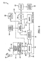
- a system for changing the operating frequency of a receiver is generally designated by the numeral 10, as shown in Fig. 1 of the drawings. While the present system 10 can be used to change the operating frequency of a receiver used in a variety of devices, the following discussion relates to the use of the present system 10 in association with a receiver used in a barrier operator.
- the barrier operator typically a garage door opener, is used to move an access barrier, such as a garage door, between open and closed positions.
- the system 10 could be used with other access barriers such as gates, curtains, awnings, windows and the like.
- the present system 10 generally comprises a barrier operator 12, a frequency matching module 14, and a remote transmitter 16.
- the barrier operator 12 includes an operator controller 18 which receives input signals and generates output signals to control the various functions of the components associated with the barrier operator.
- the operator controller 18 is a logic control that may be implemented using a general purpose, or application specific semiconductor based microprocessor/microcontroller that provides the necessary hardware, software, and storage to carry out the desired functions.
- Coupled to the operator controller 18 is a memory 20.
- the memory 20 allows the operator controller 18 to store and retrieve operating data as it is needed for the controller 18 to function.
- the memory 20 may be comprised of non-volatile memory, such as EEPROM, flash memory, or ROM, or other memory of a suitable capacity to provide for the operation of the barrier operator 12. It will be appreciated that the memory may be maintained internally in the controller. Coupled to the memory 20, and to the operator controller 18, is a power interface 22. The power interface 22 assists in coordinating the various inputs and outputs of the components connected to the barrier operator 12 and the operator controller 18. Additionally, the power interface 22 receives power supplied by a mains power source 24, and transforms it into a power form, AC or DC, that is compatible for use with the components of the barrier operator 12. As used in the present discussion, mains power is defined as standard commercial or residential power, such as 120VAC for example.
- the power interface 22 also allows the barrier operator 12 to communicate with a motor 26 and a wall station 28, as well as any other sensor or device that may be contemplated.
- the wall station 28 is coupled to the power interface 22 via a wired connection, and allows the user to control various aspects of the barrier operator's 12 operation via the operator controller 18, such as the direction of motor shaft rotation.
- the wall station 28 may communicate with the controller 18 by wireless signals, including RF, infrared or ultrasonic.
- the motor 26 may comprise any type of electric motor (AC or DC) that is compatible with the power (AC or DC) being supplied by the power interface 22.
- linkage 30 Connected to the motor 26 is linkage 30, which allows the motor 26 to move an access barrier 32, such as a garage door, between open and closed positions.
- the linkage 30 may be comprised of a counter-balancing system used to assist in moving the barrier 32 between open and closed positions.
- the linkage 30 may be part of a header-mounted, trolley type, screw drive, jackshaft or any other mechanism used to assist in moving the access barrier 32 between limit positions.
- a receiver 34 is connected to the barrier operator 12 and in particular to the operator controller 18.
- the receiver 34 is capable of receiving wireless signals, and allows the wireless transmitter 16 to send function requests to the barrier operator on a predetermined RF carrier frequency.
- the wireless transmissions generated by the transmitter 16 will likely be encrypted with a rolling code or related technology.
- the transmitted function request allows a user to control various operations of the barrier operator 12, including, for example, the opening and closing of the access barrier 32.
- the frequency matching module 14 is connected to the receiver 34 by a signal line 36 and a selection interface, such as a frequency select line 38.
- the connections between the module 14 and receiver 34 may be hardwired connections.
- a connector or connectors 40 may be provided.
- the connectors 40 may be of a snap-type, pin-type, plug-type, edge connector-type or any other suitable electronics connector that would allow the frequency matching module 14 to be connected to the receiver 34.
- the module 14 contains an internal antenna, such as a printed circuit board antenna (not shown), or an external antenna 42.
- the antenna 42 allows the matching module to receive transmitted function requests from the transmitter 16, so that such signals can be further optimized, then passed to the receiver 34, via the signal line 36, as will be discussed more fully below. It is also contemplated that any suitable internal or external antenna suitable for the present system may be used.
- the receiver 34 may include a receiver antenna 43, with the receiver 34 being sensitive to signals of an initial operating frequency.
- transmitted signals sent by the wireless transmitter 16 or wall station 28 on this initial frequency would be received by the receiver 34 via the receiver antenna 43.
- the antenna 42 of the matching module 14 is configured to override the receiver antenna 43.
- signals transmitted by the wireless transmitter 16 or wall station 28 are received by the antenna 42 of the matching module 14, where the signal is processed in a manner to be discussed, and passed on to the receiver 34 via the signal line 36 where it is interpreted.
- the receiver 34 may be configured to utilize only the antenna 42 provided by a connected matching module 14. That is, the receiver 34, standing alone, without an attached matching module 14, would not be capable of detecting a transmitted signal. Thus, when the antenna 42 of the matching module 14 detects a transmitted signal, the signal is processed in a manner to be discussed, and is then passed on to the receiver 34 via the signal line 36 where it is interpreted.
- the frequency matching module 14 comprises the necessary hardware and software, to allow the module 14 to carry out the functions to be described.
- the frequency matching module 14 is configured, such that, when the matching module 14 sends a selection input, such as a control signal, via the frequency select line 38, the receiver 34 becomes sensitive to signals of a new carrier frequency. That is, the receiver's operating frequency changes to another operating frequency as determined by the matching module 14, when the module 14 sends a control signal to the receiver 34 on the frequency select line 38.
- the matching modules 14 will have a range of operating frequencies that each module can enable at the receiver 34. For example, one matching module 14 may enable operating frequency A at the receiver, while a second matching module 14 may enable operating frequency B at the receiver, and so on.
- each matching module 14 may allow the user to invoke a range of operating frequencies at the receiver 34, without having to replace the module 14 to enable a new operating frequency at the receiver 34.
- replacement of a module may allow use of a select band of frequencies or multiple bands of frequency as long as the bands are contiguous.
- the matching module 14 is also capable of optimizing the signals sent to the receiver 34, which will be discussed below.
- the user selects a matching module 14 that enables an operating frequency at the receiver 34 that has reduced interference. Additionally, a transmitter 16 is selected that has the same operating frequency as the receiver 34, thus allowing the user to send function requests to the barrier operator 12 on the newly selected operating frequency.
- the matching module 14 performs an optimization on all incoming signals that are of the same frequency as the operating frequency of the receiver 34. Specifically, the matching module 14 takes the signal received by the internal or external antenna 42 and optimizes the transmitted signal to provide enhanced output to the receiver 34, via the signal line 36.
- the matching module 14 may include, utilizing a frequency tuning network 45, whereby the values of the network's components comprising capacitors and inductors, are chosen based on the selected operating frequency of the receiver 34.
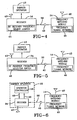
- the tuning network 45 may comprise one or more inductors and/or one or more capacitors, and may take on a number of known tuning network topologies or designs. Two such tuning network topologies or designs are shown in Figs.
- the tuning network 45 shown in Fig. 2 comprises impedance elements Z1 60, Z2 62, and Z3 64 that are arranged and connected in a Pi-type configuration.
- a network input 66 and a network output 68 are provided, to allow signals to pass through the tuning network 45.
- the impedance values for these impedance elements 60-64 may comprise any suitable value, and may be realized from either inductors or capacitors or a combination of both.
- the frequency matching network 45 shown in Fig. 3 comprises impedance elements Z1 60, and Z2 62 that are arranged and connected in a typical L-type configuration.
- a network input 66 and a network output 68 are provided, to allow signals to pass through the tuning network 45.
- the values for these impedance elements 60, 62 may comprise any suitable value, and may be realized from either inductors or capacitors or a combination of both. As a result of these optimization techniques, the RF energy of a transmitted signal is efficiently captured, and the signal output created by the optimizing action of the matching module 14 is enhanced, allowing the receiver 34 to detect signals transmitted by the wireless transmitter 16 from a greater distance or range than the receiver 34 would be able to otherwise.
- Fig. 4 shows an alternative embodiment of the system 10, whereby the operating frequency of the receiver 34 is changed via a selection interface, such as a frequency selection jumper or jumpers 44 provided by the receiver 34.
- a selection interface such as a frequency selection jumper or jumpers 44 provided by the receiver 34.
- the term jumper refers to a lead wire that is moveable between terminals extending from circuitry provided by the receiver. Access to this jumper 44 may be provided through an opening or window cut-out within the barrier operator 12, or the jumper 44 may be provided externally on the barrier operator 12. Other arrangements and locations for the jumper 44 are also contemplated, such that the user may easily access the jumper 44.
- a matching module 14 which is configured to optimize the selected operating frequency of the receiver is selected, as discussed with regard to the embodiment of Fig. 1 .
- the user couples the module 14 to the receiver 34 via signal line 36.
- the connector 40 may be used to allow a user to easily attach and remove the matching module 14, as discussed with respect to Fig. 1 .
- the matching module 14, because it is specifically configured for use with the receiver's operating frequency, as discussed with respect to Fig. 1 is able to receive the signal transmitted by the transmitter 16, via external antenna 42. This optimizes the received signal in a manner to provide the receiver 34 with a greater range of signal detection, than would occur otherwise.
- the optimized signal is then passed to the receiver 34 via the signal line 36.
- the antenna 42 may also be internal to the matching module 14.
- a further embodiment of the system 10 is shown in Fig. 5 , and while functionally equivalent to the embodiment disclosed with respect to Fig. 1 , the operating frequency of the receiver 34 of the present embodiment is changed through a selection interface, such as a multi-position switch 46. After the switch 46 is set to a new position, indicating a new frequency or band of frequencies, the user then selects a matching module 14 that is configured to optimize frequencies that include the selected operating frequency of the receiver, as discussed with respect to Fig. 1 . The module 14 optimizes incoming signals sent by the transmitter 16 and passes the signals to the receiver via the signal line 36 for processing. As a result, the receiver 34 achieves an extended range of signal detection or reception.
- a selection interface such as a multi-position switch 46.
- the antenna 42 may be external as shown, or may be internal to the matching module 14, as described with respect to Fig. 1 and 4 . It is also contemplated that the frequency selection switch 46 may be comprised of a push-button type, rotary type, slide-type, or any other type of switch suitable for such application.
- the operating frequency of the receiver 34 is changed in response to a signal sent by the operator controller 18.
- the operator controller 18 is connected to the receiver 34 by a selection interface such as a receiver select line 48 and a receiver output line 50, that allows the receiver and operator controller to communicate.
- the operator controller 18 contains the necessary software or logic that, when initiated, causes the operator controller 18 to send a selection input, such as a control signal, to the receiver 34 via the receiver select line 48.
- a selection input such as a control signal
- the receiver 34 changes its initial operating frequency to another operating frequency.
- the initiation of the control signal can be initiated through various input mechanisms.
- the initiation of the program may take place in a variety of manners, for example, a user may be required to depress a specific sequence of buttons on the transmitter 16 or wall station 28, which causes the operator controller 18 to send a control signal to the receiver 34 initiating a change of its operating frequency.
- Other methods of causing the operator controller 18 to send a control signal to the receiver 34 are contemplated, and include the operator controller 18 detecting interference with a transmitted signal, and in response dynamically sending a signal to the receiver 34 to change its frequency of operation.
- the user couples to the receiver 34, a matching module 14 configured for use with the selected operating frequency of the receiver 34, via the signal line 36.
- the matching module 14 receives and optimizes incoming signals sent from the transmitter 16, as discussed with the embodiment of Fig. 1 . It is also contemplated that the matching module 14 may be removably attached to the receiver 34 using connectors 40, as discussed with respect to the embodiments of Figs. 1 , 4, and 5 .
- Fig. 7 shows the present system 10 installed in a typical configuration.
- the barrier operator 12 is affixed to a wall or other suitable surface.
- the access barrier 32 Connected to the barrier operator 12, via the linkage 30, is the access barrier 32 that is a garage door in this case.
- the linkage 30 may comprise the systems discussed with respect to Fig. 1 .
- Attached to the barrier operator 12 is the frequency select module 14. As discussed with respect to Fig. 1 , the frequency select module 14, allows a user to change the operating frequency of the receiver 34. Thus, the user may directly access the module 14 directly without the need to disassemble the barrier operator 12.
- one advantage of one or more embodiments of the present system is that a user can easily change the operating frequency of the receiver in a barrier operator, without the expense or need of a technician. Still another advantage of the present system is that the newly selected operating frequency of the receiver can be easily optimized by selecting the appropriate matching module. Yet another advantage of the present system is that the receiver's operating frequency can be changed without resort to total replacement of the receiver itself, as a result, the cost associated with changing the frequency of the receiver is reduced. Another advantage of the present system is that the receiver's range of detection is increased by changing the operating frequency of the receiver to another frequency with reduced interference, and by optimizing the received signal.
Abstract
Description
- Generally, the present invention relates to a frequency matching and optimization system that allows a radio frequency (RF) receiver to change operating frequencies, while optimizing the received signal for processing by the receiver. More particularly, the present invention pertains to a user interchangeable frequency matching and optimization system that can be easily installed. More specifically, the present invention relates to a user interchangeable frequency matching and optimization system for a receiver used in a barrier operator, such as a garage door opener.
- In general, wireless receivers and transmitters use a signal having a predetermined carrier frequency to allow the transmitter and receiver to communicate information. However, because of signal interference, the selected carrier frequency often becomes noisy, making it difficult or impossible for the receiver to accurately interpret the information transmitted within the carrier frequency. This interference may arise due to a variety of factors, including noise and other signals being in the same frequency range or band as the selected carrier signal.
- One instance where interference with the transmitted carrier signal is a concern is in the operation of transmitters and receivers used with barrier operators, such as a garage door opener. Typically, when a user purchases and installs a barrier operator, he or she may determine that the receiver has a limited range of reception due to interference of the wireless transmitter's carrier signal. While this problem can be overcome by changing the operating frequency of the receiver and transmitter, it is a highly technical affair, typically requiring the physical disassembly of the barrier operator, and the replacement of the components comprising the receiver. And, of course, purchase of a new transmitter. Furthermore, most users of barrier operators do not have the required technical skill or available time to undertake such an endeavor. As a result, a technician may be required to perform the work, although an inherent risk still exists that the technician may damage the barrier operator during the completion of such work.
Alternatively, the user may remove and exchange the barrier operator for another barrier operator that operates on a different carrier frequency not subject to substantial interference. However, these solutions require the user to expend substantial time, effort, and resources to achieve the optimal result. - Further, in typical circumstances, when the operating frequency of the receiver is changed, a matching network originally used with the receiver is unaltered. The receiver's matching network, or "front end" is tuned for the operating frequency of the receiver, and is responsible for efficiently capturing the RF energy of the signal sent by the remote transmitter. However, if the matching network used is not tuned for the same operating frequency as the receiver, the RF energy within the carrier signal is not optimally captured, and the receiver's ability to detect a transmitted signal at a distance, or reception range is reduced.
- Therefore, there is a need for a frequency matching module, that allows a user to easily change the operating frequency of the barrier operator's receiver, without the need of a technician. Furthermore, there is a need for a plurality of frequency matching modules corresponding to a variety of carrier operating frequencies, allowing the user to select the best operating frequency for his or her barrier operator's operating environment, thereby extending the receiver's range of reception. Additionally, there is a need for a matching module that can also optimize a signal transmitted in the receiver's frequency of operation.
- In light of the foregoing, it is a first aspect of the present invention to provide a frequency matching and optimization system comprising: a barrier operator having a receiver responsive to a carrier signal of a first frequency; a frequency matching module to optimize a received carrier signal of a second frequency, said module removably coupled to said barrier operator; whereby in response to coupling said module to said barrier operator, said receiver becomes responsive to said second frequency.
- In one embodiment of the invention, the barrier operator has a selection interface to receive a selection input; said receiver is configured to detect signals of said second frequency in response to said selection input at said selection interface; and said frequency matching module has an antenna to receive signals, whereby said frequency matching module optimizes signals of said second frequency, which are detected by said receiver.
- A system according to the invention may comprise a plurality of frequency matching modules; wherein said receiver is removably coupled to a first frequency matching module, said frequency matching module enabling receiver to be responsive to said signals of a first predetermined frequency; and the receiver is selectively enabled to be responsive to signals of said second predetermined frequency upon the removal of said first frequency matching module, and the coupling of a second frequency matching module to said receiver.
- This and other features and advantages of the present invention will become better understood with regard to the following description, appended claims, and accompanying drawings wherein:
-
Fig. 1 is a block diagram of a barrier operator with connected frequency matching module according to the present invention; -
Fig. 2 is a block diagram of an alternative frequency tuning network; -
Fig. 3 is a block diagram of another alternative frequency tuning network; -
Fig. 4 is a block diagram of an alternative embodiment of the present invention where a receiver's operating frequency is changed by setting a frequency selection jumper; -
Fig. 5 is a block diagram of another embodiment of the present invention where a receiver's operating frequency is changed by a frequency select switch; -
Fig. 6 is a block diagram of a further embodiment of the present invention where a receiver's operating frequency is changed by an operator controller of the barrier operator; and -
Fig. 7 is a perspective view of a mounted barrier operator with matching module and a mounted access barrier. - A system for changing the operating frequency of a receiver, is generally designated by the
numeral 10, as shown inFig. 1 of the drawings. While thepresent system 10 can be used to change the operating frequency of a receiver used in a variety of devices, the following discussion relates to the use of thepresent system 10 in association with a receiver used in a barrier operator. The barrier operator, typically a garage door opener, is used to move an access barrier, such as a garage door, between open and closed positions. Of course, thesystem 10 could be used with other access barriers such as gates, curtains, awnings, windows and the like. - The
present system 10 generally comprises abarrier operator 12, afrequency matching module 14, and aremote transmitter 16. Thebarrier operator 12 includes anoperator controller 18 which receives input signals and generates output signals to control the various functions of the components associated with the barrier operator. Specifically, theoperator controller 18 is a logic control that may be implemented using a general purpose, or application specific semiconductor based microprocessor/microcontroller that provides the necessary hardware, software, and storage to carry out the desired functions. Coupled to theoperator controller 18 is amemory 20. Thememory 20 allows theoperator controller 18 to store and retrieve operating data as it is needed for thecontroller 18 to function. It is contemplated that thememory 20 may be comprised of non-volatile memory, such as EEPROM, flash memory, or ROM, or other memory of a suitable capacity to provide for the operation of thebarrier operator 12. It will be appreciated that the memory may be maintained internally in the controller. Coupled to thememory 20, and to theoperator controller 18, is apower interface 22. Thepower interface 22 assists in coordinating the various inputs and outputs of the components connected to thebarrier operator 12 and theoperator controller 18. Additionally, thepower interface 22 receives power supplied by amains power source 24, and transforms it into a power form, AC or DC, that is compatible for use with the components of thebarrier operator 12. As used in the present discussion, mains power is defined as standard commercial or residential power, such as 120VAC for example. However, it is contemplated that thepresent system 10 may be easily modified, using known techniques, to operate with non-standard power. Thepower interface 22 also allows thebarrier operator 12 to communicate with amotor 26 and awall station 28, as well as any other sensor or device that may be contemplated. Thewall station 28 is coupled to thepower interface 22 via a wired connection, and allows the user to control various aspects of the barrier operator's 12 operation via theoperator controller 18, such as the direction of motor shaft rotation. Although shown as a wired device, it will be appreciated that thewall station 28 may communicate with thecontroller 18 by wireless signals, including RF, infrared or ultrasonic. Themotor 26 may comprise any type of electric motor (AC or DC) that is compatible with the power (AC or DC) being supplied by thepower interface 22. Connected to themotor 26 islinkage 30, which allows themotor 26 to move anaccess barrier 32, such as a garage door, between open and closed positions. Thelinkage 30 may be comprised of a counter-balancing system used to assist in moving thebarrier 32 between open and closed positions. Thelinkage 30 may be part of a header-mounted, trolley type, screw drive, jackshaft or any other mechanism used to assist in moving theaccess barrier 32 between limit positions. - A
receiver 34 is connected to thebarrier operator 12 and in particular to theoperator controller 18. Thereceiver 34 is capable of receiving wireless signals, and allows thewireless transmitter 16 to send function requests to the barrier operator on a predetermined RF carrier frequency. The wireless transmissions generated by thetransmitter 16 will likely be encrypted with a rolling code or related technology. The transmitted function request allows a user to control various operations of thebarrier operator 12, including, for example, the opening and closing of theaccess barrier 32. Thefrequency matching module 14 is connected to thereceiver 34 by asignal line 36 and a selection interface, such as a frequencyselect line 38. The connections between themodule 14 andreceiver 34 may be hardwired connections. To allow a user to easily remove or connect thefrequency matching module 14 to thereceiver 34, a connector orconnectors 40 may be provided. Theconnectors 40 may be of a snap-type, pin-type, plug-type, edge connector-type or any other suitable electronics connector that would allow thefrequency matching module 14 to be connected to thereceiver 34. Additionally, themodule 14 contains an internal antenna, such as a printed circuit board antenna (not shown), or anexternal antenna 42. Theantenna 42 allows the matching module to receive transmitted function requests from thetransmitter 16, so that such signals can be further optimized, then passed to thereceiver 34, via thesignal line 36, as will be discussed more fully below. It is also contemplated that any suitable internal or external antenna suitable for the present system may be used. - Furthermore, it is contemplated that the
receiver 34 may include areceiver antenna 43, with thereceiver 34 being sensitive to signals of an initial operating frequency. Thus, transmitted signals sent by thewireless transmitter 16 orwall station 28 on this initial frequency would be received by thereceiver 34 via thereceiver antenna 43. However, if the user decides to connect amatching module 14 to thereceiver 34 in accordance with the discussion above, theantenna 42 of thematching module 14 is configured to override thereceiver antenna 43. As a result, signals transmitted by thewireless transmitter 16 orwall station 28 are received by theantenna 42 of thematching module 14, where the signal is processed in a manner to be discussed, and passed on to thereceiver 34 via thesignal line 36 where it is interpreted. - Alternatively, instead of providing each
receiver 34 with areceiver antenna 43, it is contemplated that thereceiver 34 may be configured to utilize only theantenna 42 provided by aconnected matching module 14. That is, thereceiver 34, standing alone, without an attachedmatching module 14, would not be capable of detecting a transmitted signal. Thus, when theantenna 42 of thematching module 14 detects a transmitted signal, the signal is processed in a manner to be discussed, and is then passed on to thereceiver 34 via thesignal line 36 where it is interpreted. - The
frequency matching module 14 comprises the necessary hardware and software, to allow themodule 14 to carry out the functions to be described. Briefly, thefrequency matching module 14 is configured, such that, when thematching module 14 sends a selection input, such as a control signal, via the frequencyselect line 38, thereceiver 34 becomes sensitive to signals of a new carrier frequency. That is, the receiver's operating frequency changes to another operating frequency as determined by thematching module 14, when themodule 14 sends a control signal to thereceiver 34 on the frequencyselect line 38. It is also contemplated that the matchingmodules 14 will have a range of operating frequencies that each module can enable at thereceiver 34. For example, onematching module 14 may enable operating frequency A at the receiver, while asecond matching module 14 may enable operating frequency B at the receiver, and so on. Furthermore, each matchingmodule 14 may allow the user to invoke a range of operating frequencies at thereceiver 34, without having to replace themodule 14 to enable a new operating frequency at thereceiver 34. In other words, replacement of a module may allow use of a select band of frequencies or multiple bands of frequency as long as the bands are contiguous. In addition to altering the operating frequency of thereceiver 34, thematching module 14 is also capable of optimizing the signals sent to thereceiver 34, which will be discussed below. - During normal use, when the
receiver 34 experiences reduced reception range from thetransmitter 16 due to interference of the transmitted signal, the user selects amatching module 14 that enables an operating frequency at thereceiver 34 that has reduced interference. Additionally, atransmitter 16 is selected that has the same operating frequency as thereceiver 34, thus allowing the user to send function requests to thebarrier operator 12 on the newly selected operating frequency. Once thematching module 14 has initiated a change in the receiver's 34 operating frequency, thematching module 14 performs an optimization on all incoming signals that are of the same frequency as the operating frequency of thereceiver 34. Specifically, thematching module 14 takes the signal received by the internal orexternal antenna 42 and optimizes the transmitted signal to provide enhanced output to thereceiver 34, via thesignal line 36. - Although other methods may be used to optimize the signal received by the
matching module 14, one exemplary method of carrying out this optimization is by changing the effective length of the external antenna 42 (or internal antenna), based on the chosen operating frequency of thereceiver 34. Yet another technique used by thematching module 14 to optimize an incoming signal may include, utilizing afrequency tuning network 45, whereby the values of the network's components comprising capacitors and inductors, are chosen based on the selected operating frequency of thereceiver 34. Specifically, thetuning network 45, may comprise one or more inductors and/or one or more capacitors, and may take on a number of known tuning network topologies or designs. Two such tuning network topologies or designs are shown inFigs. 2 and 3 , which comprise a Pi-matching network and an L-network (L-matching network) respectively. Thetuning network 45 shown inFig. 2 comprisesimpedance elements Z1 60,Z2 62, andZ3 64 that are arranged and connected in a Pi-type configuration. Anetwork input 66 and anetwork output 68 are provided, to allow signals to pass through thetuning network 45. The impedance values for these impedance elements 60-64 may comprise any suitable value, and may be realized from either inductors or capacitors or a combination of both. Thefrequency matching network 45 shown inFig. 3 comprisesimpedance elements Z1 60, andZ2 62 that are arranged and connected in a typical L-type configuration. Anetwork input 66 and anetwork output 68 are provided, to allow signals to pass through thetuning network 45. The values for theseimpedance elements matching module 14 is enhanced, allowing thereceiver 34 to detect signals transmitted by thewireless transmitter 16 from a greater distance or range than thereceiver 34 would be able to otherwise. -
Fig. 4 shows an alternative embodiment of thesystem 10, whereby the operating frequency of thereceiver 34 is changed via a selection interface, such as a frequency selection jumper orjumpers 44 provided by thereceiver 34. As used herein, the term jumper refers to a lead wire that is moveable between terminals extending from circuitry provided by the receiver. Access to thisjumper 44 may be provided through an opening or window cut-out within thebarrier operator 12, or thejumper 44 may be provided externally on thebarrier operator 12. Other arrangements and locations for thejumper 44 are also contemplated, such that the user may easily access thejumper 44. Once the operating frequency of the receiver is changed by the new jumper selection input, such as a new jumper setting, amatching module 14 which is configured to optimize the selected operating frequency of the receiver is selected, as discussed with regard to the embodiment ofFig. 1 . Once anappropriate module 14 is selected, the user then couples themodule 14 to thereceiver 34 viasignal line 36. Furthermore, theconnector 40 may be used to allow a user to easily attach and remove thematching module 14, as discussed with respect toFig. 1 . Thematching module 14, because it is specifically configured for use with the receiver's operating frequency, as discussed with respect toFig. 1 is able to receive the signal transmitted by thetransmitter 16, viaexternal antenna 42. This optimizes the received signal in a manner to provide thereceiver 34 with a greater range of signal detection, than would occur otherwise. The optimized signal is then passed to thereceiver 34 via thesignal line 36. It should also be appreciated that theantenna 42 may also be internal to thematching module 14. - Still a further embodiment of the
system 10 is shown inFig. 5 , and while functionally equivalent to the embodiment disclosed with respect toFig. 1 , the operating frequency of thereceiver 34 of the present embodiment is changed through a selection interface, such as amulti-position switch 46. After theswitch 46 is set to a new position, indicating a new frequency or band of frequencies, the user then selects amatching module 14 that is configured to optimize frequencies that include the selected operating frequency of the receiver, as discussed with respect toFig. 1 . Themodule 14 optimizes incoming signals sent by thetransmitter 16 and passes the signals to the receiver via thesignal line 36 for processing. As a result, thereceiver 34 achieves an extended range of signal detection or reception. Theantenna 42 may be external as shown, or may be internal to thematching module 14, as described with respect toFig. 1 and4 . It is also contemplated that thefrequency selection switch 46 may be comprised of a push-button type, rotary type, slide-type, or any other type of switch suitable for such application. - Yet another embodiment of the
system 10 is described inFig. 6 , and while still functionally equivalent to the embodiment shown inFig.1 , the operating frequency of thereceiver 34 is changed in response to a signal sent by theoperator controller 18. Here, theoperator controller 18 is connected to thereceiver 34 by a selection interface such as a receiverselect line 48 and areceiver output line 50, that allows the receiver and operator controller to communicate. Theoperator controller 18 contains the necessary software or logic that, when initiated, causes theoperator controller 18 to send a selection input, such as a control signal, to thereceiver 34 via the receiverselect line 48. As a result of the receipt of the control signal, thereceiver 34 changes its initial operating frequency to another operating frequency. The initiation of the control signal can be initiated through various input mechanisms. For example, the initiation of the program may take place in a variety of manners, for example, a user may be required to depress a specific sequence of buttons on thetransmitter 16 orwall station 28, which causes theoperator controller 18 to send a control signal to thereceiver 34 initiating a change of its operating frequency. Other methods of causing theoperator controller 18 to send a control signal to thereceiver 34 are contemplated, and include theoperator controller 18 detecting interference with a transmitted signal, and in response dynamically sending a signal to thereceiver 34 to change its frequency of operation. After the receiver's 34 frequency has been changed, the user then couples to thereceiver 34, amatching module 14 configured for use with the selected operating frequency of thereceiver 34, via thesignal line 36. Thematching module 14 receives and optimizes incoming signals sent from thetransmitter 16, as discussed with the embodiment ofFig. 1 . It is also contemplated that thematching module 14 may be removably attached to thereceiver 34 usingconnectors 40, as discussed with respect to the embodiments ofFigs. 1 ,4, and 5 . -
Fig. 7 shows thepresent system 10 installed in a typical configuration. Here, thebarrier operator 12 is affixed to a wall or other suitable surface. Connected to thebarrier operator 12, via thelinkage 30, is theaccess barrier 32 that is a garage door in this case. Thelinkage 30 may comprise the systems discussed with respect toFig. 1 . Attached to thebarrier operator 12 is the frequencyselect module 14. As discussed with respect toFig. 1 , the frequencyselect module 14, allows a user to change the operating frequency of thereceiver 34. Thus, the user may directly access themodule 14 directly without the need to disassemble thebarrier operator 12. - It will, therefore, be appreciated that one advantage of one or more embodiments of the present system is that a user can easily change the operating frequency of the receiver in a barrier operator, without the expense or need of a technician. Still another advantage of the present system is that the newly selected operating frequency of the receiver can be easily optimized by selecting the appropriate matching module. Yet another advantage of the present system is that the receiver's operating frequency can be changed without resort to total replacement of the receiver itself, as a result, the cost associated with changing the frequency of the receiver is reduced. Another advantage of the present system is that the receiver's range of detection is increased by changing the operating frequency of the receiver to another frequency with reduced interference, and by optimizing the received signal.
- Although the present invention has been described in considerable detail with reference to certain embodiments, other embodiments are possible, within the scope of the appended claims.
Claims (15)
- A frequency matching and optimization system (10) comprising:a barrier operator (12) having a receiver (34) responsive to a carrier signal of a first frequency;a frequency matching module (14) to optimize a received carrier signal of a second frequency, said module removably coupled to said barrier operator;whereby in response to coupling said module to said barrier operator, said receiver becomes responsive to said second frequency.
- The system according to claim 1 in which the barrier operator has a selection interface to receive a selection input; and wherein:said receiver is configured to detect signals of said second frequency in response to said selection input at said selection interface; andsaid frequency matching module has an antenna (42) to receive signals, whereby said frequency matching module optimizes signals of said second frequency, which are detected by said receiver.
- The system according to claim 2, wherein said selection interface comprises a selection jumper (44).
- The system according to claim 2, wherein said selection interface comprises a frequency selection switch (46).
- The system according to claim 2, wherein said selection interface comprises an operator controller (18) coupled to said barrier operator and a receiver select line coupling said receiver with said operator controller.
- The system according to claim 5, wherein said selection input comprises a control signal.
- The system according to any of claims 2 to 6, wherein said frequency matching module is removably coupled to said receiver by a connector (40).
- The system according to any of claims 2 to 7, wherein said antenna is of a length suitable to optimize the RF energy contained in a transmitted signal of said desired frequency.
- The system according to claim 7, wherein said antenna is external to said matching module.
- The system according to claim 8, wherein said antenna is internal to said matching module.
- The system according to any of claims 2 to 10, wherein said frequency matching module comprises a frequency tuning network (45) to optimize signals of said desired frequency.
- The system according to claim 11, wherein said frequency tuning network comprises an operatively arranged network of capacitors and inductors.
- The system according to claim 12, wherein said operatively arranged network comprises a Pi configuration.
- The system according to claim 12, wherein said operatively arranged network comprises an L configuration.
- A system as claimed in any preceding claim comprising:a plurality of frequency matching modules; wherein:said receiver is removably coupled to a first frequency matching module, said frequency matching module enabling receiver to be responsive to said signals of a first predetermined frequency; andthe receiver is selectively enabled to be responsive to signals of said second predetermined frequency upon the removal of said first frequency matching module; and the coupling of a second frequency matching module to said receiver.
Applications Claiming Priority (2)
| Application Number | Priority Date | Filing Date | Title |
|---|---|---|---|
| US11/104,945 US7376401B2 (en) | 2005-04-12 | 2005-04-12 | Frequency matching and optimization system for an RF receiver |
| PCT/US2006/006564 WO2006112950A1 (en) | 2005-04-12 | 2006-02-22 | Frequency matching and optimization system for an rf receiver |
Publications (2)
| Publication Number | Publication Date |
|---|---|
| EP1869646A1 EP1869646A1 (en) | 2007-12-26 |
| EP1869646B1 true EP1869646B1 (en) | 2009-04-22 |
Family
ID=36405952
Family Applications (1)
| Application Number | Title | Priority Date | Filing Date |
|---|---|---|---|
| EP06735998A Active EP1869646B1 (en) | 2005-04-12 | 2006-02-22 | Frequency matching and optimization system for an rf receiver |
Country Status (6)
| Country | Link |
|---|---|
| US (1) | US7376401B2 (en) |
| EP (1) | EP1869646B1 (en) |
| AT (1) | ATE429691T1 (en) |
| CA (1) | CA2603053A1 (en) |
| DE (1) | DE602006006431D1 (en) |
| WO (1) | WO2006112950A1 (en) |
Families Citing this family (4)
| Publication number | Priority date | Publication date | Assignee | Title |
|---|---|---|---|---|
| US7952464B2 (en) * | 2006-10-05 | 2011-05-31 | Intermec Ip Corp. | Configurable RFID tag with protocol and band selection |
| US20080280574A1 (en) * | 2007-05-11 | 2008-11-13 | Broadcom Corporation, A California Corporation | RF transmitter with adjustable antenna assembly |
| US8957766B2 (en) * | 2009-08-06 | 2015-02-17 | Gallen Ka Leung Tsui | Universal transmitter |
| DE102013114223B4 (en) * | 2013-12-06 | 2021-08-05 | Hörmann KG Antriebstechnik | REMOTE CONTROLLED DOOR OR DRIVE DEVICE WITH MAGNETIC ANTENNA |
Family Cites Families (14)
| Publication number | Priority date | Publication date | Assignee | Title |
|---|---|---|---|---|
| DE7804106U1 (en) | 1978-02-13 | 1978-06-15 | Hoermann Kg Antriebs- Und Steuerungstechnik, 4834 Harsewinkel | HAND TRANSMITTER FOR TWO DIFFERENT SIGNALS |
| US5812066A (en) * | 1995-08-16 | 1998-09-22 | Terk Technologies Corporation | Antenna tuning control circuit |
| GB2315892B (en) | 1996-07-26 | 1998-06-24 | Prince Corp | Multiple frequency transmitter |
| US6032209A (en) | 1998-07-24 | 2000-02-29 | Storage Technology Corporation | Hot-swappable high speed point-to-point interface |
| US6249673B1 (en) * | 1998-11-09 | 2001-06-19 | Philip Y. W. Tsui | Universal transmitter |
| US6978126B1 (en) * | 1999-06-07 | 2005-12-20 | Johnson Controls Technology Company | Transceiver with closed loop control of antenna tuning and power level |
| US6915146B1 (en) | 2000-04-25 | 2005-07-05 | The Chamberlain Group, Inc. | Method and apparatus for receiving a plurality of different codes at a plurality of different frequencies |
| US6847303B2 (en) | 2001-05-07 | 2005-01-25 | Marantec America Corporation | Multifrequency garage door opener |
| US6667723B2 (en) | 2001-07-03 | 2003-12-23 | Kyocera Wireless Corp. | System and method for a GPS enabled antenna |
| US7057494B2 (en) * | 2001-08-09 | 2006-06-06 | Fitzgibbon James J | Method and apparatus for a rolling code learning transmitter |
| KR20040067906A (en) * | 2003-01-21 | 2004-07-30 | 소니 가부시끼 가이샤 | Flat antenna, antenna unit and broadcast reception terminal apparatus |
| US20050088281A1 (en) * | 2003-10-27 | 2005-04-28 | Rohrberg Timothy K. | Miniature remote control system |
| US7525489B2 (en) * | 2004-12-07 | 2009-04-28 | Sony Ericsson Mobile Communications Ab | Digital video broadcast-handheld (DVB-H) antennas for wireless terminals |
| JP2006246135A (en) * | 2005-03-04 | 2006-09-14 | Denso Corp | Receiver for smart entry system |
-
2005
- 2005-04-12 US US11/104,945 patent/US7376401B2/en not_active Expired - Fee Related
-
2006
- 2006-02-22 CA CA002603053A patent/CA2603053A1/en not_active Abandoned
- 2006-02-22 AT AT06735998T patent/ATE429691T1/en not_active IP Right Cessation
- 2006-02-22 EP EP06735998A patent/EP1869646B1/en active Active
- 2006-02-22 WO PCT/US2006/006564 patent/WO2006112950A1/en active Application Filing
- 2006-02-22 DE DE602006006431T patent/DE602006006431D1/en not_active Expired - Fee Related
Also Published As
| Publication number | Publication date |
|---|---|
| CA2603053A1 (en) | 2006-10-26 |
| US7376401B2 (en) | 2008-05-20 |
| ATE429691T1 (en) | 2009-05-15 |
| DE602006006431D1 (en) | 2009-06-04 |
| US20060229050A1 (en) | 2006-10-12 |
| WO2006112950A1 (en) | 2006-10-26 |
| EP1869646A1 (en) | 2007-12-26 |
Similar Documents
| Publication | Publication Date | Title |
|---|---|---|
| US10614647B2 (en) | Remote transmission of barrier status and change of status over a network | |
| US20220301373A1 (en) | Garage door system and method | |
| US7778262B2 (en) | Radio frequency multiple protocol bridge | |
| US7167076B2 (en) | Universal garage door operating system and method | |
| EP1869646B1 (en) | Frequency matching and optimization system for an rf receiver | |
| US8838021B2 (en) | Data relay for a controller | |
| US20170134244A1 (en) | Secure Remote Actuation System | |
| JP2009506631A (en) | Automatic movement system and method of access barrier initiated by mobile transmitter device | |
| GB2410589A (en) | Image recognition facilitated movable barrier | |
| CN104656510A (en) | Method and apparatus for remotely operating appliances from video interphones or shopping terminals | |
| CA3004557C (en) | Remote monitoring and control of movable barrier status | |
| US20070076645A1 (en) | Signal repeater system | |
| CN103968502A (en) | Communication Module, Multi-type Air Conditioning Apparatus Using The Same, And Control Method Thereof | |
| CN110140155B (en) | Multi-frequency device, control and/or monitoring device, related multi-frequency system and home automation installation | |
| US10608439B2 (en) | Ceiling fan with gesture induction function | |
| US7327249B1 (en) | Barrier operator system having multiple frequency receivers | |
| KR20060027728A (en) | Remote appliance control system and method in using robot cleaner | |
| MXPA05005064A (en) | Method for securing the recording mode of a home automation device. | |
| US20220285824A1 (en) | Antenna attachment for boosting or extending electromagnetic signals | |
| CN114320074B (en) | Turning door switch detection and control device, control system and control method | |
| KR100657463B1 (en) | Home network system | |
| JPH05115090A (en) | Wireless remote controller | |
| CN106709387A (en) | Vehicle in-garage monitoring system based on wireless transmission | |
| WO2007104675A1 (en) | Control system for one or more actuating systems | |
| JP2003008451A (en) | Wireless signal communication system for switching device |
Legal Events
| Date | Code | Title | Description |
|---|---|---|---|
| PUAI | Public reference made under article 153(3) epc to a published international application that has entered the european phase |
Free format text: ORIGINAL CODE: 0009012 |
|
| 17P | Request for examination filed |
Effective date: 20071001 |
|
| AK | Designated contracting states |
Kind code of ref document: A1 Designated state(s): AT BE BG CH CY CZ DE DK EE ES FI FR GB GR HU IE IS IT LI LT LU LV MC NL PL PT RO SE SI SK TR |
|
| AX | Request for extension of the european patent |
Extension state: AL BA HR MK YU |
|
| GRAP | Despatch of communication of intention to grant a patent |
Free format text: ORIGINAL CODE: EPIDOSNIGR1 |
|
| GRAS | Grant fee paid |
Free format text: ORIGINAL CODE: EPIDOSNIGR3 |
|
| GRAA | (expected) grant |
Free format text: ORIGINAL CODE: 0009210 |
|
| AK | Designated contracting states |
Kind code of ref document: B1 Designated state(s): AT BE BG CH CY CZ DE DK EE ES FI FR GB GR HU IE IS IT LI LT LU LV MC NL PL PT RO SE SI SK TR |
|
| AX | Request for extension of the european patent |
Extension state: AL BA HR MK YU |
|
| REG | Reference to a national code |
Ref country code: GB Ref legal event code: FG4D |
|
| REG | Reference to a national code |
Ref country code: CH Ref legal event code: EP |
|
| REG | Reference to a national code |
Ref country code: IE Ref legal event code: FG4D |
|
| REF | Corresponds to: |
Ref document number: 602006006431 Country of ref document: DE Date of ref document: 20090604 Kind code of ref document: P |
|
| NLV1 | Nl: lapsed or annulled due to failure to fulfill the requirements of art. 29p and 29m of the patents act | ||
| PG25 | Lapsed in a contracting state [announced via postgrant information from national office to epo] |
Ref country code: PT Free format text: LAPSE BECAUSE OF FAILURE TO SUBMIT A TRANSLATION OF THE DESCRIPTION OR TO PAY THE FEE WITHIN THE PRESCRIBED TIME-LIMIT Effective date: 20090822 Ref country code: FI Free format text: LAPSE BECAUSE OF FAILURE TO SUBMIT A TRANSLATION OF THE DESCRIPTION OR TO PAY THE FEE WITHIN THE PRESCRIBED TIME-LIMIT Effective date: 20090422 Ref country code: AT Free format text: LAPSE BECAUSE OF FAILURE TO SUBMIT A TRANSLATION OF THE DESCRIPTION OR TO PAY THE FEE WITHIN THE PRESCRIBED TIME-LIMIT Effective date: 20090422 Ref country code: ES Free format text: LAPSE BECAUSE OF FAILURE TO SUBMIT A TRANSLATION OF THE DESCRIPTION OR TO PAY THE FEE WITHIN THE PRESCRIBED TIME-LIMIT Effective date: 20090802 Ref country code: LT Free format text: LAPSE BECAUSE OF FAILURE TO SUBMIT A TRANSLATION OF THE DESCRIPTION OR TO PAY THE FEE WITHIN THE PRESCRIBED TIME-LIMIT Effective date: 20090422 |
|
| PG25 | Lapsed in a contracting state [announced via postgrant information from national office to epo] |
Ref country code: SI Free format text: LAPSE BECAUSE OF FAILURE TO SUBMIT A TRANSLATION OF THE DESCRIPTION OR TO PAY THE FEE WITHIN THE PRESCRIBED TIME-LIMIT Effective date: 20090422 Ref country code: PL Free format text: LAPSE BECAUSE OF FAILURE TO SUBMIT A TRANSLATION OF THE DESCRIPTION OR TO PAY THE FEE WITHIN THE PRESCRIBED TIME-LIMIT Effective date: 20090422 Ref country code: NL Free format text: LAPSE BECAUSE OF FAILURE TO SUBMIT A TRANSLATION OF THE DESCRIPTION OR TO PAY THE FEE WITHIN THE PRESCRIBED TIME-LIMIT Effective date: 20090422 Ref country code: LV Free format text: LAPSE BECAUSE OF FAILURE TO SUBMIT A TRANSLATION OF THE DESCRIPTION OR TO PAY THE FEE WITHIN THE PRESCRIBED TIME-LIMIT Effective date: 20090422 Ref country code: IS Free format text: LAPSE BECAUSE OF FAILURE TO SUBMIT A TRANSLATION OF THE DESCRIPTION OR TO PAY THE FEE WITHIN THE PRESCRIBED TIME-LIMIT Effective date: 20090822 Ref country code: SE Free format text: LAPSE BECAUSE OF FAILURE TO SUBMIT A TRANSLATION OF THE DESCRIPTION OR TO PAY THE FEE WITHIN THE PRESCRIBED TIME-LIMIT Effective date: 20090722 |
|
| PG25 | Lapsed in a contracting state [announced via postgrant information from national office to epo] |
Ref country code: RO Free format text: LAPSE BECAUSE OF FAILURE TO SUBMIT A TRANSLATION OF THE DESCRIPTION OR TO PAY THE FEE WITHIN THE PRESCRIBED TIME-LIMIT Effective date: 20090422 Ref country code: EE Free format text: LAPSE BECAUSE OF FAILURE TO SUBMIT A TRANSLATION OF THE DESCRIPTION OR TO PAY THE FEE WITHIN THE PRESCRIBED TIME-LIMIT Effective date: 20090422 Ref country code: CZ Free format text: LAPSE BECAUSE OF FAILURE TO SUBMIT A TRANSLATION OF THE DESCRIPTION OR TO PAY THE FEE WITHIN THE PRESCRIBED TIME-LIMIT Effective date: 20090422 Ref country code: DK Free format text: LAPSE BECAUSE OF FAILURE TO SUBMIT A TRANSLATION OF THE DESCRIPTION OR TO PAY THE FEE WITHIN THE PRESCRIBED TIME-LIMIT Effective date: 20090422 |
|
| PG25 | Lapsed in a contracting state [announced via postgrant information from national office to epo] |
Ref country code: BE Free format text: LAPSE BECAUSE OF FAILURE TO SUBMIT A TRANSLATION OF THE DESCRIPTION OR TO PAY THE FEE WITHIN THE PRESCRIBED TIME-LIMIT Effective date: 20090422 Ref country code: SK Free format text: LAPSE BECAUSE OF FAILURE TO SUBMIT A TRANSLATION OF THE DESCRIPTION OR TO PAY THE FEE WITHIN THE PRESCRIBED TIME-LIMIT Effective date: 20090422 |
|
| PLBE | No opposition filed within time limit |
Free format text: ORIGINAL CODE: 0009261 |
|
| STAA | Information on the status of an ep patent application or granted ep patent |
Free format text: STATUS: NO OPPOSITION FILED WITHIN TIME LIMIT |
|
| 26N | No opposition filed |
Effective date: 20100125 |
|
| PG25 | Lapsed in a contracting state [announced via postgrant information from national office to epo] |
Ref country code: BG Free format text: LAPSE BECAUSE OF FAILURE TO SUBMIT A TRANSLATION OF THE DESCRIPTION OR TO PAY THE FEE WITHIN THE PRESCRIBED TIME-LIMIT Effective date: 20090722 |
|
| REG | Reference to a national code |
Ref country code: CH Ref legal event code: PL |
|
| GBPC | Gb: european patent ceased through non-payment of renewal fee |
Effective date: 20100222 |
|
| PG25 | Lapsed in a contracting state [announced via postgrant information from national office to epo] |
Ref country code: GR Free format text: LAPSE BECAUSE OF FAILURE TO SUBMIT A TRANSLATION OF THE DESCRIPTION OR TO PAY THE FEE WITHIN THE PRESCRIBED TIME-LIMIT Effective date: 20090723 Ref country code: LI Free format text: LAPSE BECAUSE OF NON-PAYMENT OF DUE FEES Effective date: 20100228 Ref country code: MC Free format text: LAPSE BECAUSE OF NON-PAYMENT OF DUE FEES Effective date: 20100301 Ref country code: CH Free format text: LAPSE BECAUSE OF NON-PAYMENT OF DUE FEES Effective date: 20100228 |
|
| REG | Reference to a national code |
Ref country code: FR Ref legal event code: ST Effective date: 20101029 |
|
| PG25 | Lapsed in a contracting state [announced via postgrant information from national office to epo] |
Ref country code: FR Free format text: LAPSE BECAUSE OF NON-PAYMENT OF DUE FEES Effective date: 20100301 Ref country code: IE Free format text: LAPSE BECAUSE OF NON-PAYMENT OF DUE FEES Effective date: 20100222 |
|
| PG25 | Lapsed in a contracting state [announced via postgrant information from national office to epo] |
Ref country code: DE Free format text: LAPSE BECAUSE OF NON-PAYMENT OF DUE FEES Effective date: 20100901 |
|
| PG25 | Lapsed in a contracting state [announced via postgrant information from national office to epo] |
Ref country code: IT Free format text: LAPSE BECAUSE OF FAILURE TO SUBMIT A TRANSLATION OF THE DESCRIPTION OR TO PAY THE FEE WITHIN THE PRESCRIBED TIME-LIMIT Effective date: 20090422 Ref country code: GB Free format text: LAPSE BECAUSE OF NON-PAYMENT OF DUE FEES Effective date: 20100222 |
|
| PG25 | Lapsed in a contracting state [announced via postgrant information from national office to epo] |
Ref country code: CY Free format text: LAPSE BECAUSE OF FAILURE TO SUBMIT A TRANSLATION OF THE DESCRIPTION OR TO PAY THE FEE WITHIN THE PRESCRIBED TIME-LIMIT Effective date: 20090422 |
|
| PG25 | Lapsed in a contracting state [announced via postgrant information from national office to epo] |
Ref country code: LU Free format text: LAPSE BECAUSE OF NON-PAYMENT OF DUE FEES Effective date: 20100222 Ref country code: HU Free format text: LAPSE BECAUSE OF FAILURE TO SUBMIT A TRANSLATION OF THE DESCRIPTION OR TO PAY THE FEE WITHIN THE PRESCRIBED TIME-LIMIT Effective date: 20091023 |
|
| PG25 | Lapsed in a contracting state [announced via postgrant information from national office to epo] |
Ref country code: TR Free format text: LAPSE BECAUSE OF FAILURE TO SUBMIT A TRANSLATION OF THE DESCRIPTION OR TO PAY THE FEE WITHIN THE PRESCRIBED TIME-LIMIT Effective date: 20090422 |