EP3401033A1 - Molded material production method and molded material - Google Patents
Molded material production method and molded material Download PDFInfo
- Publication number
- EP3401033A1 EP3401033A1 EP17756457.2A EP17756457A EP3401033A1 EP 3401033 A1 EP3401033 A1 EP 3401033A1 EP 17756457 A EP17756457 A EP 17756457A EP 3401033 A1 EP3401033 A1 EP 3401033A1
- Authority
- EP
- European Patent Office
- Prior art keywords
- flange
- molded material
- die
- punch
- base metal
- Prior art date
- Legal status (The legal status is an assumption and is not a legal conclusion. Google has not performed a legal analysis and makes no representation as to the accuracy of the status listed.)
- Granted
Links
Images


Classifications
-
- B—PERFORMING OPERATIONS; TRANSPORTING
- B21—MECHANICAL METAL-WORKING WITHOUT ESSENTIALLY REMOVING MATERIAL; PUNCHING METAL
- B21D—WORKING OR PROCESSING OF SHEET METAL OR METAL TUBES, RODS OR PROFILES WITHOUT ESSENTIALLY REMOVING MATERIAL; PUNCHING METAL
- B21D22/00—Shaping without cutting, by stamping, spinning, or deep-drawing
- B21D22/20—Deep-drawing
- B21D22/28—Deep-drawing of cylindrical articles using consecutive dies
-
- B—PERFORMING OPERATIONS; TRANSPORTING
- B21—MECHANICAL METAL-WORKING WITHOUT ESSENTIALLY REMOVING MATERIAL; PUNCHING METAL
- B21D—WORKING OR PROCESSING OF SHEET METAL OR METAL TUBES, RODS OR PROFILES WITHOUT ESSENTIALLY REMOVING MATERIAL; PUNCHING METAL
- B21D22/00—Shaping without cutting, by stamping, spinning, or deep-drawing
- B21D22/20—Deep-drawing
- B21D22/206—Deep-drawing articles from a strip in several steps, the articles being coherent with the strip during the operation
-
- B—PERFORMING OPERATIONS; TRANSPORTING
- B21—MECHANICAL METAL-WORKING WITHOUT ESSENTIALLY REMOVING MATERIAL; PUNCHING METAL
- B21D—WORKING OR PROCESSING OF SHEET METAL OR METAL TUBES, RODS OR PROFILES WITHOUT ESSENTIALLY REMOVING MATERIAL; PUNCHING METAL
- B21D22/00—Shaping without cutting, by stamping, spinning, or deep-drawing
- B21D22/20—Deep-drawing
- B21D22/21—Deep-drawing without fixing the border of the blank
-
- B—PERFORMING OPERATIONS; TRANSPORTING
- B21—MECHANICAL METAL-WORKING WITHOUT ESSENTIALLY REMOVING MATERIAL; PUNCHING METAL
- B21D—WORKING OR PROCESSING OF SHEET METAL OR METAL TUBES, RODS OR PROFILES WITHOUT ESSENTIALLY REMOVING MATERIAL; PUNCHING METAL
- B21D22/00—Shaping without cutting, by stamping, spinning, or deep-drawing
- B21D22/20—Deep-drawing
- B21D22/22—Deep-drawing with devices for holding the edge of the blanks
Definitions
- This invention relates to a method for producing a molded material including a tubular body and a flange formed at an end portion of the body, and also relates to a molded material.
- a molded material including a tubular body and a flange formed at an end portion of the body is produced by performing a drawing process.
- the drawing process forms the body by drawing a base metal sheet, so that the thickness of the body is lower than that of the base sheet.
- a region of the metal sheet corresponding to the flange shrinks as a whole in response to the formation of the body, so that the thickness of the flange is higher than that of the base sheet.
- the base material may be referred to as a "blank”.
- the molded material as described above may be used as a motor case disclosed, for example, in patent document 1 as described below.
- the body is expected to function as a shielding material for preventing magnetic leakage to the outside of the motor case.
- the body is also expected to function as a back yoke of a stator.
- the performance of the body as the shield material or back yoke is improved as the thickness of the body increases. Therefore, when a molded material is produced by drawing, as described above, a base metal sheet with a thickness larger than the required thickness of the body is selected taking into account the reduction in thickness of the body caused by the drawing process.
- the flange is often used for mounting the motor case on a mounting object. Therefore, the flange is expected to have a certain strength.
- Patent Document 1 Japanese Patent Application Publication No. 2013-51765 A
- Non-patent Document 1 Masao Murakawa, et.al., "Basics of Plastic Processing", First Edition, SANGYO-TOSHO Publishing Co. Ltd., January 16, 1990, pp. 104 to 107
- the conventional method for producing the molded material as described above produces the molded material including the tubular body and the flange formed at the end portion of the body by the drawing process, so that the thickness of the flange is larger than that of the base sheet. For this reason, the flange may become unnecessarily thicker over a thickness required for obtaining the expected performance of the flange. This means that the molded material becomes unnecessarily heavy, which cannot be ignored in applications in which weight reduction is required, such as motor cases.
- a drawing process using a drawing sleeve may be carried out in order to prevent the wrinkles and/or buckling.
- the drawing process is carried out by sandwiching the flange between a die and the drawing sleeve, so that a tensile stress will act on the body, causing a decrease in thickness of a circumferential wall of the body.
- An object of the present invention is to provide a method for producing a molded material and the molded material, which can avoid unnecessary thickening of the flange, reduce a weight of the molded material and achieve size reduction of the base metal sheet.
- the present invention relates to a method for producing a molded material, the molded material comprising a tubular body and a flange formed at an end portion of the body, the molded material being produced by performing at least two molding processes on a base metal sheet, wherein the at least two molding processes comprise at least one drawing-out process and at least one drawing process performed after the drawing-out process; wherein the drawing-out process is carried out using a mold that comprises a punch and a die having a pushing hole; wherein a width of the punch on a rear end side is wider than a width of the punch on a distal end side so that when the punch is pushed into the pushing hole of the die, a clearance between the die and the punch is narrower on the rear end side than on the distal end side; and wherein an ironing process is performed on a region corresponding to the flange of the base metal sheet by pushing the base metal sheet together with the punch into the pushing hole in the drawing-out process.
- the drawing process is carried out using a mold comprising a die and a drawing sleeve, and in the drawing process, an ironing process is performed on a region corresponding to the flange of the base material sheet subjected to the ironing process in the drawing-out process, while maintaining a constant mold gap between the die and the drawing sleeve.
- the drawing process performed at the constant mold gap between the die and the drawing sleeve is preferably carried out such that the mold gap is 1.0 times or more and 1.35 times or less an average thickness of the flange before the drawing process.
- the drawing process is carried out using a mold comprising a die, a drawing sleeve and a punch, and the drawing process that does not reduce a diameter of the flange is preferably carried out while opening the mold gap between the die and the drawing sleeve, and the drawing process that reduces a diameter of the flange is preferably carried out such that the mold gap between the die and the drawing sleeve is 1.0 times or more and 1.35 times or less an average thickness of the flange before the drawing process.
- the present invention relates to a molded material which comprises a tubular body and a flange formed at an end portion of the body, and is produced by carrying out at least two molding processes on a base metal sheet, wherein the at least two molding processes comprise at least one drawing-out process and at least one drawing process performed after the drawing-out process; wherein in the drawing-out process, an ironing process is performed on a region corresponding to the flange of the base metal sheet; and wherein in the drawing process, an ironing process is also performed on only a region corresponding to the flange, whereby the thickness of the flange is lower than that of a circumferential wall of the body.
- the present invention relates to a molded material which comprises a tubular body and a flange formed at an end portion of the body and is produced by carrying out at least two molding processes on a base metal sheet, wherein the at least two molding processes comprise at least one drawing-out process and at least one drawing process performed after the drawing-out process; wherein in the drawing-out process, an ironing process is performed on a region corresponding to the flange of the base metal sheet; and wherein in the drawing process, an ironing process is also performed on only a region corresponding to the flange, whereby the thickness of the flange is lower than that of the base metal sheet.
- the drawing-out process involves the ironing process performed on the region corresponding to the flange of the base metal sheet by pushing the base metal sheet together with the punch into the pushing hole, and during the drawing process, only the region corresponding to the flange of the base metal sheet subjected to the ironing process in the drawing-out process is subjected to the ironing process and molded while sandwiching the region between the die and the drawing sleeve. Therefore, generation of wrinkles and buckling in the flange can be prevented, and breakage can be avoided. Further, an unnecessary increase in the thickness of the flange can be avoided so that the weight of the molded material can be reduced. This configuration is particularly useful for various applications in which weight reduction is required, such as motor cases.
- FIG. 1 is a perspective view showing a molded material 1 produced by a method for producing a mold material according to Embodiment 1 of the present invention.
- the molded material 1 produced by the method for producing the molded material according to the present embodiment includes a body 10 and a flange 11.
- the body 10 is a tubular portion having a top wall 100 and a circumferential wall 101 that extends from an outer edge of the top wall 100.
- the top wall 100 may be referred to by other terms, such as a bottom wall.
- FIG. 1 is a perspective view showing a molded material 1 produced by a method for producing a mold material according to Embodiment 1 of the present invention.
- the molded material 1 produced by the method for producing the molded material according to the present embodiment includes a body 10 and a flange 11.
- the body 10 is a tubular portion having a top wall 100 and a circumferential wall 101 that extends from an outer edge of the top wall 100.
- the top wall 100 may be referred
- the body 10 is shown to have a perfectly circular sectional shape, but the body 10 may have another shape, for example, such as an elliptical sectional shape or angular tubular shape.
- the top wall 100 may be subjected to further processing. For example, a protrusion further projecting from the top wall 100 can be formed.
- the flange 11 is a sheet portion formed on an end portion (an end of the circumferential wall 101) of the body 10.
- FIG. 2 is a sectional view taken along the line II-II in Fig. 1 .
- a sheet thickness t 11 of the flange 11 is lower than a sheet thickness t 101 of the circumferential wall 101 of the body 10.
- the sheet thickness t 11 of the flange 11 means an average value of the sheet thickness of the flange 11 from a lower end of a lower side shoulder portion Rd between the circumferential wall 101 and the flange 11 to an outer end of the flange 11.
- the sheet thickness t 101 of the circumferential wall 101 means an average value of the sheet thickness of the circumferential wall 101 from an upper end of the lower side shoulder portion Rd to a lower end of an upper side shoulder portion Rp.
- FIG. 3 is an explanatory view illustrating the method for producing the molded material 1 shown in FIG. 1 .
- the method for producing the molded material according to the present invention produces the molded material 1 by performing at least two molding processes on a flat base metal sheet 2.
- the at least two molding processes include at least one drawing-out process and at least one drawing process performed after the drawing-out process.
- the molded material 1 is produced by one drawing-out process and four redrawing processes (first to fourth drawing processes).
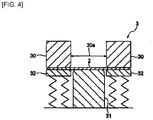
- FIG. 4 is an explanatory view illustrating a mold 3 used in the drawing-out process shown in FIG. 3
- FIG. 5 is an explanatory view illustrating the drawing-out process performed with the mold 3 shown in FIG. 4
- the mold 3 used in the drawing-out process includes a die 30; a punch 31; and a cushion pad 32.
- the die 30 is provided with a pushing hole 30a into which the base metal sheet 2 is pushed together with the punch 31.
- the cushion pad 32 is disposed at an outer peripheral position of the punch 31 so as to face an outer end surface of the die 30.
- an outer edge portion of the base metal sheet 2 is not completely constrained by the die 30 and the cushion pad 32, and the outer edge portion of the base metal sheet 2 is drawn out until it escapes from the constraint applied thereto by the die 30 and the cushion pad 32.
- the entire base metal sheet 2 may be pushed together with the punch 31 into the pushing hole 30a and drawn out.
- FIG. 6 is an explanatory view illustrating the punch 31 shown in Fig. 4 , in more detail.
- a width w 311 of a rear end side 311 of the punch 31 used in the drawing-out process is wider than a width w 310 of a distal end side 310 of the punch 31.
- a width of the pushing hole 30a is substantially uniform along an insertion direction in which the punch 31 is inserted into the pushing hole 30a.
- an inner wall of the die 30 extends substantially parallel to the insertion direction of the punch 31.
- a clearance C 30-31 between the die 30 and the punch 31 in a state where the punch 31 has been pushed into the pushing hole 30a is narrower on the rear end side 311 of the punch 31 than on the distal end side 310 of the punch 31.
- the clearance C 30-31 on the rear end side 311 of the punch 31 is set to be narrower than the sheet thickness of the base metal sheet 2 before the drawing-out process is performed. This allows the base metal sheet 2 to be pushed together with the punch 31 into the pushing hole 30a in the drawing-out process, so that the ironing process is performed on the outer edge portion of the base metal sheet 2, that is, on a region corresponding to the flange 11.
- the ironing process reduces the sheet thickness of the region corresponding to the flange 11 (decreases the thickness).
- a width variation portion 31a comprised of an inclined surface that continuously changes a width of the punch 31.
- the width variation portion 31a is disposed so as to be in contact with a region of the base metal sheet 2 corresponding to the lower side shoulder portion Rd (see FIG. 2 ) between the width variation portion 31a and the inner wall of the die 30 when the base metal sheet 2 is pushed together with the punch 31 into the pushing hole 30a in the drawing-out process.
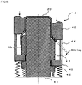
- FIG. 7 is an explanatory view illustrating a mold 4 used in the first drawing process in FIG. 3
- FIG. 8 is an explanatory drawing showing the first drawing by means of the mold 4 in FIG. 7 .
- FIGS. 7 and 8 With reference to FIGS. 7 and 8 , the movement of the mold and the state of processing during the first drawing process will be described in detail.
- the mold 4 used in the first drawing process includes a die 40; a punch 41; a drawing sleeve 42; a lifter plate 43; a killer pin 44; and a stopper 45.
- the die 40 is provided with a pushing hole 40a into which a first intermediate body 20 formed by the above drawing-out process is pushed together with the punch 41.
- the drawing sleeve 42 is disposed at an outer peripheral position of the punch 41 so as to face an outer end surface 40b of the die 40.
- FIG. 7 shows a state where the first intermediate body 20 is placed on an upper surface of the lifter plate 43 and an inner peripheral surface of the first intermediate body 20 is in contact with an outer peripheral surface 42a of the drawing sleeve 42.
- the outer end surface 40b of the die 40 is not in contact with the first intermediate body 20, so that the drawing process of the first intermediate body 20 is not started yet.
- the tip of the killer pin 44 provided on the outer end surface 40b of the die 40 does not reach the upper surface of the lifter plate 43.
- the right half of FIG. 7 shows a state where the die 40 has further descended to be in contact with the first intermediate body 20, and the drawing process has been started. At this time, the tip of the killer pin 44 reaches the upper surface of the lifter plate 43, so that the die 40 descends and the killer pin 44 pushes down the lifter plate 43. This allows maintenance of the state where the lower end of the body of the first intermediate body 20 is not in contact with the upper surface of the lifter plate 43. That is, the killer pin 44 is longer than the height of the circumferential wall of the first intermediate body 20.
- FIG. 8 shows a state where the die 40 continues to further descend and the first intermediate body 20 is pushed into the pushing hole 40a of the die 40, that is, a state where the drawing process is carried out on the body of the first intermediate body 20. Also at this time, the tip of the killer pin 44 reaches the upper surface of the lifter plate 43, and the killer pin 44 pushes down the lifter plate 43 as the die 40 descends. Therefore, when undergoing the drawing process, the lower end of the body of the first intermediate body 20 is not in contact with the upper surface of the lifter plate 43 and is in an uplifting state.
- any compressive stress in the upward direction is not applied to the circumferential wall of the body. Further, a space between the die 40 and the drawing sleeve 42 is open, and the lower portion of the body of the first intermediate body 20 (a region corresponding to the flange 11 in FIG. 2 ) is not sandwiched by the die 40 and the drawing sleeve 42.
- the inner side of the lower portion of the body of the first intermediate body 20 is in contact with the outer peripheral surface 42a of the drawing sleeve 42.
- the radius of the lower end of the body of the first intermediate body 20 does not change even if the drawing process progresses to the body of the first intermediate body 20.
- the lower end of the body of the first intermediate body 20 is not sandwiched by the die 40 and the drawing sleeve 42 as described above, it is possible to suppress a decrease in the sheet thickness of the circumferential wall of the body.
- FIG. 8 shows a state where the die 40 further continue to descent, so that the lower surface of the lifter plate 43 is brought into contact with the stopper 45 provided on the outer peripheral surface 42a of the drawing sleeve 42.
- the lower surface of the lifter plate 43 is brought into contact with the stopper 45, whereby the drawing sleeve 42 will descend in synchronization with the die 40. This leads to a constant mold gap between the die 40 and the drawing sleeve 42.
- the lower portion of the body of the first intermediate body 20 is located above the outer peripheral surface 42a of the drawing sleeve 42. Therefore, as the drawing process of the body of the first intermediate body 20 progresses, the radius of the lower end of the body of the first intermediate body 20 gradually decreases, and the sheet thickness of the lower portion of the body begins to gradually increase.
- the mold gap between the die 40 and the drawing sleeve 42 after the lower surface of the lifter plate 43 is brought into contact with the stopper 45 is set to be narrower than the sheet thickness of the lower portion of the body of the first intermediate body 20, which thickness has been increased with the progress of the drawing process.
- the mold gap between the die 40 and the drawing sleeve 42 during the ironing process is preferably 1.0 times or more and 1.35 times or less an average sheet thickness of the lower portion of the body of the first intermediate body 20 before the first drawing process is performed.
- the second and third drawing processes shown in FIG. 3 can be carried out using a conventional mold (not shown).
- the drawing process is further performed on a region of a second intermediate body 21 (see FIG. 3 ) formed in the first drawing process, the region corresponding to the body 10.
- the third drawing process corresponds to a re-striking process, in which the ironing process is performed on a region of a third intermediate body 22 (see FIG. 3 ) formed in the second drawing process, the region corresponding to the body 10.
- shrinkage occurs in the region corresponding to the flange 11 in FIG. 2 , and an increase in the thickness occurs in this region.
- the sheet thickness t 11 of the flange 11 can be decreased as compared with the sheet thickness t 101 of the circumferential wall 101 of the body 10, in the final molded material 1.
- An amount of reducing the sheet thickness of the region corresponding to the flange 11 in the drawing-out process can be adjusted, as needed, by changing the clearance C 30-31 on the rear end side 311 of the punch 31 of the mold 3 used in the drawing-out process.
- the present inventors prepared a round sheet having a thickness of 1.8 mm and a diameter of 116 mm and formed by conducting Zn-AI-Mg alloy plating on a common cold-rolled steel sheet, as the base metal sheet 2.
- the drawing-out process was then carried out under the following processing conditions.
- the Zn-AI-Mg alloy plating was applied onto both surface of the cold-rolled steel sheet, and a plating coverage was 90 g/m 2 for each surface.
- the processing could be performed without any problem.
- the ironing ratio was greater than 30% and equal to or less than 50% (when the diameter of the rear end side 311 of the punch 31 was greater than 67.5 mm and equal to or less than 68.2 mm)
- a slight scratching mark was found at a portion sliding against the die 30.
- the ironing ratio exceeded 50% (when the diameter of the rear end side 311 of the punch 31 was greater than 68.2 mm)
- seizure and cracking occurred against the inner wall of the die 30.
- the ironing ratio of the region corresponding to the flange 11 in the drawing-out process is preferably equal to or less than 50%, and more preferably equal to or less than 30%.
- the scratching is not a significant problem because it can be improved by subjecting the die or punch to a ceramic coating treatment or the like.
- Ironing Ratio % Sheet thickness before ironing ⁇ Sheet thickness after ironing Sheet thickness before ironing ⁇ 100
- a value of the sheet thickness of the base metal sheet can be used as the sheet thickness before ironing.
- the processing could be performed without any problem.
- the width variation portion 31a was formed with the right angle step, that is, when the front end side 310 and the rear end side 311 of the punch 31 are formed with one step difference, plating residue was generated at a portion that was in contact with the right angle step.
- the width variation portion 31a When the width variation portion 31a was provided so as to be in contact with the region corresponding to the lower side shoulder portion Rd, the ironing process of the region corresponding to the flange 11 could be satisfactorily performed. However, when the width variation portion 31a was provided so as to be in contact with the region corresponding to the flange 11, the thickness of a part of the flange portion 11 could not be sufficiently decreased. Further, when the width variation portion 31a was provided so as to be in contact with the region corresponding to the body 10, a part of the body 10 became thinner than the target sheet thickness.
- the position of the width variation portion 31a is determined by performing the molding to the molded material which has completed the redrawing process in advance after determining mold conditions for mass production, and then counting backward from the position corresponding to the lower side shoulder portion Rd.
- the lower end of the body of the first intermediate body is referred to as a flange.
- Table 1 shows a relationship between an average sheet thickness of the flange before the drawing process and a diameter of the flange before and after the drawing process, on the generation of wrinkles and/or buckling when the drawing sleeve is not used.
- the symbol t 0 is a sheet thickness of the base metal plate
- the symbol t 1 is an average sheet thickness of the flange before the drawing process, that is, an average sheet thickness of the region corresponding to the flange after the drawing-out process.
- the symbol D (n-1) is a diameter of the flange after the n-1 th drawing process
- the symbol D n is a diameter of the flange after the n th drawing process.
- the wrinkles and/or buckling were generated under conditions of t 1 ⁇ t 0 and D n ⁇ 0.93 ⁇ D (n-1) , that is, conditions where the average sheet thickness t 1 of the flange before the drawing process is thinner than the sheet thickness t 0 of the base metal sheet (t 1 ⁇ t 0 ) and the diameter of the flange D n after the n th drawing process is significantly smaller than the diameter of the flange D( n-1 ) after the n-1 th drawing process (D n ⁇ 0.93 ⁇ D (n-1) ).
- the mold gap was made constant at the timing when contraction processing began. Further, it was carried out under the condition where the diameter of the flange after the n th drawing process was significantly smaller than the diameter of the flange after the (n-1) th drawing process (D n ⁇ 0.93 ⁇ D (n-1) ).
- the mold gap (clearance) was set to various values under the above condition that the flange diameter D n after the n th drawing process was significantly smaller than the flange diameter D( n-1 ) after the n-1 th drawing process, and the drawing process was carried out. As shown in Table 2, no winkle or buckling was generated when the mold gap (clearance) was 1.0 times or more and 1.35 times or less the average sheet thickness of the flange before the drawing process.
- FIG. 9 is a graph showing the sheet thickness distribution of the molded material produced from the first intermediate body.
- FIG. 10 is an explanatory view showing the sheet thickness measured positions in FIG. 9 .
- the implementation of the drawing-out process involving the ironing process prior to the drawing process could allow the thinner sheet thickness of the flange 11 in the final molded material than the sheet thickness of the base metal sheet (1.8 mm) and the sheet thickness of the circumferential wall of the body (about 1.6 mm). Further, assuming that outer dimensions of both molded materials are the same, the molded material subjected to the drawing-out process involving the ironing process prior to the drawing process (the present invention) had a weight lighter than the molded material subjected to the conventional common drawing method by 10%.
- the region corresponding to the flange 11 of the base metal sheet 2 is stretched.
- a smaller base metal sheet may be used taking into consideration, in advance, an amount of stretching the region corresponding to the flange 11, or an unnecessary portion of the flange 11 may be trimmed.
- the drawing-out process involves an ironing process performed on the region corresponding to the flange 11 of the base metal sheet 2 by pushing the base metal sheet 2 together with the punch 31 into the pushing hole 30a, and the subsequent drawing process molds the portion where the sheet thickness has been decreased by the ironing process, while being sandwiched by the die 40 and the drawing sleeve. Therefore, the wrinkles and buckling can be prevented, the sheet thickness of the flange can be prevented from becoming unnecessarily thicker, and the weight of the molded material can be reduced.
- This configuration is particularly useful for applications in which weight reduction of the molded material and size reduction of the base metal sheet are required, such as motor cases.
- the ironing ratio of the ironing process performed during the drawing-out process is equal to or less than 50%, and therefore the generation of seizure and cracking can be avoided.
- the width variation portion 31a comprised of the inclined surface that continuously changes the width of the punch 31 is provided between the distal end side 310 and the rear end side 311, so that it is possible to avoid the generation of plating residue due to the contact with the width variation portion 31a in the ironing process.
- the width variation portion 31a is disposed so as to be in contact with the region corresponding to the lower side shoulder portion Rd formed between the circumferential wall 101 of the body 10 and the flange 11, so that the thickness of the flange 11 can be sufficiently decreased and the target sheet thickness of the body 10 can be more reliably achieved.
- the present embodiment illustrates that the three drawing processes are performed, the number of the drawing processes may be changed, as needed, according to the size and required dimensional accuracy of the molded material.
Abstract
Description
- This invention relates to a method for producing a molded material including a tubular body and a flange formed at an end portion of the body, and also relates to a molded material.
- As disclosed, for example, in
non-patent document 1, a molded material including a tubular body and a flange formed at an end portion of the body is produced by performing a drawing process. The drawing process forms the body by drawing a base metal sheet, so that the thickness of the body is lower than that of the base sheet. On the other hand, a region of the metal sheet corresponding to the flange shrinks as a whole in response to the formation of the body, so that the thickness of the flange is higher than that of the base sheet. Hereinafter, the base material may be referred to as a "blank". - The molded material as described above may be used as a motor case disclosed, for example, in
patent document 1 as described below. In this case, the body is expected to function as a shielding material for preventing magnetic leakage to the outside of the motor case. Depending on motor structures, the body is also expected to function as a back yoke of a stator. The performance of the body as the shield material or back yoke is improved as the thickness of the body increases. Therefore, when a molded material is produced by drawing, as described above, a base metal sheet with a thickness larger than the required thickness of the body is selected taking into account the reduction in thickness of the body caused by the drawing process. Meanwhile, the flange is often used for mounting the motor case on a mounting object. Therefore, the flange is expected to have a certain strength. - Patent Document 1: Japanese Patent Application Publication No.
2013-51765 A - Non-patent Document 1: Masao Murakawa, et.al., "Basics of Plastic Processing", First Edition, SANGYO-TOSHO Publishing Co. Ltd., January 16, 1990, pp. 104 to 107
- However, the conventional method for producing the molded material as described above produces the molded material including the tubular body and the flange formed at the end portion of the body by the drawing process, so that the thickness of the flange is larger than that of the base sheet. For this reason, the flange may become unnecessarily thicker over a thickness required for obtaining the expected performance of the flange. This means that the molded material becomes unnecessarily heavy, which cannot be ignored in applications in which weight reduction is required, such as motor cases.
- On the other hand, in a multi-stage drawing process, when a change in diameter reduction of the flange before and after the drawing process is large, in other words, when a diameter of the flange after the drawing process becomes significantly smaller than the diameter of the flange before the drawing process, the lower thickness of the flange after the drawing process may generate wrinkles and/or buckling in the flange. The wrinkles and/or buckling may cause cracks during the subsequent drawing process.
- In such a case, a drawing process using a drawing sleeve may be carried out in order to prevent the wrinkles and/or buckling. However, the drawing process is carried out by sandwiching the flange between a die and the drawing sleeve, so that a tensile stress will act on the body, causing a decrease in thickness of a circumferential wall of the body.
- The present invention has been made to solve the above problems. An object of the present invention is to provide a method for producing a molded material and the molded material, which can avoid unnecessary thickening of the flange, reduce a weight of the molded material and achieve size reduction of the base metal sheet.
- The present invention relates to a method for producing a molded material, the molded material comprising a tubular body and a flange formed at an end portion of the body, the molded material being produced by performing at least two molding processes on a base metal sheet, wherein the at least two molding processes comprise at least one drawing-out process and at least one drawing process performed after the drawing-out process; wherein the drawing-out process is carried out using a mold that comprises a punch and a die having a pushing hole; wherein a width of the punch on a rear end side is wider than a width of the punch on a distal end side so that when the punch is pushed into the pushing hole of the die, a clearance between the die and the punch is narrower on the rear end side than on the distal end side; and wherein an ironing process is performed on a region corresponding to the flange of the base metal sheet by pushing the base metal sheet together with the punch into the pushing hole in the drawing-out process.
- In the method for producing the molded material, the drawing process is carried out using a mold comprising a die and a drawing sleeve, and in the drawing process, an ironing process is performed on a region corresponding to the flange of the base material sheet subjected to the ironing process in the drawing-out process, while maintaining a constant mold gap between the die and the drawing sleeve.
- Further, the drawing process performed at the constant mold gap between the die and the drawing sleeve is preferably carried out such that the mold gap is 1.0 times or more and 1.35 times or less an average thickness of the flange before the drawing process. Alternatively, the drawing process is carried out using a mold comprising a die, a drawing sleeve and a punch, and the drawing process that does not reduce a diameter of the flange is preferably carried out while opening the mold gap between the die and the drawing sleeve, and the drawing process that reduces a diameter of the flange is preferably carried out such that the mold gap between the die and the drawing sleeve is 1.0 times or more and 1.35 times or less an average thickness of the flange before the drawing process.
- Further, the present invention relates to a molded material which comprises a tubular body and a flange formed at an end portion of the body, and is produced by carrying out at least two molding processes on a base metal sheet, wherein the at least two molding processes comprise at least one drawing-out process and at least one drawing process performed after the drawing-out process; wherein in the drawing-out process, an ironing process is performed on a region corresponding to the flange of the base metal sheet; and wherein in the drawing process, an ironing process is also performed on only a region corresponding to the flange, whereby the thickness of the flange is lower than that of a circumferential wall of the body.
- Furthermore, the present invention relates to a molded material which comprises a tubular body and a flange formed at an end portion of the body and is produced by carrying out at least two molding processes on a base metal sheet, wherein the at least two molding processes comprise at least one drawing-out process and at least one drawing process performed after the drawing-out process; wherein in the drawing-out process, an ironing process is performed on a region corresponding to the flange of the base metal sheet; and wherein in the drawing process, an ironing process is also performed on only a region corresponding to the flange, whereby the thickness of the flange is lower than that of the base metal sheet.
- According to the method for producing the molded material and the molded material according to the present invention, the drawing-out process involves the ironing process performed on the region corresponding to the flange of the base metal sheet by pushing the base metal sheet together with the punch into the pushing hole, and during the drawing process, only the region corresponding to the flange of the base metal sheet subjected to the ironing process in the drawing-out process is subjected to the ironing process and molded while sandwiching the region between the die and the drawing sleeve. Therefore, generation of wrinkles and buckling in the flange can be prevented, and breakage can be avoided. Further, an unnecessary increase in the thickness of the flange can be avoided so that the weight of the molded material can be reduced. This configuration is particularly useful for various applications in which weight reduction is required, such as motor cases.
-
-
FIG. 1 is a perspective view showing a molded material produced by a method for producing a molded material according toEmbodiment 1 of the present invention. -
FIG. 2 is a sectional view taken along the line II-II inFIG. 1 . -
FIG. 3 is an explanatory view illustrating a method for producing the molded material shown inFIG. 1 . -
FIG. 4 is an explanatory view illustrating a mold used in the drawing-out process shown inFIG. 3 . -
FIG. 5 is an explanatory view illustrating the drawing-out process performed with the mold shown inFIG. 4 . -
FIG. 6 is an explanatory view illustrating the punch shown inFIG. 4 , in more detail. -
FIG. 7 is an explanatory view illustrating the mold used in a first drawing process show inFIG. 3 . -
FIG. 8 is an explanatory view illustrating a first drawing process performed with the mold shown inFig. 7 . -
FIG. 9 is a graph showing a thickness distribution of a molded material produced by a method for producing a molded material according to the present embodiment. -
FIG. 10 is an explanatory view showing the sheet thickness measured positions inFIG. 9 . - Embodiments of the present invention will be described below with reference to the drawings.
-
FIG. 1 is a perspective view showing a moldedmaterial 1 produced by a method for producing a mold material according toEmbodiment 1 of the present invention. As shown inFIG. 1 , the moldedmaterial 1 produced by the method for producing the molded material according to the present embodiment includes a body 10 and aflange 11. The body 10 is a tubular portion having atop wall 100 and acircumferential wall 101 that extends from an outer edge of thetop wall 100. Depending on the orientation of the moldedmaterial 1 to be used, thetop wall 100 may be referred to by other terms, such as a bottom wall. InFIG. 1 , the body 10 is shown to have a perfectly circular sectional shape, but the body 10 may have another shape, for example, such as an elliptical sectional shape or angular tubular shape. Thetop wall 100 may be subjected to further processing. For example, a protrusion further projecting from thetop wall 100 can be formed. Theflange 11 is a sheet portion formed on an end portion (an end of the circumferential wall 101) of the body 10. -
FIG. 2 is a sectional view taken along the line II-II inFig. 1 . As shown inFIG. 2 , a sheet thickness t11 of theflange 11 is lower than a sheet thickness t101 of thecircumferential wall 101 of the body 10. The reason for this is that the ironing process is performed on a region of corresponding to theflange 11 of a base metal sheet 2 (seeFig. 3 ), as will be described in detail below. As used herein, the sheet thickness t11 of theflange 11 means an average value of the sheet thickness of theflange 11 from a lower end of a lower side shoulder portion Rd between thecircumferential wall 101 and theflange 11 to an outer end of theflange 11. Similarly, the sheet thickness t101 of thecircumferential wall 101 means an average value of the sheet thickness of thecircumferential wall 101 from an upper end of the lower side shoulder portion Rd to a lower end of an upper side shoulder portion Rp. -
FIG. 3 is an explanatory view illustrating the method for producing the moldedmaterial 1 shown inFIG. 1 . The method for producing the molded material according to the present invention produces the moldedmaterial 1 by performing at least two molding processes on a flatbase metal sheet 2. The at least two molding processes include at least one drawing-out process and at least one drawing process performed after the drawing-out process. In the method for producing the molded material according to this embodiment, the moldedmaterial 1 is produced by one drawing-out process and four redrawing processes (first to fourth drawing processes). -
FIG. 4 is an explanatory view illustrating amold 3 used in the drawing-out process shown inFIG. 3 , andFIG. 5 is an explanatory view illustrating the drawing-out process performed with themold 3 shown inFIG. 4 . As shown inFIG. 4 , themold 3 used in the drawing-out process includes a die 30; apunch 31; and acushion pad 32. Thedie 30 is provided with a pushinghole 30a into which thebase metal sheet 2 is pushed together with thepunch 31. Thecushion pad 32 is disposed at an outer peripheral position of thepunch 31 so as to face an outer end surface of thedie 30. As shown inFIG. 5 , in the drawing-out process, an outer edge portion of thebase metal sheet 2 is not completely constrained by thedie 30 and thecushion pad 32, and the outer edge portion of thebase metal sheet 2 is drawn out until it escapes from the constraint applied thereto by thedie 30 and thecushion pad 32. The entirebase metal sheet 2 may be pushed together with thepunch 31 into the pushinghole 30a and drawn out. -
FIG. 6 is an explanatory view illustrating thepunch 31 shown inFig. 4 , in more detail. As shown inFIG. 6 , a width w311 of arear end side 311 of thepunch 31 used in the drawing-out process is wider than a width w310 of adistal end side 310 of thepunch 31. Meanwhile a width of the pushinghole 30a is substantially uniform along an insertion direction in which thepunch 31 is inserted into the pushinghole 30a. In other words, an inner wall of the die 30 extends substantially parallel to the insertion direction of thepunch 31. - Thus, as shown in
FIG. 6 , a clearance C30-31 between the die 30 and thepunch 31 in a state where thepunch 31 has been pushed into the pushinghole 30a is narrower on therear end side 311 of thepunch 31 than on thedistal end side 310 of thepunch 31. The clearance C30-31 on therear end side 311 of thepunch 31 is set to be narrower than the sheet thickness of thebase metal sheet 2 before the drawing-out process is performed. This allows thebase metal sheet 2 to be pushed together with thepunch 31 into the pushinghole 30a in the drawing-out process, so that the ironing process is performed on the outer edge portion of thebase metal sheet 2, that is, on a region corresponding to theflange 11. The ironing process reduces the sheet thickness of the region corresponding to the flange 11 (decreases the thickness). - It should be noted that between the
distal end side 310 and therear end side 311 of thepunch 31 is provided awidth variation portion 31a comprised of an inclined surface that continuously changes a width of thepunch 31. Thewidth variation portion 31a is disposed so as to be in contact with a region of thebase metal sheet 2 corresponding to the lower side shoulder portion Rd (seeFIG. 2 ) between thewidth variation portion 31a and the inner wall of the die 30 when thebase metal sheet 2 is pushed together with thepunch 31 into the pushinghole 30a in the drawing-out process. - Next,
FIG. 7 is an explanatory view illustrating amold 4 used in the first drawing process inFIG. 3 , andFIG. 8 is an explanatory drawing showing the first drawing by means of themold 4 inFIG. 7 . With reference toFIGS. 7 and8 , the movement of the mold and the state of processing during the first drawing process will be described in detail. - As shown in
FIG. 7 , themold 4 used in the first drawing process includes a die 40; apunch 41; adrawing sleeve 42; alifter plate 43; a killer pin 44; and a stopper 45. Thedie 40 is provided with a pushing hole 40a into which a firstintermediate body 20 formed by the above drawing-out process is pushed together with thepunch 41. The drawingsleeve 42 is disposed at an outer peripheral position of thepunch 41 so as to face anouter end surface 40b of thedie 40. - The left half of
FIG. 7 shows a state where the firstintermediate body 20 is placed on an upper surface of thelifter plate 43 and an inner peripheral surface of the firstintermediate body 20 is in contact with an outerperipheral surface 42a of the drawingsleeve 42. At this time, although thedie 40 begins to descend, theouter end surface 40b of the die 40 is not in contact with the firstintermediate body 20, so that the drawing process of the firstintermediate body 20 is not started yet. The tip of the killer pin 44 provided on theouter end surface 40b of the die 40 does not reach the upper surface of thelifter plate 43. - The right half of
FIG. 7 shows a state where thedie 40 has further descended to be in contact with the firstintermediate body 20, and the drawing process has been started. At this time, the tip of the killer pin 44 reaches the upper surface of thelifter plate 43, so that thedie 40 descends and the killer pin 44 pushes down thelifter plate 43. This allows maintenance of the state where the lower end of the body of the firstintermediate body 20 is not in contact with the upper surface of thelifter plate 43. That is, the killer pin 44 is longer than the height of the circumferential wall of the firstintermediate body 20. - Next, the left half of
FIG. 8 shows a state where thedie 40 continues to further descend and the firstintermediate body 20 is pushed into the pushing hole 40a of the die 40, that is, a state where the drawing process is carried out on the body of the firstintermediate body 20. Also at this time, the tip of the killer pin 44 reaches the upper surface of thelifter plate 43, and the killer pin 44 pushes down thelifter plate 43 as thedie 40 descends. Therefore, when undergoing the drawing process, the lower end of the body of the firstintermediate body 20 is not in contact with the upper surface of thelifter plate 43 and is in an uplifting state. Since the lower end of the body is uplifting from the upper surface of thelifter plate 43, any compressive stress in the upward direction is not applied to the circumferential wall of the body.
Further, a space between the die 40 and the drawingsleeve 42 is open, and the lower portion of the body of the first intermediate body 20 (a region corresponding to theflange 11 inFIG. 2 ) is not sandwiched by thedie 40 and the drawingsleeve 42. - In the state shown in the left half of
FIG. 8 , the inner side of the lower portion of the body of the firstintermediate body 20 is in contact with the outerperipheral surface 42a of the drawingsleeve 42. In such a state, the radius of the lower end of the body of the firstintermediate body 20 does not change even if the drawing process progresses to the body of the firstintermediate body 20. In this case, since the lower end of the body of the firstintermediate body 20 is not sandwiched by thedie 40 and the drawingsleeve 42 as described above, it is possible to suppress a decrease in the sheet thickness of the circumferential wall of the body. - The right half of
FIG. 8 shows a state where the die 40 further continue to descent, so that the lower surface of thelifter plate 43 is brought into contact with the stopper 45 provided on the outerperipheral surface 42a of the drawingsleeve 42. The lower surface of thelifter plate 43 is brought into contact with the stopper 45, whereby the drawingsleeve 42 will descend in synchronization with thedie 40. This leads to a constant mold gap between the die 40 and the drawingsleeve 42. - In the state shown in the right half of
FIG. 8 , the lower portion of the body of the firstintermediate body 20 is located above the outerperipheral surface 42a of the drawingsleeve 42. Therefore, as the drawing process of the body of the firstintermediate body 20 progresses, the radius of the lower end of the body of the firstintermediate body 20 gradually decreases, and the sheet thickness of the lower portion of the body begins to gradually increase. The mold gap between the die 40 and the drawingsleeve 42 after the lower surface of thelifter plate 43 is brought into contact with the stopper 45 is set to be narrower than the sheet thickness of the lower portion of the body of the firstintermediate body 20, which thickness has been increased with the progress of the drawing process. By setting the mold gap in such a way, an ironing process can be performed on the lower portion of the body of the firstintermediate body 20. The ironing process can decrease an amount of reducing the radius of the lower end of the body of the firstintermediate body 20. Further, the ironing process can allow prevention of wrinkles and buckling. As will be described below, the mold gap between the die 40 and the drawingsleeve 42 during the ironing process is preferably 1.0 times or more and 1.35 times or less an average sheet thickness of the lower portion of the body of the firstintermediate body 20 before the first drawing process is performed. - The second and third drawing processes shown in
FIG. 3 can be carried out using a conventional mold (not shown). In the second drawing process, the drawing process is further performed on a region of a second intermediate body 21 (seeFIG. 3 ) formed in the first drawing process, the region corresponding to the body 10. The third drawing process corresponds to a re-striking process, in which the ironing process is performed on a region of a third intermediate body 22 (seeFIG. 3 ) formed in the second drawing process, the region corresponding to the body 10. - In the first to third drawing processes, shrinkage occurs in the region corresponding to the
flange 11 inFIG. 2 , and an increase in the thickness occurs in this region. However, by sufficiently reducing the sheet thickness of the region corresponding to theflange 11 in the drawing-out process, the sheet thickness t11 of theflange 11 can be decreased as compared with the sheet thickness t101 of thecircumferential wall 101 of the body 10, in the final moldedmaterial 1. An amount of reducing the sheet thickness of the region corresponding to theflange 11 in the drawing-out process can be adjusted, as needed, by changing the clearance C30-31 on therear end side 311 of thepunch 31 of themold 3 used in the drawing-out process. - Next, Examples will be described. The present inventors prepared a round sheet having a thickness of 1.8 mm and a diameter of 116 mm and formed by conducting Zn-AI-Mg alloy plating on a common cold-rolled steel sheet, as the
base metal sheet 2. The drawing-out process was then carried out under the following processing conditions. Here, the Zn-AI-Mg alloy plating was applied onto both surface of the cold-rolled steel sheet, and a plating coverage was 90 g/m2 for each surface. - Ironing ratio of region corresponding to flange 11: -20% to 60%;
- Curvature radius Rd of mold 3: 6 mm;
- Diameter of pushing
hole 30a: 70 mm; - Diameter of
distal end side 310 of punch 31: 65.7 mm; - Diameter of
rear end side 311 of punch 31: 65.7 mm to 68.6 mm; - Shape of
width variation portion 31a: inclined surface or right angle step; - Position of
width variation portion 31a: region corresponding to lower side shoulder portion Rd, region corresponding to flange 11 or region corresponding to body 10; - Press oil: TN-20; and
- Material of die and punch: SKD 11 (HRC hardness: 60).
- When the ironing ratio was 30% or less (when the diameter of the
rear end side 311 of thepunch 31 was 67.5 mm or less), the processing could be performed without any problem. However, when the ironing ratio was greater than 30% and equal to or less than 50% (when the diameter of therear end side 311 of thepunch 31 was greater than 67.5 mm and equal to or less than 68.2 mm), a slight scratching mark was found at a portion sliding against thedie 30. Further, when the ironing ratio exceeded 50% (when the diameter of therear end side 311 of thepunch 31 was greater than 68.2 mm), seizure and cracking occurred against the inner wall of thedie 30. Therefore, these results demonstrate that the ironing ratio of the region corresponding to theflange 11 in the drawing-out process is preferably equal to or less than 50%, and more preferably equal to or less than 30%. However, the scratching is not a significant problem because it can be improved by subjecting the die or punch to a ceramic coating treatment or the like. - The ironing ratio is as represented by the following equation:

- Here, a value of the sheet thickness of the base metal sheet can be used as the sheet thickness before ironing.
- As shown in
FIG. 6 , when thewidth variation portion 31a was formed with the inclined surface, the processing could be performed without any problem. However, when thewidth variation portion 31a was formed with the right angle step, that is, when thefront end side 310 and therear end side 311 of thepunch 31 are formed with one step difference, plating residue was generated at a portion that was in contact with the right angle step. These results demonstrate that it is preferable to form thewidth variation portion 31a with the inclined surface. - When the
width variation portion 31a was provided so as to be in contact with the region corresponding to the lower side shoulder portion Rd, the ironing process of the region corresponding to theflange 11 could be satisfactorily performed. However, when thewidth variation portion 31a was provided so as to be in contact with the region corresponding to theflange 11, the thickness of a part of theflange portion 11 could not be sufficiently decreased. Further, when thewidth variation portion 31a was provided so as to be in contact with the region corresponding to the body 10, a part of the body 10 became thinner than the target sheet thickness. These results demonstrate that it is preferable to provide thewidth variation portion 31a so as to be in contact with the region corresponding to the lower side shoulder portion Rd. - It should be noted that the position of the
width variation portion 31a is determined by performing the molding to the molded material which has completed the redrawing process in advance after determining mold conditions for mass production, and then counting backward from the position corresponding to the lower side shoulder portion Rd. - In Examples, hereinafter, the lower end of the body of the first intermediate body is referred to as a flange.
- Table 1 shows a relationship between an average sheet thickness of the flange before the drawing process and a diameter of the flange before and after the drawing process, on the generation of wrinkles and/or buckling when the drawing sleeve is not used. The symbol t0 is a sheet thickness of the base metal plate, and the symbol t1 is an average sheet thickness of the flange before the drawing process, that is, an average sheet thickness of the region corresponding to the flange after the drawing-out process. The symbol D(n-1) is a diameter of the flange after the n-1th drawing process, and the symbol Dn is a diameter of the flange after the nth drawing process. The wrinkles and/or buckling were generated under conditions of t1 < t0 and Dn < 0.93 × D(n-1), that is, conditions where the average sheet thickness t1 of the flange before the drawing process is thinner than the sheet thickness t0 of the base metal sheet (t1 < t0) and the diameter of the flange Dn after the nth drawing process is significantly smaller than the diameter of the flange D(n-1) after the n-1th drawing process (Dn < 0.93 × D(n-1)).
[Table 1] t1 > t0 t1 = t0 t1 < t0 Dn>D(n-1) Good Good Good Dn = 0.98 × D(n-1) Good Good Slight Wrinkles Dn < 0.93 × D(n-1) Good Good Wrinkles and Buckling Sheet Thickness of Base Material: t0, Sheet Thickness of Flange before Drawing Process: t1
Diameter of Flange after n-1th Drawing Process: Dn-1
Diameter of Flange after nth drawing process: Dn - The results in the case of using the drawing sleeve are shown in Table 2. In this case, the diameter of the flange is not changed when performing the drawing process on the body. Therefore, in this case, a space between the die 40 and the drawing
sleeve 42 was opened such that the outer edge portion was not sandwiched, thereby suppressing a decrease in the sheet thickness of the circumferential wall of the body. Further, when the ironing process is performed on the region where the sheet thickness has been decreased by carrying out the ironing process in the step of the drawing-out process, the diameter of the flange is reduced. In this case, the mold gap (clearance) between the die 40 and the drawingsleeve 42 was set to be constant at various values.[Table 2] Mold Gap (Clearance) Evaluation Flange Average Sheet Thickness × 1.5 Wrinkles and Buckling Flange Average Sheet Thickness × 1.35 good Flange Average Sheet Thickness × 1.2 good Flange Average Sheet Thickness × 1.0 good - Here, for the region where the ironing process was performed to decrease the sheet thickness, the mold gap was made constant at the timing when contraction processing began.
Further, it was carried out under the condition where the diameter of the flange after the nth drawing process was significantly smaller than the diameter of the flange after the (n-1)th drawing process (Dn <0.93 × D(n-1)). - The mold gap (clearance) was set to various values under the above condition that the flange diameter Dn after the nth drawing process was significantly smaller than the flange diameter D(n-1) after the n-1th drawing process, and the drawing process was carried out. As shown in Table 2, no winkle or buckling was generated when the mold gap (clearance) was 1.0 times or more and 1.35 times or less the average sheet thickness of the flange before the drawing process.
- Next,
FIG. 9 is a graph showing the sheet thickness distribution of the molded material produced from the first intermediate body.FIG. 10 is an explanatory view showing the sheet thickness measured positions inFIG. 9 . - The implementation of the drawing-out process involving the ironing process prior to the drawing process could allow the thinner sheet thickness of the
flange 11 in the final molded material than the sheet thickness of the base metal sheet (1.8 mm) and the sheet thickness of the circumferential wall of the body (about 1.6 mm). Further, assuming that outer dimensions of both molded materials are the same, the molded material subjected to the drawing-out process involving the ironing process prior to the drawing process (the present invention) had a weight lighter than the molded material subjected to the conventional common drawing method by 10%. - When the drawing-out process involving the ironing is carried out, the region corresponding to the
flange 11 of thebase metal sheet 2 is stretched. In order to form the molded material subjected to the drawing-out process involving the ironing (the present invention) and the molded material subjected to the conventional common drawing method, both of which have the same dimensions, either a smaller base metal sheet may be used taking into consideration, in advance, an amount of stretching the region corresponding to theflange 11, or an unnecessary portion of theflange 11 may be trimmed. - In such a method for producing the molded material and the molded material produced thereby, the drawing-out process involves an ironing process performed on the region corresponding to the
flange 11 of thebase metal sheet 2 by pushing thebase metal sheet 2 together with thepunch 31 into the pushinghole 30a, and the subsequent drawing process molds the portion where the sheet thickness has been decreased by the ironing process, while being sandwiched by thedie 40 and the drawing sleeve. Therefore, the wrinkles and buckling can be prevented, the sheet thickness of the flange can be prevented from becoming unnecessarily thicker, and the weight of the molded material can be reduced. This configuration is particularly useful for applications in which weight reduction of the molded material and size reduction of the base metal sheet are required, such as motor cases. - Further, the ironing ratio of the ironing process performed during the drawing-out process is equal to or less than 50%, and therefore the generation of seizure and cracking can be avoided.
- Furthermore, the
width variation portion 31a comprised of the inclined surface that continuously changes the width of thepunch 31 is provided between thedistal end side 310 and therear end side 311, so that it is possible to avoid the generation of plating residue due to the contact with thewidth variation portion 31a in the ironing process. - Moreover, the
width variation portion 31a is disposed so as to be in contact with the region corresponding to the lower side shoulder portion Rd formed between thecircumferential wall 101 of the body 10 and theflange 11, so that the thickness of theflange 11 can be sufficiently decreased and the target sheet thickness of the body 10 can be more reliably achieved. - Further, when the drawing process is performed on the body, that is, when the flange diameter does not change, a decrease in the sheet thickness of the circumferential wall of the body is suppressed by opening the space between the die 40 and the drawing
sleeve 42 so as not to sandwich the material. On the other hand, when the drawing process is performed on the region where the sheet thickness has been decreased by the ironing process in the drawing-out process, the molding is carried out while maintaining the constant mold gap between the die 40 and the drawingsleeve 42, whereby the generation of wrinkles and buckling in the region corresponding to the flange can be avoided. - Further, although the present embodiment illustrates that the three drawing processes are performed, the number of the drawing processes may be changed, as needed, according to the size and required dimensional accuracy of the molded material.
Claims (9)
- A method for producing a molded material, the molded material comprising a tubular body and a flange formed at an end portion of the body, the molded material being produced by performing at least two molding processes on a base metal sheet,
wherein the at least two molding processes comprise at least one drawing-out process and at least one drawing process performed after the drawing-out process;
wherein the drawing-out process is carried out using a mold that comprises a punch and a die having a pushing hole;
wherein a width of the punch on a rear end side is wider than a width of the punch on a distal end side so that when the punch is pushed into the pushing hole of the die, a clearance between the die and the punch is narrower on the rear end side than on the distal end side;
wherein an ironing process is performed on only a region corresponding to the flange of the base metal sheet by pushing the base metal sheet together with the punch into the pushing hole in the drawing-out process;
wherein the drawing process is carried out using a mold comprising a die and a drawing sleeve; and
wherein in the drawing process, an ironing process is performed on a region corresponding to the flange of the base material sheet subjected to the ironing process in the drawing-out process, while maintaining a constant mold gap between the die and the drawing sleeve. - The method for producing the molded material according to claim 1, wherein an ironing ratio of the ironing process performed during the drawing-out process is equal to or less than 50%.
- The method for producing the molded material according to claim 1 or 2, wherein between the distal end side and the rear end side of the punch is provided a width variation portion comprised of an inclined surface that continuously changes a width of the punch.
- The method for producing the molded material according to any one of claims 1 to 3, wherein the width variation portion is disposed so as to be in contact with a region corresponding to a shoulder portion formed between a circumferential wall of the body and the flange.
- The method for producing the molded material according to claim 1, wherein the mold gap between the die and the drawing sleeve is 1.0 times or more and 1.35 times or less an average thickness of the region corresponding to the flange of the base metal sheet.
- The method for producing the molded material according to claim 1,
wherein the drawing process is carried out while opening the mold gap between the die and the drawing sleeve, when the drawing process is performed on the tubular body of the molded material, and
wherein the drawing process is carried out such that the mold gap between the die and the drawing sleeve is 1.0 times or more and 1.35 times or less an average thickness of the flange before the drawing process, when the drawing process is performed on the region corresponding to the flange of the molded material. - A molded material comprising: a tubular body; and a flange formed at an end portion of the body, the molded material being produced by carrying out at least two molding processes on a base metal sheet,
wherein the at least two molding processes comprise at least one drawing-out process and at least one drawing process performed after the drawing-out process;
wherein in the drawing-out process, an ironing process is performed on a region corresponding to the flange of the base metal sheet; and
wherein in the drawing process, an ironing process is also performed on only a region corresponding to the flange, whereby the thickness of the flange is lower than that of a circumferential wall of the body. - A molded material comprising: a tubular body; and a flange formed at an end portion of the body, the molded material being produced by carrying out at least two molding processes on a base metal sheet,
wherein the at least two molding processes comprise at least one drawing-out process and at least one drawing process performed after the drawing-out process;
wherein in the drawing-out process, an ironing process is performed on a region corresponding to the flange of the base metal sheet; and
wherein in the drawing process, an ironing process is also performed on only a region corresponding to the flange, whereby the thickness of the flange is lower than that of the base metal sheet. - The molded material according to claim 7 or 8, wherein the thickness of the flange of the molded material is decreased as compared with the thickness of the base metal sheet.
Priority Applications (1)
| Application Number | Priority Date | Filing Date | Title |
|---|---|---|---|
| PL17756457T PL3401033T3 (en) | 2016-02-23 | 2017-02-21 | Molded material production method and molded material |
Applications Claiming Priority (2)
| Application Number | Priority Date | Filing Date | Title |
|---|---|---|---|
| JP2016032443 | 2016-02-23 | ||
| PCT/JP2017/006292 WO2017146019A1 (en) | 2016-02-23 | 2017-02-21 | Molded material production method and molded material |
Publications (3)
| Publication Number | Publication Date |
|---|---|
| EP3401033A1 true EP3401033A1 (en) | 2018-11-14 |
| EP3401033A4 EP3401033A4 (en) | 2019-01-23 |
| EP3401033B1 EP3401033B1 (en) | 2020-04-22 |
Family
ID=59686214
Family Applications (1)
| Application Number | Title | Priority Date | Filing Date |
|---|---|---|---|
| EP17756457.2A Active EP3401033B1 (en) | 2016-02-23 | 2017-02-21 | Molded material production method and molded material |
Country Status (10)
| Country | Link |
|---|---|
| US (1) | US10500626B2 (en) |
| EP (1) | EP3401033B1 (en) |
| JP (1) | JP6305648B2 (en) |
| KR (1) | KR101935759B1 (en) |
| CN (1) | CN108778551B (en) |
| MX (1) | MX2018010129A (en) |
| MY (1) | MY170562A (en) |
| PL (1) | PL3401033T3 (en) |
| TW (1) | TWI711499B (en) |
| WO (1) | WO2017146019A1 (en) |
Cited By (1)
| Publication number | Priority date | Publication date | Assignee | Title |
|---|---|---|---|---|
| EP3401034A4 (en) * | 2016-02-24 | 2019-02-27 | Nisshin Steel Co., Ltd. | Molded material production method and molded material |
Families Citing this family (4)
| Publication number | Priority date | Publication date | Assignee | Title |
|---|---|---|---|---|
| MY170562A (en) | 2016-02-23 | 2019-08-19 | Nisshin Steel Co Ltd | Molded material production method |
| EP3750647B1 (en) * | 2019-06-14 | 2021-10-13 | Saeta GmbH & Co. KG | A method for forming a deep draw closure cap |
| CN110722045B (en) * | 2019-10-28 | 2021-04-02 | 安徽工业大学 | Deep barrel high-reduction-rate deep drawing process |
| CN112845786A (en) * | 2020-12-30 | 2021-05-28 | 大连神通模具有限公司 | New process for manufacturing plate by cold stamping and deep drawing |
Family Cites Families (17)
| Publication number | Priority date | Publication date | Assignee | Title |
|---|---|---|---|---|
| JPS57159224A (en) * | 1981-03-27 | 1982-10-01 | Mitsubishi Electric Corp | Plastic working method for metal |
| JPS635648A (en) | 1986-06-25 | 1988-01-11 | Matsushita Electric Ind Co Ltd | Line terminal equipment |
| US20080299352A1 (en) * | 2007-05-31 | 2008-12-04 | Nissan Motor Co., Ltd. | Press-molded product and method of manufacturing same |
| JP5039720B2 (en) * | 2009-01-28 | 2012-10-03 | ジヤトコ株式会社 | Work forming method and forming system |
| JP5262872B2 (en) * | 2009-03-13 | 2013-08-14 | アイシン・エィ・ダブリュ株式会社 | Stepping cup-shaped part forming apparatus and forming method |
| CN201664722U (en) * | 2009-11-27 | 2010-12-08 | 马鞍山市辰兴机械制造有限公司 | High-precision stamping die |
| JP2013051765A (en) * | 2011-08-30 | 2013-03-14 | Minebea Motor Manufacturing Corp | Dc motor |
| JP6001883B2 (en) * | 2012-03-09 | 2016-10-05 | 株式会社神戸製鋼所 | Manufacturing method of press-molded product and press-molded product |
| US9573183B2 (en) * | 2012-05-18 | 2017-02-21 | Stolle Machinery Company, Llc | Container, and selectively formed shell, and tooling and associated method for providing same |
| EP2878392B1 (en) * | 2012-12-19 | 2017-06-07 | Nippon Steel & Sumitomo Metal Corporation | Press-forming mold and method for manufacturing press-formed product |
| JP5741771B2 (en) | 2013-01-09 | 2015-07-01 | 新日鐵住金株式会社 | Press forming method |
| WO2014109240A1 (en) * | 2013-01-09 | 2014-07-17 | 新日鐵住金株式会社 | Press-forming method |
| US9452461B2 (en) * | 2013-01-09 | 2016-09-27 | Nippon Steel & Sumitomo Metal Corporation | Press forming method |
| JP5892150B2 (en) * | 2013-12-09 | 2016-03-23 | ダイキン工業株式会社 | Heat exchanger finning ironing apparatus, heat exchanger fin manufacturing method, and heat exchanger manufacturing method |
| JP5697787B1 (en) * | 2014-05-19 | 2015-04-08 | 日新製鋼株式会社 | Molding material manufacturing method |
| JP6352065B2 (en) * | 2014-06-13 | 2018-07-04 | 日新製鋼株式会社 | Molding material manufacturing method |
| MY170562A (en) | 2016-02-23 | 2019-08-19 | Nisshin Steel Co Ltd | Molded material production method |
-
2017
- 2017-02-21 MY MYPI2018702757A patent/MY170562A/en unknown
- 2017-02-21 US US16/078,181 patent/US10500626B2/en active Active
- 2017-02-21 PL PL17756457T patent/PL3401033T3/en unknown
- 2017-02-21 MX MX2018010129A patent/MX2018010129A/en unknown
- 2017-02-21 EP EP17756457.2A patent/EP3401033B1/en active Active
- 2017-02-21 KR KR1020187027348A patent/KR101935759B1/en active IP Right Grant
- 2017-02-21 CN CN201780012929.8A patent/CN108778551B/en active Active
- 2017-02-21 WO PCT/JP2017/006292 patent/WO2017146019A1/en active Application Filing
- 2017-02-21 JP JP2017524059A patent/JP6305648B2/en active Active
- 2017-02-22 TW TW106105936A patent/TWI711499B/en active
Cited By (1)
| Publication number | Priority date | Publication date | Assignee | Title |
|---|---|---|---|---|
| EP3401034A4 (en) * | 2016-02-24 | 2019-02-27 | Nisshin Steel Co., Ltd. | Molded material production method and molded material |
Also Published As
| Publication number | Publication date |
|---|---|
| JPWO2017146019A1 (en) | 2018-03-08 |
| KR20180112057A (en) | 2018-10-11 |
| MY170562A (en) | 2019-08-19 |
| EP3401033A4 (en) | 2019-01-23 |
| PL3401033T3 (en) | 2021-01-25 |
| US10500626B2 (en) | 2019-12-10 |
| TW201739533A (en) | 2017-11-16 |
| CN108778551B (en) | 2020-05-12 |
| MX2018010129A (en) | 2019-01-21 |
| US20190047034A1 (en) | 2019-02-14 |
| JP6305648B2 (en) | 2018-04-04 |
| EP3401033B1 (en) | 2020-04-22 |
| TWI711499B (en) | 2020-12-01 |
| CN108778551A (en) | 2018-11-09 |
| WO2017146019A1 (en) | 2017-08-31 |
| KR101935759B1 (en) | 2019-01-04 |
Similar Documents
| Publication | Publication Date | Title |
|---|---|---|
| EP3401033B1 (en) | Molded material production method and molded material | |
| EP3401034B1 (en) | Molded material production method and molded material | |
| EP2578328B1 (en) | Method for forming metal member having excellent shape freezing properties | |
| EP3409394B1 (en) | Method for manufacturing molded member | |
| TWI711498B (en) | Formed material manufacturing method and formed material | |
| US11117178B2 (en) | Formed material manufacturing method and formed material | |
| EP3015184B1 (en) | Molded material manufacturing method and molded material | |
| KR20170132812A (en) | Molding material manufacturing method | |
| US20150047406A1 (en) | Method of reducing wrinkles in pressed sheet metal components | |
| KR101591874B1 (en) | Double cross pad of upper die for compensating deformation after stamping automotive structure panel and method thereof | |
| CN109789469B (en) | Method for producing a shaped part | |
| CN110976606A (en) | Special-shaped part stretching process and stretching equipment | |
| JP2000271661A (en) | Press forming method and press formed parts |
Legal Events
| Date | Code | Title | Description |
|---|---|---|---|
| STAA | Information on the status of an ep patent application or granted ep patent |
Free format text: STATUS: THE INTERNATIONAL PUBLICATION HAS BEEN MADE |
|
| PUAI | Public reference made under article 153(3) epc to a published international application that has entered the european phase |
Free format text: ORIGINAL CODE: 0009012 |
|
| STAA | Information on the status of an ep patent application or granted ep patent |
Free format text: STATUS: REQUEST FOR EXAMINATION WAS MADE |
|
| 17P | Request for examination filed |
Effective date: 20180809 |
|
| AK | Designated contracting states |
Kind code of ref document: A1 Designated state(s): AL AT BE BG CH CY CZ DE DK EE ES FI FR GB GR HR HU IE IS IT LI LT LU LV MC MK MT NL NO PL PT RO RS SE SI SK SM TR |
|
| AX | Request for extension of the european patent |
Extension state: BA ME |
|
| A4 | Supplementary search report drawn up and despatched |
Effective date: 20181220 |
|
| RIC1 | Information provided on ipc code assigned before grant |
Ipc: B21D 22/28 20060101AFI20181214BHEP Ipc: B21D 22/22 20060101ALI20181214BHEP |
|
| DAV | Request for validation of the european patent (deleted) | ||
| DAX | Request for extension of the european patent (deleted) | ||
| GRAP | Despatch of communication of intention to grant a patent |
Free format text: ORIGINAL CODE: EPIDOSNIGR1 |
|
| STAA | Information on the status of an ep patent application or granted ep patent |
Free format text: STATUS: GRANT OF PATENT IS INTENDED |
|
| INTG | Intention to grant announced |
Effective date: 20200115 |
|
| GRAS | Grant fee paid |
Free format text: ORIGINAL CODE: EPIDOSNIGR3 |
|
| RAP1 | Party data changed (applicant data changed or rights of an application transferred) |
Owner name: NIPPON STEEL NISSHIN CO., LTD. |
|
| GRAA | (expected) grant |
Free format text: ORIGINAL CODE: 0009210 |
|
| STAA | Information on the status of an ep patent application or granted ep patent |
Free format text: STATUS: THE PATENT HAS BEEN GRANTED |
|
| AK | Designated contracting states |
Kind code of ref document: B1 Designated state(s): AL AT BE BG CH CY CZ DE DK EE ES FI FR GB GR HR HU IE IS IT LI LT LU LV MC MK MT NL NO PL PT RO RS SE SI SK SM TR |
|
| REG | Reference to a national code |
Ref country code: CH Ref legal event code: EP |
|
| REG | Reference to a national code |
Ref country code: IE Ref legal event code: FG4D |
|
| REG | Reference to a national code |
Ref country code: DE Ref legal event code: R096 Ref document number: 602017015342 Country of ref document: DE |
|
| REG | Reference to a national code |
Ref country code: AT Ref legal event code: REF Ref document number: 1259404 Country of ref document: AT Kind code of ref document: T Effective date: 20200515 |
|
| RAP2 | Party data changed (patent owner data changed or rights of a patent transferred) |
Owner name: NIPPON STEEL CORPORATION |
|
| REG | Reference to a national code |
Ref country code: LT Ref legal event code: MG4D |
|
| REG | Reference to a national code |
Ref country code: NL Ref legal event code: MP Effective date: 20200422 |
|
| PG25 | Lapsed in a contracting state [announced via postgrant information from national office to epo] |
Ref country code: PT Free format text: LAPSE BECAUSE OF FAILURE TO SUBMIT A TRANSLATION OF THE DESCRIPTION OR TO PAY THE FEE WITHIN THE PRESCRIBED TIME-LIMIT Effective date: 20200824 Ref country code: NL Free format text: LAPSE BECAUSE OF FAILURE TO SUBMIT A TRANSLATION OF THE DESCRIPTION OR TO PAY THE FEE WITHIN THE PRESCRIBED TIME-LIMIT Effective date: 20200422 Ref country code: SE Free format text: LAPSE BECAUSE OF FAILURE TO SUBMIT A TRANSLATION OF THE DESCRIPTION OR TO PAY THE FEE WITHIN THE PRESCRIBED TIME-LIMIT Effective date: 20200422 Ref country code: IS Free format text: LAPSE BECAUSE OF FAILURE TO SUBMIT A TRANSLATION OF THE DESCRIPTION OR TO PAY THE FEE WITHIN THE PRESCRIBED TIME-LIMIT Effective date: 20200822 Ref country code: LT Free format text: LAPSE BECAUSE OF FAILURE TO SUBMIT A TRANSLATION OF THE DESCRIPTION OR TO PAY THE FEE WITHIN THE PRESCRIBED TIME-LIMIT Effective date: 20200422 Ref country code: FI Free format text: LAPSE BECAUSE OF FAILURE TO SUBMIT A TRANSLATION OF THE DESCRIPTION OR TO PAY THE FEE WITHIN THE PRESCRIBED TIME-LIMIT Effective date: 20200422 Ref country code: NO Free format text: LAPSE BECAUSE OF FAILURE TO SUBMIT A TRANSLATION OF THE DESCRIPTION OR TO PAY THE FEE WITHIN THE PRESCRIBED TIME-LIMIT Effective date: 20200722 Ref country code: GR Free format text: LAPSE BECAUSE OF FAILURE TO SUBMIT A TRANSLATION OF THE DESCRIPTION OR TO PAY THE FEE WITHIN THE PRESCRIBED TIME-LIMIT Effective date: 20200723 |
|
| REG | Reference to a national code |
Ref country code: AT Ref legal event code: MK05 Ref document number: 1259404 Country of ref document: AT Kind code of ref document: T Effective date: 20200422 |
|
| PG25 | Lapsed in a contracting state [announced via postgrant information from national office to epo] |
Ref country code: HR Free format text: LAPSE BECAUSE OF FAILURE TO SUBMIT A TRANSLATION OF THE DESCRIPTION OR TO PAY THE FEE WITHIN THE PRESCRIBED TIME-LIMIT Effective date: 20200422 Ref country code: LV Free format text: LAPSE BECAUSE OF FAILURE TO SUBMIT A TRANSLATION OF THE DESCRIPTION OR TO PAY THE FEE WITHIN THE PRESCRIBED TIME-LIMIT Effective date: 20200422 Ref country code: BG Free format text: LAPSE BECAUSE OF FAILURE TO SUBMIT A TRANSLATION OF THE DESCRIPTION OR TO PAY THE FEE WITHIN THE PRESCRIBED TIME-LIMIT Effective date: 20200722 Ref country code: RS Free format text: LAPSE BECAUSE OF FAILURE TO SUBMIT A TRANSLATION OF THE DESCRIPTION OR TO PAY THE FEE WITHIN THE PRESCRIBED TIME-LIMIT Effective date: 20200422 |
|
| PG25 | Lapsed in a contracting state [announced via postgrant information from national office to epo] |
Ref country code: AL Free format text: LAPSE BECAUSE OF FAILURE TO SUBMIT A TRANSLATION OF THE DESCRIPTION OR TO PAY THE FEE WITHIN THE PRESCRIBED TIME-LIMIT Effective date: 20200422 |
|
| REG | Reference to a national code |
Ref country code: DE Ref legal event code: R097 Ref document number: 602017015342 Country of ref document: DE |
|
| PG25 | Lapsed in a contracting state [announced via postgrant information from national office to epo] |
Ref country code: RO Free format text: LAPSE BECAUSE OF FAILURE TO SUBMIT A TRANSLATION OF THE DESCRIPTION OR TO PAY THE FEE WITHIN THE PRESCRIBED TIME-LIMIT Effective date: 20200422 Ref country code: EE Free format text: LAPSE BECAUSE OF FAILURE TO SUBMIT A TRANSLATION OF THE DESCRIPTION OR TO PAY THE FEE WITHIN THE PRESCRIBED TIME-LIMIT Effective date: 20200422 Ref country code: AT Free format text: LAPSE BECAUSE OF FAILURE TO SUBMIT A TRANSLATION OF THE DESCRIPTION OR TO PAY THE FEE WITHIN THE PRESCRIBED TIME-LIMIT Effective date: 20200422 Ref country code: CZ Free format text: LAPSE BECAUSE OF FAILURE TO SUBMIT A TRANSLATION OF THE DESCRIPTION OR TO PAY THE FEE WITHIN THE PRESCRIBED TIME-LIMIT Effective date: 20200422 Ref country code: SM Free format text: LAPSE BECAUSE OF FAILURE TO SUBMIT A TRANSLATION OF THE DESCRIPTION OR TO PAY THE FEE WITHIN THE PRESCRIBED TIME-LIMIT Effective date: 20200422 Ref country code: DK Free format text: LAPSE BECAUSE OF FAILURE TO SUBMIT A TRANSLATION OF THE DESCRIPTION OR TO PAY THE FEE WITHIN THE PRESCRIBED TIME-LIMIT Effective date: 20200422 Ref country code: ES Free format text: LAPSE BECAUSE OF FAILURE TO SUBMIT A TRANSLATION OF THE DESCRIPTION OR TO PAY THE FEE WITHIN THE PRESCRIBED TIME-LIMIT Effective date: 20200422 |
|
| PG25 | Lapsed in a contracting state [announced via postgrant information from national office to epo] |
Ref country code: SK Free format text: LAPSE BECAUSE OF FAILURE TO SUBMIT A TRANSLATION OF THE DESCRIPTION OR TO PAY THE FEE WITHIN THE PRESCRIBED TIME-LIMIT Effective date: 20200422 |
|
| PLBE | No opposition filed within time limit |
Free format text: ORIGINAL CODE: 0009261 |
|
| STAA | Information on the status of an ep patent application or granted ep patent |
Free format text: STATUS: NO OPPOSITION FILED WITHIN TIME LIMIT |
|
| 26N | No opposition filed |
Effective date: 20210125 |
|
| PG25 | Lapsed in a contracting state [announced via postgrant information from national office to epo] |
Ref country code: SI Free format text: LAPSE BECAUSE OF FAILURE TO SUBMIT A TRANSLATION OF THE DESCRIPTION OR TO PAY THE FEE WITHIN THE PRESCRIBED TIME-LIMIT Effective date: 20200422 |
|
| PG25 | Lapsed in a contracting state [announced via postgrant information from national office to epo] |
Ref country code: MC Free format text: LAPSE BECAUSE OF FAILURE TO SUBMIT A TRANSLATION OF THE DESCRIPTION OR TO PAY THE FEE WITHIN THE PRESCRIBED TIME-LIMIT Effective date: 20200422 |
|
| GBPC | Gb: european patent ceased through non-payment of renewal fee |
Effective date: 20210221 |
|
| REG | Reference to a national code |
Ref country code: BE Ref legal event code: MM Effective date: 20210228 |
|
| PG25 | Lapsed in a contracting state [announced via postgrant information from national office to epo] |
Ref country code: LU Free format text: LAPSE BECAUSE OF NON-PAYMENT OF DUE FEES Effective date: 20210221 Ref country code: LI Free format text: LAPSE BECAUSE OF NON-PAYMENT OF DUE FEES Effective date: 20210228 Ref country code: CH Free format text: LAPSE BECAUSE OF NON-PAYMENT OF DUE FEES Effective date: 20210228 |
|
| PG25 | Lapsed in a contracting state [announced via postgrant information from national office to epo] |
Ref country code: FR Free format text: LAPSE BECAUSE OF NON-PAYMENT OF DUE FEES Effective date: 20210228 Ref country code: IE Free format text: LAPSE BECAUSE OF NON-PAYMENT OF DUE FEES Effective date: 20210221 Ref country code: GB Free format text: LAPSE BECAUSE OF NON-PAYMENT OF DUE FEES Effective date: 20210221 |
|
| PG25 | Lapsed in a contracting state [announced via postgrant information from national office to epo] |
Ref country code: BE Free format text: LAPSE BECAUSE OF NON-PAYMENT OF DUE FEES Effective date: 20210228 |
|
| PG25 | Lapsed in a contracting state [announced via postgrant information from national office to epo] |
Ref country code: IT Free format text: LAPSE BECAUSE OF NON-PAYMENT OF DUE FEES Effective date: 20210221 |
|
| PG25 | Lapsed in a contracting state [announced via postgrant information from national office to epo] |
Ref country code: PL Free format text: LAPSE BECAUSE OF NON-PAYMENT OF DUE FEES Effective date: 20210221 |
|
| PGFP | Annual fee paid to national office [announced via postgrant information from national office to epo] |
Ref country code: DE Payment date: 20230216 Year of fee payment: 7 |
|
| PG25 | Lapsed in a contracting state [announced via postgrant information from national office to epo] |
Ref country code: CY Free format text: LAPSE BECAUSE OF FAILURE TO SUBMIT A TRANSLATION OF THE DESCRIPTION OR TO PAY THE FEE WITHIN THE PRESCRIBED TIME-LIMIT Effective date: 20200422 |
|
| PG25 | Lapsed in a contracting state [announced via postgrant information from national office to epo] |
Ref country code: HU Free format text: LAPSE BECAUSE OF FAILURE TO SUBMIT A TRANSLATION OF THE DESCRIPTION OR TO PAY THE FEE WITHIN THE PRESCRIBED TIME-LIMIT; INVALID AB INITIO Effective date: 20170221 |