EP3400736B1 - Sharing network feedback information using a device-to-device link - Google Patents
Sharing network feedback information using a device-to-device link Download PDFInfo
- Publication number
- EP3400736B1 EP3400736B1 EP16819783.8A EP16819783A EP3400736B1 EP 3400736 B1 EP3400736 B1 EP 3400736B1 EP 16819783 A EP16819783 A EP 16819783A EP 3400736 B1 EP3400736 B1 EP 3400736B1
- Authority
- EP
- European Patent Office
- Prior art keywords
- access point
- network
- access terminal
- access
- feedback expression
- Prior art date
- Legal status (The legal status is an assumption and is not a legal conclusion. Google has not performed a legal analysis and makes no representation as to the accuracy of the status listed.)
- Active
Links
- 238000000034 method Methods 0.000 claims description 54
- 238000012544 monitoring process Methods 0.000 claims description 13
- 230000004044 response Effects 0.000 claims description 12
- 238000013507 mapping Methods 0.000 claims 6
- 238000011156 evaluation Methods 0.000 claims 3
- 238000004891 communication Methods 0.000 description 28
- 238000012545 processing Methods 0.000 description 15
- 238000005516 engineering process Methods 0.000 description 9
- 230000001413 cellular effect Effects 0.000 description 6
- 230000009471 action Effects 0.000 description 5
- 238000013461 design Methods 0.000 description 4
- 230000006870 function Effects 0.000 description 4
- 238000010586 diagram Methods 0.000 description 3
- 230000003287 optical effect Effects 0.000 description 3
- 230000008901 benefit Effects 0.000 description 2
- 230000010267 cellular communication Effects 0.000 description 2
- 239000000835 fiber Substances 0.000 description 2
- 230000007774 longterm Effects 0.000 description 2
- 239000002245 particle Substances 0.000 description 2
- 230000008569 process Effects 0.000 description 2
- 241000760358 Enodes Species 0.000 description 1
- 101150039363 SIB2 gene Proteins 0.000 description 1
- 238000013475 authorization Methods 0.000 description 1
- 230000005540 biological transmission Effects 0.000 description 1
- 230000015572 biosynthetic process Effects 0.000 description 1
- 238000004590 computer program Methods 0.000 description 1
- 230000007246 mechanism Effects 0.000 description 1
- 238000012986 modification Methods 0.000 description 1
- 230000004048 modification Effects 0.000 description 1
- 230000000737 periodic effect Effects 0.000 description 1
- 230000011664 signaling Effects 0.000 description 1
- 208000000649 small cell carcinoma Diseases 0.000 description 1
- 230000000153 supplemental effect Effects 0.000 description 1
- 238000012546 transfer Methods 0.000 description 1
Images


Classifications
-
- H—ELECTRICITY
- H04—ELECTRIC COMMUNICATION TECHNIQUE
- H04W—WIRELESS COMMUNICATION NETWORKS
- H04W48/00—Access restriction; Network selection; Access point selection
- H04W48/16—Discovering, processing access restriction or access information
-
- H—ELECTRICITY
- H04—ELECTRIC COMMUNICATION TECHNIQUE
- H04W—WIRELESS COMMUNICATION NETWORKS
- H04W76/00—Connection management
- H04W76/20—Manipulation of established connections
- H04W76/23—Manipulation of direct-mode connections
-
- H—ELECTRICITY
- H04—ELECTRIC COMMUNICATION TECHNIQUE
- H04W—WIRELESS COMMUNICATION NETWORKS
- H04W24/00—Supervisory, monitoring or testing arrangements
- H04W24/08—Testing, supervising or monitoring using real traffic
-
- H—ELECTRICITY
- H04—ELECTRIC COMMUNICATION TECHNIQUE
- H04W—WIRELESS COMMUNICATION NETWORKS
- H04W4/00—Services specially adapted for wireless communication networks; Facilities therefor
- H04W4/12—Messaging; Mailboxes; Announcements
- H04W4/14—Short messaging services, e.g. short message services [SMS] or unstructured supplementary service data [USSD]
-
- H—ELECTRICITY
- H04—ELECTRIC COMMUNICATION TECHNIQUE
- H04W—WIRELESS COMMUNICATION NETWORKS
- H04W48/00—Access restriction; Network selection; Access point selection
- H04W48/08—Access restriction or access information delivery, e.g. discovery data delivery
- H04W48/12—Access restriction or access information delivery, e.g. discovery data delivery using downlink control channel
-
- H—ELECTRICITY
- H04—ELECTRIC COMMUNICATION TECHNIQUE
- H04W—WIRELESS COMMUNICATION NETWORKS
- H04W48/00—Access restriction; Network selection; Access point selection
- H04W48/08—Access restriction or access information delivery, e.g. discovery data delivery
- H04W48/14—Access restriction or access information delivery, e.g. discovery data delivery using user query or user detection
-
- H—ELECTRICITY
- H04—ELECTRIC COMMUNICATION TECHNIQUE
- H04W—WIRELESS COMMUNICATION NETWORKS
- H04W48/00—Access restriction; Network selection; Access point selection
- H04W48/18—Selecting a network or a communication service
-
- H—ELECTRICITY
- H04—ELECTRIC COMMUNICATION TECHNIQUE
- H04W—WIRELESS COMMUNICATION NETWORKS
- H04W76/00—Connection management
- H04W76/10—Connection setup
- H04W76/14—Direct-mode setup
-
- H—ELECTRICITY
- H04—ELECTRIC COMMUNICATION TECHNIQUE
- H04W—WIRELESS COMMUNICATION NETWORKS
- H04W84/00—Network topologies
- H04W84/02—Hierarchically pre-organised networks, e.g. paging networks, cellular networks, WLAN [Wireless Local Area Network] or WLL [Wireless Local Loop]
- H04W84/04—Large scale networks; Deep hierarchical networks
- H04W84/042—Public Land Mobile systems, e.g. cellular systems
-
- H—ELECTRICITY
- H04—ELECTRIC COMMUNICATION TECHNIQUE
- H04W—WIRELESS COMMUNICATION NETWORKS
- H04W88/00—Devices specially adapted for wireless communication networks, e.g. terminals, base stations or access point devices
- H04W88/02—Terminal devices
- H04W88/06—Terminal devices adapted for operation in multiple networks or having at least two operational modes, e.g. multi-mode terminals
Definitions
- aspects of this disclosure relate to wireless communication systems.
- aspects of this disclosure relate to composing, sharing, and/or utilizing network feedback information.
- Wireless communication systems have developed through various generations, including a first-generation analog wireless phone service (1G), a second-generation (2G) digital wireless phone service (including interim 2.5G and 2.75G networks) and third-generation (3G) and fourth-generation (4G) high speed data / Internet-capable wireless services.
- 1G first-generation analog wireless phone service
- 2G second-generation digital wireless phone service
- 3G third-generation
- 4G fourth-generation
- High speed data / Internet-capable wireless services There are presently many different types of wireless communication systems in use, including Cellular and Personal Communications Service (PCS) systems.
- PCS Personal Communications Service
- LTE Long Term Evolution
- EDGE Enhanced Data rates for GSM Evolution
- UMTS Universal Mobile Telecommunications System
- D2D communications also known as peer-to-peer (P2P) communications
- P2P peer-to-peer
- D2D communication protocols enable access terminals to discover one another and establish a D2D network. Utilization of D2D networks enables the access terminals to continuously and passively share information while using less power and requiring less network presence.
- new ways of reducing power consumption and improving network performance are still in demand.
- WO2016/000795 A1 discloses methods and devices for providing system information of a cellular communication network wherein the system information is transmitted from a node of the cellular communication to a user equipment and the cellular network node causes the user equipment to relay the system information to the further user equipment.
- the invention is embodied in the method of sharing network feedback information in a system comprising first access terminal, an access point and a second access terminal of independent claim 1. Further, the invention is embodied in the method of locating network services in a system comprising a first access terminal, an access point and a second access terminal of independent claim 10. Further, the invention is embodied in an apparatus for sharing network feedback information of independent claim 14. Further, the invention is embodied in the apparatus for locating network services of independent claim 15. Further, the invention is embodied in the system of independent claim 16 and in the related method of independent claim 17.
- An access terminal may be mobile or stationary, and may communicate with a radio access network (RAN).
- RAN radio access network
- the term “access terminal” may be referred to interchangeably as an “access terminal” or “AT”, a “wireless device”, a “subscriber device”, a “subscriber terminal”, a “subscriber station”, a “user terminal” or “UT”, a “user equipment” or “UE”, a “mobile terminal”, a “mobile station”, or variations thereof.
- access terminals can communicate with a core network via the RAN, and through the core network the access terminals can be connected with external networks such as the Internet.
- Access terminals can be embodied by any of a number of types of devices including but not limited to PC cards, compact flash devices, external or internal modems, wireless or wireline phones, and so on.
- the access terminal may communicate with the RAN via an access point.
- the term “access point” may be referred to interchangeably as an “access point” or “AP”, a “base station” or “BS”, an “access point base station”, a “Node B”, an “eNode B”, a “home base station”, a “home Node B”, a “femto cell” or “pico cell”, or variations thereof.
- access points can relay data from the core network and the RAN to access terminals and vice-versa.
- FIG. 1 generally illustrates a wireless environment 100 that includes a first access point 110, a second access point 120, and a third access point 130.
- the access point 110 is associated with a coverage area 111
- the access point 120 is associated with a coverage area 121
- the access point 130 is associated with a coverage area 131.
- a coverage area may sometimes be referred to as a "cell”.
- the respective access points 110, 120, 130 are depicted as base stations, it will be understood that this is solely for the purposes of illustration, and that the respective access points 110, 120, 130 may be a macro-cell base station or a small-cell base station (or any combination thereof), may use any suitable radio access technology or technologies (RATs), and may have any suitable access restrictions.
- RATs radio access technology or technologies
- respective coverage areas 111, 121, 131 are depicted as non-overlapping hexagonal areas of equal size, it will be understood that this is solely for the purposes of illustration, and that the respective access points 110, 120, 130 may have any size or shape, may be stationary or mobile, and may be partially or wholly overlapping.
- FIG. 1 Also depicted in FIG. 1 is an access terminal 150 and an access terminal 160.
- the respective access terminals 150, 160 are depicted as cellular telephones, it will be understood that this is solely for the purposes of illustration, and that the respective access terminals 150, 160 may be wireless devices of any kind using any suitable RAT or RATs.
- the respective access points 110, 120, 130 provide network access to access terminals within their respective coverage areas 111, 121, 131.
- the access terminal 150 may be within the coverage area 111 of the access point 110 and may establish (or may have previously established) a wireless link 151 with the access point 110.
- the wireless link 151 may be used by the access terminal 150 and the access point 110 to wirelessly exchange data.
- the access terminal 160 may be in or near the coverage areas 121, 131 of the respective access points 120, 130. Accordingly, the access terminal 160 may establish (or may have previously established) a wireless link 162 with the access point 120 and/or a wireless link 163 with the access point 130.
- the access terminal 150 (which, as depicted in FIG. 1 , has already established the wireless link 151 with access point 110) may wish to establish a new wireless link with a different access point, for example, the access point 120 or the access point 130.
- the access terminal 150 may be mobile and may determine that a handover should be performed as it passes further away from the access point 110 and closer to the access point 120 or the access point 130.
- the access terminal 150 may determine that the wireless link 151 is insufficient and that a supplemental wireless link is necessary.
- the access terminal 150 may determine that the access point 110 does not provide desired network services. Although the reasons may vary, it will be understood that under certain circumstances, the access terminal 150 may wish to establish a new wireless link with a different access point.
- the access terminal 150 may desire specific network services or require a specific level of network performance.
- the access terminal 150 may require an access point with a certain radio link failure (RLF) status or may require that a specific service functionality such as voice, data, or short message service (SMS), is supported.
- RLF radio link failure
- SMS short message service
- the access terminal 150 may camp on a new access point, for example, the access point 120, and obtain network configuration data therefrom. Based on the network configuration data obtained from the access point 120, the access terminal 150 may then determine whether the access point 120 can provide the network services desired by the access terminal 150 and/or meet the desired network performance of the access terminal 150.
- the access terminal 150 may detach from the access point 120 and repeat the process with another new access point, for example, the access point 130. Although the access terminal 150 may eventually find a satisfactory access point through trial and error, the process may result in unnecessary power and resource consumption.
- the access terminal 150 may determine whether a different access point can meet its service or performance needs without camping on it and obtaining network configuration data directly therefrom. Instead, the access terminal 150 may obtain the data from another access terminal, for example the access terminal 160, using a D2D link 156.
- Access terminals such as the access terminal 150 and the access terminal 160 may form or join a D2D group including any number of access terminals.
- Members of the D2D group may broadcast signals such that they are received by each wireless device in the D2D group, transmit signals directly to a specific wireless device in the D2D group, relay signals from one wireless device in the D2D group to another wireless device in the D2D group, etc.
- the formation or joining of the D2D group may be performed using any suitable protocol, but generally begins with discovery of other D2D-capable devices.
- discovery can be performed in accordance with the technical specifications set forth by the Third-Generation Partnership Project (for example, 3GPP TS 23.303, "Proximity-based services (ProSe); Stage 2")), the WiFi Alliance (for example, WiFi Peer-to-Peer Services (P2Ps) Technical Specification)), or any other suitable standard-setter.
- the above-noted discovery techniques may be known by other names.
- a non-exclusive list of suitable discovery protocols includes LTE-Direct discovery protocol, WiFi-Direct discovery protocol, AllJoyn discovery protocol, WiFi Aware discovery protocol, Bluetooth discovery protocol, and Bluetooth Low Energy discovery protocol.
- the D2D link 156 may be established therebetween.
- Different D2D protocols have different ranges.
- the D2D link 156 may be established independently of the coverage areas 111, 121, 131. As depicted in FIG. 1 , it is not necessary for the access terminal 150 and the access terminal 160 to share a coverage area in order to establish the D2D link 156.
- the RAT used to establish the D2D link 156 may be the same or different from the RAT used to establish the wireless link 151, the wireless link 162, and/or the wireless link 163.
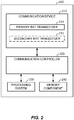
- FIG. 2 generally illustrates an access terminal 200 configured to compose, share, and/or utilize network feedback information using a D2D link in accordance with an aspect of the disclosure.
- the access terminal 200 may be any wireless communication device allowing a user to communicate over a communications network (for example, a mobile phone, router, personal computer, server, entertainment device, Internet of Things (IOT) / Internet of Everything (IOE) capable device, in-vehicle communication device, etc .)).
- the access terminal 200 may operate according to one or several radio access technologies (RATs).
- RATs radio access technologies
- the access terminal 200 generally includes a communication device 210 for communicating with other network nodes via at least one designated RAT.
- the communication device 210 may be variously configured for transmitting and encoding signals (for example, messages, indications, information, etc .), and, conversely, for receiving and decoding signals (for example, messages, indications, information, pilots, etc .) in accordance with the designated RAT.
- the access terminal 200 may also generally include a communication controller 220 for controlling operation of the communication device 210 (for example, directing, modifying, enabling, disabling, etc .).
- the communication controller 220 may operate independently from the host system functionality, illustrated as a processing system 230 and a memory component 240. Additionally or alternatively, the communication controller 220 may operate at the direction of, or otherwise in conjunction with, respective host system functionality. In some designs, the communication controller 220 may be partly or wholly subsumed by the respective host system functionality.
- the communication device 210 includes two co-located transceivers operating according to respective RATs, including a primary-RAT transceiver 211 and an optional secondary-RAT transceiver 212.
- a "transceiver” may include a transmitter circuit, a receiver circuit, or a combination thereof, but need not provide both transmit and receive functionalities in all designs.
- a low functionality receiver circuit may be employed in some designs to reduce costs when providing full communication is not necessary (for example, a WiFi chip or similar circuitry simply providing low-level sniffing).
- co-located for example, radios, access points, transceivers, etc .
- an interface for example, an Ethernet switch
- the primary-RAT transceiver 211 and the secondary-RAT transceiver 212 may provide different functionalities and may be used for different purposes.
- the primary-RAT transceiver 211 may operate in accordance with Long-Term Evolution (LTE) technology to provide communication with other nodes
- the secondary-RAT transceiver 212 may operate in accordance with WiFi technology to provide communication with other nodes.
- LTE Long-Term Evolution
- WiFi Wireless Fidelity
- the primary-RAT transceiver 211 and the secondary-RAT transceiver 212 may provide functionalities for LTE-Direct or WiFi-Direct D2D communications, respectively.
- FIG. 3 generally illustrates a method 300 for sharing network feedback information in accordance with an aspect of the disclosure.
- the method 300 may be performed by an access terminal, for example, the access terminal 150 of FIG. 1 , the access terminal 160 of FIG. 1 , the access terminal 200 of FIG. 2 , or any other device in the present disclosure. However, for the purposes of illustration, the method 300 will be described below as it would be performed by the access terminal 160 of FIG. 1 .
- the access terminal 160 establishes a wireless link with an access point.
- the access point may be analogous to, for example, the access point 110 of FIG. 1 , the access point 120 of FIG. 1 , the access point 130 of FIG. 1 , or any other device in the present disclosure.
- the method 300 will be described below as if the access terminal 160 had established the wireless link 162 with the access point 120 (as depicted in FIG. 1 ).
- the access terminal 160 may establish the wireless link 162 with the access point 120 using a transceiver analogous to the primary-RAT transceiver 211 of FIG. 2 , which may be configured to operate in accordance with LTE.
- the establishing at 310 may be performed by any suitable transceiver included in the access terminal 160, for example, a primary-RAT transceiver (such as the primary-RAT transceiver 211 depicted in FIG. 2 ) or a secondary-RAT transceiver such as the secondary-RAT transceiver 212 depicted in FIG. 2 ).
- the transceiver that performs the establishing at 310 may also work in tandem with at least one processor (analogous to, for example, the processing system 230 of FIG. 2 ) and/or at least one memory (analogous to, for example, the memory component 240 of FIG. 2 ).
- the access terminal 160 receives network configuration data from the access point 120.
- the network configuration data may be gathered from synchronization signals (for example, a Primary Synchronization Signal (PSS), a Secondary Synchronization Signal (SSS), etc .)), information blocks (for example, a Master Information Block (MIB) or one or more System Information Blocks (SIBx), etc .)), or any other signal that carries data associated with a network configuration of the access point 120 (acknowledgements, control signals, beacons, registration signals, paging messages, etc .).
- the network configuration data may include indicators as to what network services (voice, data, SMS, etc .) are provided by the access point 120.
- the receiving at 320 may be performed by any suitable transceiver included in the access terminal 160, for example, a primary-RAT transceiver (such as the primary-RAT transceiver 211 depicted in FIG. 2 ) or a secondary-RAT transceiver (such as the secondary-RAT transceiver 212 depicted in FIG. 2 ).
- the transceiver that performs the receiving at 320 may also work in tandem with at least one processor (analogous to, for example, the processing system 230 of FIG. 2 ) and/or at least one memory (analogous to, for example, the memory component 240 of FIG. 2 ).
- the access terminal 160 optionally monitors the wireless link 162 that was established at 310.
- the monitoring of the wireless link 162 may include the monitoring of one or more characteristics of the wireless link 162, for example, frequency, timing, quality, availability, etc.
- the one or more characteristics of the wireless link 162 may be measured and/or recorded using any suitable technique, and may be discarded after a certain period of time or maintained indefinitely.
- the monitoring at 330 may be performed by any suitable transceiver included in the access terminal 160, for example, a primary-RAT transceiver (such as the primary-RAT transceiver 211 depicted in FIG. 2 ) or a secondary-RAT transceiver (such as the secondary-RAT transceiver 212 depicted in FIG. 2 ).
- the transceiver that performs the monitoring at 330 may also work in tandem with at least one processor (analogous to, for example, the processing system 230 of FIG. 2 ) and/or at least one memory (analogous to, for example, the memory component 240 of FIG. 2 ).
- the one or more characteristics of the wireless link 162 may be recorded in at least one memory (analogous to, for example, the memory component 240 of FIG. 2 ).
- the access terminal 160 composes a network feedback expression (NFE) that indicates a status or availability of at least one network service associated with the access point 120.
- the composing at 340 may be based on the network configuration data received at 320 from the access point 120. Additionally or alternatively, the composing at 340 may be based on the monitoring at 330 of the wireless link 162. For example, the access terminal 160 may evaluate the network configuration data received at 320, select information relating to the status or availability of one or more specific network services, and include that information in the NFE. Additionally or alternatively, the access terminal 160 may generate information relating to the status or availability of one or more specific network services based on the monitoring at 330 of the wireless link 162, and include that information in the NFE.
- NFE network feedback expression
- the NFE may be organized such that information relating to the status or availability of a specific network service is used to populate a specific data field in the NFE.
- the NFE may include a sequence of characters, and a specific data field may be located at a predefined position within the sequence of characters.
- the composing at 340 may be performed by at least one processor (analogous to, for example, the processing system 230 of FIG. 2 ) and/or at least one memory (analogous to, for example, the memory component 240 of FIG. 2 ).
- the access terminal 160 optionally receives an NFE request from a second access terminal via a D2D link.
- the second access terminal may be analogous to, for example, the access terminal 150 of FIG. 1 , the access terminal 200 of FIG. 2 , or any other device in the present disclosure.
- the method 300 will be described below as if the access terminal 160 had received the NFE request from the access terminal 150 on the D2D link 156.
- the receiving at 350 may be performed by any suitable transceiver included in the access terminal 160, for example, a primary-RAT transceiver (such as the primary-RAT transceiver 211 depicted in FIG. 2 ) or a secondary-RAT transceiver (such as the secondary-RAT transceiver 212 depicted in FIG. 2 ).
- the transceiver that performs the receiving at 350 may also work in tandem with at least one processor (analogous to, for example, the processing system 230 of FIG. 2 ) and/or at least one memory (analogous to, for example, the memory component 240 of FIG. 2 ).
- the access terminal 160 may establish the wireless link 162 with the access point 120 using a transceiver analogous to the primary-RAT transceiver 211 of FIG. 2 , which may be configured to operate in accordance with LTE.
- the access terminal 160 may also establish the D2D link 156 with the access terminal 150 using the primary-RAT transceiver 211 of FIG. 2 .
- the resulting D2D link 156 may be, for example, an LTE-Direct wireless link.
- the access terminal 160 may establish the D2D link 156 with the access terminal 150 using the secondary-RAT transceiver 212 of FIG. 2 , which may be configured to operate in accordance with, for example, WiFi or Bluetooth.
- the resulting D2D link 156 may be, for example, a WiFi-Direct wireless link or a Bluetooth Low Energy wireless link.
- the access terminal 160 transmits the NFE to the access terminal 150 via the D2D link 156.
- the transmitting at 360 may be intermittent (for example, periodic) and the commencement of intermittent transmitting of the NFE may be responsive to the establishment of the D2D link 156. Additionally or alternatively, the transmitting at 360 may be responsive to the receiving of an NFE request at 350. In either case, the transmitting at 360 may comprise one or more of a broadcast to every member of a D2D group or a targeted transmission to one or more specific members of a D2D group.
- the optional receiving at 350 and the transmitting at 360 may be preceded by the establishing of the D2D link 156 between the access terminal 160 and the access terminal 150.
- the establishing of the D2D link 156 may be performed in accordance with any suitable protocol (for example, LTE-Direct, WiFi-Direct, Bluetooth, Bluetooth Low Energy, etc .).
- LTE-Direct Wireless link the access terminal 150 and the access terminal 160 may separately perform service authorization signaling with the network (for example, with the access points 110, 120, and/or 130); discover one another through the announcing, requesting, and/or monitoring of D2D availability; and establish the D2D link 156 after performing a match report.
- example protocols for establishing a D2D link and transmitting/receiving thereon can be found in the Third-Generation Partnership Project's technical specifications 23.303, the WiFi Alliance Peer-to-Peer Services (P2Ps) Technical Specification, etc.
- FIG. 4 generally illustrates a method 400 for composing a network feedback expression (NFE) in accordance with an aspect of the disclosure.
- the method 400 may be used to perform the composing at 330 (depicted in FIG. 3 ).
- the method 400 may be performed by an access terminal, for example, the access terminal 150 of FIG. 1 , the access terminal 160 of FIG. 1 , the access terminal 200 of FIG. 2 , or any other device in the present disclosure. However, for the purposes of illustration, the method 400 will be described below as it would be performed by the access terminal 160.
- the method 400 may be performed in response to successful establishment of the wireless link 162 with the access point 120 (as at 310 of FIG. 3 ) and/or receipt of network configuration data (as at 320 of FIG. 3 ). Additionally or alternatively, the method 400 may be performed intermittently (for example, periodically), or upon receipt of a NFE request (as at 350 of FIG. 3 ).
- the access terminal 160 generates access point identifier information associated with a serving access point.
- the serving access point may be analogous to, for example, the access point 110 of FIG. 1 , the access point 120 of FIG. 1 , the access point 130 of FIG. 1 , or any other device in the present disclosure. However, for the purposes of illustration, the method 400 will be described below as if the access point 120 were the serving access point for the access terminal 160.
- the access terminal 160 may establish a wireless link with the access point 120 (for example, as depicted at 310 in FIG. 3 ) and/or receive network configuration data from the access point 120 (for example, as depicted at 320 in FIG. 3 ).
- the access terminal 160 identifies the access point 120 based on the network configuration data.
- the network configuration data may include an access point identifier.
- the access point identifier may be specific to the access point 120 and may serve to differentiate the access point 120 from other access points (for example, the access point 110 and the access point 130).
- the access point identifier may include, for example, a Public Land Mobile Network (PLMN) code, physical cell identifier (PCI), and/or an Evolved Universal Terrestrial Access Network Absolute Radio Frequency Channel Number (EARFCN).
- PLMN Public Land Mobile Network
- PCI physical cell identifier
- Evolved Universal Terrestrial Access Network Absolute Radio Frequency Channel Number Evolved Universal Terrestrial Access Network Absolute Radio Frequency Channel Number
- the access terminal 160 generates radio link failure (RLF) feedback information.
- the access point 120 will intermittently (for example, periodically) indicate whether a cell associated with the access point 120 is barred or not barred. The indication as to whether the cell is barred may be included, for example, in the network configuration data received at 320 (for example, in a SIB2 block). If the access point 120 indicates that the cell is barred, then the access terminal 160 may not camp on the access point 120, and if the cell is not barred, then the access terminal 160 may camp on the access point 120. In accordance with an aspect of the disclosure, the access terminal 160 may generate RLF feedback information that indicates whether the cell associated with the access point 120 is barred or not barred. As will be discussed in greater detail below, the RLF feedback information may be used to compose an NFE.
- the access terminal 160 may also monitor whether the cell is barred or not barred over time. The monitoring may be performed, for example, by recording over time the indications from the access point 120 as to whether the cell is barred or not barred.
- the RLF feedback information may include information as to whether the cell associated with the access point 120 is barred, and may further include information as to whether the cell has been barred for a time period that exceeds a cell bar threshold.
- the access terminal 160 maps the RLF feedback information generated at 420 into one or more binary sequences.
- a RLF feedback binary sequence may have a length of two bits, wherein '00' indicates that the cell is not barred, '01' indicates that the cell is barred for a period of time that does not exceed the cell bar threshold, '10' indicates that the cell has been barred for a period of time that exceeds the cell bar threshold, and '11' indicates that the RLF status of the access point 120 is unknown.
- a RLF feedback binary sequence may have a length of two bits, wherein '00' indicates that the cell is not barred, '01' indicates that the cell is barred for a period of time that does not exceed the cell bar threshold, '10' indicates that the cell has been barred for a period of time that exceeds the cell bar threshold, and '11' indicates that the RLF status of the access point 120 is unknown.
- the one or more binary sequences mapped at 422 may be of any length and the information therein
- the access terminal 160 generates voice feedback information.
- the access point 120 will intermittently (for example, periodically) indicate whether the access point 120 supports voice service.
- the indication as to whether the access point 120 supports voice service may be included, for example, in the network configuration data received at 320.
- the voice feedback information generated by the access terminal 160 at 430 may therefore include voice service support information.
- the access point 120 may indicate whether the access point 120 supports voice service in an attach accept message for Voice over IP (VOIP) and/or Single Radio Voice Call Continuity (SRVCC) received by the access terminal 160.
- VOIP Voice over IP
- SSVCC Single Radio Voice Call Continuity
- a Mobility Management Entity may send an Initial Context Setup Request message (as specified in, for example, 3GPP TS 23.216) that includes a SRVCC Operation Possible Information Element (IE), thereby indicating that the ability access point 120 has the ability to perform SRVCC.
- IE SRVCC Operation Possible Information Element
- 1xCSFB 1x Circuit-Switch Fallback
- the access point 120 may indicate the voice service type that is supported. Examples of a voice service type include Voice over IP (VOIP), 1x Circuit-Switch Fallback (1xCSFB), enhanced 1xCSFB (elxCSFB), and Third Generation Partnership Project Circuit-Switch Fallback (3GPP CSFB), although it will be understood that other voice service types may be indicated.
- VOIP Voice over IP
- 1xCSFB 1x Circuit-Switch Fallback
- elxCSFB enhanced 1xCSFB
- 3GPP CSFB Third Generation Partnership Project Circuit-Switch Fallback
- the access terminal 160 may determine whether VOIP is supported based on an indication that a successful registration for Internet Protocol Multimedia Subsystem (IMS) has been performed.
- IMS Internet Protocol Multimedia Subsystem
- the indication as to the type of voice service supported by the access point 120 may be included, for example, in the network configuration data received at 320 (as noted above).
- the voice feedback information generated by the access terminal 160 at 430 may therefore include voice service type information.
- the access point 120 may indicate whether the access point 120 supports Single Radio Voice Call Continuity (SRVCC).
- SRVCC Single Radio Voice Call Continuity
- the indication as to whether the access point 120 supports SRVCC may be included, for example, in the network configuration data received at 320 (as noted above).
- the voice feedback information generated by the access terminal 160 at 430 may therefore include SRVCC support information.
- the access terminal 160 may also monitor call failures to generate voice service quality information.
- the monitoring may be performed, for example, by recording over time a number of call failures experienced by the access terminal 160 when using the voice service supported by the access point 120.
- the access terminal 160 may generate voice service quality information based on whether the number of call failures experienced over a certain duration of time exceeds a call failure threshold.
- the voice feedback information generated by the access terminal 160 at 430 may therefore include voice service quality information.
- the access terminal 160 maps the voice service feedback information generated at 430 into one or more binary sequences.
- a voice service support sequence may have a length of two bits, wherein '00' indicates that the access point 120 supports voice service, '01' indicates that the access point 120 does not support voice service, and '11' indicates that the voice service support status of the access point 120 is unknown.
- a voice service type sequence may have a length of two bits, wherein '00' indicates that the access point 120 supports VOIP voice service, '01' indicates that the access point 120 supports 1x Circuit Switch Fallback (1xCSFB) voice service, '10' indicates that the access point 120 supports 3GPP Gateway (GW) voice service, and '11' indicates that the voice service type of the access point 120 is unknown.
- a SRVCC support sequence may have a length of two bits, wherein '00' indicates that the access point 120 supports SRVCC, '01' indicates that the access point 120 does not support SRVCC, and '11' indicates that the SRVCC support status of the access point 120 is unknown.
- a voice service quality sequence may have a length of two bits, wherein '00' indicates that the voice service quality is good (for example, the number of call failures does not exceed the call failure threshold), '01' indicates that the voice service quality is bad (for example, the number of call failures exceeds the call failure threshold), and '11' indicates that the voice service quality of the access point 120 is unknown.
- the access terminal 160 generates data feedback information.
- the access point 120 will intermittently (for example, periodically) indicate whether the access point 120 supports data service.
- the indication as to whether the access point 120 supports data service may be included, for example, in the network configuration data received at 320 or determined by the access terminal 160 based on whether the access terminal 160 is able to connect to the access point 120 and obtain data service.
- the data feedback information generated by the access terminal 160 at 440 may therefore include data service status information.
- the access terminal 160 may monitor data service to generate data service quality information.
- the monitoring may be performed, for example, by recording over time a channel quality indicator (CQI) and/or a physical layer throughput experienced by the access terminal 160 on the wireless link 162.
- CQI channel quality indicator
- the access terminal 160 may generate data service quality information based on whether the average CQI over a certain duration of time exceeds a CQI sufficiency threshold. Additionally or alternatively, the access terminal 160 may generate data service quality information based on whether the actual physical layer throughput matches the expected physical layer throughput over a duration of time.
- the expected physical layer throughput may be based on, for example, the average CQI.
- the data feedback information generated by the access terminal 160 at 440 may therefore include data service quality information.
- the access terminal 160 maps the data service status information generated at 440 into one or more binary sequences.
- a data service status binary sequence may have a length of two bits, wherein '00' indicates that data service is supported, '01' indicates that data service is not supported, '10' indicates that data service is connected, and '11' indicates that data service is idle.
- the access terminal 160 maps the data service quality information generated at 440 into one or more binary sequences.
- a data service quality binary sequence may have a length of two bits, wherein '00' indicates that the data service quality is good (for example, the average CQI over a certain duration of time exceeds a CQI sufficiency threshold), '01' indicates that the voice service quality is bad (for example, the average CQI over a certain duration of time does not exceed a CQI sufficiency threshold), and '11' indicates that the voice service quality of the access point 120 is unknown.
- a data service quality binary sequence may have a length of two bits, wherein '00' indicates that the data service quality is good (for example, the average CQI over a certain duration of time exceeds the CQI sufficiency threshold), '01' indicates that the voice service quality is bad (for example, the average CQI does not meet the CQI sufficiency threshold), and '11' indicates that the voice service quality of the access point 120 is unknown.
- the access terminal 160 generates SMS feedback information.
- the access point 120 will intermittently (for example, periodically) indicate whether the access point 120 supports SMS service.
- the indication as to whether the access point 120 supports SMS service may be included, for example, in the network configuration data received at 320.
- the access point 120 may indicate whether the access point 120 supports SMS service in an attach accept message received by the access terminal 160.
- the SMS feedback information generated by the access terminal 160 at 450 may therefore include SMS service support information.
- the access point 120 may indicate the SMS service type that is supported.
- SMS service type examples include Internet Protocol Multimedia Subsystem (IMS), SMS over S102, and SMS Gateway (GW), although it will be understood that other SMS service types may be indicated.
- IMS Internet Protocol Multimedia Subsystem
- GW SMS Gateway
- the indication as to the type of SMS service supported by the access point 120 may be included, for example, in the network configuration data received at 320.
- the access point 120 may indicate the SMS service type that is supported in an attach accept message received by the access terminal 160.
- the SMS feedback information generated by the access terminal 160 at 430 may therefore include SMS service type information.
- the access terminal 160 maps the SMS service support information generated at 450 into one or more binary sequences.
- a SMS service status binary sequence may have a length of two bits, wherein '00' indicates that SMS service is supported, '01' indicates that SMS service is not supported, and '11' indicates that it is unknown whether the access point 120 supports SMS service.
- the access terminal 160 maps the SMS service type information generated at 450 into one or more binary sequences.
- a SMS service type binary sequence may have a length of two bits, wherein '00' indicates an IMS service type, '01' indicates an S102 service type, '10' indicates an SMS GW service type, and '11' indicates that the SMS service type of the access point 120 is unknown.
- the access terminal 160 composes a NFE segment associated with the access point 120 based on the one or more binary sequences that are mapped at 422, 432, 442, 452, or any combination thereof.
- the one or more binary sequences that are mapped at 422, 432, 442, and 452 are arranged within a larger binary sequence in accordance with a predetermined arrangement.
- the predetermined arrangement may specify that a predetermined number of bits at the beginning of the NFE segment constitute an access point identifier field that is to be populated with the access point identifier obtained at 410.
- the predetermined arrangement may further specify that the access point identifier field is followed by another predetermined number of bits which constitute a RLF feedback field, another predetermined number of bits which constitute a voice feedback field, yet another predetermined number of bits which constitute a data feedback field, and yet another predetermined number of bits which constitute a SMS feedback field.
- These fields may be populated with the one or more binary sequences that are mapped at 422, 432, 442, and 452 described above.
- FIG. 5 which will be described in greater detail below, generally illustrates an example of a predetermined arrangement that may be used to compose the NFE segment at 460.
- the access terminal 160 stores and/or maintains the NFE segment in a NFE database.
- the NFE segment is timestamped and may be discarded after a certain duration of time.
- the storing and/or maintaining at 470 may be performed by at least one processor (analogous to, for example, the processing system 230 of FIG. 2 ) and/or at least one memory (analogous to, for example, the memory component 240 of FIG. 2 ).
- the access terminal 160 optionally combines the NFE segment with one or more previously-composed NFE segments, for example, previously-composed NFE segments that are retrieved from the NFE database described above.
- each NFE segment consists of a binary sequence and is combined with the one or more previously-composed NFE segments by arranging them from end to end.
- the NFE segments may be ordered based on age (for example, an amount of time stored and/or maintained in the NFE database), proximity (for example, a distance from the access terminal 160 or the access point 120), or size (for example, a bandwidth or throughput of the access point 120).
- the access terminal 160 may have previously camped on the access point 130. After composing (at 460) the NFE segment associated with the access point 120, the access terminal 160 may combine it with a previously-composed NFE segment associated with the access point 130.
- the access terminal 160 composes a NFE from one or more NFE segments.
- the composing may include the providing of a header or expression code that identifies the binary sequence as a NFE.
- FIG. 5 which will be described in greater detail below, generally illustrates an example of a predetermined arrangement that may be used to compose the NFE at 490.
- the method 400 as depicted in FIG. 4 includes the generation of RLF feedback information at 420, the generation of voice feedback information at 430, the generation of data feedback information at 440, and the generation of SMS feedback information at 450, it will be understood that each of the respective generations are optional, and that the method 400 may include the generating of more or fewer types of information.
- FIG. 5 generally illustrates an example of a predetermined arrangement that may be used to compose an NFE 500.
- the NFE 500 includes a header 501 that identifies the NFE 500 as an NFE.
- the manner in which the header 501 identifies the NFE 500 as an NFE may depend on the D2D protocol over which the NFE 500 is to be transmitted.
- the NFE 500 further includes an NFE segment 510 associated with a first access point (for example, access point 120 as depicted in FIG. 1 ), an NFE segment 520 associated with a second access point (for example, access point 130 as depicted in FIG. 1 ), and an NFE segment 530 associated with a third access point.
- an NFE segment 510 associated with a first access point for example, access point 120 as depicted in FIG. 1
- an NFE segment 520 associated with a second access point for example, access point 130 as depicted in FIG. 1
- an NFE segment 530 associated with a third access point.
- Each of the NFE segments 510, 520, 530 may include a binary sequence in which each bit is mapped in accordance with a predetermined arrangement. In order to illustrate the predetermined arrangement, a detail of the NFE segment 510 is depicted in FIG. 5 . However, it will be understood that each of the NFE segments 510, 520, 530 may be composed in accordance with the same predetermined arrangement.
- the predetermined arrangement may specify that a predetermined number of bits at the beginning of the NFE segment 510 may constitute an access point identifier field 511 that is to be populated with the access point identifier obtained at 410.
- the predetermined arrangement may further specify that the access point identifier field 511 is followed by another predetermined number of bits which constitute a RLF feedback field 512, another predetermined number of bits which constitute a voice feedback field 513, yet another predetermined number of bits which constitute a data feedback field 514, and yet another predetermined number of bits which constitute a SMS feedback field 515.
- fields 512, 513, 514, 515 may be populated with the RLF feedback information generated at 420, the voice feedback information generated at 430, the data feedback information generated at 440, and the SMS feedback information generated at 450, respectively.
- each of the fields may be populated with one or more of the binary sequences that are mapped at 422, 432, 442, and 452, as described above.
- each of the fields 512, 513, 514, 515 may be composed in accordance with the same predetermined arrangement.
- the predetermined arrangement may specify that within the voice feedback field 513, the first two bits may constitute a voice service support information field 516 (to return to an earlier example, '00' may indicate that voice service is supported on access point 120).
- the next two bits may constitute a voice service type information field 517 (to return to an earlier example, '00' may indicate that VOIP is the voice service type supported by access point 120).
- the next two bits may constitute a SRVCC support information field 518 (to return to an earlier example, '01' may indicate that the access point 120 does not support SRVCC).
- the next two bits may constitute a voice service quality field 519 (to return to an earlier example, '11' may indicate that the voice service quality of the access point 120 is unknown).
- FIG. 5 generally illustrates an example of a predetermined arrangement that may be used to compose the NFE 500.
- predetermined arrangements may be used to compose the NFE 500.
- Some fields may be omitted while other fields may be added.
- the sequence of the NFE segments 510, 520, 530 may be changed, the sequence of the fields 511, 512, 513, 514, 515 may be changed, and/or the sequence of the fields 516, 517, 518, 519 may be changed.
- FIG. 6 generally illustrates a method 600 for locating network services in accordance with an aspect of the disclosure.
- the method 600 may be performed by an access terminal, for example, the access terminal 150 of FIG. 1 , the access terminal 160 of FIG. 1 , the access terminal 200 of FIG. 2 , or any other device in the present disclosure. However, for the purposes of illustration, the method 600 will be described below as it would be performed by the access terminal 150 of FIG. 1 .
- the access terminal 150 identifies one or more desired network services.
- the access terminal 150 may desire to camp on an access point that is not barred, an access point that provides a specific voice service type, an access point that provides a certain level of channel quality, etc. If there are more than one desired network services, the access terminal 150 may also prioritize the desired network services, as will be described in greater detail below.
- the identifying and/or prioritizing at 610 may be performed by at least one processor (analogous to, for example, the processing system 230 of FIG. 2 ) and/or at least one memory (analogous to, for example, the memory component 240 of FIG. 2 ).
- the access terminal 150 establishes a D2D link with a second access terminal.
- the second access terminal may be analogous to, for example, the access terminal 160 of FIG. 1 , the access terminal 200 of FIG. 2 , or any other device in the present disclosure.
- the method 600 will be described below as if the access terminal 150 had established the D2D link 156 with the access terminal 160.
- the establishing of the D2D link 156 may be performed in accordance with any suitable protocol (for example, LTE-Direct, WiFi-Direct, Bluetooth, Bluetooth Low Energy, etc .).
- the access terminal 150 may establish the D2D link 156 with the access terminal 160 using a transceiver analogous to the primary-RAT transceiver 211 of FIG. 2 , which may be configured to operate in accordance with LTE.
- the establishing at 620 may be performed by any suitable transceiver included in the access terminal 160 (for example, a primary-RAT transceiver such as the primary-RAT transceiver 211 depicted in FIG. 2 ) or a secondary-RAT transceiver (such as the secondary-RAT transceiver 212 depicted in FIG. 2 ).
- the transceiver that performs the establishing at 620 may also work in tandem with at least one processor (analogous to, for example, the processing system 230 of FIG. 2 ) and/or at least one memory (analogous to, for example, the memory component 240 of FIG. 2 ).
- the access terminal 150 receives a network feedback expression (NFE) from the access terminal 160 via the D2D link 156, wherein the NFE indicates a status or availability of network services associated with an access point.
- NFE network feedback expression
- the access point may be analogous to, for example, the access point 110 of FIG. 1 , the access point 120 of FIG. 1 , the access point 130 of FIG. 1 , or any other device in the present disclosure.
- the method 600 will be described below as if the access terminal 150 had received the NFE indicating a status or availability of network services associated with the access point 120.
- the method 600 will be described below as if the NFE was arranged similarly to the NFE 500 depicted in FIG. 5 .
- the access terminal 150 may receive the NFE 500 using a transceiver analogous to the primary-RAT transceiver 211 of FIG. 2 , which may be configured to operate in accordance with LTE.
- the receiving at 630 may be performed by any suitable transceiver included in the access terminal 160 (for example, a primary-RAT transceiver such as the primary-RAT transceiver 211 depicted in FIG. 2 ) or a secondary-RAT transceiver (such as the secondary-RAT transceiver 212 depicted in FIG. 2 ).
- the transceiver that performs the receiving at 630 may also work in tandem with at least one processor (analogous to, for example, the processing system 230 of FIG. 2 ) and/or at least one memory (analogous to, for example, the memory component 240 of FIG. 2 ).
- the access terminal 150 stores and/or maintains the NFE 500 in a NFE database.
- the NFE 500 is broken down into the NFE segments 510, 520, 530.
- each NFE segment may be associated with a different access point.
- each NFE segment is timestamped and may be discarded after a certain duration of time.
- the storing and/or maintaining at 470 may be performed by at least one processor (analogous to, for example, the processing system 230 of FIG. 2 ) and/or at least one memory (analogous to, for example, the memory component 240 of FIG. 2 ).
- the access terminal 150 received the NFE 500 transmitted from the access terminal 160 (at 630) and stored and/or maintained the NFE segments 510, 520, 530 in the NFE database (at 632).
- Each of the NFE segments 510, 520, 530 potentially includes data indicating a status or availability of at least one network service associated with an access point. It will be understood that if the access terminal 150 determines to generate a NFE similar to the NFE 500 received from the access terminal 160 (for example, by performing a method similar to the method 300 depicted in FIG. 3 ), it may choose to include any of the NFE segments 510, 520, 530 stored and/or maintained in the NFE database.
- NFE segments 510, 520, 530 By including one or more of the NFE segments 510, 520, 530 received from access terminal 160 in a NFE and transmitting it to another access terminal (i.e., an access terminal other than access terminal 160), it acts as a relay for the NFE segments 510, 520, 530. It will be understood that by relaying NFE segments to other access terminals, a large amount of data indicating a status or availability of at least one network service associated with an access point can be rapidly disseminated. In a D2D group containing a plurality of members, it is only necessary for one member of the group to have generated an NFE segment associated with a particular access point. That NFE segment can be transmitted and/or relayed to each member of the D2D group, thereby conserving the resources which might otherwise be consumed in attempts to locate network services.
- the access terminal 150 determines, based on the NFE 500 received at 630, whether the access point 120 provides the one or more desired network services identified at 610.
- the access terminal 150 may determine whether the one or more desired network services are provided based on one or more of the RLF feedback information provided in the RLF feedback field 512, the voice feedback information provided in the voice feedback field 513, the data feedback information provided in the data feedback field 514, and/or the SMS feedback information provided in the SMS feedback field 515.
- this information may be provided by evaluating the sequence of characters provided in the NFE 500 received at 630.
- the information may be provided, for example, in the predetermined arrangement depicted in FIG. 5 .
- the method 600 proceeds to 650 (described below). If the access terminal 150 determines that the access point 120 does not provide the one or more desired network services ('no' at 640 of FIG. 6 ), then the method 600 proceeds to 660 (described below).
- the determining at 640 may be performed by at least one processor (analogous to, for example, the processing system 230 of FIG. 2 ) and/or at least one memory (analogous to, for example, the memory component 240 of FIG. 2 ).
- the access terminal 150 identifies the access point 120 and establishes a wireless link with the access point 120.
- the access point 120 may be identified based on an access point identifier provided in the access point identifier field 511.
- the access terminal 150 may establish the wireless link with the access point 120 using a transceiver analogous to the primary-RAT transceiver 211 of FIG. 2 , which may be configured to operate in accordance with LTE.
- the establishing at 650 may be performed by any suitable transceiver included in the access terminal 150, for example, a primary-RAT transceiver (such as the primary-RAT transceiver 211 depicted in FIG. 2 ) or a secondary-RAT transceiver such as the secondary-RAT transceiver 212 depicted in FIG. 2 ).
- the transceiver that performs the establishing at 650 may also work in tandem with at least one processor (analogous to, for example, the processing system 230 of FIG. 2 ) and/or at least one memory (analogous to, for example, the memory component 240 of FIG. 2 ).
- the access terminal 150 may avoid establishing a wireless link with the access point 120 if it has determined (based on the NFE 500 received at 630) that the access point 120 does not provide the desired network services. Conventionally, an access terminal would need to camp on the access point 120 and directly receive network configuration data in order to make this determination. However, in accordance with the method 600, the access terminal 150 may utilize the NFE 500 (received at 630 via the D2D link 156) to make the determination as to whether the access point 120 provides the one or more desired network services. In the event that the access point 120 does not provide the one or more desired network services, the access terminal 150 can terminate a search for the one or more desired network services, or attempt to locate them elsewhere. In either case, the access terminal 150 obtains the information necessary to make the determination without camping on the access point 120, which requires significant consumption of resources (power, processing, bandwidth, etc .).
- the access terminal 150 may transmit an NFE request to third access terminal via a D2D link. As noted above, the access terminal 150 may choose to continue searching for the one or more desired network services. In some implementations, the one or more desired network services may be located by transmitting an NFE request. The NFE request may be broadcast to the members of a D2D group. Additionally or alternatively, the access terminal 150 may establish a D2D group for the purposes of transmitting the NFE request. Additionally or alternatively, the access terminal 150 may transmit the NFE request to one or more specific members of a D2D group, for example, members that have not already provided an NFE.
- the NFE request may take the form of the NFE 500.
- the access terminal 150 and the access terminal 160 may be preconfigured to interpret an NFE received from a D2D correspondent as an NFE request.
- the access terminal 150 may transmit the NFE request using a transceiver analogous to the primary-RAT transceiver 211 of FIG. 2 , which may be configured to operate in accordance with LTE.
- the transmitting at 660 may be performed by any suitable transceiver included in the access terminal 160 (for example, a primary-RAT transceiver such as the primary-RAT transceiver 211 depicted in FIG. 2 ) or a secondary-RAT transceiver (such as the secondary-RAT transceiver 212 depicted in FIG. 2 ).
- the transceiver that performs the transmitting at 660 may also work in tandem with at least one processor (analogous to, for example, the processing system 230 of FIG. 2 ) and/or at least one memory (analogous to, for example, the memory component 240 of FIG. 2 ).
- the method 600 depicted in FIG. 6 depicts a scenario where a particular set of one or more desired network services is identified at 610, and the determination as to whether to establish a wireless link with the access point 120 is based on whether the access point 120 provides the particular set of one or more desired network services.
- the access terminal 150 may also prioritize the desired network services. In some implementations, it may be a high priority that the access point not be barred, and the access terminal 150 may determine that it will not attempt to camp on an access point that is barred.
- the access terminal 150 may determine that an access point associated with the certain level of channel quality is preferred, but that the certain level of channel quality is not a prerequisite condition for camping on the access point.
- the priorities may be set in any suitable manner.
- the access terminal 150 may be preconfigured to prioritize certain network services.
- the access terminal 150 may receive user indications (explicit or implicit) from a user of the access terminal 150 as to which network services are most desired.
- the access terminal 150 may use an access point scoring system to evaluate a plurality of access points in terms of the status and/or availability of a plurality of prioritized network services. For example, if the access point 120 is not barred and the access point 130 is barred, then the access terminal 150 may give a higher component score to the access point 120. Moreover, if the access point 120 supports data service with low channel quality and the access point 130 supports data service with high channel quality, then the access terminal 150 may give a higher component score to the access point 130. Additionally or alternatively, the component scores may be weighted based on priority and summed to generate an overall score for a particular access point. For example, if RLF is a greater priority than data quality, then the weight for the RLF component score may be greater than the weight for the data quality component score.
- DSP digital signal processor
- ASIC application specific integrated circuit
- FPGA field programmable gate array
- a general purpose processor may be a microprocessor, but in the alternative, the processor may be any conventional processor, controller, microcontroller, or state machine.
- a processor may also be implemented as a combination of computing devices, for example, a combination of a DSP and a microprocessor, a plurality of microprocessors, one or more microprocessors in conjunction with a DSP core, or any other such configuration.
- a software module may reside in RAM memory, flash memory, ROM memory, EPROM memory, EEPROM memory, registers, hard disk, a removable disk, a CD-ROM, or any other form of storage medium known in the art.
- An exemplary storage medium is coupled to the processor such that the processor can read information from, and write information to, the storage medium.
- the storage medium may be integral to the processor.
- the processor and the storage medium may reside in an ASIC.
- the ASIC may reside in an access terminal.
- the processor and the storage medium may reside as discrete components in a user terminal.
- the functions described herein may be implemented in hardware, software, firmware, or any combination thereof. If implemented in software, the functions may be stored on or transmitted over as one or more instructions or code on a computer-readable medium.
- Computer-readable media includes both computer storage media and communication media including any medium that facilitates transfer of a computer program from one place to another.
- a storage media may be any available media that can be accessed by a computer.
- such computer-readable media can comprise RAM, ROM, EEPROM, CD-ROM or other optical disk storage, magnetic disk storage or other magnetic storage devices, or any other medium that can be used to carry or store desired program code in the form of instructions or data structures and that can be accessed by a computer.
- any connection is properly termed a computer-readable medium.
- the software is transmitted from a website, server, or other remote source using a coaxial cable, fiber optic cable, twisted pair, digital subscriber line (DSL), or wireless technologies such as infrared, radio, and microwave
- the coaxial cable, fiber optic cable, twisted pair, DSL, or wireless technologies such as infrared, radio, and microwave are included in the definition of medium.
- Disk and disc includes compact disc (CD), laser disc, optical disc, digital versatile disc (DVD), floppy disk and blu-ray disc where disks usually reproduce data magnetically, while discs reproduce data optically with lasers. Combinations of the above should also be included within the scope of computer-readable media.
Description
- Aspects of this disclosure relate to wireless communication systems. In particular, aspects of this disclosure relate to composing, sharing, and/or utilizing network feedback information.
- Wireless communication systems have developed through various generations, including a first-generation analog wireless phone service (1G), a second-generation (2G) digital wireless phone service (including interim 2.5G and 2.75G networks) and third-generation (3G) and fourth-generation (4G) high speed data / Internet-capable wireless services. There are presently many different types of wireless communication systems in use, including Cellular and Personal Communications Service (PCS) systems.
- Examples of known cellular systems include the cellular Analog Advanced Mobile Phone System (AMPS), and digital cellular systems based on Code Division Multiple Access (CDMA), Frequency Division Multiple Access (FDMA), Time Division Multiple Access (TDMA), the Global System for Mobile Access (GSM) variation of TDMA, and newer hybrid digital communication systems using both TDMA and CDMA technologies. More recently, Long Term Evolution (LTE) has been developed as a wireless communication protocol for wireless communication of high-speed data for mobile phones and other data terminals. LTE is based on GSM, and includes contributions from various GSM-related protocols such as Enhanced Data rates for GSM Evolution (EDGE), and Universal Mobile Telecommunications System (UMTS) protocols such as High-Speed Packet Access (HSPA).
- In recent years, use of device-to-device (D2D) communications has increased. Examples of D2D communications (also known as peer-to-peer (P2P) communications)) include Bluetooth Low Energy (BTLE), WiFi-Direct, WiFi Aware, and LTE-Direct (LTE-D). D2D communication protocols enable access terminals to discover one another and establish a D2D network. Utilization of D2D networks enables the access terminals to continuously and passively share information while using less power and requiring less network presence. However, new ways of reducing power consumption and improving network performance are still in demand.
WO2016/000795 A1 discloses methods and devices for providing system information of a cellular communication network wherein the system information is transmitted from a node of the cellular communication to a user equipment and the cellular network node causes the user equipment to relay the system information to the further user equipment. - The following summary is an overview provided solely to aid in the description of various aspects of the disclosure and is provided solely for illustration of the aspects and not limitation thereof. The invention is embodied in the method of sharing network feedback information in a system comprising first access terminal, an access point and a second access terminal of
independent claim 1. Further, the invention is embodied in the method of locating network services in a system comprising a first access terminal, an access point and a second access terminal of independent claim 10. Further, the invention is embodied in an apparatus for sharing network feedback information of independent claim 14. Further, the invention is embodied in the apparatus for locating network services of independent claim 15. Further, the invention is embodied in the system of independent claim 16 and in the related method of independent claim 17. - A more complete appreciation of embodiments of the invention and many of the attendant advantages thereof will be readily obtained as the same becomes better understood by reference to the following detailed description when considered in connection with the accompanying drawings which are presented solely for illustration and not limitation of the invention, and in which:
-
FIG. 1 generally illustrates a wireless environment in which access terminals compose, share, and/or utilize network feedback information in accordance with an aspect of the disclosure. -
FIG. 2 generally illustrates examples of an access terminal in accordance with aspects of the disclosure. -
FIG. 3 generally illustrates a flow diagram for sharing network feedback information in accordance with an aspect of the disclosure. -
FIG. 4 generally illustrates a flow diagram for composing a network feedback expression (NFE) in accordance with an aspect of the disclosure. -
FIG. 5 generally illustrates an example of a predetermined arrangement that may be used to compose an NFE. -
FIG. 6 generally illustrates a flow diagram for locating network services in accordance with an aspect of the disclosure. - Aspects of the invention disclosed in the following description and related drawings are directed to specific embodiments of the invention. Alternate embodiments may be devised without departing from the scope of the invention. Additionally, well-known elements of the invention will not be described in detail, or will be omitted, so as not to obscure the relevant details of the invention. The words "exemplary" and/or "example" are used herein to mean "serving as an example, instance, or illustration." Any embodiment described herein as "exemplary" and/or "example" is not necessarily to be construed as preferred or advantageous over other embodiments. Likewise, the term "embodiments of the invention" does not require that all embodiments of the invention include the discussed feature, advantage, or mode of operation. Further, many embodiments are described in terms of sequences of actions to be performed by, for example, elements of a computing device. It will be recognized that various actions described herein can be performed by specific circuits (for example, application specific integrated circuits (ASICs)), by program instructions being executed by one or more processors, or by a combination of both. Additionally, the sequence of actions described herein can be considered to be embodied entirely within any form of computer-readable storage medium having stored therein a corresponding set of computer instructions that upon execution would cause an associated processor to perform the functionality described herein. Thus, the various aspects of the invention may be embodied in a number of different forms, all of which have been contemplated to be within the scope of the claimed subject matter. In addition, for each of the embodiments described herein, the corresponding form of any such embodiments may be described herein as, for example, "logic configured to" perform the described action.
- An access terminal may be mobile or stationary, and may communicate with a radio access network (RAN). As used herein, the term "access terminal" may be referred to interchangeably as an "access terminal" or "AT", a "wireless device", a "subscriber device", a "subscriber terminal", a "subscriber station", a "user terminal" or "UT", a "user equipment" or "UE", a "mobile terminal", a "mobile station", or variations thereof. Generally, access terminals can communicate with a core network via the RAN, and through the core network the access terminals can be connected with external networks such as the Internet. Of course, other mechanisms of connecting to the core network and/or the Internet are also possible for the access terminals, such as over wired access networks, WiFi networks (for example, based on IEEE 802.11, etc.) and so on. Access terminals can be embodied by any of a number of types of devices including but not limited to PC cards, compact flash devices, external or internal modems, wireless or wireline phones, and so on.
- The access terminal may communicate with the RAN via an access point. As used herein, the term "access point" may be referred to interchangeably as an "access point" or "AP", a "base station" or "BS", an "access point base station", a "Node B", an "eNode B", a "home base station", a "home Node B", a "femto cell" or "pico cell", or variations thereof. Generally, access points can relay data from the core network and the RAN to access terminals and vice-versa.
-
FIG. 1 generally illustrates awireless environment 100 that includes afirst access point 110, asecond access point 120, and athird access point 130. Theaccess point 110 is associated with acoverage area 111, theaccess point 120 is associated with acoverage area 121, and theaccess point 130 is associated with acoverage area 131. A coverage area may sometimes be referred to as a "cell". Although therespective access points respective access points respective coverage areas respective access points - Also depicted in
FIG. 1 is anaccess terminal 150 and anaccess terminal 160. Although therespective access terminals respective access terminals - Generally, the
respective access points respective coverage areas FIG. 1 , theaccess terminal 150 may be within thecoverage area 111 of theaccess point 110 and may establish (or may have previously established) awireless link 151 with theaccess point 110. Thewireless link 151 may be used by theaccess terminal 150 and theaccess point 110 to wirelessly exchange data. Similarly, theaccess terminal 160 may be in or near thecoverage areas respective access points access terminal 160 may establish (or may have previously established) awireless link 162 with theaccess point 120 and/or awireless link 163 with theaccess point 130. - The access terminal 150 (which, as depicted in
FIG. 1 , has already established thewireless link 151 with access point 110) may wish to establish a new wireless link with a different access point, for example, theaccess point 120 or theaccess point 130. In some implementations, theaccess terminal 150 may be mobile and may determine that a handover should be performed as it passes further away from theaccess point 110 and closer to theaccess point 120 or theaccess point 130. In some implementations, theaccess terminal 150 may determine that thewireless link 151 is insufficient and that a supplemental wireless link is necessary. In some implementations, theaccess terminal 150 may determine that theaccess point 110 does not provide desired network services. Although the reasons may vary, it will be understood that under certain circumstances, theaccess terminal 150 may wish to establish a new wireless link with a different access point. - As noted above, the
access terminal 150 may desire specific network services or require a specific level of network performance. For example, theaccess terminal 150 may require an access point with a certain radio link failure (RLF) status or may require that a specific service functionality such as voice, data, or short message service (SMS), is supported. Conventionally, theaccess terminal 150 may camp on a new access point, for example, theaccess point 120, and obtain network configuration data therefrom. Based on the network configuration data obtained from theaccess point 120, theaccess terminal 150 may then determine whether theaccess point 120 can provide the network services desired by theaccess terminal 150 and/or meet the desired network performance of theaccess terminal 150. If theaccess terminal 150 determines that theaccess point 120 can not meet its service or performance needs, then theaccess terminal 150 may detach from theaccess point 120 and repeat the process with another new access point, for example, theaccess point 130. Although theaccess terminal 150 may eventually find a satisfactory access point through trial and error, the process may result in unnecessary power and resource consumption. - In accordance with an aspect of the disclosure, the
access terminal 150 may determine whether a different access point can meet its service or performance needs without camping on it and obtaining network configuration data directly therefrom. Instead, theaccess terminal 150 may obtain the data from another access terminal, for example theaccess terminal 160, using aD2D link 156. - Access terminals such as the
access terminal 150 and theaccess terminal 160 may form or join a D2D group including any number of access terminals. Members of the D2D group may broadcast signals such that they are received by each wireless device in the D2D group, transmit signals directly to a specific wireless device in the D2D group, relay signals from one wireless device in the D2D group to another wireless device in the D2D group, etc. The formation or joining of the D2D group may be performed using any suitable protocol, but generally begins with discovery of other D2D-capable devices. For example, discovery can be performed in accordance with the technical specifications set forth by the Third-Generation Partnership Project (for example, 3GPP TS 23.303, "Proximity-based services (ProSe); Stage 2")), the WiFi Alliance (for example, WiFi Peer-to-Peer Services (P2Ps) Technical Specification)), or any other suitable standard-setter. The above-noted discovery techniques may be known by other names. Moreover, other variations and/or alternatives are known. A non-exclusive list of suitable discovery protocols includes LTE-Direct discovery protocol, WiFi-Direct discovery protocol, AllJoyn discovery protocol, WiFi Aware discovery protocol, Bluetooth discovery protocol, and Bluetooth Low Energy discovery protocol. - Once discovery has been performed by, for example, the
access terminal 150 and theaccess terminal 160, the D2D link 156 may be established therebetween. Different D2D protocols have different ranges. However, it will be understood that, in some scenarios, the D2D link 156 may be established independently of thecoverage areas FIG. 1 , it is not necessary for theaccess terminal 150 and theaccess terminal 160 to share a coverage area in order to establish theD2D link 156. Moreover, the RAT used to establish the D2D link 156 may be the same or different from the RAT used to establish thewireless link 151, thewireless link 162, and/or thewireless link 163. -
FIG. 2 generally illustrates anaccess terminal 200 configured to compose, share, and/or utilize network feedback information using a D2D link in accordance with an aspect of the disclosure. In general, theaccess terminal 200 may be any wireless communication device allowing a user to communicate over a communications network (for example, a mobile phone, router, personal computer, server, entertainment device, Internet of Things (IOT) / Internet of Everything (IOE) capable device, in-vehicle communication device, etc.)). Theaccess terminal 200 may operate according to one or several radio access technologies (RATs). - The
access terminal 200 generally includes acommunication device 210 for communicating with other network nodes via at least one designated RAT. Thecommunication device 210 may be variously configured for transmitting and encoding signals (for example, messages, indications, information, etc.), and, conversely, for receiving and decoding signals (for example, messages, indications, information, pilots, etc.) in accordance with the designated RAT. Theaccess terminal 200 may also generally include acommunication controller 220 for controlling operation of the communication device 210 (for example, directing, modifying, enabling, disabling, etc.). Thecommunication controller 220 may operate independently from the host system functionality, illustrated as aprocessing system 230 and amemory component 240. Additionally or alternatively, thecommunication controller 220 may operate at the direction of, or otherwise in conjunction with, respective host system functionality. In some designs, thecommunication controller 220 may be partly or wholly subsumed by the respective host system functionality. - In the example of
FIG. 2 , thecommunication device 210 includes two co-located transceivers operating according to respective RATs, including a primary-RAT transceiver 211 and an optional secondary-RAT transceiver 212. As used herein, a "transceiver" may include a transmitter circuit, a receiver circuit, or a combination thereof, but need not provide both transmit and receive functionalities in all designs. For example, a low functionality receiver circuit may be employed in some designs to reduce costs when providing full communication is not necessary (for example, a WiFi chip or similar circuitry simply providing low-level sniffing). Further, as used herein, the term "co-located" (for example, radios, access points, transceivers, etc.) may refer to one of various arrangements. For example, components that are in the same housing; components that are hosted by the same processor; components that are within a defined distance of one another; and/or components that are connected via an interface (for example, an Ethernet switch) where the interface meets the latency requirements of any required inter-component communication (for example, messaging). - The primary-
RAT transceiver 211 and the secondary-RAT transceiver 212 may provide different functionalities and may be used for different purposes. As an example, the primary-RAT transceiver 211 may operate in accordance with Long-Term Evolution (LTE) technology to provide communication with other nodes, while the secondary-RAT transceiver 212 may operate in accordance with WiFi technology to provide communication with other nodes. Additionally or alternatively, the primary-RAT transceiver 211 and the secondary-RAT transceiver 212 may provide functionalities for LTE-Direct or WiFi-Direct D2D communications, respectively. -
FIG. 3 generally illustrates amethod 300 for sharing network feedback information in accordance with an aspect of the disclosure. Themethod 300 may be performed by an access terminal, for example, theaccess terminal 150 ofFIG. 1 , theaccess terminal 160 ofFIG. 1 , theaccess terminal 200 ofFIG. 2 , or any other device in the present disclosure. However, for the purposes of illustration, themethod 300 will be described below as it would be performed by theaccess terminal 160 ofFIG. 1 . - At 310, the
access terminal 160 establishes a wireless link with an access point. The access point may be analogous to, for example, theaccess point 110 ofFIG. 1 , theaccess point 120 ofFIG. 1 , theaccess point 130 ofFIG. 1 , or any other device in the present disclosure. However, for the purposes of illustration, themethod 300 will be described below as if theaccess terminal 160 had established thewireless link 162 with the access point 120 (as depicted inFIG. 1 ). - In some implementations, the
access terminal 160 may establish thewireless link 162 with theaccess point 120 using a transceiver analogous to the primary-RAT transceiver 211 ofFIG. 2 , which may be configured to operate in accordance with LTE. However, the establishing at 310 may be performed by any suitable transceiver included in theaccess terminal 160, for example, a primary-RAT transceiver (such as the primary-RAT transceiver 211 depicted inFIG. 2 ) or a secondary-RAT transceiver such as the secondary-RAT transceiver 212 depicted inFIG. 2 ). The transceiver that performs the establishing at 310 may also work in tandem with at least one processor (analogous to, for example, theprocessing system 230 ofFIG. 2 ) and/or at least one memory (analogous to, for example, thememory component 240 ofFIG. 2 ). - At 320, the
access terminal 160 receives network configuration data from theaccess point 120. The network configuration data may be gathered from synchronization signals (for example, a Primary Synchronization Signal (PSS), a Secondary Synchronization Signal (SSS), etc.)), information blocks (for example, a Master Information Block (MIB) or one or more System Information Blocks (SIBx), etc.)), or any other signal that carries data associated with a network configuration of the access point 120 (acknowledgements, control signals, beacons, registration signals, paging messages, etc.). The network configuration data may include indicators as to what network services (voice, data, SMS, etc.) are provided by theaccess point 120. - The receiving at 320 may be performed by any suitable transceiver included in the
access terminal 160, for example, a primary-RAT transceiver (such as the primary-RAT transceiver 211 depicted inFIG. 2 ) or a secondary-RAT transceiver (such as the secondary-RAT transceiver 212 depicted inFIG. 2 ). The transceiver that performs the receiving at 320 may also work in tandem with at least one processor (analogous to, for example, theprocessing system 230 ofFIG. 2 ) and/or at least one memory (analogous to, for example, thememory component 240 ofFIG. 2 ). - At 330, the
access terminal 160 optionally monitors thewireless link 162 that was established at 310. The monitoring of thewireless link 162 may include the monitoring of one or more characteristics of thewireless link 162, for example, frequency, timing, quality, availability, etc. The one or more characteristics of thewireless link 162 may be measured and/or recorded using any suitable technique, and may be discarded after a certain period of time or maintained indefinitely. - The monitoring at 330 may be performed by any suitable transceiver included in the
access terminal 160, for example, a primary-RAT transceiver (such as the primary-RAT transceiver 211 depicted inFIG. 2 ) or a secondary-RAT transceiver (such as the secondary-RAT transceiver 212 depicted inFIG. 2 ). The transceiver that performs the monitoring at 330 may also work in tandem with at least one processor (analogous to, for example, theprocessing system 230 ofFIG. 2 ) and/or at least one memory (analogous to, for example, thememory component 240 ofFIG. 2 ). The one or more characteristics of thewireless link 162 may be recorded in at least one memory (analogous to, for example, thememory component 240 ofFIG. 2 ). - At 340, the
access terminal 160 composes a network feedback expression (NFE) that indicates a status or availability of at least one network service associated with theaccess point 120. The composing at 340 may be based on the network configuration data received at 320 from theaccess point 120. Additionally or alternatively, the composing at 340 may be based on the monitoring at 330 of thewireless link 162. For example, theaccess terminal 160 may evaluate the network configuration data received at 320, select information relating to the status or availability of one or more specific network services, and include that information in the NFE. Additionally or alternatively, theaccess terminal 160 may generate information relating to the status or availability of one or more specific network services based on the monitoring at 330 of thewireless link 162, and include that information in the NFE. - The NFE may be organized such that information relating to the status or availability of a specific network service is used to populate a specific data field in the NFE. For example, the NFE may include a sequence of characters, and a specific data field may be located at a predefined position within the sequence of characters.
- The composing at 340 may be performed by at least one processor (analogous to, for example, the
processing system 230 ofFIG. 2 ) and/or at least one memory (analogous to, for example, thememory component 240 ofFIG. 2 ). - At 350, the
access terminal 160 optionally receives an NFE request from a second access terminal via a D2D link. The second access terminal may be analogous to, for example, theaccess terminal 150 ofFIG. 1 , theaccess terminal 200 ofFIG. 2 , or any other device in the present disclosure. However, for the purposes of illustration, themethod 300 will be described below as if theaccess terminal 160 had received the NFE request from theaccess terminal 150 on theD2D link 156. - The receiving at 350 may be performed by any suitable transceiver included in the
access terminal 160, for example, a primary-RAT transceiver (such as the primary-RAT transceiver 211 depicted inFIG. 2 ) or a secondary-RAT transceiver (such as the secondary-RAT transceiver 212 depicted inFIG. 2 ). The transceiver that performs the receiving at 350 may also work in tandem with at least one processor (analogous to, for example, theprocessing system 230 ofFIG. 2 ) and/or at least one memory (analogous to, for example, thememory component 240 ofFIG. 2 ). - As noted above, in some implementations the
access terminal 160 may establish thewireless link 162 with theaccess point 120 using a transceiver analogous to the primary-RAT transceiver 211 ofFIG. 2 , which may be configured to operate in accordance with LTE. Theaccess terminal 160 may also establish the D2D link 156 with theaccess terminal 150 using the primary-RAT transceiver 211 ofFIG. 2 . The resulting D2D link 156 may be, for example, an LTE-Direct wireless link. - Additionally or alternatively, the
access terminal 160 may establish the D2D link 156 with theaccess terminal 150 using the secondary-RAT transceiver 212 ofFIG. 2 , which may be configured to operate in accordance with, for example, WiFi or Bluetooth. The resulting D2D link 156 may be, for example, a WiFi-Direct wireless link or a Bluetooth Low Energy wireless link. - At 360, the
access terminal 160 transmits the NFE to theaccess terminal 150 via theD2D link 156. The transmitting at 360 may be intermittent (for example, periodic) and the commencement of intermittent transmitting of the NFE may be responsive to the establishment of theD2D link 156. Additionally or alternatively, the transmitting at 360 may be responsive to the receiving of an NFE request at 350. In either case, the transmitting at 360 may comprise one or more of a broadcast to every member of a D2D group or a targeted transmission to one or more specific members of a D2D group. - As will be understood from the foregoing, the optional receiving at 350 and the transmitting at 360 may be preceded by the establishing of the D2D link 156 between the
access terminal 160 and theaccess terminal 150. The establishing of the D2D link 156 may be performed in accordance with any suitable protocol (for example, LTE-Direct, WiFi-Direct, Bluetooth, Bluetooth Low Energy, etc.). For example, to establish an LTE-Direct Wireless link, theaccess terminal 150 and theaccess terminal 160 may separately perform service authorization signaling with the network (for example, with theaccess points - Although the
method 300 is depicted as being performed in a particular sequence, it will be understood that this is solely for illustrative purposes, and themethod 300 may be performed in any logical sequence. -
FIG. 4 generally illustrates a method 400 for composing a network feedback expression (NFE) in accordance with an aspect of the disclosure. In some implementations, the method 400 may be used to perform the composing at 330 (depicted inFIG. 3 ). The method 400 may be performed by an access terminal, for example, theaccess terminal 150 ofFIG. 1 , theaccess terminal 160 ofFIG. 1 , theaccess terminal 200 ofFIG. 2 , or any other device in the present disclosure. However, for the purposes of illustration, the method 400 will be described below as it would be performed by theaccess terminal 160. The method 400 may be performed in response to successful establishment of thewireless link 162 with the access point 120 (as at 310 ofFIG. 3 ) and/or receipt of network configuration data (as at 320 ofFIG. 3 ). Additionally or alternatively, the method 400 may be performed intermittently (for example, periodically), or upon receipt of a NFE request (as at 350 ofFIG. 3 ). - At 410, the
access terminal 160 generates access point identifier information associated with a serving access point. The serving access point may be analogous to, for example, theaccess point 110 ofFIG. 1 , theaccess point 120 ofFIG. 1 , theaccess point 130 ofFIG. 1 , or any other device in the present disclosure. However, for the purposes of illustration, the method 400 will be described below as if theaccess point 120 were the serving access point for theaccess terminal 160. Prior to identifying theaccess point 120, theaccess terminal 160 may establish a wireless link with the access point 120 (for example, as depicted at 310 inFIG. 3 ) and/or receive network configuration data from the access point 120 (for example, as depicted at 320 inFIG. 3 ). - In some implementations, the
access terminal 160 identifies theaccess point 120 based on the network configuration data. For example, the network configuration data may include an access point identifier. The access point identifier may be specific to theaccess point 120 and may serve to differentiate theaccess point 120 from other access points (for example, theaccess point 110 and the access point 130). The access point identifier may include, for example, a Public Land Mobile Network (PLMN) code, physical cell identifier (PCI), and/or an Evolved Universal Terrestrial Access Network Absolute Radio Frequency Channel Number (EARFCN). - At 420, the
access terminal 160 generates radio link failure (RLF) feedback information. In some implementations, theaccess point 120 will intermittently (for example, periodically) indicate whether a cell associated with theaccess point 120 is barred or not barred. The indication as to whether the cell is barred may be included, for example, in the network configuration data received at 320 (for example, in a SIB2 block). If theaccess point 120 indicates that the cell is barred, then theaccess terminal 160 may not camp on theaccess point 120, and if the cell is not barred, then theaccess terminal 160 may camp on theaccess point 120. In accordance with an aspect of the disclosure, theaccess terminal 160 may generate RLF feedback information that indicates whether the cell associated with theaccess point 120 is barred or not barred. As will be discussed in greater detail below, the RLF feedback information may be used to compose an NFE. - At 420, the
access terminal 160 may also monitor whether the cell is barred or not barred over time. The monitoring may be performed, for example, by recording over time the indications from theaccess point 120 as to whether the cell is barred or not barred. In some implementations, the RLF feedback information may include information as to whether the cell associated with theaccess point 120 is barred, and may further include information as to whether the cell has been barred for a time period that exceeds a cell bar threshold. - At 422, the
access terminal 160 maps the RLF feedback information generated at 420 into one or more binary sequences. For example, a RLF feedback binary sequence may have a length of two bits, wherein '00' indicates that the cell is not barred, '01' indicates that the cell is barred for a period of time that does not exceed the cell bar threshold, '10' indicates that the cell has been barred for a period of time that exceeds the cell bar threshold, and '11' indicates that the RLF status of theaccess point 120 is unknown. However, it will be understood that this is an example provided solely for illustrative purposes, and that the one or more binary sequences mapped at 422 may be of any length and the information therein may be indicated using any specific sequence. - At 430, the
access terminal 160 generates voice feedback information. In some implementations, theaccess point 120 will intermittently (for example, periodically) indicate whether theaccess point 120 supports voice service. The indication as to whether theaccess point 120 supports voice service may be included, for example, in the network configuration data received at 320. The voice feedback information generated by theaccess terminal 160 at 430 may therefore include voice service support information. For example, theaccess point 120 may indicate whether theaccess point 120 supports voice service in an attach accept message for Voice over IP (VOIP) and/or Single Radio Voice Call Continuity (SRVCC) received by theaccess terminal 160. In some implementations, a Mobility Management Entity (MME) may send an Initial Context Setup Request message (as specified in, for example, 3GPP TS 23.216) that includes a SRVCC Operation Possible Information Element (IE), thereby indicating that theability access point 120 has the ability to perform SRVCC. In some implementations, 1x Circuit-Switch Fallback (1xCSFB) capability may be determined by theaccess terminal 160 based on SIB8 parameters and successful 1xCSFB registration. - Additionally or alternatively, the
access point 120 may indicate the voice service type that is supported. Examples of a voice service type include Voice over IP (VOIP), 1x Circuit-Switch Fallback (1xCSFB), enhanced 1xCSFB (elxCSFB), and Third Generation Partnership Project Circuit-Switch Fallback (3GPP CSFB), although it will be understood that other voice service types may be indicated. In some implementations, theaccess terminal 160 may determine whether VOIP is supported based on an indication that a successful registration for Internet Protocol Multimedia Subsystem (IMS) has been performed. The indication as to the type of voice service supported by theaccess point 120 may be included, for example, in the network configuration data received at 320 (as noted above). The voice feedback information generated by theaccess terminal 160 at 430 may therefore include voice service type information. - Additionally or alternatively, the
access point 120 may indicate whether theaccess point 120 supports Single Radio Voice Call Continuity (SRVCC). The indication as to whether theaccess point 120 supports SRVCC may be included, for example, in the network configuration data received at 320 (as noted above). The voice feedback information generated by theaccess terminal 160 at 430 may therefore include SRVCC support information. - Additionally or alternatively, the
access terminal 160 may also monitor call failures to generate voice service quality information. The monitoring may be performed, for example, by recording over time a number of call failures experienced by theaccess terminal 160 when using the voice service supported by theaccess point 120. Theaccess terminal 160 may generate voice service quality information based on whether the number of call failures experienced over a certain duration of time exceeds a call failure threshold. The voice feedback information generated by theaccess terminal 160 at 430 may therefore include voice service quality information. - At 432, the
access terminal 160 maps the voice service feedback information generated at 430 into one or more binary sequences. For example, a voice service support sequence may have a length of two bits, wherein '00' indicates that theaccess point 120 supports voice service, '01' indicates that theaccess point 120 does not support voice service, and '11' indicates that the voice service support status of theaccess point 120 is unknown. - Additionally or alternatively, a voice service type sequence may have a length of two bits, wherein '00' indicates that the
access point 120 supports VOIP voice service, '01' indicates that theaccess point 120 supports 1x Circuit Switch Fallback (1xCSFB) voice service, '10' indicates that theaccess point 120 supports 3GPP Gateway (GW) voice service, and '11' indicates that the voice service type of theaccess point 120 is unknown. - Additionally or alternatively, a SRVCC support sequence may have a length of two bits, wherein '00' indicates that the
access point 120 supports SRVCC, '01' indicates that theaccess point 120 does not support SRVCC, and '11' indicates that the SRVCC support status of theaccess point 120 is unknown. - Additionally or alternatively, a voice service quality sequence may have a length of two bits, wherein '00' indicates that the voice service quality is good (for example, the number of call failures does not exceed the call failure threshold), '01' indicates that the voice service quality is bad (for example, the number of call failures exceeds the call failure threshold), and '11' indicates that the voice service quality of the
access point 120 is unknown. - It will be understood that the particular sequences provided above are examples provided solely for illustrative purposes, and that the one or more binary sequences mapped at 432 may be of any length and the information therein may be indicated using any specific sequence.
- At 440, the
access terminal 160 generates data feedback information. In some implementations, theaccess point 120 will intermittently (for example, periodically) indicate whether theaccess point 120 supports data service. The indication as to whether theaccess point 120 supports data service may be included, for example, in the network configuration data received at 320 or determined by theaccess terminal 160 based on whether theaccess terminal 160 is able to connect to theaccess point 120 and obtain data service. The data feedback information generated by theaccess terminal 160 at 440 may therefore include data service status information. - Additionally or alternatively, the
access terminal 160 may monitor data service to generate data service quality information. The monitoring may be performed, for example, by recording over time a channel quality indicator (CQI) and/or a physical layer throughput experienced by theaccess terminal 160 on thewireless link 162. Theaccess terminal 160 may generate data service quality information based on whether the average CQI over a certain duration of time exceeds a CQI sufficiency threshold. Additionally or alternatively, theaccess terminal 160 may generate data service quality information based on whether the actual physical layer throughput matches the expected physical layer throughput over a duration of time. The expected physical layer throughput may be based on, for example, the average CQI. The data feedback information generated by theaccess terminal 160 at 440 may therefore include data service quality information. - At 442, the
access terminal 160 maps the data service status information generated at 440 into one or more binary sequences. For example, a data service status binary sequence may have a length of two bits, wherein '00' indicates that data service is supported, '01' indicates that data service is not supported, '10' indicates that data service is connected, and '11' indicates that data service is idle. - Additionally or alternatively, the
access terminal 160 maps the data service quality information generated at 440 into one or more binary sequences. For example, a data service quality binary sequence may have a length of two bits, wherein '00' indicates that the data service quality is good (for example, the average CQI over a certain duration of time exceeds a CQI sufficiency threshold), '01' indicates that the voice service quality is bad (for example, the average CQI over a certain duration of time does not exceed a CQI sufficiency threshold), and '11' indicates that the voice service quality of theaccess point 120 is unknown. As another example, a data service quality binary sequence may have a length of two bits, wherein '00' indicates that the data service quality is good (for example, the average CQI over a certain duration of time exceeds the CQI sufficiency threshold), '01' indicates that the voice service quality is bad (for example, the average CQI does not meet the CQI sufficiency threshold), and '11' indicates that the voice service quality of theaccess point 120 is unknown. - It will be understood that the particular sequences provided above are examples provided solely for illustrative purposes, and that the one or more binary sequences mapped at 442 may be of any length and the information therein may be indicated using any specific sequence.
- At 450, the
access terminal 160 generates SMS feedback information. In some implementations, theaccess point 120 will intermittently (for example, periodically) indicate whether theaccess point 120 supports SMS service. The indication as to whether theaccess point 120 supports SMS service may be included, for example, in the network configuration data received at 320. For example, theaccess point 120 may indicate whether theaccess point 120 supports SMS service in an attach accept message received by theaccess terminal 160. The SMS feedback information generated by theaccess terminal 160 at 450 may therefore include SMS service support information. - Additionally or alternatively, the
access point 120 may indicate the SMS service type that is supported. Examples of a SMS service type include Internet Protocol Multimedia Subsystem (IMS), SMS over S102, and SMS Gateway (GW), although it will be understood that other SMS service types may be indicated. The indication as to the type of SMS service supported by theaccess point 120 may be included, for example, in the network configuration data received at 320. For example, theaccess point 120 may indicate the SMS service type that is supported in an attach accept message received by theaccess terminal 160. The SMS feedback information generated by theaccess terminal 160 at 430 may therefore include SMS service type information. - At 452, the
access terminal 160 maps the SMS service support information generated at 450 into one or more binary sequences. For example, a SMS service status binary sequence may have a length of two bits, wherein '00' indicates that SMS service is supported, '01' indicates that SMS service is not supported, and '11' indicates that it is unknown whether theaccess point 120 supports SMS service. - Additionally or alternatively, the
access terminal 160 maps the SMS service type information generated at 450 into one or more binary sequences. For example, a SMS service type binary sequence may have a length of two bits, wherein '00' indicates an IMS service type, '01' indicates an S102 service type, '10' indicates an SMS GW service type, and '11' indicates that the SMS service type of theaccess point 120 is unknown. - It will be understood that the particular sequences provided above are examples provided solely for illustrative purposes, and that the one or more binary sequences mapped at 452 may be of any length and the information therein may be indicated using any specific sequence.
- At 460, the
access terminal 160 composes a NFE segment associated with theaccess point 120 based on the one or more binary sequences that are mapped at 422, 432, 442, 452, or any combination thereof. In some implementations, the one or more binary sequences that are mapped at 422, 432, 442, and 452 are arranged within a larger binary sequence in accordance with a predetermined arrangement. For example, the predetermined arrangement may specify that a predetermined number of bits at the beginning of the NFE segment constitute an access point identifier field that is to be populated with the access point identifier obtained at 410. The predetermined arrangement may further specify that the access point identifier field is followed by another predetermined number of bits which constitute a RLF feedback field, another predetermined number of bits which constitute a voice feedback field, yet another predetermined number of bits which constitute a data feedback field, and yet another predetermined number of bits which constitute a SMS feedback field. These fields may be populated with the one or more binary sequences that are mapped at 422, 432, 442, and 452 described above.FIG. 5 , which will be described in greater detail below, generally illustrates an example of a predetermined arrangement that may be used to compose the NFE segment at 460. - At 470, the
access terminal 160 stores and/or maintains the NFE segment in a NFE database. In some implementations, the NFE segment is timestamped and may be discarded after a certain duration of time. - The storing and/or maintaining at 470 may be performed by at least one processor (analogous to, for example, the
processing system 230 ofFIG. 2 ) and/or at least one memory (analogous to, for example, thememory component 240 ofFIG. 2 ). - At 480, the
access terminal 160 optionally combines the NFE segment with one or more previously-composed NFE segments, for example, previously-composed NFE segments that are retrieved from the NFE database described above. In some implementations, each NFE segment consists of a binary sequence and is combined with the one or more previously-composed NFE segments by arranging them from end to end. The NFE segments may be ordered based on age (for example, an amount of time stored and/or maintained in the NFE database), proximity (for example, a distance from theaccess terminal 160 or the access point 120), or size (for example, a bandwidth or throughput of the access point 120). As an example, theaccess terminal 160 may have previously camped on theaccess point 130. After composing (at 460) the NFE segment associated with theaccess point 120, theaccess terminal 160 may combine it with a previously-composed NFE segment associated with theaccess point 130. - At 490, the
access terminal 160 composes a NFE from one or more NFE segments. The composing may include the providing of a header or expression code that identifies the binary sequence as a NFE.FIG. 5 , which will be described in greater detail below, generally illustrates an example of a predetermined arrangement that may be used to compose the NFE at 490. - Although the method 400 as depicted in
FIG. 4 includes the generation of RLF feedback information at 420, the generation of voice feedback information at 430, the generation of data feedback information at 440, and the generation of SMS feedback information at 450, it will be understood that each of the respective generations are optional, and that the method 400 may include the generating of more or fewer types of information. -
FIG. 5 generally illustrates an example of a predetermined arrangement that may be used to compose anNFE 500. In this example, theNFE 500 includes aheader 501 that identifies theNFE 500 as an NFE. The manner in which theheader 501 identifies theNFE 500 as an NFE may depend on the D2D protocol over which theNFE 500 is to be transmitted. - The
NFE 500 further includes anNFE segment 510 associated with a first access point (for example,access point 120 as depicted inFIG. 1 ), anNFE segment 520 associated with a second access point (for example,access point 130 as depicted inFIG. 1 ), and anNFE segment 530 associated with a third access point. Although threeNFE segments FIG. 5 , it will be understood that this is solely for illustrative purposes, and that theNFE 500 may include any number of NFE segments. - Each of the
NFE segments NFE segment 510 is depicted inFIG. 5 . However, it will be understood that each of theNFE segments - As noted above, the predetermined arrangement may specify that a predetermined number of bits at the beginning of the
NFE segment 510 may constitute an accesspoint identifier field 511 that is to be populated with the access point identifier obtained at 410. The predetermined arrangement may further specify that the accesspoint identifier field 511 is followed by another predetermined number of bits which constitute aRLF feedback field 512, another predetermined number of bits which constitute avoice feedback field 513, yet another predetermined number of bits which constitute adata feedback field 514, and yet another predetermined number of bits which constitute aSMS feedback field 515. Thesefields - In order to illustrate how the binary sequences are used to populate the
respective fields voice feedback field 513 is depicted inFIG. 5 . However, it will be understood that each of thefields voice feedback field 513, the first two bits may constitute a voice service support information field 516 (to return to an earlier example, '00' may indicate that voice service is supported on access point 120). The next two bits may constitute a voice service type information field 517 (to return to an earlier example, '00' may indicate that VOIP is the voice service type supported by access point 120). The next two bits may constitute a SRVCC support information field 518 (to return to an earlier example, '01' may indicate that theaccess point 120 does not support SRVCC). The next two bits may constitute a voice service quality field 519 (to return to an earlier example, '11' may indicate that the voice service quality of theaccess point 120 is unknown). - As noted above,
FIG. 5 generally illustrates an example of a predetermined arrangement that may be used to compose theNFE 500. However, it will be understood that other predetermined arrangements may be used to compose theNFE 500. Some fields may be omitted while other fields may be added. The sequence of theNFE segments fields fields -
FIG. 6 generally illustrates amethod 600 for locating network services in accordance with an aspect of the disclosure. Themethod 600 may be performed by an access terminal, for example, theaccess terminal 150 ofFIG. 1 , theaccess terminal 160 ofFIG. 1 , theaccess terminal 200 ofFIG. 2 , or any other device in the present disclosure. However, for the purposes of illustration, themethod 600 will be described below as it would be performed by theaccess terminal 150 ofFIG. 1 . - At 610, the
access terminal 150 identifies one or more desired network services. In some implementations, theaccess terminal 150 may desire to camp on an access point that is not barred, an access point that provides a specific voice service type, an access point that provides a certain level of channel quality, etc. If there are more than one desired network services, theaccess terminal 150 may also prioritize the desired network services, as will be described in greater detail below. - The identifying and/or prioritizing at 610 may be performed by at least one processor (analogous to, for example, the
processing system 230 ofFIG. 2 ) and/or at least one memory (analogous to, for example, thememory component 240 ofFIG. 2 ). - At 620, the
access terminal 150 establishes a D2D link with a second access terminal. The second access terminal may be analogous to, for example, theaccess terminal 160 ofFIG. 1 , theaccess terminal 200 ofFIG. 2 , or any other device in the present disclosure. However, for the purposes of illustration, themethod 600 will be described below as if theaccess terminal 150 had established the D2D link 156 with theaccess terminal 160. As noted above, the establishing of the D2D link 156 may be performed in accordance with any suitable protocol (for example, LTE-Direct, WiFi-Direct, Bluetooth, Bluetooth Low Energy, etc.). - In some implementations, the
access terminal 150 may establish the D2D link 156 with theaccess terminal 160 using a transceiver analogous to the primary-RAT transceiver 211 ofFIG. 2 , which may be configured to operate in accordance with LTE. However, the establishing at 620 may be performed by any suitable transceiver included in the access terminal 160 (for example, a primary-RAT transceiver such as the primary-RAT transceiver 211 depicted inFIG. 2 ) or a secondary-RAT transceiver (such as the secondary-RAT transceiver 212 depicted inFIG. 2 ). The transceiver that performs the establishing at 620 may also work in tandem with at least one processor (analogous to, for example, theprocessing system 230 ofFIG. 2 ) and/or at least one memory (analogous to, for example, thememory component 240 ofFIG. 2 ). - At 630, the
access terminal 150 receives a network feedback expression (NFE) from theaccess terminal 160 via theD2D link 156, wherein the NFE indicates a status or availability of network services associated with an access point. The access point may be analogous to, for example, theaccess point 110 ofFIG. 1 , theaccess point 120 ofFIG. 1 , theaccess point 130 ofFIG. 1 , or any other device in the present disclosure. However, for the purposes of illustration, themethod 600 will be described below as if theaccess terminal 150 had received the NFE indicating a status or availability of network services associated with theaccess point 120. Also for the purposes of illustration, themethod 600 will be described below as if the NFE was arranged similarly to theNFE 500 depicted inFIG. 5 . - In some implementations, the
access terminal 150 may receive theNFE 500 using a transceiver analogous to the primary-RAT transceiver 211 ofFIG. 2 , which may be configured to operate in accordance with LTE. However, the receiving at 630 may be performed by any suitable transceiver included in the access terminal 160 (for example, a primary-RAT transceiver such as the primary-RAT transceiver 211 depicted inFIG. 2 ) or a secondary-RAT transceiver (such as the secondary-RAT transceiver 212 depicted inFIG. 2 ). The transceiver that performs the receiving at 630 may also work in tandem with at least one processor (analogous to, for example, theprocessing system 230 ofFIG. 2 ) and/or at least one memory (analogous to, for example, thememory component 240 ofFIG. 2 ). - At 632, the
access terminal 150 stores and/or maintains theNFE 500 in a NFE database. In some implementations, theNFE 500 is broken down into theNFE segments - The storing and/or maintaining at 470 may be performed by at least one processor (analogous to, for example, the
processing system 230 ofFIG. 2 ) and/or at least one memory (analogous to, for example, thememory component 240 ofFIG. 2 ). - In the foregoing example, the
access terminal 150 received theNFE 500 transmitted from the access terminal 160 (at 630) and stored and/or maintained theNFE segments NFE segments access terminal 150 determines to generate a NFE similar to theNFE 500 received from the access terminal 160 (for example, by performing a method similar to themethod 300 depicted inFIG. 3 ), it may choose to include any of theNFE segments NFE segments access terminal 160 in a NFE and transmitting it to another access terminal (i.e., an access terminal other than access terminal 160), it acts as a relay for theNFE segments - At 640, the
access terminal 150 determines, based on theNFE 500 received at 630, whether theaccess point 120 provides the one or more desired network services identified at 610. Theaccess terminal 150 may determine whether the one or more desired network services are provided based on one or more of the RLF feedback information provided in theRLF feedback field 512, the voice feedback information provided in thevoice feedback field 513, the data feedback information provided in thedata feedback field 514, and/or the SMS feedback information provided in theSMS feedback field 515. As noted above, this information may be provided by evaluating the sequence of characters provided in theNFE 500 received at 630. The information may be provided, for example, in the predetermined arrangement depicted inFIG. 5 . - If the
access terminal 150 determines that theaccess point 120 does provide the one or more desired network services ('yes' at 640 ofFIG. 6 ), then themethod 600 proceeds to 650 (described below). If theaccess terminal 150 determines that theaccess point 120 does not provide the one or more desired network services ('no' at 640 ofFIG. 6 ), then themethod 600 proceeds to 660 (described below). - The determining at 640 may be performed by at least one processor (analogous to, for example, the
processing system 230 ofFIG. 2 ) and/or at least one memory (analogous to, for example, thememory component 240 ofFIG. 2 ). - At 650, having determined at 640 that the
access point 120 provides the one or more desired network services, theaccess terminal 150 identifies theaccess point 120 and establishes a wireless link with theaccess point 120. Theaccess point 120 may be identified based on an access point identifier provided in the accesspoint identifier field 511. - In some implementations, the
access terminal 150 may establish the wireless link with theaccess point 120 using a transceiver analogous to the primary-RAT transceiver 211 ofFIG. 2 , which may be configured to operate in accordance with LTE. However, the establishing at 650 may be performed by any suitable transceiver included in theaccess terminal 150, for example, a primary-RAT transceiver (such as the primary-RAT transceiver 211 depicted inFIG. 2 ) or a secondary-RAT transceiver such as the secondary-RAT transceiver 212 depicted inFIG. 2 ). The transceiver that performs the establishing at 650 may also work in tandem with at least one processor (analogous to, for example, theprocessing system 230 ofFIG. 2 ) and/or at least one memory (analogous to, for example, thememory component 240 ofFIG. 2 ). - As will be understood from the foregoing, the
access terminal 150 may avoid establishing a wireless link with theaccess point 120 if it has determined (based on theNFE 500 received at 630) that theaccess point 120 does not provide the desired network services. Conventionally, an access terminal would need to camp on theaccess point 120 and directly receive network configuration data in order to make this determination. However, in accordance with themethod 600, theaccess terminal 150 may utilize the NFE 500 (received at 630 via the D2D link 156) to make the determination as to whether theaccess point 120 provides the one or more desired network services. In the event that theaccess point 120 does not provide the one or more desired network services, theaccess terminal 150 can terminate a search for the one or more desired network services, or attempt to locate them elsewhere. In either case, theaccess terminal 150 obtains the information necessary to make the determination without camping on theaccess point 120, which requires significant consumption of resources (power, processing, bandwidth, etc.). - At 660, having determined at 640 that the
access point 120 does not provide the one or more desired network services, theaccess terminal 150 may transmit an NFE request to third access terminal via a D2D link. As noted above, theaccess terminal 150 may choose to continue searching for the one or more desired network services. In some implementations, the one or more desired network services may be located by transmitting an NFE request. The NFE request may be broadcast to the members of a D2D group. Additionally or alternatively, theaccess terminal 150 may establish a D2D group for the purposes of transmitting the NFE request. Additionally or alternatively, theaccess terminal 150 may transmit the NFE request to one or more specific members of a D2D group, for example, members that have not already provided an NFE. - In some implementations, the NFE request may take the form of the
NFE 500. For example, theaccess terminal 150 and theaccess terminal 160 may be preconfigured to interpret an NFE received from a D2D correspondent as an NFE request. - In some implementations, the
access terminal 150 may transmit the NFE request using a transceiver analogous to the primary-RAT transceiver 211 ofFIG. 2 , which may be configured to operate in accordance with LTE. However, the transmitting at 660 may be performed by any suitable transceiver included in the access terminal 160 (for example, a primary-RAT transceiver such as the primary-RAT transceiver 211 depicted inFIG. 2 ) or a secondary-RAT transceiver (such as the secondary-RAT transceiver 212 depicted inFIG. 2 ). The transceiver that performs the transmitting at 660 may also work in tandem with at least one processor (analogous to, for example, theprocessing system 230 ofFIG. 2 ) and/or at least one memory (analogous to, for example, thememory component 240 ofFIG. 2 ). - The
method 600 depicted inFIG. 6 depicts a scenario where a particular set of one or more desired network services is identified at 610, and the determination as to whether to establish a wireless link with theaccess point 120 is based on whether theaccess point 120 provides the particular set of one or more desired network services. However, as noted above, theaccess terminal 150 may also prioritize the desired network services. In some implementations, it may be a high priority that the access point not be barred, and theaccess terminal 150 may determine that it will not attempt to camp on an access point that is barred. In some implementations, it may be a low priority that the access point provide a certain level of channel quality, and theaccess terminal 150 may determine that an access point associated with the certain level of channel quality is preferred, but that the certain level of channel quality is not a prerequisite condition for camping on the access point. The priorities may be set in any suitable manner. For example, theaccess terminal 150 may be preconfigured to prioritize certain network services. Additionally or alternatively, theaccess terminal 150 may receive user indications (explicit or implicit) from a user of theaccess terminal 150 as to which network services are most desired. - In some implementations, the
access terminal 150 may use an access point scoring system to evaluate a plurality of access points in terms of the status and/or availability of a plurality of prioritized network services. For example, if theaccess point 120 is not barred and theaccess point 130 is barred, then theaccess terminal 150 may give a higher component score to theaccess point 120. Moreover, if theaccess point 120 supports data service with low channel quality and theaccess point 130 supports data service with high channel quality, then theaccess terminal 150 may give a higher component score to theaccess point 130. Additionally or alternatively, the component scores may be weighted based on priority and summed to generate an overall score for a particular access point. For example, if RLF is a greater priority than data quality, then the weight for the RLF component score may be greater than the weight for the data quality component score. - Those of skill in the art will appreciate that information and signals may be represented using any of a variety of different technologies and techniques. For example, data, instructions, commands, information, signals, bits, symbols, and chips that may be referenced throughout the above description may be represented by voltages, currents, electromagnetic waves, magnetic fields or particles, optical fields or particles, or any combination thereof.
- Further, those of skill in the art will appreciate that the various illustrative logical blocks, modules, circuits, and algorithm steps described in connection with the embodiments disclosed herein may be implemented as electronic hardware, computer software, or combinations of both. To clearly illustrate this interchangeability of hardware and software, various illustrative components, blocks, modules, circuits, and steps have been described above generally in terms of their functionality. Whether such functionality is implemented as hardware or software depends upon the particular application and design constraints imposed on the overall system. Skilled artisans may implement the described functionality in varying ways for each particular application, but such implementation decisions should not be interpreted as causing a departure from the scope of the present invention.
- The various illustrative logical blocks, modules, and circuits described in connection with the embodiments disclosed herein may be implemented or performed with a general purpose processor, a digital signal processor (DSP), an application specific integrated circuit (ASIC), a field programmable gate array (FPGA) or other programmable logic device, discrete gate or transistor logic, discrete hardware components, or any combination thereof designed to perform the functions described herein. A general purpose processor may be a microprocessor, but in the alternative, the processor may be any conventional processor, controller, microcontroller, or state machine. A processor may also be implemented as a combination of computing devices, for example, a combination of a DSP and a microprocessor, a plurality of microprocessors, one or more microprocessors in conjunction with a DSP core, or any other such configuration.
- The methods, sequences, and/or algorithms described in connection with the embodiments disclosed herein may be embodied directly in hardware, in a software module executed by a processor, or in a combination of the two. A software module may reside in RAM memory, flash memory, ROM memory, EPROM memory, EEPROM memory, registers, hard disk, a removable disk, a CD-ROM, or any other form of storage medium known in the art. An exemplary storage medium is coupled to the processor such that the processor can read information from, and write information to, the storage medium. In the alternative, the storage medium may be integral to the processor. The processor and the storage medium may reside in an ASIC. The ASIC may reside in an access terminal. In the alternative, the processor and the storage medium may reside as discrete components in a user terminal.
- In one or more exemplary embodiments, the functions described herein may be implemented in hardware, software, firmware, or any combination thereof. If implemented in software, the functions may be stored on or transmitted over as one or more instructions or code on a computer-readable medium. Computer-readable media includes both computer storage media and communication media including any medium that facilitates transfer of a computer program from one place to another. A storage media may be any available media that can be accessed by a computer. By way of example, and not limitation, such computer-readable media can comprise RAM, ROM, EEPROM, CD-ROM or other optical disk storage, magnetic disk storage or other magnetic storage devices, or any other medium that can be used to carry or store desired program code in the form of instructions or data structures and that can be accessed by a computer. Also, any connection is properly termed a computer-readable medium. For example, if the software is transmitted from a website, server, or other remote source using a coaxial cable, fiber optic cable, twisted pair, digital subscriber line (DSL), or wireless technologies such as infrared, radio, and microwave, then the coaxial cable, fiber optic cable, twisted pair, DSL, or wireless technologies such as infrared, radio, and microwave are included in the definition of medium. Disk and disc, as used herein, includes compact disc (CD), laser disc, optical disc, digital versatile disc (DVD), floppy disk and blu-ray disc where disks usually reproduce data magnetically, while discs reproduce data optically with lasers. Combinations of the above should also be included within the scope of computer-readable media.
- While the foregoing disclosure shows illustrative embodiments of the invention, it should be noted that various changes and modifications could be made herein without departing from the scope of the invention as defined by the appended claims. The functions, steps, and/or actions of the method claims in accordance with the embodiments of the invention described herein need not be performed in any particular order.
Claims (17)
- A method (300) of sharing network feedback information in a system comprising a first access terminal (150, 160, 200), an access point (110, 120, 130) and a second access terminal (150, 160, 200), comprising:establishing (310), at the first access terminal (150, 160, 200), a wireless link (151, 162, 163) with the access point (110, 120, 130);receiving (320) network configuration data from the access point;receiving at the first access terminal, a request for network feedback from the second access terminal via a device-to-device, D2D, link;composing (340) at the first access terminal a network feedback expression based on the received network configuration data, the network feedback expression indicating a status or availability of at least one network service associated with the access point;
wherein composing the network feedback expression comprises:evaluating the received network configuration data;generating, based on the evaluation, information relating to the status or availability of at least one network service associated with the access point;mapping the generated information to a binary sequence and wherein the network feedback expression includes the mapped sequence; andtransmitting (360) the network feedback expression to the second access terminal (150, 160, 200) via the device-to-device, D2D, link in response to the request for network feedback. - The method (300) of claim 1, further comprising:generating access point (110, 120, 130) identifier information based on an access point identifier included in the network configuration data;wherein the network feedback expression (500) includes the access point identifier information.
- The method (300) of claim 1, wherein generating information comprises generating radio link failure, RLF information based on whether the network configuration data indicates that the access point (110, 120, 130) is barred or not barred; and
the network feedback expression includes (500) the RLF information. - The method of claim 3, further comprising:monitoring (330) the network configuration data over time; anddetermining if an amount of time over which the access point is barred exceeds a cell bar threshold;wherein the RLF information further indicates whether the cell has been barred for a time period that exceeds a cell bar threshold.
- The method (300) of claim 1, wherein:generating information comprises generating voice feedback information based on one or more of:whether the network configuration data indicates that the access point (110, 120, 130) supports voice service;a voice service type indicated by the network configuration data; andwhether the network configuration data indicates that the access point supports Single Radio Voice Call Continuity, SRVCC; andthe network feedback expression (500) includes the voice feedback information
- The method (300) of claim 5, further comprising:monitoring (330) a number of call failures associated with a voice service of the access point over a period of time; anddetermining if the number of call failures exceeds a call failure threshold;wherein the voice feedback information further includes voice service quality information based on whether the number of call failures exceeds the call failure threshold.
- The method (300) of claim 1, wherein generating information comprises generating data feedback information based on whether the network configuration data indicates that the access point (110, 120, 130) supports data service; and
the network feedback expression (500) includes the data feedback information. - The method (300) of claim 7, further comprising:monitoring (330) a channel quality indicator, CQI and a physical layer throughput associated with the access point; andgenerating data service quality information based on one or more of a comparison of an average of the monitored CQI to a CQI sufficiency threshold and a comparison of an actual physical layer throughput to an expected physical layer throughput;wherein the data feedback information further includes the data service quality information.
- The method (300) of claim 1, wherein generating information comprises generating short message service, SMS, feedback information wherein:the SMS feedback information indicates one or more of:whether the network configuration data indicates that the access point supports SMS service; anda SMS service type indicated by the network configuration data;wherein the network feedback expression (500) includes the SMS feedback information.
- A method (600) of locating network services in a system comprising a first access terminal (150, 160, 200), an access point (110, 120, 130) and a second access terminal (150, 160, 200), comprising:identifying (610) one or more desired network services;establishing (620), at the first access terminal (150, 160, 200), a device-to-device, D2D link (156) with the second access terminal (150, 160, 200);receiving (630) a network feedback expression (500) from the second access terminal via the D2D link (156), wherein the network feedback expression indicates a status or availability of one or more network services associated with the access point
determining (640) based on the network feedback expression whether the access point provides the one or more desired network services the network feedback expression composed at the second access terminal and wherein composing the network feedback expression comprises evaluating network configuration data from an access point, generating information relating to the status or availability of at least one network service associated with the access point, mapping the selected information to a binary sequence and wherein the network feedback expression includes the mapped sequencein response to a determination that the access point (110, 120, 130) provides the one or more desired network services, identifying (650) the access point based on an access point identifier indicated by the received network feedback expression; andestablishing a wireless link with the identified access point. - The method (600) of claim 10, further comprising:
transmitting (660) a network feedback expression request to the second access terminal (50, 160, 200) prior to the receiving of the network feedback expression (500). - The method of claim 10, further comprising:establishing, at the first access terminal, a D2D link with a third access terminal; andin response to a determination that the access point does not provide the one or more desired network services, transmitting another network feedback expression request to the third access terminal.
- The method of claim 10, wherein the mapped binary sequence indicates:a radio link failure, RLF status of the access point;a voice service support status of the access point;a voice service quality status of the access point;a voice service type of the access point;a Single Radio Voice Call Continuity, SRVCC support status of the access point;a data quality status of the access point;a short message service, SMS availability status;a SMS support type of the access point; orany combination of the foregoing.
- An apparatus for sharing network feedback information in a system comprising a first access terminal (150, 160, 200), an access point (110, 120, 130) and a second access terminal (150, 160, 200) the apparatus comprising:at least one transceiver (211, 212) configured to:establish (310), at the first access terminal (150, 160, 200), a wireless link (156) with the access point (110, 120, 130);receive (320) network configuration data from the access point; receive a request for network feedback from the second access terminal via a device to device, D2D, linktransmit (360) a network feedback expression (500) to the second access
terminal (150, 160, 200) via the device-to-device, D2D, link (156);at least one processor (230); andat least one memory (240) coupled to the at least one processor, the at least one processor and the at least one memory being configured to:
compose (340) the network feedback expression (500) based on the received network configuration data, the network feedback expression indicating a status or availability of at least one network service associated with the access point;wherein composing the network feedback expression comprises: evaluating the received network configuration data; generating information relating to the status or availability of at least one network service associated with the access point; mapping the selected information to a binary sequence and wherein the network feedback expression includes the mapped sequence; andtransmitting (360) the network feedback expression to a second access terminal (150, 160, 200) via the device-to-device, D2D, link in response to the request for network feedback. - An apparatus for locating network services in a system comprising a first access terminal (150, 160, 200), an access point (110, 120, 130) and a second access terminal (150, 160, 200), comprising:at least one transceiver (211, 212) configured to:establish (660), at the first access terminal (150, 160, 200), a device-to-device, D2D link (156) with the second access terminal (150, 160, 200); andreceive (630) a network feedback expression (500) from the second access terminal via the D2D link, wherein the network feedback expression indicates a status or availability of one or more network services associated with an access point:
at least one processor (230); andat least one memory (240) coupled to the at least one processor, the at least one processor and the at least one memory being configured to:
identify (610) one or more desired network services; anddetermine (640) based on the network feedback expression whether the access point provides the one or more desired network services the network feedback expression composed at the second access terminal and wherein composing the network feedback expression comprises evaluating network configuration data from an access point, generating information relating to the status or availability of at least one network service associated with the access point, mapping the selected information to a binary sequence and wherein the network feedback expression includes the mapped sequence and in response to a determination that the access point (110, 120, 130) provides the one or more desired network services, identifying (650) the access point based on an access point identifier indicated by the received network feedback expression; andestablishing a wireless link with the identified access point. - A system comprising a first access terminal (150, 160, 200), an access point (110, 120, 130) and a second access terminal (150, 160, 200),
wherein the first access terminal is configured to
establish (310), at the first access terminal (150, 160, 200), a wireless link (151, 162, 163) with the access point (110, 120, 130);
receive (320) network configuration data from the access point;
receiving at the first access terminal, a request for network feedback from the second access terminal via a device-to-device, D2D, link;
compose (340) at the first access terminal a network feedback expression based on the received network configuration data, the network feedback expression indicating a status or availability of at least one network service associated with the access point;
wherein composing the network feedback expression comprises:evaluating the received network configuration data;generating, based on the evaluation, information relating to the status or availability of at least one network service associated with the access point;mapping the generated information to a binary sequence and wherein the network feedback expression includes the mapped sequence; andwherein the second access terminal is configured to :
transmitting (360) the network feedback expression to the second access terminal (150, 160, 200) via a device-to-device, D2D, link in response to the request for network feedback; andidentify (610) one or more desired network services;receive (630) the network feedback expression (500) from the first access terminal via the D2D link, wherein the network feedback expression indicates the status or availability of one or more network services associated with the access point in response to the request from the second access terminal to the first access terminal for network feedback;determine (640) based on the network feedback expression whether the access point provides the one or more desired network services and in response to a determination that the access point (110, 120, 130) provides the one or more desired network services, identifying (650) the access point based on an access point identifier indicated by the received network feedback expression; andestablishing a wireless link with the identified access point. - A method for locating network services in a system comprising a first access terminal (150, 160, 200), an access point (110, 120, 130) and a second access terminal (150, 160, 200), comprising
establishing (310), at the first access terminal (150, 160, 200), a wireless link (151, 162, 163) with the access point (110, 120, 130);
receiving (320) network configuration data from the access point;
receiving at the first access terminal, a request for network feedback from the second access terminal via a device-to-device, D2D, link;
composing (340) at the first access terminal a network feedback expression based on the received network configuration data, the network feedback expression indicating a status or availability of at least one network service associated with the access point;
wherein composing the network feedback expression comprises:evaluating the received network configuration data;generating, based on the evaluation, information relating to the status or availability of at least one network service associated with the access point;mapping the generated information to a binary sequence and wherein the network feedback expression includes the mapped sequence; andtransmitting (360) the network feedback expression to the second access terminal (150, 160, 200) via the device-to-device, D2D, link in response to the request for network feedback; the method further comprising:receiving (630) the network feedback expression (500) from the first access terminal via the D2D link in response to the request from the second access terminal to the first access terminal for network feedback;, wherein the network feedback expression indicates the status or availability of one or more network services associated with the access point; andat the second access terminalidentifying (610) one or more desired network services;
determining (640) based on the network feedback expression whether the access point provides the one or more desired network services and in response to a determination that the access point (110, 120, 130) provides the one or more desired network services, identifying (650) the access point based on an access point identifier indicated by the received network feedback expression; and
establishing a wireless link with the identified access point.
Applications Claiming Priority (2)
| Application Number | Priority Date | Filing Date | Title |
|---|---|---|---|
| US14/991,343 US10555246B2 (en) | 2016-01-08 | 2016-01-08 | Sharing network feedback information using a device-to-device link |
| PCT/US2016/065548 WO2017119985A1 (en) | 2016-01-08 | 2016-12-08 | Sharing network feedback information using a device-to-device link |
Publications (2)
| Publication Number | Publication Date |
|---|---|
| EP3400736A1 EP3400736A1 (en) | 2018-11-14 |
| EP3400736B1 true EP3400736B1 (en) | 2020-06-17 |
Family
ID=57680544
Family Applications (1)
| Application Number | Title | Priority Date | Filing Date |
|---|---|---|---|
| EP16819783.8A Active EP3400736B1 (en) | 2016-01-08 | 2016-12-08 | Sharing network feedback information using a device-to-device link |
Country Status (4)
| Country | Link |
|---|---|
| US (1) | US10555246B2 (en) |
| EP (1) | EP3400736B1 (en) |
| CN (1) | CN108432274B (en) |
| WO (1) | WO2017119985A1 (en) |
Families Citing this family (8)
| Publication number | Priority date | Publication date | Assignee | Title |
|---|---|---|---|---|
| CN108464034B (en) * | 2016-03-09 | 2022-06-10 | 华为技术有限公司 | Voice service processing method and device |
| KR20190002431A (en) * | 2016-05-11 | 2019-01-08 | 광동 오포 모바일 텔레커뮤니케이션즈 코포레이션 리미티드 | Communication method, terminal device and network device |
| CN110999517B (en) * | 2017-07-25 | 2023-09-19 | 诺基亚技术有限公司 | Method and apparatus for device-to-device (D2D) communication |
| CN111372225B (en) * | 2018-12-26 | 2022-04-05 | 华为技术有限公司 | Cell residence method, terminal and system |
| CN111836341B (en) * | 2019-08-09 | 2024-01-05 | 维沃移动通信有限公司 | Message receiving and sending method, network searching method and terminal |
| CN113543113A (en) * | 2020-04-15 | 2021-10-22 | 维沃移动通信有限公司 | Method and user equipment for paging proxy |
| CN113490230B (en) * | 2021-08-03 | 2023-04-07 | RealMe重庆移动通信有限公司 | Terminal network-resident strategy adjusting method and device, electronic equipment and storage medium |
| CN113840352A (en) * | 2021-10-14 | 2021-12-24 | 深圳市锐尔觅移动通信有限公司 | Cell measurement result sharing method and device, electronic equipment and storage medium |
Family Cites Families (28)
| Publication number | Priority date | Publication date | Assignee | Title |
|---|---|---|---|---|
| GB2362294B (en) * | 2000-05-12 | 2002-06-12 | Ericsson Telefon Ab L M | Telecommunications network |
| EP1364491A1 (en) * | 2001-02-05 | 2003-11-26 | Personity Inc. | A system and method for filtering unavailable devices in a presence and availability management system |
| JP4317221B2 (en) * | 2003-08-22 | 2009-08-19 | サムスン エレクトロニクス カンパニー リミテッド | Cell reselection method for receiving packet data in a mobile communication system providing multimedia broadcast / multicast service (MBMS) |
| US7580719B2 (en) * | 2005-09-21 | 2009-08-25 | U Owe Me, Inc | SMS+: short message service plus context support for social obligations |
| US9083355B2 (en) | 2006-02-24 | 2015-07-14 | Qualcomm Incorporated | Method and apparatus for end node assisted neighbor discovery |
| WO2010053159A1 (en) * | 2008-11-07 | 2010-05-14 | 株式会社エヌ・ティ・ティ・ドコモ | Mobile station and mobile communication method |
| WO2010053426A2 (en) * | 2008-11-10 | 2010-05-14 | Telefonaktiebolaget L M Ericsson (Publ) | Method and arrangement in a telecommunication system |
| EP2384598B1 (en) | 2009-01-16 | 2018-05-23 | Nokia Technologies Oy | Apparatus and method ofscheduling resources for device-to-device communications |
| US8831555B2 (en) * | 2009-04-03 | 2014-09-09 | Qualcomm Incorporated | Reestablishment procedure for an emergency call |
| KR101621102B1 (en) * | 2009-04-21 | 2016-05-16 | 엘지전자 주식회사 | Apparatus and method of configuring carrier in multiple carrier system |
| KR101707683B1 (en) * | 2009-06-24 | 2017-02-16 | 엘지전자 주식회사 | Method of transmitting a measurement report in a wireless communication system |
| US8768335B2 (en) * | 2010-01-27 | 2014-07-01 | Lg Electronics Inc. | Method of performing a minimization of drive test (MDT) for specific area in wireless communication system |
| WO2011093756A1 (en) * | 2010-01-28 | 2011-08-04 | Telefonaktiebolaget L M Ericsson (Publ) | Selection of transport format in wireless communication systems |
| CN102088756A (en) | 2010-02-10 | 2011-06-08 | 大唐移动通信设备有限公司 | Method, equipment and system for selecting serving cell |
| CN102291789B (en) | 2010-06-21 | 2015-08-12 | 中兴通讯股份有限公司 | The cell switching method of acquisition adjacent cell information method, subscriber equipment and network |
| US20150139015A1 (en) * | 2010-09-22 | 2015-05-21 | Qualcomm Incorporated | LTE Band Avoidance for RF Coexistence Interference |
| KR101646275B1 (en) * | 2010-10-28 | 2016-08-08 | 엘지전자 주식회사 | Method and apparatus for detecting radio link failure in wireless communciation system |
| JP4969682B2 (en) * | 2010-12-09 | 2012-07-04 | シャープ株式会社 | Mobile station apparatus, communication system, communication method, and integrated circuit |
| JP5720284B2 (en) | 2011-02-10 | 2015-05-20 | ソニー株式会社 | Terminal device, feedback control method, base station, pairing control method, program, and wireless communication system |
| US8655348B2 (en) | 2011-02-18 | 2014-02-18 | Pctel, Inc. | System and method for acquiring network data |
| US20120250578A1 (en) * | 2011-04-01 | 2012-10-04 | Interdigital Patent Holdings, Inc. | Multi-cell operation in non-cell_dch states |
| CN102547881B (en) * | 2012-01-20 | 2018-08-31 | 中兴通讯股份有限公司 | A kind of customer equipment controlling method, user equipment and network side equipment |
| US9544794B2 (en) * | 2012-03-18 | 2017-01-10 | Lg Electronics Inc. | Method and apparatus for transmitting neighbor-cell measurement command in wireless communication system |
| CN103379557B (en) | 2012-04-13 | 2016-10-05 | 华为技术有限公司 | Ability matching process, access network control node and user equipment |
| US9301160B2 (en) * | 2013-03-14 | 2016-03-29 | Fujitsu Limited | Network supervised device-to-device communication |
| US9185635B2 (en) | 2013-09-26 | 2015-11-10 | Broadcom Corporation | Method and apparatus for supporting proximity-based services |
| US9369946B2 (en) * | 2014-07-02 | 2016-06-14 | Sony Corporation | Methods and devices for providing system information of a cellular communication network |
| CN104703224B (en) * | 2015-04-09 | 2018-05-15 | 宇龙计算机通信科技(深圳)有限公司 | Resource allocation method, device and terminal for D2D communications |
-
2016
- 2016-01-08 US US14/991,343 patent/US10555246B2/en active Active
- 2016-12-08 CN CN201680078042.4A patent/CN108432274B/en active Active
- 2016-12-08 EP EP16819783.8A patent/EP3400736B1/en active Active
- 2016-12-08 WO PCT/US2016/065548 patent/WO2017119985A1/en active Application Filing
Non-Patent Citations (1)
| Title |
|---|
| None * |
Also Published As
| Publication number | Publication date |
|---|---|
| WO2017119985A1 (en) | 2017-07-13 |
| CN108432274B (en) | 2021-07-20 |
| CN108432274A (en) | 2018-08-21 |
| US10555246B2 (en) | 2020-02-04 |
| US20170201933A1 (en) | 2017-07-13 |
| EP3400736A1 (en) | 2018-11-14 |
Similar Documents
| Publication | Publication Date | Title |
|---|---|---|
| EP3400736B1 (en) | Sharing network feedback information using a device-to-device link | |
| EP2850857B1 (en) | Device discovery of second user equipments in a second network for d2d communication | |
| US10117282B2 (en) | D2D device communication using a broadcast type message | |
| US10652725B2 (en) | Obtaining and using D2D related information to perform mobility operation(s) | |
| JP6158198B2 (en) | System and method for fast initial network link setup | |
| EP3097742B1 (en) | D2d communication using d2d capability information of a network node | |
| RU2483449C2 (en) | Detection and selection of access network in multiple access cellular communication system | |
| EP3338485B1 (en) | User equipment, base station and associated methods | |
| US9843989B2 (en) | Uniform UE initialization procedure for both in-coverage and out-of-coverage D2D communications | |
| US9479918B2 (en) | Methods, computer program products and apparatuses enabling to improve network controlled discovery in mobile communication networks | |
| JP2014511163A (en) | Method and apparatus for communicating about neighboring cells | |
| US20210266821A1 (en) | Information transmission method and device | |
| JP2014534739A (en) | System and method for fast initial network link setup | |
| WO2018102964A1 (en) | Information transmission method and device | |
| WO2020057294A1 (en) | Method and apparatus for mobility optimization | |
| JP2018527817A (en) | Inter-device communication method, device, and system | |
| US10609627B2 (en) | Identifying communications technology from cellular broadcast data | |
| US20220159565A1 (en) | Method and apparatus for node selection in integrated access and backhaul network | |
| CN111434145A (en) | Method and apparatus for load balancing across bandwidth segments | |
| CN106465091B (en) | Method, user equipment, system and mobile communication network for improving inter-device communication | |
| CN112544107A (en) | CGI reporting procedure for NR cells without SIB1 | |
| JP2023546053A (en) | Communication devices, infrastructure equipment and methods | |
| US11451952B2 (en) | Providing an indicator of presence of a first access network that is capable of interworking with a second access network | |
| CN114760595B (en) | Multicast broadcast service MBS capability indication method, device, equipment and storage medium | |
| WO2023197318A1 (en) | Signal receiving method and apparatus, and device and storage medium |
Legal Events
| Date | Code | Title | Description |
|---|---|---|---|
| STAA | Information on the status of an ep patent application or granted ep patent |
Free format text: STATUS: UNKNOWN |
|
| STAA | Information on the status of an ep patent application or granted ep patent |
Free format text: STATUS: THE INTERNATIONAL PUBLICATION HAS BEEN MADE |
|
| PUAI | Public reference made under article 153(3) epc to a published international application that has entered the european phase |
Free format text: ORIGINAL CODE: 0009012 |
|
| STAA | Information on the status of an ep patent application or granted ep patent |
Free format text: STATUS: REQUEST FOR EXAMINATION WAS MADE |
|
| 17P | Request for examination filed |
Effective date: 20180605 |
|
| AK | Designated contracting states |
Kind code of ref document: A1 Designated state(s): AL AT BE BG CH CY CZ DE DK EE ES FI FR GB GR HR HU IE IS IT LI LT LU LV MC MK MT NL NO PL PT RO RS SE SI SK SM TR |
|
| AX | Request for extension of the european patent |
Extension state: BA ME |
|
| RIC1 | Information provided on ipc code assigned before grant |
Ipc: H04W 76/02 20090101ALI20170807BHEP Ipc: H04W 48/14 20090101AFI20170807BHEP Ipc: H04W 76/04 20090101ALI20170807BHEP |
|
| STAA | Information on the status of an ep patent application or granted ep patent |
Free format text: STATUS: EXAMINATION IS IN PROGRESS |
|
| DAV | Request for validation of the european patent (deleted) | ||
| DAX | Request for extension of the european patent (deleted) | ||
| 17Q | First examination report despatched |
Effective date: 20190411 |
|
| REG | Reference to a national code |
Ref country code: DE Ref legal event code: R079 Ref document number: 602016038410 Country of ref document: DE Free format text: PREVIOUS MAIN CLASS: H04W0048140000 Ipc: H04W0004140000 |
|
| GRAP | Despatch of communication of intention to grant a patent |
Free format text: ORIGINAL CODE: EPIDOSNIGR1 |
|
| STAA | Information on the status of an ep patent application or granted ep patent |
Free format text: STATUS: GRANT OF PATENT IS INTENDED |
|
| RIC1 | Information provided on ipc code assigned before grant |
Ipc: H04W 76/23 20180101ALI20191219BHEP Ipc: H04W 48/14 20090101ALI20191219BHEP Ipc: H04W 76/14 20180101ALI20191219BHEP Ipc: H04W 4/14 20090101AFI20191219BHEP |
|
| INTG | Intention to grant announced |
Effective date: 20200117 |
|
| RIN1 | Information on inventor provided before grant (corrected) |
Inventor name: KAIVARAM, PAVAN Inventor name: BATHIJA, JAYESH Inventor name: APPANI, PRAVEEN KUMAR Inventor name: VASANTHASENAN, KRISHNAKUMAR Inventor name: MOHAN, PRASHANTH Inventor name: ESTEVES, EDUARDO Inventor name: GUPTA, VIKAS Inventor name: KRISHNAMOORTHY, PARTHASARATHY Inventor name: TSIRTSIS, GEORGIOS Inventor name: KITABI, AMMAR |
|
| GRAS | Grant fee paid |
Free format text: ORIGINAL CODE: EPIDOSNIGR3 |
|
| GRAA | (expected) grant |
Free format text: ORIGINAL CODE: 0009210 |
|
| STAA | Information on the status of an ep patent application or granted ep patent |
Free format text: STATUS: THE PATENT HAS BEEN GRANTED |
|
| AK | Designated contracting states |
Kind code of ref document: B1 Designated state(s): AL AT BE BG CH CY CZ DE DK EE ES FI FR GB GR HR HU IE IS IT LI LT LU LV MC MK MT NL NO PL PT RO RS SE SI SK SM TR |
|
| REG | Reference to a national code |
Ref country code: GB Ref legal event code: FG4D |
|
| REG | Reference to a national code |
Ref country code: CH Ref legal event code: EP |
|
| REG | Reference to a national code |
Ref country code: DE Ref legal event code: R096 Ref document number: 602016038410 Country of ref document: DE |
|
| REG | Reference to a national code |
Ref country code: IE Ref legal event code: FG4D |
|
| REG | Reference to a national code |
Ref country code: AT Ref legal event code: REF Ref document number: 1282817 Country of ref document: AT Kind code of ref document: T Effective date: 20200715 |
|
| PG25 | Lapsed in a contracting state [announced via postgrant information from national office to epo] |
Ref country code: GR Free format text: LAPSE BECAUSE OF FAILURE TO SUBMIT A TRANSLATION OF THE DESCRIPTION OR TO PAY THE FEE WITHIN THE PRESCRIBED TIME-LIMIT Effective date: 20200918 Ref country code: SE Free format text: LAPSE BECAUSE OF FAILURE TO SUBMIT A TRANSLATION OF THE DESCRIPTION OR TO PAY THE FEE WITHIN THE PRESCRIBED TIME-LIMIT Effective date: 20200617 Ref country code: NO Free format text: LAPSE BECAUSE OF FAILURE TO SUBMIT A TRANSLATION OF THE DESCRIPTION OR TO PAY THE FEE WITHIN THE PRESCRIBED TIME-LIMIT Effective date: 20200917 Ref country code: FI Free format text: LAPSE BECAUSE OF FAILURE TO SUBMIT A TRANSLATION OF THE DESCRIPTION OR TO PAY THE FEE WITHIN THE PRESCRIBED TIME-LIMIT Effective date: 20200617 Ref country code: LT Free format text: LAPSE BECAUSE OF FAILURE TO SUBMIT A TRANSLATION OF THE DESCRIPTION OR TO PAY THE FEE WITHIN THE PRESCRIBED TIME-LIMIT Effective date: 20200617 |
|
| REG | Reference to a national code |
Ref country code: LT Ref legal event code: MG4D |
|
| REG | Reference to a national code |
Ref country code: NL Ref legal event code: MP Effective date: 20200617 |
|
| PG25 | Lapsed in a contracting state [announced via postgrant information from national office to epo] |
Ref country code: BG Free format text: LAPSE BECAUSE OF FAILURE TO SUBMIT A TRANSLATION OF THE DESCRIPTION OR TO PAY THE FEE WITHIN THE PRESCRIBED TIME-LIMIT Effective date: 20200917 Ref country code: HR Free format text: LAPSE BECAUSE OF FAILURE TO SUBMIT A TRANSLATION OF THE DESCRIPTION OR TO PAY THE FEE WITHIN THE PRESCRIBED TIME-LIMIT Effective date: 20200617 Ref country code: RS Free format text: LAPSE BECAUSE OF FAILURE TO SUBMIT A TRANSLATION OF THE DESCRIPTION OR TO PAY THE FEE WITHIN THE PRESCRIBED TIME-LIMIT Effective date: 20200617 Ref country code: LV Free format text: LAPSE BECAUSE OF FAILURE TO SUBMIT A TRANSLATION OF THE DESCRIPTION OR TO PAY THE FEE WITHIN THE PRESCRIBED TIME-LIMIT Effective date: 20200617 |
|
| REG | Reference to a national code |
Ref country code: AT Ref legal event code: MK05 Ref document number: 1282817 Country of ref document: AT Kind code of ref document: T Effective date: 20200617 |
|
| PG25 | Lapsed in a contracting state [announced via postgrant information from national office to epo] |
Ref country code: AL Free format text: LAPSE BECAUSE OF FAILURE TO SUBMIT A TRANSLATION OF THE DESCRIPTION OR TO PAY THE FEE WITHIN THE PRESCRIBED TIME-LIMIT Effective date: 20200617 Ref country code: NL Free format text: LAPSE BECAUSE OF FAILURE TO SUBMIT A TRANSLATION OF THE DESCRIPTION OR TO PAY THE FEE WITHIN THE PRESCRIBED TIME-LIMIT Effective date: 20200617 |
|
| PG25 | Lapsed in a contracting state [announced via postgrant information from national office to epo] |
Ref country code: RO Free format text: LAPSE BECAUSE OF FAILURE TO SUBMIT A TRANSLATION OF THE DESCRIPTION OR TO PAY THE FEE WITHIN THE PRESCRIBED TIME-LIMIT Effective date: 20200617 Ref country code: ES Free format text: LAPSE BECAUSE OF FAILURE TO SUBMIT A TRANSLATION OF THE DESCRIPTION OR TO PAY THE FEE WITHIN THE PRESCRIBED TIME-LIMIT Effective date: 20200617 Ref country code: SM Free format text: LAPSE BECAUSE OF FAILURE TO SUBMIT A TRANSLATION OF THE DESCRIPTION OR TO PAY THE FEE WITHIN THE PRESCRIBED TIME-LIMIT Effective date: 20200617 Ref country code: AT Free format text: LAPSE BECAUSE OF FAILURE TO SUBMIT A TRANSLATION OF THE DESCRIPTION OR TO PAY THE FEE WITHIN THE PRESCRIBED TIME-LIMIT Effective date: 20200617 Ref country code: EE Free format text: LAPSE BECAUSE OF FAILURE TO SUBMIT A TRANSLATION OF THE DESCRIPTION OR TO PAY THE FEE WITHIN THE PRESCRIBED TIME-LIMIT Effective date: 20200617 Ref country code: PT Free format text: LAPSE BECAUSE OF FAILURE TO SUBMIT A TRANSLATION OF THE DESCRIPTION OR TO PAY THE FEE WITHIN THE PRESCRIBED TIME-LIMIT Effective date: 20201019 Ref country code: IT Free format text: LAPSE BECAUSE OF FAILURE TO SUBMIT A TRANSLATION OF THE DESCRIPTION OR TO PAY THE FEE WITHIN THE PRESCRIBED TIME-LIMIT Effective date: 20200617 Ref country code: CZ Free format text: LAPSE BECAUSE OF FAILURE TO SUBMIT A TRANSLATION OF THE DESCRIPTION OR TO PAY THE FEE WITHIN THE PRESCRIBED TIME-LIMIT Effective date: 20200617 |
|
| PG25 | Lapsed in a contracting state [announced via postgrant information from national office to epo] |
Ref country code: IS Free format text: LAPSE BECAUSE OF FAILURE TO SUBMIT A TRANSLATION OF THE DESCRIPTION OR TO PAY THE FEE WITHIN THE PRESCRIBED TIME-LIMIT Effective date: 20201017 Ref country code: SK Free format text: LAPSE BECAUSE OF FAILURE TO SUBMIT A TRANSLATION OF THE DESCRIPTION OR TO PAY THE FEE WITHIN THE PRESCRIBED TIME-LIMIT Effective date: 20200617 Ref country code: PL Free format text: LAPSE BECAUSE OF FAILURE TO SUBMIT A TRANSLATION OF THE DESCRIPTION OR TO PAY THE FEE WITHIN THE PRESCRIBED TIME-LIMIT Effective date: 20200617 |
|
| REG | Reference to a national code |
Ref country code: DE Ref legal event code: R097 Ref document number: 602016038410 Country of ref document: DE |
|
| PLBE | No opposition filed within time limit |
Free format text: ORIGINAL CODE: 0009261 |
|
| STAA | Information on the status of an ep patent application or granted ep patent |
Free format text: STATUS: NO OPPOSITION FILED WITHIN TIME LIMIT |
|
| PG25 | Lapsed in a contracting state [announced via postgrant information from national office to epo] |
Ref country code: DK Free format text: LAPSE BECAUSE OF FAILURE TO SUBMIT A TRANSLATION OF THE DESCRIPTION OR TO PAY THE FEE WITHIN THE PRESCRIBED TIME-LIMIT Effective date: 20200617 |
|
| 26N | No opposition filed |
Effective date: 20210318 |
|
| PG25 | Lapsed in a contracting state [announced via postgrant information from national office to epo] |
Ref country code: SI Free format text: LAPSE BECAUSE OF FAILURE TO SUBMIT A TRANSLATION OF THE DESCRIPTION OR TO PAY THE FEE WITHIN THE PRESCRIBED TIME-LIMIT Effective date: 20200617 |
|
| REG | Reference to a national code |
Ref country code: CH Ref legal event code: PL |
|
| PG25 | Lapsed in a contracting state [announced via postgrant information from national office to epo] |
Ref country code: MC Free format text: LAPSE BECAUSE OF FAILURE TO SUBMIT A TRANSLATION OF THE DESCRIPTION OR TO PAY THE FEE WITHIN THE PRESCRIBED TIME-LIMIT Effective date: 20200617 |
|
| REG | Reference to a national code |
Ref country code: BE Ref legal event code: MM Effective date: 20201231 |
|
| PG25 | Lapsed in a contracting state [announced via postgrant information from national office to epo] |
Ref country code: IE Free format text: LAPSE BECAUSE OF NON-PAYMENT OF DUE FEES Effective date: 20201208 Ref country code: LU Free format text: LAPSE BECAUSE OF NON-PAYMENT OF DUE FEES Effective date: 20201208 |
|
| PG25 | Lapsed in a contracting state [announced via postgrant information from national office to epo] |
Ref country code: CH Free format text: LAPSE BECAUSE OF NON-PAYMENT OF DUE FEES Effective date: 20201231 Ref country code: LI Free format text: LAPSE BECAUSE OF NON-PAYMENT OF DUE FEES Effective date: 20201231 |
|
| PG25 | Lapsed in a contracting state [announced via postgrant information from national office to epo] |
Ref country code: TR Free format text: LAPSE BECAUSE OF FAILURE TO SUBMIT A TRANSLATION OF THE DESCRIPTION OR TO PAY THE FEE WITHIN THE PRESCRIBED TIME-LIMIT Effective date: 20200617 Ref country code: MT Free format text: LAPSE BECAUSE OF FAILURE TO SUBMIT A TRANSLATION OF THE DESCRIPTION OR TO PAY THE FEE WITHIN THE PRESCRIBED TIME-LIMIT Effective date: 20200617 Ref country code: CY Free format text: LAPSE BECAUSE OF FAILURE TO SUBMIT A TRANSLATION OF THE DESCRIPTION OR TO PAY THE FEE WITHIN THE PRESCRIBED TIME-LIMIT Effective date: 20200617 |
|
| PG25 | Lapsed in a contracting state [announced via postgrant information from national office to epo] |
Ref country code: MK Free format text: LAPSE BECAUSE OF FAILURE TO SUBMIT A TRANSLATION OF THE DESCRIPTION OR TO PAY THE FEE WITHIN THE PRESCRIBED TIME-LIMIT Effective date: 20200617 |
|
| PG25 | Lapsed in a contracting state [announced via postgrant information from national office to epo] |
Ref country code: BE Free format text: LAPSE BECAUSE OF NON-PAYMENT OF DUE FEES Effective date: 20201231 |
|
| PGFP | Annual fee paid to national office [announced via postgrant information from national office to epo] |
Ref country code: GB Payment date: 20231108 Year of fee payment: 8 |
|
| PGFP | Annual fee paid to national office [announced via postgrant information from national office to epo] |
Ref country code: FR Payment date: 20231108 Year of fee payment: 8 Ref country code: DE Payment date: 20231108 Year of fee payment: 8 |