EP3400602B1 - Multilayer winding transformer - Google Patents
Multilayer winding transformer Download PDFInfo
- Publication number
- EP3400602B1 EP3400602B1 EP16700012.4A EP16700012A EP3400602B1 EP 3400602 B1 EP3400602 B1 EP 3400602B1 EP 16700012 A EP16700012 A EP 16700012A EP 3400602 B1 EP3400602 B1 EP 3400602B1
- Authority
- EP
- European Patent Office
- Prior art keywords
- winding
- section
- high voltage
- radially
- winding section
- Prior art date
- Legal status (The legal status is an assumption and is not a legal conclusion. Google has not performed a legal analysis and makes no representation as to the accuracy of the status listed.)
- Active
Links
- 238000004804 winding Methods 0.000 title claims description 168
- 239000004020 conductor Substances 0.000 claims description 8
- 230000000712 assembly Effects 0.000 claims description 3
- 238000000429 assembly Methods 0.000 claims description 3
- 238000009413 insulation Methods 0.000 description 10
- 230000007935 neutral effect Effects 0.000 description 4
- 238000010276 construction Methods 0.000 description 3
- 230000007423 decrease Effects 0.000 description 2
- 230000005684 electric field Effects 0.000 description 2
- 238000007792 addition Methods 0.000 description 1
- 230000001419 dependent effect Effects 0.000 description 1
- 239000012774 insulation material Substances 0.000 description 1
- 238000004519 manufacturing process Methods 0.000 description 1
- 238000012986 modification Methods 0.000 description 1
- 230000004048 modification Effects 0.000 description 1
- 238000006467 substitution reaction Methods 0.000 description 1
Images


Classifications
-
- H—ELECTRICITY
- H01—ELECTRIC ELEMENTS
- H01F—MAGNETS; INDUCTANCES; TRANSFORMERS; SELECTION OF MATERIALS FOR THEIR MAGNETIC PROPERTIES
- H01F27/00—Details of transformers or inductances, in general
- H01F27/34—Special means for preventing or reducing unwanted electric or magnetic effects, e.g. no-load losses, reactive currents, harmonics, oscillations, leakage fields
-
- H—ELECTRICITY
- H01—ELECTRIC ELEMENTS
- H01F—MAGNETS; INDUCTANCES; TRANSFORMERS; SELECTION OF MATERIALS FOR THEIR MAGNETIC PROPERTIES
- H01F27/00—Details of transformers or inductances, in general
- H01F27/28—Coils; Windings; Conductive connections
- H01F27/29—Terminals; Tapping arrangements for signal inductances
-
- H—ELECTRICITY
- H01—ELECTRIC ELEMENTS
- H01F—MAGNETS; INDUCTANCES; TRANSFORMERS; SELECTION OF MATERIALS FOR THEIR MAGNETIC PROPERTIES
- H01F5/00—Coils
- H01F5/04—Arrangements of electric connections to coils, e.g. leads
Definitions
- the present invention relates to an electrical transformer, in particular to a multilayer winding transformer adopting non-uniform insulation.
- a "uniform insulation” is the insulation of a transformer winding having all its ends connected to terminals with the same rated insulation level.
- a “non-uniform insulation” is the insulation of a transformer winding having a neutral terminal end for direct or indirect terminal to earth and designed with an insulation level which is lower than the insulation level of the line terminal.
- the present invention is mainly focused on transformers for high or relatively high voltage applications, where disc type windings are commonly used, having a winding rated power approximately up to 25-30MVA.
- High voltage applications typically employ transformers having disc windings.
- the electric field between the turns and discs is distributed in such a way that the use of insulation material is minimal.
- FIG. 1 schematically shows a common non-uniformly insulated disc winding transformer 100 having a High-Voltage (HV) winding 101 and a low-voltage (LV) winding 102 (it is to be noted that only half view is given and that the winding symmetry axis is indicated by a dotted line).
- a clearance 107 usually named "main duct", is located between the HV winding 101 and the LV winding 102.
- each having a defined number of turns 104', 104", ... are connected in series, to bridge the top end terminal 105, where the tension is applied, with the lower end terminal 106, which is either the earth in single phase or three phases star-connected systems or simply the Neutral in three phases star-connected systems.
- the foregoing description shows that disc windings uniformly distribute the electrical potential mainly in the axial direction A whilst the electrical potential variation is relatively low in the radial direction R.
- the applied electric potential at the winding top end terminal 105 is transferred, with relatively little reduction, to the same winding portion facing the Low Voltage winding (point 108 in Figure 1 ). Therefore, the main duct 107 is substantially called to withstand the High Voltage section full rated electrical potential difference with respect to the Low Voltage section.
- the object of the present invention is therefore to provide an electrical transformer for high or relatively high voltage applications, which is alternative to common disc winding transformers featured by a sufficient compactness and a short construction time.
- an electrical transformer winding arrangement is indicated with the reference number 1.
- the transformer provided with the winding arrangement 1 is mainly destined to be used in high or relatively high voltage applications and in particular adopts non-uniform insulation, according to the definitions given above.
- Electrical transformer comprises a core 20 and one or more winding assemblies mounted to the core 20 itself.
- winding assemblies mounted to the core 20 itself.
- the winding assembly comprises a low voltage (LV) winding 2 and a high voltage (HV) winding 3.
- LV low voltage
- HV high voltage
- HV winding 2 and LV winding 3 are concentrically arranged around a core portion.
- the representations of Figure 2 , 3, 4 and the executive view of Figure 5 show half of the winding arrangement 1 cross section, wherein the longitudinal axis, marked by a dotted line, corresponds to the winding arrangement 1 cylindrical symmetry axis.
- the cylindrical clearance 15 between the HV winding 3 and the LV winding 2 is commonly referred to as "main duct".
- the HV voltage winding 3 comprises a first winding section 4 and a second winding section 5, connected together by an electrical junction 6.
- First 4 and second 5 winding sections are arranged next one to the other and coaxially along direction A of the HV winding 3.
- the first winding section 4 can correspond to an axially top HV winding section and the second winding section 5 can correspond to an axially bottom HV winding section of the HV winding 3.
- first winding section 4 and second winding section 5 are separated by an axial gap 10 between said sections in the HV winding axial direction A.
- the first 4 and the second 5 winding sections are of the so-called “multilayer” or “barrel” type.
- each of the first 4 and the second 5 winding sections comprises an electrically insulated conductor 7 wound for example over a limb supporting the HV winding 3 itself.
- the conductor 7 is wound to form a plurality of layers 9', 9"....
- the different layers 9', 9"... are arranged radially, i.e. along direction R, one on top to the other.
- Each layer 9', 9"... has a predetermined number of turns 16', 16" formed by the wounded conductor 7 in the axial direction A of the HV winding.
- the first 4 and the second 5 winding sections have the same overall number of turns (i.e.
- the total number of turns is greater than the number of the layers so to reduce the overall radial size, which in particular can be less than the radial size of a disc winding designed for the same rated voltage and current.
- multilayer/barrel windings require less construction time as compared to a disc winding for the same rated voltage and current.
- both the radially innermost and outermost layers have less turns than the remaining intermediate layers.
- the reduced number of turns at innermost and outermost layers allows to increase in the intermediate layers the electric strength by a thicker insulation of the winding edges, where the local electric field enhancement results in an increased risk of electric discharge ignition. Layers with less turns are conventionally called "graded layers".
- the first winding section 4 comprises a first terminal 11, which is located radially external, and a second terminal 12 which is located radially internal in the first winding section 4 itself.
- the second winding section 5 comprises a first terminal 13 which is located radially external and a second terminal 14 which is located radially internal in the second winding section 5 itself.
- the first winding section radially external terminal 11 is normally the HV winding 3 entrance, where the electric potential is applied, and is usually connected to a line terminal of the transformer.
- the first winding section radially external terminal 11 is located axially outward with respect to the HV winding 3 itself, such that the electric strength towards grounded parts is the highest.
- the second winding section radially internal terminal 14 is normally the HV winding 3 exit, and can be connected to a transformer tap-changer or directly to a neutral terminal or to earth.
- the second winding section radially internal terminal 14 is axially external with respect to the HV winding in a position which is axially opposite to the first winding section radially external terminal 11.
- the second winding section radially internal terminal 14 is preferably located in an axially lower position both of the second winding section 5 and of the overall HV winding 3.
- the first winding section radially internal terminal 12 is joined to the second winding section radially external terminal 13 by the electrical junction 6.
- the first winding section radially internal terminal 12 and the second winding section radially external terminal 13 can be axially differently positioned in the respective winding section (i.e. in the axially upper or lower part of the respective section) and consequently the electrical junction 6 can be either outside the axial gap 10 (as in the embodiment depicted in Figures 2 ) or within it (as in the examples not being covered by the claimed invention depicted in Figures 3 and 4 , as well as in Figure 5 ), as will be described hereinafter.
- the first winding section radially internal terminal 12 and the second winding section radially external terminal 13 are axially external with respect to the whole HV winding 3, and are in opposite positions.
- the first winding section radially internal terminal 12 and the second winding section radially external terminal 13 are respectively located in the axially upper part of the HV winding 3 (and of the first winding section 4) and in the axially lower part of the HV winding 3 (and of the second winding section 5).
- the electrical junction 6 is located outside the axial gap 10.
- the electrical potential decays almost linearly along the turns 16', 16"... of the layers 9', 9", from the first section radially external terminal 11 down to the second section radially internal terminal 14. This happens both in a quasi-stationary regime (at a normal power frequency, i.e. 50 or 60 Hz) and during transients (typically, lighting and switching impulses during tests and normal operation).
- the multilayer/barrel winding assembly here described can be smaller, due to the overall reduced radial dimension, and with reduced weight.
- the winding arrangement 1 provides a substantially constant potential difference along the axial gap 10 between the first 4 and second 5 winding sections.
- the electric potential with respect to ground decreases radially from the outside to the inside, at substantially the same rate. Therefore the electric potential difference between the first 4 and second 5 winding sections is fairly constant. This would not happen, for example, if the first section 4 radially internal terminal 12 were connected to the second section 5 radially internal terminal 14, and if the second section 5 radially external terminal 13 were connected to the earth, or to the transformer neutral terminal or to the tap changer. In this case there would be almost the total rated winding voltage across the axial gap 10, in correspondence of the winding sections outer edges that face the axial gap 10.
- the number of layers of each of the first 4 and second 5 winding section is even.
- the number of layers of each of the first 4 and second 5 winding section is odd.
- the first 4 and the second 5 winding sections can be differently configured and connected. Examples of this configuration are given in Figures 3-4 .
- the electrical junction 6 can be located in the axial gap 10.
- graded layers are preferably located both in the first 4 and in the second 5 winding sections, respectively in the outermost and innermost layers, in order to decrease the electric stress located at the winding sections edges facing the axial gap 10 (see example not being covered by the claimed invention in Figure 4 ) and in correspondence of the electrical junction 6 between the winding sections.
- the number of turns can be the same in each layer (see example not being covered by the claimed invention in Figure 3 ).
- the executive arrangement shown in Figure 5 corresponds to the example not being covered by the claimed invention schematically shown in Figure 4 . It is to be noted that only half of the winding arrangement, in section, is depicted, and that the dotted line represents the symmetric axis.
- Figure 4 shows that the radially innermost layer and the radially outermost layer of each of the first 4 and the second 5 sections have a number of turns lower than the number of turns of the intermediate layers.
- the electrical junction 6, preferably embodied by a bent conductor 22, still more preferably wrapped by a convenient amount of creep paper, is located in the axial gap 10 between the first 4 and the second 5 sections.
- Figure 6 shows an enlarged view of a portion of the HV winding 3 according to the example not being covered by the claimed invention of Figure 5 , where the conductor 22 forming the electrical junction 6 is located.
- the conductor 22 extends in the axial gap 10 and, starting from the second section radially external terminal 13, is curved in axial direction towards the first winding section 4 (not shown in Figure 6 ), and radially towards the transformer core (not shown in Figure 6 ) since the first section radially internal terminal 12 is radially internal with respect to the second section radially external terminal 13.
Description
- The present invention relates to an electrical transformer, in particular to a multilayer winding transformer adopting non-uniform insulation. According to a standard definition (see for example International Electrotechnical Commission IEC 60076-3), a "uniform insulation" is the insulation of a transformer winding having all its ends connected to terminals with the same rated insulation level. On the contrary, a "non-uniform insulation" is the insulation of a transformer winding having a neutral terminal end for direct or indirect terminal to earth and designed with an insulation level which is lower than the insulation level of the line terminal.
- Furthermore, the present invention is mainly focused on transformers for high or relatively high voltage applications, where disc type windings are commonly used, having a winding rated power approximately up to 25-30MVA.
- High voltage applications typically employ transformers having disc windings. In this kind of windings, the electric field between the turns and discs is distributed in such a way that the use of insulation material is minimal.
- In such transformers the clearances (also known as 'ducts') between the winding with the highest rated voltage and the other windings are chosen sufficiently ample to guarantee successful tests and safe operation.
Figure 1 schematically shows a common non-uniformly insulateddisc winding transformer 100 having a High-Voltage (HV) winding 101 and a low-voltage (LV) winding 102 (it is to be noted that only half view is given and that the winding symmetry axis is indicated by a dotted line). Aclearance 107, usually named "main duct", is located between the HV winding 101 and the LV winding 102. In the HV winding 101 a set ofdiscs 103', 103",103"'... , each having a defined number ofturns 104', 104", ... , are connected in series, to bridge thetop end terminal 105, where the tension is applied, with thelower end terminal 106, which is either the earth in single phase or three phases star-connected systems or simply the Neutral in three phases star-connected systems. The foregoing description shows that disc windings uniformly distribute the electrical potential mainly in the axial direction A whilst the electrical potential variation is relatively low in the radial direction R. The applied electric potential at the windingtop end terminal 105 is transferred, with relatively little reduction, to the same winding portion facing the Low Voltage winding (point 108 inFigure 1 ). Therefore, themain duct 107 is substantially called to withstand the High Voltage section full rated electrical potential difference with respect to the Low Voltage section. - Moreover, the disc windings construction involves long production times. A known electrical transformer is disclosed in document
US 4,326,181 A . - The object of the present invention is therefore to provide an electrical transformer for high or relatively high voltage applications, which is alternative to common disc winding transformers featured by a sufficient compactness and a short construction time.
- This and other objects achieved by an electrical transformer in accordance with
claim 1. - Dependent claims define possible advantageous embodiments of the invention.
- Further characteristics and advantages of the transformer according to the invention will be more apparent from the following description of a preferred embodiment and of its alternatives given as a way of an example with reference to the enclosed drawings in which:
-
Figure 1 shows schematically a winding arrangement of a disc winding transformer according to the known art; -
Figure 2 shows schematically a winding arrangement of a multilayer winding transformer according to a possible embodiment of the invention; -
Figure 3 shows schematically a winding arrangement of a multilayer winding transformer according to an example not being covered by the claimed invention; -
Figure 4 shows schematically a winding arrangement of a multilayer winding transformer according to an example not being covered by the claimed invention; -
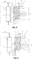
Figure 5 shows a schematic partial sectional view of a possible executive arrangement of the multilayer winding transformer according to the example shown inFigure 4 ; -
Figure 6 shows an enlarged perspective view of a portion of the transformer shown inFigure 5 . - In the following detailed description identical components have the same reference numbers, regardless of whether they are shown in different embodiments of the present invention or in different examples not being covered by the claimed invention. Furthermore, in order to clearly and concisely disclose the present invention, the drawings may not necessarily be to scale and certain features of the invention may be shown in somewhat schematic form.
- With reference to the annexed
Figures 2-6 , an electrical transformer winding arrangement is indicated with thereference number 1. The transformer provided with thewinding arrangement 1 is mainly destined to be used in high or relatively high voltage applications and in particular adopts non-uniform insulation, according to the definitions given above. - Electrical transformer comprises a core 20 and one or more winding assemblies mounted to the core 20 itself. For example, in the case of a single-phase transformer, there is only one winding assembly whilst for three-phase applications there are three winding assemblies.
- Considering the single-phase case for simplicity, the winding assembly comprises a low voltage (LV) winding 2 and a high voltage (HV) winding 3. According to the embodiments of the invention or to the examples not being covered by the claimed invention shown in the Figures, HV winding 2 and LV winding 3 are concentrically arranged around a core portion. The representations of
Figure 2 ,3, 4 and the executive view ofFigure 5 show half of thewinding arrangement 1 cross section, wherein the longitudinal axis, marked by a dotted line, corresponds to thewinding arrangement 1 cylindrical symmetry axis. Thecylindrical clearance 15 between the HV winding 3 and theLV winding 2 is commonly referred to as "main duct". - The
HV voltage winding 3 comprises a first winding section 4 and asecond winding section 5, connected together by anelectrical junction 6. First 4 and second 5 winding sections are arranged next one to the other and coaxially along direction A of the HV winding 3. With reference to the normal conditions of use of thetransformer 1, the first winding section 4 can correspond to an axially top HV winding section and thesecond winding section 5 can correspond to an axially bottom HV winding section of the HV winding 3. - The so arranged first winding section 4 and
second winding section 5, advantageously, are separated by anaxial gap 10 between said sections in the HV winding axial direction A. - The first 4 and the second 5 winding sections are of the so-called "multilayer" or "barrel" type. In particular, each of the first 4 and the second 5 winding sections comprises an electrically insulated
conductor 7 wound for example over a limb supporting the HV winding 3 itself. In each winding section theconductor 7 is wound to form a plurality oflayers 9', 9".... Thedifferent layers 9', 9"... are arranged radially, i.e. along direction R, one on top to the other. Eachlayer 9', 9"... has a predetermined number ofturns 16', 16" formed by thewounded conductor 7 in the axial direction A of the HV winding. Advantageously, the first 4 and the second 5 winding sections have the same overall number of turns (i.e. the sum of turns of all the layers). Still more advantageously, in each of the first 4 and the second 5 winding sections the total number of turns is greater than the number of the layers so to reduce the overall radial size, which in particular can be less than the radial size of a disc winding designed for the same rated voltage and current. - In general, multilayer/barrel windings require less construction time as compared to a disc winding for the same rated voltage and current.
- According to possible arrangements (see for example alternative arrangements shown in
Figures 2-3 ), in the first 4 and second 5 winding sections, the number of turns per eachlayer 9', 9" ... is the same. However, according to an alternative arrangement (see, for example, the schematic representation inFigure 4 and the corresponding executive arrangement shown schematically inFigure 5 ), in each of the first 4 and the second 5 winding sections, both the radially innermost and outermost layers have less turns than the remaining intermediate layers. The reduced number of turns at innermost and outermost layers allows to increase in the intermediate layers the electric strength by a thicker insulation of the winding edges, where the local electric field enhancement results in an increased risk of electric discharge ignition. Layers with less turns are conventionally called "graded layers". - The first winding section 4 comprises a
first terminal 11, which is located radially external, and asecond terminal 12 which is located radially internal in the first winding section 4 itself. In the same manner, thesecond winding section 5 comprises afirst terminal 13 which is located radially external and asecond terminal 14 which is located radially internal in thesecond winding section 5 itself. - The first winding section radially
external terminal 11 is normally the HV winding 3 entrance, where the electric potential is applied, and is usually connected to a line terminal of the transformer. Advantageously, the first winding section radiallyexternal terminal 11 is located axially outward with respect to the HV winding 3 itself, such that the electric strength towards grounded parts is the highest. - The second winding section radially
internal terminal 14 is normally the HV winding 3 exit, and can be connected to a transformer tap-changer or directly to a neutral terminal or to earth. The second winding section radiallyinternal terminal 14 is axially external with respect to the HV winding in a position which is axially opposite to the first winding section radiallyexternal terminal 11. In other words, referring again to the transformer normal conditions of use, the second winding section radiallyinternal terminal 14 is preferably located in an axially lower position both of thesecond winding section 5 and of the overall HV winding 3. - The first winding section radially
internal terminal 12 is joined to the second winding section radiallyexternal terminal 13 by theelectrical junction 6. The first winding section radiallyinternal terminal 12 and the second winding section radiallyexternal terminal 13 can be axially differently positioned in the respective winding section (i.e. in the axially upper or lower part of the respective section) and consequently theelectrical junction 6 can be either outside the axial gap 10 (as in the embodiment depicted inFigures 2 ) or within it (as in the examples not being covered by the claimed invention depicted inFigures 3 and 4 , as well as inFigure 5 ), as will be described hereinafter. - With reference to
Figure 2 , a winding arrangement according to a possible embodiment of the transformer is here below detailed. According to the invention, the first winding section radiallyinternal terminal 12 and the second winding section radiallyexternal terminal 13 are axially external with respect to the whole HV winding 3, and are in opposite positions. In other words, with reference to the normal conditions of use, the first winding section radiallyinternal terminal 12 and the second winding section radiallyexternal terminal 13 are respectively located in the axially upper part of the HV winding 3 (and of the first winding section 4) and in the axially lower part of the HV winding 3 (and of the second winding section 5). According to the invention, theelectrical junction 6 is located outside theaxial gap 10. - In the winding arrangement according to this embodiment, the electrical potential decays almost linearly along the
turns 16', 16"... of thelayers 9', 9", from the first section radiallyexternal terminal 11 down to the second section radiallyinternal terminal 14. This happens both in a quasi-stationary regime (at a normal power frequency, i.e. 50 or 60 Hz) and during transients (typically, lighting and switching impulses during tests and normal operation). Consequently, due to the preferred equal subdivision of the turns between the first 4 and the second 5 winding sections, in correspondence of the radially inner side of the HV winding 3, which typically faces the radially outer side of the LV winding 2, there is half of the Voltage level which is applied at the first section radiallyexternal terminal 11, which is the High Voltage winding entrance. Themain duct 15, then, can have a reduced radial dimension with respect to a disc winding designed for the same rated Voltage and Current. Therefore, in comparison to the disc winding type, the multilayer/barrel winding assembly here described can be smaller, due to the overall reduced radial dimension, and with reduced weight. - Additionally, the winding
arrangement 1 according to the above described embodiment provides a substantially constant potential difference along theaxial gap 10 between the first 4 and second 5 winding sections. Indeed, as explained above, in both the first 4 and second 5 winding sections, the electric potential with respect to ground decreases radially from the outside to the inside, at substantially the same rate. Therefore the electric potential difference between the first 4 and second 5 winding sections is fairly constant. This would not happen, for example, if the first section 4 radiallyinternal terminal 12 were connected to thesecond section 5 radiallyinternal terminal 14, and if thesecond section 5 radiallyexternal terminal 13 were connected to the earth, or to the transformer neutral terminal or to the tap changer. In this case there would be almost the total rated winding voltage across theaxial gap 10, in correspondence of the winding sections outer edges that face theaxial gap 10. - According to the invention, in the embodiment described with reference to the
Figure 2 , the number of layers of each of the first 4 and second 5 winding section is even. - In accordance with a further possible example not being covered by the claimed invention, the number of layers of each of the first 4 and second 5 winding section is odd. In this case, the first 4 and the second 5 winding sections can be differently configured and connected. Examples of this configuration are given in
Figures 3-4 . According to this example, the first section radiallyinternal terminal 12 and the second section radiallyexternal terminal 13, which are bridged together, both face the internalaxial gap 10. In this case, differently to what disclosed with reference, for example, to the embodiment shown inFigure 2 , theelectrical junction 6 can be located in theaxial gap 10. - In the configuration described above, graded layers are preferably located both in the first 4 and in the second 5 winding sections, respectively in the outermost and innermost layers, in order to decrease the electric stress located at the winding sections edges facing the axial gap 10 (see example not being covered by the claimed invention in
Figure 4 ) and in correspondence of theelectrical junction 6 between the winding sections. However, alternatively, the number of turns can be the same in each layer (see example not being covered by the claimed invention inFigure 3 ). - The executive arrangement shown in
Figure 5 corresponds to the example not being covered by the claimed invention schematically shown inFigure 4 . It is to be noted that only half of the winding arrangement, in section, is depicted, and that the dotted line represents the symmetric axis.Figure 4 shows that the radially innermost layer and the radially outermost layer of each of the first 4 and the second 5 sections have a number of turns lower than the number of turns of the intermediate layers. Moreover, theelectrical junction 6, preferably embodied by abent conductor 22, still more preferably wrapped by a convenient amount of creep paper, is located in theaxial gap 10 between the first 4 and the second 5 sections. -
Figure 6 shows an enlarged view of a portion of the HV winding 3 according to the example not being covered by the claimed invention ofFigure 5 , where theconductor 22 forming theelectrical junction 6 is located. In particular, inFigure 6 , only the second windingsection 5 is shown, whilst the first winding section is not shown. Theconductor 22 extends in theaxial gap 10 and, starting from the second section radiallyexternal terminal 13, is curved in axial direction towards the first winding section 4 (not shown inFigure 6 ), and radially towards the transformer core (not shown inFigure 6 ) since the first section radiallyinternal terminal 12 is radially internal with respect to the second section radiallyexternal terminal 13. - To the above-mentioned embodiments of the transformer with the winding arrangement according to the invention, the skilled person, in order to meet specific current needs, can make several additions, modifications, or substitutions of elements with other operatively elements, without however departing from the scope of the appended claims.
Claims (7)
- An electrical transformer comprising a core (20) and one or more winding assemblies mounted to the core, each winding assembly comprising a low voltage winding (2) and a high voltage winding (3),wherein the high voltage winding (3) comprises a first winding section (4) and a second winding section (5) arranged consecutively in the axial direction (A) of the high voltage winding (3) and connected through an electrical junction (6), the first (4) and the second (5) winding sections comprising insulated conductors (7) in multilayer arrangements wherein a plurality of conductor layers (9', 9"...), each having one or more turns (16', 16"...) in said axial direction (A), are wounded on top of one another in the radial direction (R) of the high voltage winding (3), each of the first (4) and second (5) winding sections having a radially external terminal (11, 13) and a radially internal terminal (12, 14), wherein:- the first winding section (4) radially internal terminal (12) is connected to the second winding section (5) radially external terminal (13) through said electrical junction (6);- the first winding section (4) radially external terminal (11) is the high voltage winding (3) entrance;- the second winding section (5) radially internal terminal (14) is the high voltage winding (3) exit,wherein the first winding section (4) and the second winding section (5) are arranged so to form an axial gap (10) in said axial direction (A) of the high voltage winding (3),wherein the first winding section (4) radially internal terminal (12) is axially external with respect to said high voltage winding (3) and the second winding section (5) radially external terminal (13) is axially external with respect to said high voltage winding (3), axially opposite to said first winding section (4) radially internal terminal (12),wherein said electrical junction (6) between the first (4) and the second (5) winding sections is located outside said axial gap (10),wherein the number of layers (9', 9"...) of each of said first (4) and second (5) winding section is even.
- Electrical transformer according to claim 1, wherein the high voltage winding (3) and the low voltage winding (2) are concentrically arranged.
- Electrical transformer according to claim 1 or 2, wherein said first winding section (4) and said second winding section (5) have the same number of turns (16', 16"...).
- Electrical transformer according to any of the preceding claims, wherein in each of said first (4) and second (5) winding sections the number of turns (16', 16"...) of each of said layers (9', 9") is greater than the overall number of layers.
- Electrical transformer according to any claim 1-4, wherein in each of said first (4) and second (5) winding sections each layer (9', 9"...) has the same number of turns (16', 16"...).
- Electrical transformer according to any claim 1-4, wherein in each of said first (4) and second (5) winding sections the radially innermost layer and the radially outermost layer have a number of turns (16', 16"...) lower than the number of turns (16', 16"...) of the intermediate remaining layers.
- Electrical transformer according to any of the preceding claims, wherein the first winding section (4) radially external terminal (11) is axially external with respect to said high voltage winding (3) and the second winding section (5) radially internal terminal (14) is axially external with respect to said high voltage winding (3), axially opposite to said first winding section radially external terminal (11).
Applications Claiming Priority (1)
| Application Number | Priority Date | Filing Date | Title |
|---|---|---|---|
| PCT/EP2016/050034 WO2017118472A1 (en) | 2016-01-04 | 2016-01-04 | Multilayer winding transformer |
Publications (2)
| Publication Number | Publication Date |
|---|---|
| EP3400602A1 EP3400602A1 (en) | 2018-11-14 |
| EP3400602B1 true EP3400602B1 (en) | 2021-09-01 |
Family
ID=55069881
Family Applications (1)
| Application Number | Title | Priority Date | Filing Date |
|---|---|---|---|
| EP16700012.4A Active EP3400602B1 (en) | 2016-01-04 | 2016-01-04 | Multilayer winding transformer |
Country Status (2)
| Country | Link |
|---|---|
| EP (1) | EP3400602B1 (en) |
| WO (1) | WO2017118472A1 (en) |
Families Citing this family (3)
| Publication number | Priority date | Publication date | Assignee | Title |
|---|---|---|---|---|
| DE102020123903A1 (en) * | 2020-09-14 | 2022-03-17 | Seg Automotive Germany Gmbh | Stator for an electric machine |
| WO2023088559A1 (en) * | 2021-11-18 | 2023-05-25 | Hitachi Energy Switzerland Ag | Multi-helical windings for a transformer |
| CN116525266A (en) * | 2023-06-15 | 2023-08-01 | 新昇电气有限公司 | Encapsulated transformer coil with effective filling rate and heat dissipation |
Family Cites Families (2)
| Publication number | Priority date | Publication date | Assignee | Title |
|---|---|---|---|---|
| US3675175A (en) * | 1971-05-10 | 1972-07-04 | Gen Electric | High voltage coil assembly for electric induction apparatus |
| CA1113161A (en) * | 1977-11-18 | 1981-11-24 | General Electric Company | High voltage winding for dry type transformer |
-
2016
- 2016-01-04 EP EP16700012.4A patent/EP3400602B1/en active Active
- 2016-01-04 WO PCT/EP2016/050034 patent/WO2017118472A1/en active Application Filing
Also Published As
| Publication number | Publication date |
|---|---|
| WO2017118472A1 (en) | 2017-07-13 |
| EP3400602A1 (en) | 2018-11-14 |
Similar Documents
| Publication | Publication Date | Title |
|---|---|---|
| US3528046A (en) | Interlaced disk winding with improved impulse voltage gradient | |
| BG63442B1 (en) | Dc transformer/converter | |
| EP3400602B1 (en) | Multilayer winding transformer | |
| US3466584A (en) | Winding for a stationary induction electrical apparatus | |
| US3353129A (en) | High voltage electric induction apparatus | |
| US3452311A (en) | Interleaved winding having a tapped section and switch | |
| US4017815A (en) | Impulse voltage distribution improving partial-turn electrostatic shields for disc windings | |
| US3766504A (en) | Interleaved transformer winding having three parallel connected conductors | |
| US11915856B2 (en) | Electromagnetic induction device having a low losses winding | |
| US3387243A (en) | Inductive disk winding with improved impulse voltage gradient | |
| US4270111A (en) | Electrical inductive apparatus | |
| US3569883A (en) | Electrical winding | |
| US3644786A (en) | Electrical windings | |
| US2840790A (en) | Tapped winding arrangement for variable ratio transformer | |
| US3391364A (en) | Interleaved turn, high series capacitance electrical winding structure | |
| US3391365A (en) | Interleaved winding having high series capacitance | |
| KR102561384B1 (en) | Electrical components, especially transformers or inductors | |
| US3631367A (en) | Conical layer type radial disk winding with interwound electrostatic shield | |
| JP6681323B2 (en) | Stationary induction | |
| US4047139A (en) | Transformers of large capacity for ultra-high voltages | |
| US3332050A (en) | Auto-transformer of core-form type having tapped winding disposed between axially spaced sections of high and low voltage windings | |
| JPS6236370B2 (en) | ||
| US3899764A (en) | Four-strand interleaved-turn transformer winding | |
| US8344840B2 (en) | Transformer | |
| US2874359A (en) | High voltage transformer windings with voltage control |
Legal Events
| Date | Code | Title | Description |
|---|---|---|---|
| STAA | Information on the status of an ep patent application or granted ep patent |
Free format text: STATUS: THE INTERNATIONAL PUBLICATION HAS BEEN MADE |
|
| PUAI | Public reference made under article 153(3) epc to a published international application that has entered the european phase |
Free format text: ORIGINAL CODE: 0009012 |
|
| STAA | Information on the status of an ep patent application or granted ep patent |
Free format text: STATUS: REQUEST FOR EXAMINATION WAS MADE |
|
| 17P | Request for examination filed |
Effective date: 20180702 |
|
| AK | Designated contracting states |
Kind code of ref document: A1 Designated state(s): AL AT BE BG CH CY CZ DE DK EE ES FI FR GB GR HR HU IE IS IT LI LT LU LV MC MK MT NL NO PL PT RO RS SE SI SK SM TR |
|
| AX | Request for extension of the european patent |
Extension state: BA ME |
|
| RIN1 | Information on inventor provided before grant (corrected) |
Inventor name: BUSTREO, GIANLUCA Inventor name: ZANNOL, ROBERTO Inventor name: GREGGIO, CRISTIANO Inventor name: HRKAC, MILJENKO |
|
| DAV | Request for validation of the european patent (deleted) | ||
| DAX | Request for extension of the european patent (deleted) | ||
| STAA | Information on the status of an ep patent application or granted ep patent |
Free format text: STATUS: REQUEST FOR EXAMINATION WAS MADE |
|
| RAP1 | Party data changed (applicant data changed or rights of an application transferred) |
Owner name: ABB SCHWEIZ AG |
|
| RAP1 | Party data changed (applicant data changed or rights of an application transferred) |
Owner name: ABB POWER GRIDS SWITZERLAND AG |
|
| GRAP | Despatch of communication of intention to grant a patent |
Free format text: ORIGINAL CODE: EPIDOSNIGR1 |
|
| STAA | Information on the status of an ep patent application or granted ep patent |
Free format text: STATUS: GRANT OF PATENT IS INTENDED |
|
| INTG | Intention to grant announced |
Effective date: 20210323 |
|
| GRAS | Grant fee paid |
Free format text: ORIGINAL CODE: EPIDOSNIGR3 |
|
| GRAA | (expected) grant |
Free format text: ORIGINAL CODE: 0009210 |
|
| STAA | Information on the status of an ep patent application or granted ep patent |
Free format text: STATUS: THE PATENT HAS BEEN GRANTED |
|
| AK | Designated contracting states |
Kind code of ref document: B1 Designated state(s): AL AT BE BG CH CY CZ DE DK EE ES FI FR GB GR HR HU IE IS IT LI LT LU LV MC MK MT NL NO PL PT RO RS SE SI SK SM TR |
|
| REG | Reference to a national code |
Ref country code: GB Ref legal event code: FG4D |
|
| RIN1 | Information on inventor provided before grant (corrected) |
Inventor name: ZANNOL, ROBERTO Inventor name: GREGGIO, CRISTIANO Inventor name: HRKAC, MILJENKO Inventor name: BUSTREO, GIANLUCA |
|
| REG | Reference to a national code |
Ref country code: CH Ref legal event code: EP Ref country code: AT Ref legal event code: REF Ref document number: 1427087 Country of ref document: AT Kind code of ref document: T Effective date: 20210915 |
|
| REG | Reference to a national code |
Ref country code: DE Ref legal event code: R096 Ref document number: 602016063014 Country of ref document: DE |
|
| REG | Reference to a national code |
Ref country code: IE Ref legal event code: FG4D |
|
| REG | Reference to a national code |
Ref country code: LT Ref legal event code: MG9D |
|
| REG | Reference to a national code |
Ref country code: NL Ref legal event code: FP |
|
| RAP4 | Party data changed (patent owner data changed or rights of a patent transferred) |
Owner name: HITACHI ENERGY SWITZERLAND AG |
|
| PG25 | Lapsed in a contracting state [announced via postgrant information from national office to epo] |
Ref country code: LT Free format text: LAPSE BECAUSE OF FAILURE TO SUBMIT A TRANSLATION OF THE DESCRIPTION OR TO PAY THE FEE WITHIN THE PRESCRIBED TIME-LIMIT Effective date: 20210901 Ref country code: BG Free format text: LAPSE BECAUSE OF FAILURE TO SUBMIT A TRANSLATION OF THE DESCRIPTION OR TO PAY THE FEE WITHIN THE PRESCRIBED TIME-LIMIT Effective date: 20211201 Ref country code: NO Free format text: LAPSE BECAUSE OF FAILURE TO SUBMIT A TRANSLATION OF THE DESCRIPTION OR TO PAY THE FEE WITHIN THE PRESCRIBED TIME-LIMIT Effective date: 20211201 Ref country code: FI Free format text: LAPSE BECAUSE OF FAILURE TO SUBMIT A TRANSLATION OF THE DESCRIPTION OR TO PAY THE FEE WITHIN THE PRESCRIBED TIME-LIMIT Effective date: 20210901 Ref country code: ES Free format text: LAPSE BECAUSE OF FAILURE TO SUBMIT A TRANSLATION OF THE DESCRIPTION OR TO PAY THE FEE WITHIN THE PRESCRIBED TIME-LIMIT Effective date: 20210901 Ref country code: HR Free format text: LAPSE BECAUSE OF FAILURE TO SUBMIT A TRANSLATION OF THE DESCRIPTION OR TO PAY THE FEE WITHIN THE PRESCRIBED TIME-LIMIT Effective date: 20210901 Ref country code: RS Free format text: LAPSE BECAUSE OF FAILURE TO SUBMIT A TRANSLATION OF THE DESCRIPTION OR TO PAY THE FEE WITHIN THE PRESCRIBED TIME-LIMIT Effective date: 20210901 Ref country code: SE Free format text: LAPSE BECAUSE OF FAILURE TO SUBMIT A TRANSLATION OF THE DESCRIPTION OR TO PAY THE FEE WITHIN THE PRESCRIBED TIME-LIMIT Effective date: 20210901 |
|
| REG | Reference to a national code |
Ref country code: AT Ref legal event code: MK05 Ref document number: 1427087 Country of ref document: AT Kind code of ref document: T Effective date: 20210901 |
|
| PG25 | Lapsed in a contracting state [announced via postgrant information from national office to epo] |
Ref country code: PL Free format text: LAPSE BECAUSE OF FAILURE TO SUBMIT A TRANSLATION OF THE DESCRIPTION OR TO PAY THE FEE WITHIN THE PRESCRIBED TIME-LIMIT Effective date: 20210901 Ref country code: LV Free format text: LAPSE BECAUSE OF FAILURE TO SUBMIT A TRANSLATION OF THE DESCRIPTION OR TO PAY THE FEE WITHIN THE PRESCRIBED TIME-LIMIT Effective date: 20210901 Ref country code: GR Free format text: LAPSE BECAUSE OF FAILURE TO SUBMIT A TRANSLATION OF THE DESCRIPTION OR TO PAY THE FEE WITHIN THE PRESCRIBED TIME-LIMIT Effective date: 20211202 |
|
| PG25 | Lapsed in a contracting state [announced via postgrant information from national office to epo] |
Ref country code: AT Free format text: LAPSE BECAUSE OF FAILURE TO SUBMIT A TRANSLATION OF THE DESCRIPTION OR TO PAY THE FEE WITHIN THE PRESCRIBED TIME-LIMIT Effective date: 20210901 |
|
| PG25 | Lapsed in a contracting state [announced via postgrant information from national office to epo] |
Ref country code: IS Free format text: LAPSE BECAUSE OF FAILURE TO SUBMIT A TRANSLATION OF THE DESCRIPTION OR TO PAY THE FEE WITHIN THE PRESCRIBED TIME-LIMIT Effective date: 20220101 Ref country code: SM Free format text: LAPSE BECAUSE OF FAILURE TO SUBMIT A TRANSLATION OF THE DESCRIPTION OR TO PAY THE FEE WITHIN THE PRESCRIBED TIME-LIMIT Effective date: 20210901 Ref country code: SK Free format text: LAPSE BECAUSE OF FAILURE TO SUBMIT A TRANSLATION OF THE DESCRIPTION OR TO PAY THE FEE WITHIN THE PRESCRIBED TIME-LIMIT Effective date: 20210901 Ref country code: RO Free format text: LAPSE BECAUSE OF FAILURE TO SUBMIT A TRANSLATION OF THE DESCRIPTION OR TO PAY THE FEE WITHIN THE PRESCRIBED TIME-LIMIT Effective date: 20210901 Ref country code: PT Free format text: LAPSE BECAUSE OF FAILURE TO SUBMIT A TRANSLATION OF THE DESCRIPTION OR TO PAY THE FEE WITHIN THE PRESCRIBED TIME-LIMIT Effective date: 20220103 Ref country code: EE Free format text: LAPSE BECAUSE OF FAILURE TO SUBMIT A TRANSLATION OF THE DESCRIPTION OR TO PAY THE FEE WITHIN THE PRESCRIBED TIME-LIMIT Effective date: 20210901 Ref country code: CZ Free format text: LAPSE BECAUSE OF FAILURE TO SUBMIT A TRANSLATION OF THE DESCRIPTION OR TO PAY THE FEE WITHIN THE PRESCRIBED TIME-LIMIT Effective date: 20210901 Ref country code: AL Free format text: LAPSE BECAUSE OF FAILURE TO SUBMIT A TRANSLATION OF THE DESCRIPTION OR TO PAY THE FEE WITHIN THE PRESCRIBED TIME-LIMIT Effective date: 20210901 |
|
| REG | Reference to a national code |
Ref country code: DE Ref legal event code: R097 Ref document number: 602016063014 Country of ref document: DE |
|
| REG | Reference to a national code |
Ref country code: DE Ref legal event code: R081 Ref document number: 602016063014 Country of ref document: DE Owner name: HITACHI ENERGY SWITZERLAND AG, CH Free format text: FORMER OWNER: ABB POWER GRIDS SWITZERLAND AG, BADEN, CH Ref country code: DE Ref legal event code: R081 Ref document number: 602016063014 Country of ref document: DE Owner name: HITACHI ENERGY LTD, CH Free format text: FORMER OWNER: ABB POWER GRIDS SWITZERLAND AG, BADEN, CH |
|
| PLBE | No opposition filed within time limit |
Free format text: ORIGINAL CODE: 0009261 |
|
| STAA | Information on the status of an ep patent application or granted ep patent |
Free format text: STATUS: NO OPPOSITION FILED WITHIN TIME LIMIT |
|
| PG25 | Lapsed in a contracting state [announced via postgrant information from national office to epo] |
Ref country code: DK Free format text: LAPSE BECAUSE OF FAILURE TO SUBMIT A TRANSLATION OF THE DESCRIPTION OR TO PAY THE FEE WITHIN THE PRESCRIBED TIME-LIMIT Effective date: 20210901 |
|
| 26N | No opposition filed |
Effective date: 20220602 |
|
| PG25 | Lapsed in a contracting state [announced via postgrant information from national office to epo] |
Ref country code: SI Free format text: LAPSE BECAUSE OF FAILURE TO SUBMIT A TRANSLATION OF THE DESCRIPTION OR TO PAY THE FEE WITHIN THE PRESCRIBED TIME-LIMIT Effective date: 20210901 Ref country code: MC Free format text: LAPSE BECAUSE OF FAILURE TO SUBMIT A TRANSLATION OF THE DESCRIPTION OR TO PAY THE FEE WITHIN THE PRESCRIBED TIME-LIMIT Effective date: 20210901 |
|
| REG | Reference to a national code |
Ref country code: CH Ref legal event code: PL |
|
| REG | Reference to a national code |
Ref country code: BE Ref legal event code: MM Effective date: 20220131 |
|
| PG25 | Lapsed in a contracting state [announced via postgrant information from national office to epo] |
Ref country code: LU Free format text: LAPSE BECAUSE OF NON-PAYMENT OF DUE FEES Effective date: 20220104 |
|
| PG25 | Lapsed in a contracting state [announced via postgrant information from national office to epo] |
Ref country code: BE Free format text: LAPSE BECAUSE OF NON-PAYMENT OF DUE FEES Effective date: 20220131 |
|
| PG25 | Lapsed in a contracting state [announced via postgrant information from national office to epo] |
Ref country code: LI Free format text: LAPSE BECAUSE OF NON-PAYMENT OF DUE FEES Effective date: 20220131 Ref country code: CH Free format text: LAPSE BECAUSE OF NON-PAYMENT OF DUE FEES Effective date: 20220131 |
|
| PG25 | Lapsed in a contracting state [announced via postgrant information from national office to epo] |
Ref country code: IE Free format text: LAPSE BECAUSE OF NON-PAYMENT OF DUE FEES Effective date: 20220104 |
|
| REG | Reference to a national code |
Ref country code: NL Ref legal event code: HC Owner name: HITACHI ENERGY SWITZERLAND AG; CH Free format text: DETAILS ASSIGNMENT: CHANGE OF OWNER(S), CHANGE OF OWNER(S) NAME; FORMER OWNER NAME: ABB POWER GRIDS SWITZERLAND AG Effective date: 20230209 |
|
| PGFP | Annual fee paid to national office [announced via postgrant information from national office to epo] |
Ref country code: FR Payment date: 20230124 Year of fee payment: 8 |
|
| PGFP | Annual fee paid to national office [announced via postgrant information from national office to epo] |
Ref country code: TR Payment date: 20230102 Year of fee payment: 8 Ref country code: IT Payment date: 20230120 Year of fee payment: 8 Ref country code: GB Payment date: 20230119 Year of fee payment: 8 Ref country code: DE Payment date: 20230123 Year of fee payment: 8 |
|
| PGFP | Annual fee paid to national office [announced via postgrant information from national office to epo] |
Ref country code: NL Payment date: 20230119 Year of fee payment: 8 |
|
| P01 | Opt-out of the competence of the unified patent court (upc) registered |
Effective date: 20230527 |
|
| PGFP | Annual fee paid to national office [announced via postgrant information from national office to epo] |
Ref country code: NL Payment date: 20240119 Year of fee payment: 9 |
|
| PG25 | Lapsed in a contracting state [announced via postgrant information from national office to epo] |
Ref country code: HU Free format text: LAPSE BECAUSE OF FAILURE TO SUBMIT A TRANSLATION OF THE DESCRIPTION OR TO PAY THE FEE WITHIN THE PRESCRIBED TIME-LIMIT; INVALID AB INITIO Effective date: 20160104 |
|
| REG | Reference to a national code |
Ref country code: DE Ref legal event code: R082 Ref document number: 602016063014 Country of ref document: DE Representative=s name: DENNEMEYER & ASSOCIATES S.A., DE Ref country code: DE Ref legal event code: R081 Ref document number: 602016063014 Country of ref document: DE Owner name: HITACHI ENERGY LTD, CH Free format text: FORMER OWNER: HITACHI ENERGY SWITZERLAND AG, BADEN, CH |
|
| REG | Reference to a national code |
Ref country code: NL Ref legal event code: PD Owner name: HITACHI ENERGY LTD; CH Free format text: DETAILS ASSIGNMENT: CHANGE OF OWNER(S), MERGE; FORMER OWNER NAME: HITACHI ENERGY SWITZERLAND AG Effective date: 20240403 |