EP3400405B1 - Automatisches beleuchtungs- und sicherheitssystem - Google Patents
Automatisches beleuchtungs- und sicherheitssystem Download PDFInfo
- Publication number
- EP3400405B1 EP3400405B1 EP17700048.6A EP17700048A EP3400405B1 EP 3400405 B1 EP3400405 B1 EP 3400405B1 EP 17700048 A EP17700048 A EP 17700048A EP 3400405 B1 EP3400405 B1 EP 3400405B1
- Authority
- EP
- European Patent Office
- Prior art keywords
- visible light
- interest
- light source
- axis
- infrared light
- Prior art date
- Legal status (The legal status is an assumption and is not a legal conclusion. Google has not performed a legal analysis and makes no representation as to the accuracy of the status listed.)
- Active
Links
Images


Classifications
-
- H—ELECTRICITY
- H05—ELECTRIC TECHNIQUES NOT OTHERWISE PROVIDED FOR
- H05B—ELECTRIC HEATING; ELECTRIC LIGHT SOURCES NOT OTHERWISE PROVIDED FOR; CIRCUIT ARRANGEMENTS FOR ELECTRIC LIGHT SOURCES, IN GENERAL
- H05B47/00—Circuit arrangements for operating light sources in general, i.e. where the type of light source is not relevant
- H05B47/10—Controlling the light source
- H05B47/105—Controlling the light source in response to determined parameters
- H05B47/115—Controlling the light source in response to determined parameters by determining the presence or movement of objects or living beings
- H05B47/125—Controlling the light source in response to determined parameters by determining the presence or movement of objects or living beings by using cameras
-
- F—MECHANICAL ENGINEERING; LIGHTING; HEATING; WEAPONS; BLASTING
- F21—LIGHTING
- F21V—FUNCTIONAL FEATURES OR DETAILS OF LIGHTING DEVICES OR SYSTEMS THEREOF; STRUCTURAL COMBINATIONS OF LIGHTING DEVICES WITH OTHER ARTICLES, NOT OTHERWISE PROVIDED FOR
- F21V23/00—Arrangement of electric circuit elements in or on lighting devices
- F21V23/04—Arrangement of electric circuit elements in or on lighting devices the elements being switches
- F21V23/0442—Arrangement of electric circuit elements in or on lighting devices the elements being switches activated by means of a sensor, e.g. motion or photodetectors
- F21V23/0471—Arrangement of electric circuit elements in or on lighting devices the elements being switches activated by means of a sensor, e.g. motion or photodetectors the sensor detecting the proximity, the presence or the movement of an object or a person
- F21V23/0478—Arrangement of electric circuit elements in or on lighting devices the elements being switches activated by means of a sensor, e.g. motion or photodetectors the sensor detecting the proximity, the presence or the movement of an object or a person by means of an image recording device, e.g. a camera
-
- G—PHYSICS
- G06—COMPUTING OR CALCULATING; COUNTING
- G06F—ELECTRIC DIGITAL DATA PROCESSING
- G06F18/00—Pattern recognition
- G06F18/20—Analysing
- G06F18/22—Matching criteria, e.g. proximity measures
-
- G—PHYSICS
- G06—COMPUTING OR CALCULATING; COUNTING
- G06F—ELECTRIC DIGITAL DATA PROCESSING
- G06F18/00—Pattern recognition
- G06F18/20—Analysing
- G06F18/24—Classification techniques
- G06F18/243—Classification techniques relating to the number of classes
- G06F18/2431—Multiple classes
-
- G—PHYSICS
- G06—COMPUTING OR CALCULATING; COUNTING
- G06T—IMAGE DATA PROCESSING OR GENERATION, IN GENERAL
- G06T7/00—Image analysis
- G06T7/20—Analysis of motion
- G06T7/246—Analysis of motion using feature-based methods, e.g. the tracking of corners or segments
-
- G—PHYSICS
- G06—COMPUTING OR CALCULATING; COUNTING
- G06V—IMAGE OR VIDEO RECOGNITION OR UNDERSTANDING
- G06V10/00—Arrangements for image or video recognition or understanding
- G06V10/10—Image acquisition
- G06V10/12—Details of acquisition arrangements; Constructional details thereof
- G06V10/14—Optical characteristics of the device performing the acquisition or on the illumination arrangements
- G06V10/143—Sensing or illuminating at different wavelengths
-
- G—PHYSICS
- G06—COMPUTING OR CALCULATING; COUNTING
- G06V—IMAGE OR VIDEO RECOGNITION OR UNDERSTANDING
- G06V10/00—Arrangements for image or video recognition or understanding
- G06V10/20—Image preprocessing
- G06V10/25—Determination of region of interest [ROI] or a volume of interest [VOI]
-
- G—PHYSICS
- G06—COMPUTING OR CALCULATING; COUNTING
- G06V—IMAGE OR VIDEO RECOGNITION OR UNDERSTANDING
- G06V20/00—Scenes; Scene-specific elements
- G06V20/50—Context or environment of the image
- G06V20/52—Surveillance or monitoring of activities, e.g. for recognising suspicious objects
-
- G—PHYSICS
- G06—COMPUTING OR CALCULATING; COUNTING
- G06V—IMAGE OR VIDEO RECOGNITION OR UNDERSTANDING
- G06V20/00—Scenes; Scene-specific elements
- G06V20/50—Context or environment of the image
- G06V20/56—Context or environment of the image exterior to a vehicle by using sensors mounted on the vehicle
-
- G—PHYSICS
- G08—SIGNALLING
- G08B—SIGNALLING SYSTEMS, e.g. PERSONAL CALLING SYSTEMS; ORDER TELEGRAPHS; ALARM SYSTEMS
- G08B13/00—Burglar, theft or intruder alarms
- G08B13/18—Actuation by interference with heat, light, or radiation of shorter wavelength; Actuation by intruding sources of heat, light, or radiation of shorter wavelength
- G08B13/189—Actuation by interference with heat, light, or radiation of shorter wavelength; Actuation by intruding sources of heat, light, or radiation of shorter wavelength using passive radiation detection systems
- G08B13/194—Actuation by interference with heat, light, or radiation of shorter wavelength; Actuation by intruding sources of heat, light, or radiation of shorter wavelength using passive radiation detection systems using image scanning and comparing systems
- G08B13/196—Actuation by interference with heat, light, or radiation of shorter wavelength; Actuation by intruding sources of heat, light, or radiation of shorter wavelength using passive radiation detection systems using image scanning and comparing systems using television cameras
- G08B13/19602—Image analysis to detect motion of the intruder, e.g. by frame subtraction
- G08B13/19606—Discriminating between target movement or movement in an area of interest and other non-signicative movements, e.g. target movements induced by camera shake or movements of pets, falling leaves, rotating fan
-
- H—ELECTRICITY
- H04—ELECTRIC COMMUNICATION TECHNIQUE
- H04N—PICTORIAL COMMUNICATION, e.g. TELEVISION
- H04N23/00—Cameras or camera modules comprising electronic image sensors; Control thereof
- H04N23/56—Cameras or camera modules comprising electronic image sensors; Control thereof provided with illuminating means
-
- H—ELECTRICITY
- H04—ELECTRIC COMMUNICATION TECHNIQUE
- H04N—PICTORIAL COMMUNICATION, e.g. TELEVISION
- H04N7/00—Television systems
- H04N7/18—Closed-circuit television [CCTV] systems, i.e. systems in which the video signal is not broadcast
- H04N7/183—Closed-circuit television [CCTV] systems, i.e. systems in which the video signal is not broadcast for receiving images from a single remote source
-
- G—PHYSICS
- G06—COMPUTING OR CALCULATING; COUNTING
- G06T—IMAGE DATA PROCESSING OR GENERATION, IN GENERAL
- G06T2207/00—Indexing scheme for image analysis or image enhancement
- G06T2207/10—Image acquisition modality
- G06T2207/10048—Infrared image
-
- G—PHYSICS
- G06—COMPUTING OR CALCULATING; COUNTING
- G06T—IMAGE DATA PROCESSING OR GENERATION, IN GENERAL
- G06T2207/00—Indexing scheme for image analysis or image enhancement
- G06T2207/20—Special algorithmic details
- G06T2207/20084—Artificial neural networks [ANN]
-
- G—PHYSICS
- G06—COMPUTING OR CALCULATING; COUNTING
- G06T—IMAGE DATA PROCESSING OR GENERATION, IN GENERAL
- G06T2207/00—Indexing scheme for image analysis or image enhancement
- G06T2207/30—Subject of image; Context of image processing
- G06T2207/30232—Surveillance
-
- Y—GENERAL TAGGING OF NEW TECHNOLOGICAL DEVELOPMENTS; GENERAL TAGGING OF CROSS-SECTIONAL TECHNOLOGIES SPANNING OVER SEVERAL SECTIONS OF THE IPC; TECHNICAL SUBJECTS COVERED BY FORMER USPC CROSS-REFERENCE ART COLLECTIONS [XRACs] AND DIGESTS
- Y02—TECHNOLOGIES OR APPLICATIONS FOR MITIGATION OR ADAPTATION AGAINST CLIMATE CHANGE
- Y02B—CLIMATE CHANGE MITIGATION TECHNOLOGIES RELATED TO BUILDINGS, e.g. HOUSING, HOUSE APPLIANCES OR RELATED END-USER APPLICATIONS
- Y02B20/00—Energy efficient lighting technologies, e.g. halogen lamps or gas discharge lamps
- Y02B20/40—Control techniques providing energy savings, e.g. smart controller or presence detection
Definitions
- the technical field of the invention is that of automatic lighting, and in particular that of the automatic lighting of an outside environment.
- the present invention relates to an automatic lighting device.
- an automatic lighting device comprising a motion detector.
- the motion detector typically uses an infrared technology.
- the device activates lighting.
- the device deactivates the lighting.
- Such a device does however present the drawback of not making any distinction between different categories of objects.
- the lighting is thus triggered as soon as a motion is detected, whether it is for example the motion of a pedestrian, of an animal, or of a vehicle. This creates unnecessary light pollution.
- the invention discloses a device comprising an image sensor, an IR light source, a visible light source and a processing unit configured to detect moving foreground elements of a scene, to track them and to classify them into different types of objects of interest that may trigger or not the illumination of the scene by the visible light source or an alarm.
- the device of the invention also brings improved security to the location where it is installed.
- it may be controlled remotely, possibly through the internet.
- the environment is lit with infrared light, in a range of wavelengths invisible to the human eye.
- the camera picks up an infrared light reflected by the environment and produces at least one image of the environment from the infrared light reflected by the environment.
- the processing unit assigns, to at least a part of this image, at least one class out of a plurality of classes.
- one or more classes can be assigned to the entire image or to a part of the image.
- the control unit activates the visible light source as a function of the class assigned to each area of interest detected. A user can thus advantageously chose one or more classes for which he or she wants the lighting with visible light to be activated. The lighting with visible light remains deactivated for all the classes that the user has not chosen.
- the plurality of classes typically comprises:
- the automatic lighting device can have one or more additional features out of the following, considered individually or in all technically possible combinations:
- a first image of the film, filmed at a time t1, and a second image of the film, filmed at a time t2 later than the time t1, are "immediately consecutive" if there is no image of the film filmed at a time t such that t1 ⁇ t ⁇ t2.
- a thumbnail image extracted from an image can have pixel dimensions less than or equal to the pixel dimensions of the image from which it is extracted.
- One and the same area of interest which moves in the field of the camera appears on a plurality of k immediately consecutive images. For each image of the plurality of images, a thumbnail image is then defined which contains said area of interest. A plurality of N thumbnail images is obtained.
- the tracking of such an area of interest advantageously makes it possible to associate the plurality of N thumbnail images with said single area of interest. Detecting N areas of interest with a single thumbnail image associated with each of the N areas of interest is thus avoided.
- Choosing a subset of p thumbnail images out of the plurality of N thumbnail images of said area of interest also makes it possible to improve the accuracy of the classification algorithm, by providing the classification algorithm with an input datum of good quality.
- the subset of p thumbnail images can in fact be chosen, from the plurality of N thumbnail images, for its intrinsic qualities. In a complementary or alternative manner, the subset of p thumbnail images can be processed in order to improve the properties thereof.
- the step of detection, for each pair of immediately consecutive images of the film, of at least one area of interest exhibiting a motion comprises:
- the motion of a cloud and the motion of a tree branch stirred by the wind belong, for example, to the first type of motions.
- Each thumbnail image of the set of k thumbnail images of each area of interest detected can be defined as being the smallest rectangle containing said area of interest detected. The size of each thumbnail image is thus minimized, which makes it possible to reduce the computation time linked to the operation of the classification algorithm.
- each thumbnail image of the set of k thumbnail images of each area of interest detected can be defined as being the smallest ellipse containing said area of interest detected, or as being the smallest polygon containing said area of interest detected.
- the dimensions of a thumbnail image can vary from one area of interest to another. The dimensions of a thumbnail image can also vary during the tracking of one and the same area of interest.
- the choice of the single thumbnail image out of the set of k thumbnail images is advantageously made as a function of a type of movement of said area of interest.
- the device advantageously has a first mode of operation according to which the choice of the single thumbnail image is made from a subset of the set of k thumbnail images, the subset comprising the q first images of the set of k thumbnail images, with q being a natural integer less than or equal to 10, and preferentially less than or equal to 5.
- q being a natural integer less than or equal to 10, and preferentially less than or equal to 5.
- the camera comprising a lens and an infrared light and visible light sensor, the at least one infrared light source having a cone of emission of infrared light, and the at least one visible light source having a cone of emission of visible light, the device is advantageously such that there is no intersection between the lens of the camera on the one hand and the cones of emission of infrared light and of visible light on the other hand.
- the lens having an axis of revolution A and comprising a first face having a normal vector oriented towards the sensor and a second face having a normal vector oriented towards the environment, and a first plane tangential to the first face and at right angles to the axis of revolution A defining a first half-space to which the sensor belongs and a second half-space to which the second face of the lens and the environment belong, the device is advantageously such that:
- the device advantageously comprises a protection element for the at least one infrared light source, for the at least one visible light source and for the lens of the camera, the protection element being transparent to the infrared light and to the visible light, the protection element extending substantially along a plane at right angles to the axis of revolution A.
- the device is thus made seal-tight, for use in an outside environment regardless of weather conditions. The integrity of the settings of the device in case of manipulation by a user is also guaranteed. Finally, the user manipulating the device is protected from any burns due to the infrared and visible light sources.
- the at least one infrared light source having a cone of emission of axis A40, the at least one visible light source having a cone of emission of axis A50, and the camera having a cone of absorption of axis A is advantageously such that:
- the device advantageously comprises a plurality of visible light sources, each visible light source having a cone of emission having an axis.
- the distance between the axis of the cone of emission of said source and the axis of the cone of emission of each other source is advantageously constant or increasing when moving away from the first plane.
- a region is thus obtained, in the second half-space, in which at least two cones of emission of visible light overlap.
- the uniformity of the lighting with visible light is thus improved, notably by eliminating any central halo.
- the device advantageously comprises a plurality of infrared light sources, each infrared light source having a cone of emission having an axis.
- the distance between the axis of the cone of emission of said source and the axis of the cone of emission of each other source is advantageously constant or increasing when moving away from the first plane.
- a region is thus obtained, in the second half-space, in which at least two cones of emission of infrared light overlap.
- the uniformity of the lighting with infrared light is thus improved, notably by eliminating any central halo.
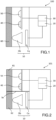
- FIG. 1 shows a schematic representation of an automatic lighting device 100 helpful for the understanding embodiments.
- the device 100 comprises:
- “Visible light” is typically understood to mean a light visible to a human user, that is to say a light whose wavelength belongs substantially to the range [380 nm; 780 nm].
- “Infrared light” is typically understood to mean a light invisible to a human user and whose wavelength is greater than 780 nm.
- the infrared light source can be a light-emitting diode, or LED.
- the visible light source can be an LED, or, alternatively, a halogen lamp or a neon lamp, etc.
- the visible light source, the infrared light source and the camera can be combined in a single module, as represented in Figure 1 .
- the visible light source can be located in a first module, whereas the infrared light source and the camera are combined in a second module distinct from the first module.
- the visible light source can be located in a first module, the infrared light source can be located in a second module distinct from the first module, and the camera can be located in a third module distinct from the first and second modules.
- the infrared light source 40 is activated permanently.
- the infrared light source 40 can be deactivated.
- the first mode of operation is, for example, activated during the night.
- the second mode of operation is, for example, activated during the day.
- an environment is thus lit with infrared light at each instant.
- the camera 10 can then film an environment lit with infrared light.
- Each image filmed by the camera 10 is typically obtained by virtue of the infrared light reflected by the environment and arriving at the sensor Ca.
- the sensor Ca of the camera 10 is, for example, a CMOS sensor.
- the processing unit 20 can, for example, be a microcontroller or a microprocessor.
- the control unit 30 can, for example, be a microcontroller or a microprocessor.
- a single microcontroller or microprocessor can simultaneously comprise the processing unit 20 and the control unit 30.
- the protection element 60 seals the device 100 and thus allows for its use in an outside environment, while being transparent to the infrared light and to the visible light.
- FIG. 2 shows a second schematic representation of an automatic lighting device 101 helpful for the understanding embodiments.
- the device 101 according to the second schematic representation comprises a separation element Se, which separates the infrared light source 40 and the visible light source 50 on the one hand, and the camera 10 on the other hand.
- the separation element Se makes it possible to prevent a radiation from the infrared light source 40 and/or a radiation from the visible light source 50 from reaching the sensor Ca of the camera 10.
- the protection element 60 is split up into a first part 61 for the protection of the infrared light source 40 and of the visible light source 50, and a second part 62 for the protection of the camera 10.
- FIG 3 shows a third schematic representation of an automatic lighting device 102 helpful for the understanding embodiments.
- the device 102 according to the third schematic representation comprises an infrared filter fIR.
- the infrared filter fIR can typically be arranged in a first position or in a second position, which are respectively illustrated in connection with Figures 4a and 4b .
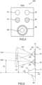
- Figure 4a shows a first cross-sectional view of the device 102 according to the third schematic representation.
- Figure 4a shows the infrared filter fIR arranged in the first position. In the first position, the infrared filter fIR is separated from the sensor Ca so that the infrared light can penetrate into the sensor Ca.
- Figure 4b shows a second cross-sectional view of the device 102 according to the third schematic representation.
- Figure 4b shows the infrared filter fIR arranged in the second position. In the second position, the infrared filter fIR is placed between the lens Ob and the sensor Ca of the camera 10 in order to prevent the infrared light from penetrating into the sensor Ca.
- the automatic lighting device 102 can advantageously operate at any time of the day or of the night: the infrared filter fIR is placed in its first position during the night, and in its second position during the day. It is in fact desirable to cut the infrared light emitted by the sun during the day, in order to improve the rendering of the images picked up by the camera 10, for a human user.
- Figure 5 shows a cross-sectional view of an automatic lighting device 102' according to a variant of the third schematic representation.
- the automatic lighting device 102' comprises a plurality of infrared light sources and a plurality of visible light sources.
- the plurality of infrared light sources comprises the infrared light source 40 and a second infrared light source 41.
- the plurality of infrared light sources can comprise three or more infrared light sources.
- the plurality of visible light sources comprises the visible light source 50 and a second visible light source 51.
- the plurality of visible light sources can comprise three or more visible light sources.
- the automatic lighting device can comprise a single infrared light source and a plurality of visible light sources.
- the automatic lighting device can comprise a plurality of infrared light sources and a single visible light source.
- the automatic lighting device advantageously comprises an accelerometer.
- a motion of the automatic lighting device can thus be detected, in order to avoid, if necessary, an incorrect detection of a motion within the environment observed.
- the automatic lighting device advantageously comprises a communication interface making it possible to receive signals from at least one mobile terminal, and transmit signals to at least one mobile terminal.
- the communication interface can, for example, be a radiofrequency interface, or a Wi-Fi interface, or a Bluetooth interface, or a Zigbee interface, etc.
- FIG. 6 shows a schematic representation of the arrangement of the lens Ob, of the visible light source 50 and of the infrared light source 40 of an automatic lighting device helpful for the understanding embodiments.
- the lens Ob which has an axis of revolution A, comprises:
- a first plane P1 tangential to the first face f1 and at right angles to the axis of revolution A of the lens Ob, defines:
- the visible light source 50 is advantageously arranged such that the vertex s50 of the cone of emission c50 is located in the second half-space dE2.
- the infrared light source 40 is advantageously arranged such that the vertex s40 of the cone of emission c40 is located in the second half-space dE2.
- the automatic lighting device preferentially comprises the protection element 60.
- the radiation emitted by the infrared light source 40 is likely to be partially reflected by the protection element 60.
- the infrared light source 40 is advantageously arranged such that, in the second half-space dE2, the distance between the axis A40 of the infrared light source 40 and the axis of revolution A of the lens Ob is constant or increasing when moving away from the first plane P1.
- Figure 6 shows, for example:
- the second distance D2 is greater than or equal to the first distance D1.
- the visible light source 50 is advantageously arranged such that, in the second half-space dE2, the distance between the axis A50 of the visible light source 50 and the axis of revolution A of the lens Ob is constant or increasing when moving away from the first plane P1.
- the automatic lighting device comprises a plurality of visible light sources, each visible light source having a cone of emission, said plurality is preferentially arranged so as to obtain, in the second half-space dE2, a region in which at least two cones of emission of visible light overlap.
- the automatic lighting device comprises as plurality of infrared light sources, each infrared light source having a cone of emission, said plurality is preferentially arranged so as to obtain, in the second half-space dE2, a region in which at least two cones of emission of infrared light overlap.
- Figure 7 shows a schematic representation of the arrangement of the visible light sources of an automatic lighting device comprising a plurality of visible light sources.
- the device of Figure 7 comprises:
- the visible light source 50 and the second visible light source 51 are advantageously arranged so that, in the first half-space dE1, the distance between the axis A50 of the visible light source 50 and the axis A51 of the second visible light source 51 is constant or increasing when moving away from the first plane P1.
- Figure 7 shows, for example:
- the fourth distance D4 is greater than or equal to the third distance D3.
- the arrangement illustrated in Figure 7 for a plurality of visible light sources can be transposed to a plurality of infrared light sources.
- Figure 8 shows a schematic representation of a processing of an image Im by the processing unit 20 of an automatic lighting.
- the processing unit 20 detects first, second and third areas of interest z1, z2 and z3 in the image Im.
- the first area of interest z1 is, for example, a pedestrian in motion.
- the second area of interest z2 is, for example, a vehicle in motion.
- the third area of interest z3 is, for example, an animal in motion.
- the processing unit 20 defines a first thumbnail image v1 for the first area of interest z1, a second thumbnail image v2 for the second area of interest z2 and a third thumbnail image v3 for the third area of interest z3.
- the processing unit 20 assigns, to each area of interest, a class out of a plurality of classes.
- the plurality of classes comprises:
- control unit 30 can activate the visible light source as soon as the first class is assigned to at least one thumbnail image.
- the first category is, for example, that of pedestrians.
- the first category can be that of animals or of vehicles.
- the processing unit 20 assigns the first class to the first thumbnail image v1, and the second class to the second and third thumbnail images v2 and v3.
- the plurality of classes comprises:
- the control unit 30 can activate the visible light source as soon as the first class is assigned to at least one thumbnail image or as soon as the second class is assigned to at least one thumbnail image.
- the plurality of classes comprises:
- the control unit 30 can activate the visible light source as soon as the first class is assigned to at least one thumbnail image or as soon as the second class is assigned to at least one thumbnail image or as soon as the third class is assigned to at least one thumbnail image.
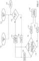
- Figure 9 displays a flow chart of an identification method using an image sensor helpful for the understanding of certain embodiments.
- the lighting device 100 comprises a processing unit 20 that is configured to determine an object of interest that will trigger one or more actions.
- One of the actions is to set through a control unit 30 one or more sources 50, 51 of visible light ON or to leave it in an OFF state depending upon a type of the object of interest that is lighted by one or more infrared (IR) light sources 40, 41 and detected by an image sensor 10.
- Another possible action is to trigger an alarm that may be generated locally or sent to a remote location.
- the owner of the property where the device is installed or a watchman tasked with monitoring the property may then take appropriate action, based notably on the images captured by the image sensor 10 that may be sent to the owner or the watchman on a device using a communication link.
- the processing unit 20 comprises processing logic that may be embedded in the hardware of the lighting device or stored in a memory connected to the processing unit to determine if an event occurring in the field of view of the image sensor should or not trigger a command or an alarm.
- the processing logic is configured to minimize the number of false alarms, maximize the number of true detection of alarming events and minimize the processing power used.
- a processing architecture implements three successive processing steps of image analysis:
- Image analysis is a field of computer technology that is used to extract meaningful information from images.
- it is applied to a scene surrounding a building that comprises Regions of Interest (Rol), i.e. regions where moving objects are detected and then classified into types of Objects of Interest (Ool) that are present in the scene.
- Rol Regions of Interest
- Ool Objects of Interest
- the output of the classifying step 930 that comprise probabilities of an object being an Object of Interest (Ool) of a predefined type (human, animal, car, etc8) may be further processed to de-duplicate the Ool to check if they have already been seen earlier.
- the probabilities that an Ool belongs to one of a defined class are passed (step 931) to a de-duplication step 932. If the Ool has been seen before, the Ool is discarded and no action (setting the light source ON, triggering an alarm or sending a notification) is taken and the Ool is ignored (step 933).
- step 940 If the Ool has not been seen in a recent sequence of frames, one or more of the actions of setting the light source ON, triggering an alarm or notifying a user are performed (step 940).
- the time that is taken into account to determine that the Ool has been seen before is a matter of seconds. It may be user defined, or it may be defined by the memory allocation to this function in the device.
- the appropriate command or alarm may be triggered with minimal false alarms and maximal true positives, having used a processing power that is consistent with the capacity of the processing unit in a time that is consistent with the use case.
- steps 910, 920 and 930 are described in detail further below respectively in relation with figures 10 , 11 and 12 .
- the classes or types of the objects of interest may for instance be: humans; animals; cars. But other classes may be added. Or only one class or two classes may be selected to trigger setting the lights ON or triggering an alarm.
- Figure 10 displays a flow chart of a detection method of regions of interest in a scene according to some embodiments of the invention.
- the purpose of the step of detection of regions of interest in a scene is to differentiate in a series of images of a scene a moving foreground, that will include the regions of interest, from a still background.
- the method consists in first modeling the background of the scene to provide an image of reference. Then, a comparison between the running image and the image of reference (i.e. background subtraction or foreground extraction) yields pixels labeled as "in movement".
- a designer of a method to efficiently perform this step will encounter a number of difficulties, notably:
- BM Background Model
- BM is constructed from a number of frames preceding the current image frame that are stored in a FIFO ("First In First Out") memory.
- the size n of the used pixels in the FIFO should be small enough to avoid an impact of reasonably slow illumination changes and large enough to include parts of the scene that are not normally moving and should be considered as background.
- the inventors have determined experimentally that a duration of a few seconds (or 50 to 250 frames at 24 fps - i.e. frames per second) is a good compromise. Note that the Y luminance data in a YUV encoding by the image sensor processing is sufficient to extract information from a series of images of a scene to construct the BM.
- An efficient BM may be built by making the assumption that pixels that take the luminance value of the median of the buffer belong to the background. But calculating a median of a series that varies over time is computationally complex. This is why, in a variant, the inventors use a rolling average of the series of pixel luminance values in the buffer.
- a number of selections of the pixels in the buffer may be made: either the p most recent corresponding pixels in the buffer or the p oldest pixels in the buffer, where p is the number of pixels selected to correspond to the number n of pixels in the FIFO determined to be optimal as explained above. It has been determined experimentally by the inventors that it is advantageous to select the option that yields the mean that is the closest to the current BM.
- a motion image is constructed by setting the luminance value of a pixel in a frame to 1 when the subtraction of the luminance of the corresponding pixel of the BM frame from the corresponding pixel in the input frame (that may be a preprocessed frame 1020, in case a cleansing of the frames is performed, i.e. to suppress noise as explained below) is higher than a calculated luminance of a corresponding pixel in a Threshold Image of the frame (TI), and setting this luminance value to 0 when this condition is not met.
- TI Threshold Image of the frame
- a dynamic Threshold Image TI
- TI Threshold Image
- the heuristic is based on two considerations:
- the inventors have determined that setting the parameters ⁇ and ⁇ respectively at 30 and 3 will decrease the false negative rate in shaded areas without increasing the false positive rate in bright areas, but other values are possible.
- both the BM and the current frame may be blurred (i.e. their contrast diminished) through a preprocessing step (1020) to reduce the impact of noise.
- the thresholding 1050 is the result of an extraction of the images such that:
- a Background Cleaning may be performed (1070) by subtracting from the current frame the First Foreground frame. This yields a Modified Background BM' (1080) with which a second thresholding may be performed (1090) to yield a Second Foreground frame (10A0).
- a post-processing of the Second Foreground frame 10A0 may be performed at a step 10B0.
- One of the goals of this step will be to eliminate parts of the image that may be noise and that are anyway too small to be properly classified.
- We can for instance determine the minimum size in pixel that is necessary to detect a person of 1,6 m height using opto-geometrical relationships such as: h m HW 2 tan ⁇ ⁇ D M where:
- the minim size of objects of 1,6 m height that will be detectable with the sensor from 20 m is about 100 pixels.
- Combining minimum height and width allows defining a structuring element or Bounding Box (BB). Objects in the foreground of a size lower than BB but close enough will be grouped, whereas those of also a size lower than BB but isolated will be filtered out.
- BB Bounding Box
- the output of the detection process is a set of BB vectors 10C0 that are passed to the tracking process.
- the detection process of the invention is remarkable notably in that it considers only the grey levels of the image pixels and compensates for the "ghosting" effect in calculating a shifted variance.
- Figure 11 displays a flow chart of a tracking method of regions of interest that have been detected in a scene according to some embodiments of the invention.
- the detection process described above notably presents the advantage of allowing loosing some BBs. Accordingly, the tracking may be simpler than those of the prior art.
- the tracking process of the invention is derived from a method described in Bouguet ("Pyramidal Implementation of the Lucas Kanade Feature Tracker", Intel Corp. Microprocessor Research Labs, 2000 ). This process builds on Lucas and Kanade, "An Iterative Image Registration Technique with an Application to Stereo Vision", Proceedings of the 7th International Joint Conference on Artificial Intelligence, Vol. 2, IJCAI'81, pp. 674-679, 1981 , and on Tomasi and Shi, "Good Features to Track", 1994 I3E Conference on Computer Vision and Pattern Recognition, CVPR'94, pp. 593-600, 1994 .
- detected BBs are compared with existing trackers' locations, leading to the creation of new trackers when a comparable tracker is not yet present in the plurality of existing trackers.
- the trackers search for Good Features (GFs) in the BBs attributed to them.
- the GFs are then followed from frame to frame using a modified pyramidal Lucas Kanade feature tracker described in the references cited above.
- the algorithm used is of the type described below:
- Matrix has to satisfy a minimization criterion of its eigen values ⁇ 1 and ⁇ 2 : Min( ⁇ 1 , ⁇ 2 )> ⁇ where ⁇ is a threshold selected appropriately by trial and error.
- the tracking process may be implemented through the following steps.
- BB i , BB i+1 Bounded Block BB i , BB i+1 output by the detection process are acquired by the tracking process.
- a tracker T j is created as a result of previous steps (not illustrated on the figure).
- BB i , BB i+1 are compared to T j . If the comparison tests are successful, T j absorbs BB i and/or BB i+1 (1141). If the comparison tests fail, a new tracker T j+1 is created (1142).
- the GFs in the trackers T j , T j+1 are updated and monitored using (1151), in some embodiments of the invention, the following data:
- the motion-related counters may comprise a counter of correlated movements that may be incremented when the last and before last displacements are about in the same direction. They may also comprise a counter of immobility that may be incremented when the last displacement is below a threshold and set to zero when it is above this threshold. Then, a number of states may be defined (for instance, valid, neutral and bad) to decide whether a feature's movement in a tracker qualifies the said feature to be a GF.
- a number of decisions are made by the tracking algorithm: when the state is bad, the feature is killed; new GFs are also created based on the same heuristic, if they are close enough to other GFs. Trackers may also be merged.
- Vignettes V k are created with the trackers having sufficient number of GFs.
- the vignettes may be ranked by an index of quality.
- the tracking process of the invention is remarkable in that it yields better results than the tracking processes of the prior art cited above, notably in a use case that may characterized by a variety of objects to be tracked that are possibly moving at different speeds and on a blurred background.
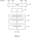
- Figure 12 displays an architecture of a learning/classification process of regions of interest that are tracked in a scene according to some embodiments of the invention.
- a deep learning classification technique based on convolutional neural networks is used.
- the assumption that a CNN classifier is well suited to the problem to be solved is based on the idea that patterns that are present in a vignette have a significant probability to be present elsewhere.
- a CNN is a multi-stage learning method where the neurons are locally connected and not connected to all the layers of the network. Groups of neurons sharing the same parameters are spread out regularly to cover the entire image. This allows a more computationally efficient processing.
- a description of a CNN classifier of the prior art may be found in Garschik and alii, "Rich Feature Hierarchies for Accurate Object Detection and Semantic Detection", 2014 I3E Conference on Computer Vision and Pattern Recognition, CVPR 2014, Colombus, OH, USA, pp. 580-587, 2014 .
- Classification and learning are performed by a CNN at the same time.
- a number of different architectures of CNN may be used to implement the invention.
- the architecture presented on figure is therefore illustrative only and not limitative.
- a method described in Viola and alii “Rapid Object Detection Using a Boosted Cascade of Simple Features", 2001 I3E, Computer Society Conference on Computer Vision and Pattern Recognition (CVPR 2001), Kawai, HI, USA, pp. 511-518, 2001 , or in Dalal et alii "Histograms of Oriented Gradients for Human Detection", International Conference on Computer Vision and Patter Recognition, vol. 2, pp. 886-893, June 2005 , or in Lowe, "Object Recognition from Local Scale-Invariant Features", Proceedings of the International Conference on Computer Vision, vol. 2, ICCV '99, pp. 1150-, 1999 .
- the CNN used to classify the objects of interest detected, tracked and conditioned into Vignettes V k comprises:
- a number of parameters of the various modules of the CNN may be tuned by trial and error to adjust performance in terms of the best compromise between true and false positive and processing power needed, for instance the size of the input vignettes, the dimensions of the kernels of the CLs, the use of a cascading approach to eliminate the false positives, the initialization of the FCL to increase the speed of convergence. For instance a matrix of 112x112 pixels for the vignette at the output of the tracking process has been determined to be a good choice.
Landscapes
- Engineering & Computer Science (AREA)
- General Physics & Mathematics (AREA)
- Physics & Mathematics (AREA)
- Theoretical Computer Science (AREA)
- Multimedia (AREA)
- Computer Vision & Pattern Recognition (AREA)
- Data Mining & Analysis (AREA)
- General Engineering & Computer Science (AREA)
- Signal Processing (AREA)
- Bioinformatics & Cheminformatics (AREA)
- Bioinformatics & Computational Biology (AREA)
- Evolutionary Biology (AREA)
- Evolutionary Computation (AREA)
- Artificial Intelligence (AREA)
- Life Sciences & Earth Sciences (AREA)
- Closed-Circuit Television Systems (AREA)
- Studio Devices (AREA)
- Image Analysis (AREA)
Claims (13)
- Vorrichtung (100), die Folgendes umfasst:- eine oder mehrere Quellen (40, 41) von Infrarotlicht,- eine oder mehrere Quellen (50, 51) von sichtbarem Licht,- einen Bildsensor (10),- eine Verarbeitungseinheit (20), die dafür konfiguriert ist, eine Reihe von Bildern eines Bereichs von Interesse zu analysieren, die durch den Bildsensor ausgegeben werden,- eine Steuereinheit (30), die dafür konfiguriert ist, eines oder mehrere von einer Aktivierung der einen oder der mehreren Quellen von sichtbarem Licht oder einem Alarmauf Grundlage eines von der Verarbeitungseinheit empfangenen Befehls zu erzeugen,wobei die Analyse Folgendes umfasst:Erkennen eines sich bewegenden Vordergrundes in der Reihe von Bildern des Bereichs von Interesse, Verfolgen eines oder mehrerer kennzeichnender Merkmale in dem sich bewegenden Vordergrund und Klassifizieren des einen oder der mehreren kennzeichnenden Merkmale in zwei oder mehr Arten von Objekten von Interesse,wobei eine Art eines Objekts von Interesse einen Befehl bestimmt, der durch die Verarbeitungseinheit an die Steuereinheit gesendet wird,wobei die Vorrichtung dadurch gekennzeichnet ist, dassdas Klassifizieren das Verwenden eines neuronalen Netzes umfasst, wobei das neuronale Netz ein Faltungsneuronalnetz-Klassifizierer ist.
- Vorrichtung nach Anspruch 1, das ferner durch eine Kommunikationsverbindung mit einem Netz verbunden werden kann, wobei in dem Fall, in dem die Steuereinheit dafür konfiguriert ist, einen Alarm zu erzeugen, die Steuereinheit ferner dafür konfiguriert ist, den Alarm auf der Kommunikationsverbindung an ein Anwendergerät zu senden.
- Vorrichtung nach Anspruch 2, wobei in dem Fall, in dem die Steuereinheit dafür konfiguriert ist, einen Alarm zu erzeugen, die Steuereinheit ferner dafür konfiguriert ist, auszulösen, dass Bilder des Objekts von Interesse auf der Kommunikationsverbindung an das Anwendergerät gesendet werden.
- Vorrichtung nach einem der Ansprüche 1 bis 3, wobei das Erkennen einen Y-Leuchtdichtewert in einer YUV-Codierung von Bildpunkten in der Reihe von Bildern verwendet.
- Vorrichtung nach einem der Ansprüche 1 bis 4, wobei das Verfolgen das Zuweisen eines Wertes eines guten Merkmals zu einem kennzeichnenden Merkmal in umgrenzten Blöcken, die durch das Erkennen ausgegeben werden, umfasst, falls ein Zähler von korrelierten Bewegungen des kennzeichnenden Merkmals gesteigert wird und ein Zähler von Unbeweglichkeit gleich null ist.
- Vorrichtung nach Anspruch 5, wobei das Verfolgen ferner das Erzeugen einer Vignette mit einem umgrenzten Block umfasst, der eine Anzahl von guten Merkmalen aufweist, die höher ist als ein Schwellenwert.
- Vorrichtung nach einem der Ansprüche 1 bis 6, wobei das neuronale Netz eine oder mehrere vollständig verbundene Schichten umfasst.
- Vorrichtung nach einem der Ansprüche 1 bis 7, wobei:- die Kamera (10) ein Objektiv (Ob) und einen Sensor (Ca) für Infrarotlicht und sichtbares Licht umfasst,- die mindestens eine Quelle (40) von Infrarotlicht einen Abstrahlungskegel (c40) von Infrarotlicht aufweist,- die mindestens eine Quelle (50) von sichtbarem Licht einen Abstrahlungskegel (c50) von sichtbarem Licht aufweist,- es keine Überschneidung zwischen dem Objektiv (Ob) der Kamera (10) einerseits und den Abstrahlungskegeln (c40, c50) von Infrarotlicht und von sichtbarem Licht andererseits gibt.
- Vorrichtung nach Anspruch 8, wobei das Objektiv (Ob) eine Umdrehungsachse A aufweist und eine erste Fläche (f1) aufweist, die einen Normalvektor (nf1), der zu dem Sensor (Ca) hin ausgerichtet ist, und eine zweite Fläche (f2) aufweist, die einen Normalvektor (nf2), der zur der Umgebung hin ausgerichtet ist, umfasst, und wobei eine erste Ebene (P1), tangential zu der ersten Fläche (f1) und in rechtem Winkel zu der Umdrehungsachse A, einen ersten Halbraum (dE1), zu dem der Sensor (Ca) gehört, und einen zweiten Halbraum (dE2), zu dem die zweite Fläche (f2) des Objektivs (Ob) und die Umgebung gehören, definiert und:- der Abstrahlungskegel (c40) der mindestens einen Quelle (40) von Infrarotlicht einen Scheitel (s40) aufweist, der in dem zweiten Halbraum (dE2) angeordnet ist,- der Abstrahlungskegel (c50) der mindestens einen Quelle (50) von sichtbarem Licht einen Scheitel (s50) aufweist, der in dem zweiten Halbraum (dE2) angeordnet ist.
- Vorrichtung nach Anspruch 9, wobei:- die mindestens eine Quelle (40) von Infrarotlicht einen Abstrahlungskegel (c40) mit einer Achse A40 aufweist,- die mindestens eine Quelle (50) von sichtbarem Licht einen Abstrahlungskegel (c50) mit einer Achse A50 aufweist und- die Kamera (10) einen Absorptionskegel mit einer Achse A aufweist,- in dem zweiten Halbraum (dE2) die Entfernung zwischen der Achse A40 und der Achse A beim Bewegen, weg von der ersten Ebene (P1), konstant oder zunehmend ist und- in dem zweiten Halbraum (dE2) die Entfernung zwischen der Achse A50 und der Achse A beim Bewegen, weg von der ersten Ebene (P1), konstant oder zunehmend ist.
- Vorrichtung nach einem der Ansprüche 8 bis 10, die eine Vielzahl von Quellen (50, 51) von sichtbarem Licht umfasst, wobei jede Quelle von sichtbarem Licht einen Abstrahlungskegel (c50, c51) aufweist, der eine Achse (A50, A51) aufweist, wobei in dem ersten Halbraum (dE1), für jede Quelle (50, 51) von sichtbarem Licht der Vielzahl von Quellen von sichtbarem Licht, die Entfernung zwischen der Achse des Abstrahlungskegels der Quelle und der Achse des Abstrahlungskegels jeder anderen Quelle beim Bewegen, weg von der ersten Ebene (P1), konstant oder zunehmend ist.
- Vorrichtung nach einem der Ansprüche 8 bis 11, wobei das Objektiv (Ob) eine Umdrehungsachse A aufweist, wobei sie ferner ein Schutzelement (60, 61, 62) für die mindestens eine Quelle (40) von Infrarotlicht, für die mindestens eine Quelle (50) von sichtbarem Licht und für das Objektiv (Ob) der Kamera (10) umfasst, wobei das Schutzelement für das Infrarotlicht und für das sichtbare Licht durchlässig ist, wobei sich das Schutzelement im Wesentlichen entlang einer Ebene, im rechten Winkel zu der Umdrehungsachse A, erstreckt.
- Verfahren zum Überwachen eines Bereichs von Interesse, das Folgendes umfasst:- Beleuchten des Bereichs von Interesse mit einer oder mehreren Quellen (40, 41) von Infrarotlicht,- Erfassen von Reihen von Bildern des Bereichs von Interesse durch einen Bildsensor (10),- Analysieren der Reihe von Bildern des Bereichs von Interesse, die durch den Bildsensor ausgegeben werden, durch eine Verarbeitungseinheit (20),- Erzeugen von einem oder mehreren von einer Aktivierung von einer oder mehreren Quellen (50, 51) von sichtbarem Licht oder einem Alarm auf Grundlage eines von der Verarbeitungseinheit empfangenen Befehls durch eine Steuereinheit (30),wobei die Analyse Folgendes umfasst:Erkennen eines sich bewegenden Vordergrundes in der Reihe von Bildern des Bereichs von Interesse, Verfolgen eines oder mehrerer kennzeichnender Merkmale in dem sich bewegenden Vordergrund und Klassifizieren des einen oder der mehreren kennzeichnenden Merkmale in zwei oder mehr Arten von Objekten von Interesse,wobei eine Art eines Objekts von Interesse einen Befehl bestimmt, der durch die Verarbeitungseinheit an die Steuereinheit gesendet wird,wobei das Verfahren dadurch gekennzeichnet ist, dass das Klassifizieren das Verwenden eines neuronalen Netzes umfasst, wobei das neuronale Netz ein Faltungsneuronalnetz-Klassifizierer ist.
Applications Claiming Priority (2)
| Application Number | Priority Date | Filing Date | Title |
|---|---|---|---|
| FR1650016A FR3046519B1 (fr) | 2016-01-04 | 2016-01-04 | Dispositif d'eclairage automatique |
| PCT/EP2017/050111 WO2017118647A1 (en) | 2016-01-04 | 2017-01-04 | Automatic lighting and security device |
Publications (3)
| Publication Number | Publication Date |
|---|---|
| EP3400405A1 EP3400405A1 (de) | 2018-11-14 |
| EP3400405C0 EP3400405C0 (de) | 2024-07-24 |
| EP3400405B1 true EP3400405B1 (de) | 2024-07-24 |
Family
ID=56069025
Family Applications (1)
| Application Number | Title | Priority Date | Filing Date |
|---|---|---|---|
| EP17700048.6A Active EP3400405B1 (de) | 2016-01-04 | 2017-01-04 | Automatisches beleuchtungs- und sicherheitssystem |
Country Status (7)
| Country | Link |
|---|---|
| US (1) | US11227165B2 (de) |
| EP (1) | EP3400405B1 (de) |
| KR (1) | KR102148586B1 (de) |
| CN (1) | CN109154435B (de) |
| ES (1) | ES2992859T3 (de) |
| FR (1) | FR3046519B1 (de) |
| WO (1) | WO2017118647A1 (de) |
Families Citing this family (5)
| Publication number | Priority date | Publication date | Assignee | Title |
|---|---|---|---|---|
| EP3572972A1 (de) * | 2018-05-23 | 2019-11-27 | IDEMIA Identity & Security Germany AG | Erweitertes neuronales faltungsnetzwerk für die dokumentenanalyse |
| JP7126864B2 (ja) * | 2018-05-25 | 2022-08-29 | キヤノンメディカルシステムズ株式会社 | 医用信号処理装置及び学習プログラム |
| EP3798620A1 (de) * | 2019-09-25 | 2021-03-31 | ETA SA Manufacture Horlogère Suisse | System und verfahren zur steuerung einer beleuchtung eines bestimmten bereichs, das mindestens ein durch einen benutzer beeinflussbares objekt umfasst |
| EP3876211A1 (de) | 2020-03-06 | 2021-09-08 | Signify Holding B.V. | Auswählen einer lichtquelle zur aktivierung basierend auf einer art und/oder wahrscheinlichkeit von menschlicher anwesenheit |
| US20250254274A1 (en) * | 2024-02-05 | 2025-08-07 | Cambridge Mobile Telematics Inc. | Low-power techniques for automatically detecting anomalous activity in an unoccupied vehicle |
Family Cites Families (21)
| Publication number | Priority date | Publication date | Assignee | Title |
|---|---|---|---|---|
| US6192155B1 (en) * | 1998-09-16 | 2001-02-20 | Xerox Corporation | Systems and methods for reducing boundary artifacts in hybrid compression |
| JP2003008954A (ja) | 2001-06-20 | 2003-01-10 | Fujitsu General Ltd | ドーム型監視カメラ装置 |
| US7627171B2 (en) * | 2003-07-03 | 2009-12-01 | Videoiq, Inc. | Methods and systems for detecting objects of interest in spatio-temporal signals |
| US20050163345A1 (en) * | 2003-12-03 | 2005-07-28 | Safehouse International Limited | Analysing image data |
| GB2409123B (en) * | 2003-12-03 | 2009-07-01 | Safehouse Internat Inc | Analysing image data |
| US20070122000A1 (en) * | 2005-11-29 | 2007-05-31 | Objectvideo, Inc. | Detection of stationary objects in video |
| US8150155B2 (en) * | 2006-02-07 | 2012-04-03 | Qualcomm Incorporated | Multi-mode region-of-interest video object segmentation |
| US9215781B2 (en) * | 2008-04-16 | 2015-12-15 | Avo Usa Holding 2 Corporation | Energy savings and improved security through intelligent lighting systems |
| WO2013052383A1 (en) * | 2011-10-07 | 2013-04-11 | Flir Systems, Inc. | Smart surveillance camera systems and methods |
| JP5480600B2 (ja) * | 2009-11-13 | 2014-04-23 | パナソニック株式会社 | 照明制御システム |
| CN101930653B (zh) | 2009-12-22 | 2011-11-30 | 广州广电运通金融电子股份有限公司 | 异物检测装置及其检测方法以及具有该装置的自动柜员机 |
| CN102118554B (zh) | 2010-01-04 | 2014-07-02 | 鸿富锦精密工业(深圳)有限公司 | 监控系统 |
| CN102510480B (zh) | 2011-11-04 | 2014-02-05 | 大连海事大学 | 驾驶员视线自动校准和跟踪系统 |
| WO2013109609A2 (en) | 2012-01-17 | 2013-07-25 | Leap Motion, Inc. | Enhanced contrast for object detection and characterization by optical imaging |
| US20130329987A1 (en) * | 2012-06-11 | 2013-12-12 | Genesis Group Inc. | Video segmentation method |
| US9285893B2 (en) | 2012-11-08 | 2016-03-15 | Leap Motion, Inc. | Object detection and tracking with variable-field illumination devices |
| US9436692B1 (en) * | 2013-06-25 | 2016-09-06 | Emc Corporation | Large scale video analytics architecture |
| US9165444B2 (en) * | 2013-07-26 | 2015-10-20 | SkyBell Technologies, Inc. | Light socket cameras |
| US9454819B1 (en) * | 2015-06-03 | 2016-09-27 | The United States Of America As Represented By The Secretary Of The Air Force | System and method for static and moving object detection |
| US20180048894A1 (en) * | 2016-08-11 | 2018-02-15 | Qualcomm Incorporated | Methods and systems of performing lighting condition change compensation in video analytics |
| US10628961B2 (en) * | 2017-10-13 | 2020-04-21 | Qualcomm Incorporated | Object tracking for neural network systems |
-
2016
- 2016-01-04 FR FR1650016A patent/FR3046519B1/fr active Active
-
2017
- 2017-01-04 WO PCT/EP2017/050111 patent/WO2017118647A1/en not_active Ceased
- 2017-01-04 EP EP17700048.6A patent/EP3400405B1/de active Active
- 2017-01-04 US US16/067,920 patent/US11227165B2/en active Active
- 2017-01-04 CN CN201780014842.4A patent/CN109154435B/zh active Active
- 2017-01-04 ES ES17700048T patent/ES2992859T3/es active Active
- 2017-01-04 KR KR1020187022541A patent/KR102148586B1/ko active Active
Also Published As
| Publication number | Publication date |
|---|---|
| EP3400405C0 (de) | 2024-07-24 |
| EP3400405A1 (de) | 2018-11-14 |
| CN109154435A (zh) | 2019-01-04 |
| US11227165B2 (en) | 2022-01-18 |
| WO2017118647A1 (en) | 2017-07-13 |
| US20200274997A1 (en) | 2020-08-27 |
| KR102148586B1 (ko) | 2020-08-27 |
| FR3046519A1 (fr) | 2017-07-07 |
| FR3046519B1 (fr) | 2022-11-04 |
| CN109154435B (zh) | 2020-07-07 |
| ES2992859T3 (en) | 2024-12-18 |
| KR20180100406A (ko) | 2018-09-10 |
Similar Documents
| Publication | Publication Date | Title |
|---|---|---|
| Tyagi et al. | A review paper on real-time video analysis in dense environment for surveillance system | |
| EP2798578B1 (de) | Clusterbasierte objektklassifizierung | |
| US9299162B2 (en) | Multi-mode video event indexing | |
| Ibrahim | A comprehensive review on intelligent surveillance systems | |
| EP3400405B1 (de) | Automatisches beleuchtungs- und sicherheitssystem | |
| Ko et al. | Background subtraction on distributions | |
| Sen-Ching et al. | Robust techniques for background subtraction in urban traffic video | |
| US9870617B2 (en) | Apparatus and methods for saliency detection based on color occurrence analysis | |
| US20070273765A1 (en) | Method for Detecting Desired Objects in a Highly Dynamic Environment by a Monitoring System | |
| WO2014083070A2 (en) | Systems and methods to classify moving airplanes in airports | |
| Jeyabharathi et al. | Vehicle Tracking and Speed Measurement system (VTSM) based on novel feature descriptor: Diagonal Hexadecimal Pattern (DHP) | |
| CN114821441B (zh) | 联合ads-b信息的基于深度学习的机场场面运动目标识别方法 | |
| Surendar et al. | Animal tracking using background subtraction on multi threshold segmentation | |
| Buch et al. | Local feature saliency classifier for real-time intrusion monitoring | |
| Kolluri et al. | MM_Fast_RCNN_ResNet: Construction of multimodal faster rcnn inception and resnet v2 for pedestrian tracking and detection | |
| Bobulski et al. | Background segmentation method for autonomous car | |
| Guler et al. | Video scene assessment with unattended sensors | |
| Ouyang et al. | Robust component-based car detection in aerial imagery with new segmentation techniques | |
| Martínez-Martín et al. | Motion Detection in General Backgrounds | |
| ILYAKHUNOV et al. | INTERNATIONAL JOURNAL OF PROFESSIONAL SCIENCE |
Legal Events
| Date | Code | Title | Description |
|---|---|---|---|
| STAA | Information on the status of an ep patent application or granted ep patent |
Free format text: STATUS: UNKNOWN |
|
| STAA | Information on the status of an ep patent application or granted ep patent |
Free format text: STATUS: THE INTERNATIONAL PUBLICATION HAS BEEN MADE |
|
| PUAI | Public reference made under article 153(3) epc to a published international application that has entered the european phase |
Free format text: ORIGINAL CODE: 0009012 |
|
| STAA | Information on the status of an ep patent application or granted ep patent |
Free format text: STATUS: REQUEST FOR EXAMINATION WAS MADE |
|
| 17P | Request for examination filed |
Effective date: 20180801 |
|
| AK | Designated contracting states |
Kind code of ref document: A1 Designated state(s): AL AT BE BG CH CY CZ DE DK EE ES FI FR GB GR HR HU IE IS IT LI LT LU LV MC MK MT NL NO PL PT RO RS SE SI SK SM TR |
|
| AX | Request for extension of the european patent |
Extension state: BA ME |
|
| RIN1 | Information on inventor provided before grant (corrected) |
Inventor name: MOUTET, KELVIN Inventor name: ELVIRA, DAVID Inventor name: FEHLI, MEHDI Inventor name: POTTER, FREDERIC Inventor name: LUC, PAULINE |
|
| DAV | Request for validation of the european patent (deleted) | ||
| DAX | Request for extension of the european patent (deleted) | ||
| STAA | Information on the status of an ep patent application or granted ep patent |
Free format text: STATUS: EXAMINATION IS IN PROGRESS |
|
| 17Q | First examination report despatched |
Effective date: 20210507 |
|
| GRAP | Despatch of communication of intention to grant a patent |
Free format text: ORIGINAL CODE: EPIDOSNIGR1 |
|
| STAA | Information on the status of an ep patent application or granted ep patent |
Free format text: STATUS: GRANT OF PATENT IS INTENDED |
|
| RIC1 | Information provided on ipc code assigned before grant |
Ipc: G06V 20/56 20220101ALI20240126BHEP Ipc: G06V 10/25 20220101ALI20240126BHEP Ipc: G06V 10/143 20220101ALI20240126BHEP Ipc: G08B 13/196 20060101ALI20240126BHEP Ipc: H05B 47/125 20200101ALI20240126BHEP Ipc: F21V 23/04 20060101AFI20240126BHEP |
|
| INTG | Intention to grant announced |
Effective date: 20240221 |
|
| GRAS | Grant fee paid |
Free format text: ORIGINAL CODE: EPIDOSNIGR3 |
|
| GRAA | (expected) grant |
Free format text: ORIGINAL CODE: 0009210 |
|
| STAA | Information on the status of an ep patent application or granted ep patent |
Free format text: STATUS: THE PATENT HAS BEEN GRANTED |
|
| AK | Designated contracting states |
Kind code of ref document: B1 Designated state(s): AL AT BE BG CH CY CZ DE DK EE ES FI FR GB GR HR HU IE IS IT LI LT LU LV MC MK MT NL NO PL PT RO RS SE SI SK SM TR |
|
| REG | Reference to a national code |
Ref country code: GB Ref legal event code: FG4D |
|
| REG | Reference to a national code |
Ref country code: CH Ref legal event code: EP |
|
| REG | Reference to a national code |
Ref country code: IE Ref legal event code: FG4D Ref country code: DE Ref legal event code: R096 Ref document number: 602017083486 Country of ref document: DE |
|
| U01 | Request for unitary effect filed |
Effective date: 20240809 |
|
| U07 | Unitary effect registered |
Designated state(s): AT BE BG DE DK EE FI FR IT LT LU LV MT NL PT RO SE SI Effective date: 20240923 |
|
| REG | Reference to a national code |
Ref country code: ES Ref legal event code: FG2A Ref document number: 2992859 Country of ref document: ES Kind code of ref document: T3 Effective date: 20241218 |
|
| PG25 | Lapsed in a contracting state [announced via postgrant information from national office to epo] |
Ref country code: NO Free format text: LAPSE BECAUSE OF FAILURE TO SUBMIT A TRANSLATION OF THE DESCRIPTION OR TO PAY THE FEE WITHIN THE PRESCRIBED TIME-LIMIT Effective date: 20241024 |
|
| PG25 | Lapsed in a contracting state [announced via postgrant information from national office to epo] |
Ref country code: GR Free format text: LAPSE BECAUSE OF FAILURE TO SUBMIT A TRANSLATION OF THE DESCRIPTION OR TO PAY THE FEE WITHIN THE PRESCRIBED TIME-LIMIT Effective date: 20241025 Ref country code: PL Free format text: LAPSE BECAUSE OF FAILURE TO SUBMIT A TRANSLATION OF THE DESCRIPTION OR TO PAY THE FEE WITHIN THE PRESCRIBED TIME-LIMIT Effective date: 20240724 |
|
| PG25 | Lapsed in a contracting state [announced via postgrant information from national office to epo] |
Ref country code: IS Free format text: LAPSE BECAUSE OF FAILURE TO SUBMIT A TRANSLATION OF THE DESCRIPTION OR TO PAY THE FEE WITHIN THE PRESCRIBED TIME-LIMIT Effective date: 20241124 |
|
| PG25 | Lapsed in a contracting state [announced via postgrant information from national office to epo] |
Ref country code: HR Free format text: LAPSE BECAUSE OF FAILURE TO SUBMIT A TRANSLATION OF THE DESCRIPTION OR TO PAY THE FEE WITHIN THE PRESCRIBED TIME-LIMIT Effective date: 20240724 |
|
| PG25 | Lapsed in a contracting state [announced via postgrant information from national office to epo] |
Ref country code: RS Free format text: LAPSE BECAUSE OF FAILURE TO SUBMIT A TRANSLATION OF THE DESCRIPTION OR TO PAY THE FEE WITHIN THE PRESCRIBED TIME-LIMIT Effective date: 20241024 |
|
| PG25 | Lapsed in a contracting state [announced via postgrant information from national office to epo] |
Ref country code: RS Free format text: LAPSE BECAUSE OF FAILURE TO SUBMIT A TRANSLATION OF THE DESCRIPTION OR TO PAY THE FEE WITHIN THE PRESCRIBED TIME-LIMIT Effective date: 20241024 Ref country code: PL Free format text: LAPSE BECAUSE OF FAILURE TO SUBMIT A TRANSLATION OF THE DESCRIPTION OR TO PAY THE FEE WITHIN THE PRESCRIBED TIME-LIMIT Effective date: 20240724 Ref country code: NO Free format text: LAPSE BECAUSE OF FAILURE TO SUBMIT A TRANSLATION OF THE DESCRIPTION OR TO PAY THE FEE WITHIN THE PRESCRIBED TIME-LIMIT Effective date: 20241024 Ref country code: IS Free format text: LAPSE BECAUSE OF FAILURE TO SUBMIT A TRANSLATION OF THE DESCRIPTION OR TO PAY THE FEE WITHIN THE PRESCRIBED TIME-LIMIT Effective date: 20241124 Ref country code: HR Free format text: LAPSE BECAUSE OF FAILURE TO SUBMIT A TRANSLATION OF THE DESCRIPTION OR TO PAY THE FEE WITHIN THE PRESCRIBED TIME-LIMIT Effective date: 20240724 Ref country code: GR Free format text: LAPSE BECAUSE OF FAILURE TO SUBMIT A TRANSLATION OF THE DESCRIPTION OR TO PAY THE FEE WITHIN THE PRESCRIBED TIME-LIMIT Effective date: 20241025 |
|
| PG25 | Lapsed in a contracting state [announced via postgrant information from national office to epo] |
Ref country code: SM Free format text: LAPSE BECAUSE OF FAILURE TO SUBMIT A TRANSLATION OF THE DESCRIPTION OR TO PAY THE FEE WITHIN THE PRESCRIBED TIME-LIMIT Effective date: 20240724 |
|
| U21 | Renewal fee for the european patent with unitary effect paid with additional fee |
Year of fee payment: 9 Effective date: 20250319 |
|
| PGFP | Annual fee paid to national office [announced via postgrant information from national office to epo] |
Ref country code: CH Payment date: 20250201 Year of fee payment: 9 |
|
| PG25 | Lapsed in a contracting state [announced via postgrant information from national office to epo] |
Ref country code: CZ Free format text: LAPSE BECAUSE OF FAILURE TO SUBMIT A TRANSLATION OF THE DESCRIPTION OR TO PAY THE FEE WITHIN THE PRESCRIBED TIME-LIMIT Effective date: 20240724 |
|
| PG25 | Lapsed in a contracting state [announced via postgrant information from national office to epo] |
Ref country code: SK Free format text: LAPSE BECAUSE OF FAILURE TO SUBMIT A TRANSLATION OF THE DESCRIPTION OR TO PAY THE FEE WITHIN THE PRESCRIBED TIME-LIMIT Effective date: 20240724 |
|
| PLBE | No opposition filed within time limit |
Free format text: ORIGINAL CODE: 0009261 |
|
| STAA | Information on the status of an ep patent application or granted ep patent |
Free format text: STATUS: NO OPPOSITION FILED WITHIN TIME LIMIT |
|
| 26N | No opposition filed |
Effective date: 20250425 |
|
| PG25 | Lapsed in a contracting state [announced via postgrant information from national office to epo] |
Ref country code: MC Free format text: LAPSE BECAUSE OF FAILURE TO SUBMIT A TRANSLATION OF THE DESCRIPTION OR TO PAY THE FEE WITHIN THE PRESCRIBED TIME-LIMIT Effective date: 20240724 |
|
| PGFP | Annual fee paid to national office [announced via postgrant information from national office to epo] |
Ref country code: GB Payment date: 20251220 Year of fee payment: 10 |
|
| PG25 | Lapsed in a contracting state [announced via postgrant information from national office to epo] |
Ref country code: IE Free format text: LAPSE BECAUSE OF NON-PAYMENT OF DUE FEES Effective date: 20250104 |
|
| U20 | Renewal fee for the european patent with unitary effect paid |
Year of fee payment: 10 Effective date: 20251217 |
|
| REG | Reference to a national code |
Ref country code: CH Ref legal event code: U11 Free format text: ST27 STATUS EVENT CODE: U-0-0-U10-U11 (AS PROVIDED BY THE NATIONAL OFFICE) Effective date: 20260201 |
|
| PGFP | Annual fee paid to national office [announced via postgrant information from national office to epo] |
Ref country code: ES Payment date: 20260202 Year of fee payment: 10 |