EP3400360B1 - Big bore running tool quick lock adaptor - Google Patents
Big bore running tool quick lock adaptor Download PDFInfo
- Publication number
- EP3400360B1 EP3400360B1 EP16895676.1A EP16895676A EP3400360B1 EP 3400360 B1 EP3400360 B1 EP 3400360B1 EP 16895676 A EP16895676 A EP 16895676A EP 3400360 B1 EP3400360 B1 EP 3400360B1
- Authority
- EP
- European Patent Office
- Prior art keywords
- collet
- liner hanger
- assembly
- single piece
- hanger body
- Prior art date
- Legal status (The legal status is an assumption and is not a legal conclusion. Google has not performed a legal analysis and makes no representation as to the accuracy of the status listed.)
- Active
Links
- 238000000034 method Methods 0.000 claims description 20
- 238000012546 transfer Methods 0.000 claims description 11
- 230000013011 mating Effects 0.000 claims description 7
- 230000008878 coupling Effects 0.000 claims description 6
- 238000010168 coupling process Methods 0.000 claims description 6
- 238000005859 coupling reaction Methods 0.000 claims description 6
- 238000012360 testing method Methods 0.000 description 11
- 241000282472 Canis lupus familiaris Species 0.000 description 9
- 238000010586 diagram Methods 0.000 description 6
- ZZUFCTLCJUWOSV-UHFFFAOYSA-N furosemide Chemical compound C1=C(Cl)C(S(=O)(=O)N)=CC(C(O)=O)=C1NCC1=CC=CO1 ZZUFCTLCJUWOSV-UHFFFAOYSA-N 0.000 description 5
- 238000009434 installation Methods 0.000 description 5
- 238000004519 manufacturing process Methods 0.000 description 4
- 238000007789 sealing Methods 0.000 description 4
- 238000013461 design Methods 0.000 description 3
- 230000015572 biosynthetic process Effects 0.000 description 2
- 238000004891 communication Methods 0.000 description 2
- 238000005553 drilling Methods 0.000 description 2
- 238000012986 modification Methods 0.000 description 2
- 230000004048 modification Effects 0.000 description 2
- 229910000831 Steel Inorganic materials 0.000 description 1
- 238000000576 coating method Methods 0.000 description 1
- 230000006835 compression Effects 0.000 description 1
- 238000007906 compression Methods 0.000 description 1
- 230000000994 depressogenic effect Effects 0.000 description 1
- 238000007667 floating Methods 0.000 description 1
- 239000012530 fluid Substances 0.000 description 1
- 239000000463 material Substances 0.000 description 1
- 239000011435 rock Substances 0.000 description 1
- 239000010959 steel Substances 0.000 description 1
- 230000004936 stimulating effect Effects 0.000 description 1
- 239000000758 substrate Substances 0.000 description 1
- 238000011179 visual inspection Methods 0.000 description 1
Images


Classifications
-
- E—FIXED CONSTRUCTIONS
- E21—EARTH DRILLING; MINING
- E21B—EARTH DRILLING, e.g. DEEP DRILLING; OBTAINING OIL, GAS, WATER, SOLUBLE OR MELTABLE MATERIALS OR A SLURRY OF MINERALS FROM WELLS
- E21B23/00—Apparatus for displacing, setting, locking, releasing, or removing tools, packers or the like in the boreholes or wells
- E21B23/02—Apparatus for displacing, setting, locking, releasing, or removing tools, packers or the like in the boreholes or wells for locking the tools or the like in landing nipples or in recesses between adjacent sections of tubing
-
- E—FIXED CONSTRUCTIONS
- E21—EARTH DRILLING; MINING
- E21B—EARTH DRILLING, e.g. DEEP DRILLING; OBTAINING OIL, GAS, WATER, SOLUBLE OR MELTABLE MATERIALS OR A SLURRY OF MINERALS FROM WELLS
- E21B23/00—Apparatus for displacing, setting, locking, releasing, or removing tools, packers or the like in the boreholes or wells
-
- E—FIXED CONSTRUCTIONS
- E21—EARTH DRILLING; MINING
- E21B—EARTH DRILLING, e.g. DEEP DRILLING; OBTAINING OIL, GAS, WATER, SOLUBLE OR MELTABLE MATERIALS OR A SLURRY OF MINERALS FROM WELLS
- E21B43/00—Methods or apparatus for obtaining oil, gas, water, soluble or meltable materials or a slurry of minerals from wells
- E21B43/02—Subsoil filtering
- E21B43/10—Setting of casings, screens, liners or the like in wells
Definitions
- the running tool now has a built in test port for O-ring seal hydro testing, which saves design time and cost.
- two O-rings instead of one, now form a seal between the collet prop mandrel and the inner diameter of the liner hanger.
- a pressure port located between the two O-rings communicates to a sealed annular chamber bounded by the inner collet mandrel and the outer collet mandrel sub assembly and O-rings that are placed between the components.
Description
- The present disclosure relates generally to equipment utilized and operations performed in conjunction with oil and gas exploration and production, and more particularly to a method and coupler assembly for conveying a single piece liner hanger body.
- Once a well has been drilled, if it is to become a production well, the well must undergo completion. This principally involves preparing the bottom of the hole to the required specifications, running in the production tubing and its associated down hole tools, as well as perforating and stimulating the well. Typically, the lower completion of the well is set across the productive zone using a liner hanger system, which anchors the lower completion to the production casing string.
- The installation of the liner hanger system and these strings presents a variety of challenges. One such challenge is that third party supplied thread connections do not always provide the performance needed to meet the sealing, tensile and compression requirements for the hanger assembly. Third party threads have recently come under close scrutiny during gas testing of liner hangers and have performance issues when gas tight bubble free connections are required.
-
US20120222868A1 discloses an expansion cone assembly for setting a liner hanger in a wellbore casing.US20140352944A1 discloses a packoff for liner deployment assembly.WO2015/034489 discloses a running tool with retractable collet for liner string installation in a wellbore.US 2008257560 A1 discloses a running tool for conveying a single piece liner hanger body. - Accordingly, as will be described herein, one purpose of the disclosed embodiments is to incorporate new and improved geometry such as a one piece hanger body. Additionally, one advantage of the disclosed embodiments is that it offers a means to easily hydro test critical sealing features that previously required expensive test fixtures. Other aspects and advantages of the disclosed embodiments will be apparent from the following description.
- Illustrative embodiments of the present invention are described in detail below with reference to the attached drawing figures:
-
FIG. 1A is a diagram of an on-shore well in which a tool string is deployed according to an illustrative embodiment; -
FIG. 1B is a diagram of an off-shore well in which a tool string is deployed according to an illustrative embodiment; -
FIG. 2 is a diagram of the inner sub-assembly components of a coupler assembly for conveying a liner hanger to a running tool according to an illustrative embodiment; -
FIGS. 3-14 are diagrams illustrating a method of assembling the inner sub-assembly components of the coupler assembly according to an illustrative embodiment; -
FIGS. 15-24 are diagrams illustrating a method of assembling the outer sub-assembly components of the coupler assembly according to an illustrative embodiment; -
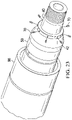
FIG. 25 is a diagram of an assembled coupler assembly according to an illustrative embodiment; and -
FIG. 26 illustrates a cross-sectional view of the components of the assembled coupler assembly according to an illustrative embodiment. - In the following detailed description of the illustrative embodiments, reference is made to the accompanying drawings that form a part hereof. To avoid detail not necessary to enable those skilled in the art to practice the embodiments described herein, the description may omit certain information known to those skilled in the art. The following detailed description is, therefore, not to be taken in a limiting sense, and the scope of the invention is defined only by the appended claims.
- Currently, as part of the well completion process, a big bore running tool is used to set a two piece liner hanger consisting of an upper expandable body and a setting sleeve that is threaded to the bottom of it. The illustrative embodiments modify the current big bore running tool to enable conveying of a big bore liner hanger with a single piece hanger body. As will be described, the disclosed embodiments maintains an assembly method known as "top down" build whereby the assembly begins with the topmost components and parts are added as you move towards the bottom of the running tool.
- Beginning with
FIG. 1A , a schematic view of arig 104 in which atool string 128 is deployed that includes acoupler assembly 100 is presented in accordance with an illustrative embodiment. Therig 104 is positioned onshore at asurface 124 of awell 102. Thewell 102 includes awellbore 130 that extends from thesurface 124 of thewell 102 to a subterranean substrate orformation 134.Tool string 128 may deploy running tools used to place or setdownhole equipment 144 such as, but not limited to, liner hangers, plugs and packers. For instance, in one embodiment, thecoupler assembly 100 may be used to convey or set a liner hanger to a running tool. - Similarly,
FIG. 1B illustrates a schematic view of anoffshore platform 142 operating atool string 128 that includes thecoupler assembly 100 according to an illustrative embodiment. Thecoupler assembly 100 inFIG. 1B may be deployed in asubsea well 138 accessed by theoffshore platform 142. Theoffshore platform 142 may be a floating platform or may instead be anchored to aseabed 140. -
FIGS. 1A-1B each illustrate possible uses or deployments of thecoupler assembly 100, which in either instance may be used intool string 128 to deploy thedownhole equipment 144. In the embodiments illustrated inFIG. 1A and1B , thewellbore 130 has been formed by a drilling process in which dirt, rock and other subterranean material has been cut from theformation 134 by a drill bit operated via a drill string to create thewellbore 130. During or after the drilling process, a portion of the wellbore may be cased with a casing (not illustrated inFIGS. 1A and1B ). In other embodiments, the wellbore may be maintained in an open-hole configuration without casing. - The
tool string 128 may include sections of tubing, each of which are joined to adjacent tubing by threaded or other connection types, such ascoupler assembly 100. Thetool string 128 may refer to the collection of pipes, mandrels or tubes as a single component, or alternatively to the individual pipes, mandrels, or tubes that comprise the string. The term tool string is not meant to be limiting in nature and may include a running tool or any other type of tool string used to deploy thedownhole equipment 144 in the wellbore. In some embodiments, thetool string 128 may include a passage disposed longitudinally in thetool string 128 that is capable of allowing fluid communication between thesurface 124 of thewell 102 and adownhole location 136. It is noted that thecoupler assembly 100 described herein may be used to couple tubing segments in any suitable tool string, including, for example, a running tool for deploying a liner hanger. - The lowering of the
tool string 128 may be accomplished by alift assembly 106 associated with aderrick 114 positioned on or adjacent to therig 104 oroffshore platform 142. Thelift assembly 106 may include ahook 110, acable 108, a traveling block (not shown), and a hoist (not shown) that cooperatively work together to lift or lower aswivel 116 that is coupled an upper end of thetool string 128. Thetool string 128 may be raised or lowered as needed to add additional sections of tubing to thetool string 128 to position the distal end of thetool string 128 at thedownhole location 136 in thewellbore 130. - Referring now to the detail description of the
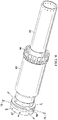
coupler assembly 100,FIG. 2 illustrates the inner sub-assembly components of thecoupler assembly 100 in accordance with one embodiment. In this illustrative embodiment, thecoupler assembly 100 is used for conveying aliner hanger 88 to a running tool 90 (illustrated inFIG. 18 ). The inner sub-assembly components of thecoupler assembly 100 include anut 47, aload transfer sleeve 46, alocking dog retainer 45, agarter spring 49, alocking dog 48, acollet 44, and anouter collet mandrel 43. As will be further described, once the inner sub-assembly of thecoupler assembly 100 is assembled, the assembled inner sub-assembly of thecoupler assembly 100 is inserted into theliner hanger 88. -
FIGS. 3-15 illustrate a method of assembling the inner sub-assembly components of thecoupler assembly 100 according to an illustrative embodiment. The assembly method starts withFIG. 3 where thecollet 44 is positioned over theouter collet mandrel 43. Thecollet 44 comprises a set ofcollet fingers 44f on one end and a threaded outer diameter on the other end. A set of apertures on thecollet 44 is aligned with holes on theouter collet mandrel 43. The holes on theouter collet mandrel 43 are threaded to enable a set of threadedscrews 78 to be received through the set of apertures on thecollet 44 and into the holes on theouter collet mandrel 43 for coupling thecollet 44 to theouter collet mandrel 43 as illustrated inFIG. 4 . - Next, the locking
dog 48 is positioned next to the upper end of thecollet 44 as shown inFIG. 5 . Thegarter spring 49 is installed onto the lockingdog 48 to keep it in place as illustrated inFIG. 6 . The lockingdog retainer 45 is then threaded to thecollet 44 over the lockingdog 48 and thegarter spring 49 as shown inFIG. 7 . Theload transfer sleeve 46 is then installed over the lockingdog retainer 45 and thecollet 44. Theload transfer sleeve 46 abuts a raised edge of the set ofcollet fingers 44f of thecollet 44 as shown inFIG. 8 . - The
nut 47 is then threaded onto the top end of theouter collet mandrel 43 as shown inFIG. 9 . In one embodiment, an O-ring 58 is placed in the outer diameter ofnut 47. The O-ring 58 is compressed during assembly between thenut 47 and the inside ofliner hanger 88 creating a seal at the interface as shown inFIG. 13-14 . A set ofscrews 70 is installed to secure thenut 47 to theouter collet mandrel 43 as shown inFIG. 10 to complete the assembly process of the inner sub-assembly components of thecoupler assembly 100. - The assembled inner sub-assembly of the
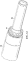
coupler assembly 100 is then inserted into the bottom end of theliner hanger 88 as indicated inFIG. 11 . As thecoupler assembly 100 is inserted into the bottom end of theliner hanger 88, the set ofcollet fingers 44f of thecollet 44 will collapse down to allow thecollet 44 to enter the bottom end of theliner hanger 88 as illustrated inFIGS. 12 and13 . -
FIG. 13 illustrates a cross section of the assembled inner sub-assembly of thecoupler assembly 100 as it is being inserted into the bottom end of theliner hanger 88. As shown, the set ofcollet fingers 44f of thecollet 44 is depressed as thecollet 44 is fully inserted into the bottom end of theliner hanger 88. In one embodiment, theouter collet mandrel 43 is long enough to allow the assembled inner sub-assembly of thecoupler assembly 100 to be manipulated by hand allowing the load bearingcollet fingers 44f to engage mating features near the bottom of theliner hanger 88 machined into the inner diameter of theliner hanger 88 as illustrated inFIG. 14 . In some embodiments, a circular pattern of radially drilled holes at the bottom end of theouter collet mandrel 43 can accept a steel bar that aids the application of torque when hand fitting the load bearing features of the collet 44 (i.e., thecollet fingers 44f) into the mating features in theliner hanger 88. In certain embodiments, the outside diameter features at the lower end of theouter collet mandrel 43 are much smaller than the inside diameter of theliner hanger 88 and allows for visual inspection to determine if thecollet fingers 44f have properly deployed into the mating features in theliner hanger 88. - Once the
collet fingers 44f have properly deployed into the mating features in theliner hanger 88, acollet prop mandrel 50 is inserted into the bottom end of theliner hanger 88 as indicated inFIG. 15 . At its top end, thecollet prop mandrel 50 includes a section of ridges for mating with thecollet fingers 44f in the inner sub-assembly of thecoupler assembly 100. In the depicted embodiment, thecollet prop mandrel 50 also includes an O-ring 80 located in the inner diameter at the top end, two O-rings 58 around its outer diameter following the ridged section, and an O-ring 81 located in the inner diameter at the bottom end of thecollet prop mandrel 50. - The
collet prop mandrel 50 is axially disposed until thecollet 44 is propped and thecollet prop mandrel 50 shoulders against theouter collet mandrel 43 with a portion of thecollet prop mandrel 50 extending out from the bottom of theliner hanger 88 as illustrated in the cross section shown inFIG. 16 . O-ring 80 is compressed during assembly between thecollet prop mandrel 50 and the outside ofouter collet mandrel 43 creating a seal at the interface as shown inFIG. 16 . Two O-rings 58 are compressed during assembly between thecollet prop mandrel 50 and the inside ofliner hanger 88 creating a seal at the interface as shown inFIG. 16 . - Two threaded
hollow plugs 79 is then inserted into test ports in thecollet prop mandrel 50 that are aligned with apertures in theouter collet mandrel 43 for securing thecollet prop mandrel 50 to the inner sub-assembly of thecoupler assembly 100 to complete the linerhanger coupler assembly 100 as illustrated inFIG. 17 . - The new two
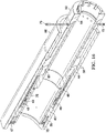
piece coupler assembly 100 is designed to work as a unitized component axially disposed between the top face of thenut 47 and a shoulder on the lockingdog retainer 45 in like fashion with existing big bore running tool features. For instance,FIG. 18 illustrates an existing bigbore running tool 90 with aliner hanger sub-assembly 40 attached onto the bottom of the runningtool 90. In the depicted embodiment, theliner hanger sub-assembly 40 also includes an O-ring 55 located on the outer diameter at the top end. Using the runningtool 90, theliner hanger sub-assembly 40 is inserted into the top end of theliner hanger 88. Theliner hanger sub-assembly 40 is inserted until it is completely engaged with theouter collet mandrel 43 that was previously inserted into the bottom end of theliner hanger 88. A portion of theliner hanger sub-assembly 40 extends beyond the bottom end of thecollet prop mandrel 50 as indicated inFIG. 19 . O-ring 55 is compressed during assembly between theliner hanger sub-assembly 40 and the inside ofouter collet mandrel 43 creating a seal at the interface as shown inFIG. 19 . O-ring 81 is compressed during assembly between theliner hanger sub-assembly 40 and the inside ofcollet prop mandrel 50 creating a seal at the interface as shown inFIG. 19 . -
FIG. 20 illustrates the final components needed to complete installation of theliner hanger 88 to theliner hanger sub-assembly 40. First, a set ofplugs 41 are inserted into the grooved castle turret features at the lower end of thecollet prop mandrel 50 to torque lock it to theliner hanger sub-assembly 40 as illustrated inFIG. 21 . An O-ring 64 is then installed over the set ofplugs 41 to secure the plugs in place as illustrated inFIG. 22 . - A
retainer nut 42 is then threaded onto theliner hanger sub-assembly 40 to secure it to thecollet prop mandrel 50 as shown inFIG. 23 . Finally, a set ofscrews 70 are then installed into theretainer nut 42 to secure it to theliner hanger sub-assembly 40 as illustrated inFIG. 24 . The liner hanger installation is complete at this point. -
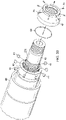
Additional parts 62 may be added to the end of theliner hanger sub-assembly 40 to build up the runningtool 90 as illustrated inFIG. 25 . A cross-sectional view of the completed liner hanger installation ofFIG. 25 is illustrated inFIG. 26 - Accordingly, the above disclosure describes a
coupler assembly 100 that may be used for conveying a single piece liner hanger to a running tool. While the fundamental appearance of the big bore running tool changes little upon first glance, the disclosed embodiments provide several advantages over the current design. One advantage is that it maintains the "modular" design principals first incorporated into the big bore running tool by adapting existing big bore components such as the collet, load transfer sleeve, locking dogs and the upper nut for use with a single piece liner hanger. For instance, using the existing load bearing geometry of the collet is critical given the time and the amount of money spent to validate and proof test many different sized hangers. Additionally, the disclosed embodiments replace a one piece outer collet mandrel with two pieces that form a similar silhouette and accomplish the same task to prop and unprop the collet with respect to the same grooves and mill features but in the new one piece liner hanger body. - Another advantage of the disclosed embodiments is that it offers a means to easily hydro test critical sealing features that previously required expensive test fixtures. In other words, the running tool now has a built in test port for O-ring seal hydro testing, which saves design time and cost. For instance, as described above, two O-rings, instead of one, now form a seal between the collet prop mandrel and the inner diameter of the liner hanger. A pressure port located between the two O-rings communicates to a sealed annular chamber bounded by the inner collet mandrel and the outer collet mandrel sub assembly and O-rings that are placed between the components. The only access to this annular volume is via two threaded communication ports machined perpendicular into the outer diameter of the outer collet mandrel sub assembly at the bottom. These threaded access ports provide a new means to hydro test the O-ring sealing the bore of the liner hanger with the outer collet mandrel sub assembly as well as the two other O-rings that require hydro testing prior to running the tool for a job.
- Moreover, the disclosed embodiments maintain a "Top Down" assembly of the running tool. For example, in accordance with the disclosed embodiments, the collet is inserted from the bottom up keeping sharp edges away from friction reducing coatings on the inner diameter of the liner hanger.
- It should be apparent from the foregoing that the disclosed embodiments have significant advantages over current art. While the embodiments are shown in only a few forms, the embodiments are not limited but are susceptible to various changes and modifications so long as these changes and modifications fall within the scope of the invention as defined in the appended claims.
- As used within the written disclosure and in the claims, the terms "including" and "comprising" are used in an open-ended fashion, and thus should be interpreted to mean "including, but not limited to". Unless otherwise indicated, as used throughout this document, "or" does not require mutual exclusivity. In addition, as used herein, the singular forms "a", "an" and "the" are intended to include the plural forms as well, unless the context clearly indicates otherwise.
Claims (14)
- A method for conveying a single piece liner hanger body (88), the method comprising:assembling an inner sub-assembly portion (43, 44, 45, 46, 47, 48, 49) of a coupler assembly (100) to form an assembled inner sub-assembly portion (43, 44, 45, 46, 47, 48, 49) of the coupler assembly (100);inserting the assembled inner sub-assembly portion (43, 44, 45, 46, 47, 48, 49) of the coupler assembly (100) through a first opening of a single piece liner hanger body (88) until it engages within an inner diameter of the single piece liner hanger body (88), wherein the first opening is intended to be located at the bottom of the single piece liner hanger body (88) when it is situated vertically in a wellbore in use;inserting a collet prop mandrel (50) into the first opening of the single piece liner hanger body (88) until it engages with the assembled inner sub-assembly portion (43, 44, 45, 46, 47, 48, 49) of the coupler assembly (100) to form the coupler assembly (100);inserting a running tool (90) having a liner hanger sub-assembly (40) installed on the bottom of the running tool (90) into a second opening of the single piece liner hanger body (88) until liner hanger sub-assembly (40) engages with the coupler assembly (100), wherein the second opening is intended to be located at the top of the single piece liner hanger body (88) when it is situated vertically in a wellbore in use; andsecuring the liner hanger sub-assembly (40) to the coupler assembly (100).
- The method for conveying a single piece liner hanger body (88) according to claim 1, wherein the assembled inner sub-assembly portion (43, 44, 45, 46, 47, 48, 49) of the coupler assembly (100) comprises:an outer collet mandrel (43) comprising a threaded outer diameter at a first end;a collet (44) positioned radially outwardly over the outer collet mandrel (43), said collet (44) comprising a set of collet fingers (44f) at a first end and a threaded outer diameter at a second end wherein the collet fingers (44f) have a raised edge and further wherein the collet (44) is coupled to the outer collet mandrel (43) via a set of threaded screws (78);a locking dog (48) positioned radially outwardly over the outer collet mandrel (43), said locking dog (48) being next to the second end of the collet (44);a garter spring (49) installed radially outwardly of and onto the locking dog (48);a locking dog retainer (45) positioned radially outwardly over the locking dog (48) and garter spring (49), said locking dog retainer (45) being threaded to the second end of the collet (44);a load transfer sleeve (46) positioned radially outwardly over the locking dog retainer (45) and over the collet (44), said load transfer sleeve (46) abutting the raised edge of the set of collet fingers (44f); anda nut (47) threaded onto the first end of the outer collet mandrel (43).
- The method for conveying a single piece liner hanger body (88) according to claim 2, wherein the step of inserting the assembled inner sub-assembly portion (43, 44, 45, 46, 47, 48, 49) of the coupler assembly (100) comprises inserting the assembled inner sub-assembly portion (43, 44, 45, 46, 47, 48, 49) of the coupler assembly (100) through the first opening of the single piece liner hanger body (88) until the collet (44) on the assembled inner sub-assembly portion (43, 44, 45, 46, 47, 48, 49) of the coupler assembly (100) engages with a matching collet profile within the inner diameter of the liner hanger (88).
- The method for conveying a single piece liner hanger body (88) according to claim 2, wherein the step of inserting the collet prop mandrel (50) comprises inserting the collet prop mandrel (50) into the first opening of the single piece liner hanger body (88) over the outer collet mandrel (43) and until it engages with the collet (44) of the assembled inner sub-assembly portion (43, 44, 45, 46, 47, 48, 49) of the coupler assembly (100) to form the coupler assembly (100).
- The method for conveying a single piece liner hanger body (88) according to claim 4, further comprising securing the collet prop mandrel (50) to the outer collet mandrel (43) of the assembled inner sub-assembly portion (43, 44, 45, 46, 47, 48, 49) of the coupler assembly (100) using a set of threaded hollow plugs (79).
- The method for conveying a single piece liner hanger body (88) according to claim 2, wherein the step of inserting the running tool (90) having the liner hanger sub-assembly (40) installed on the bottom of the running tool (90) comprises inserting the running tool (90) having the liner hanger sub-assembly (40) installed on the bottom of the running tool (90) into the second opening of the single piece liner hanger body (88) until it is completely engaged with the outer collet mandrel (43) of the assembled inner sub-assembly portion (43, 44, 45, 46, 47, 48, 49) of the coupler assembly (100).
- The method for conveying a single piece liner hanger body (88) according to claim 2, wherein securing the liner hanger sub-assembly (40) to the coupler assembly (100) includes securing the liner hanger sub-assembly (40) to the collet prop mandrel (43) using a retainer nut (42).
- The method for conveying a single piece liner hanger body (88) according to claim 2, wherein the step of assembling the inner sub-assembly portion (43, 44, 45, 46, 47, 48, 49) of the coupler assembly (100) to form the assembled inner sub-assembly portion (43, 44, 45, 46, 47, 48, 49) of the coupler assembly (100) comprises:installing the collet (44) over the outer collet mandrel (43) and coupling the collet to the outer collet mandrel with the set of threaded screws (78);installing the locking dog (48) over the outer collet mandrel (43) and next to the collet (44);installing the garter spring (49) onto the locking dog (48);threading the locking dog retainer (45) to the collet (44) at the second end of the collet (44), the locking dog retainer (45) positioned over the locking dog (48) and the garter spring (49);installing the load transfer sleeve (46) to the collet (44), the load transfer sleeve (46) positioned over the locking dog retainer (45); andthreading the nut (47) onto the first end of the outer collet mandrel (43).
- The method for conveying a single piece liner hanger body (88) according to claim 8, further comprising providing an O-ring (58) in an outer diameter of the nut (47) and, during the step of inserting the assembled inner sub-assembly portion (43, 44, 45, 46, 47, 48, 49) of the coupler assembly (100) through the first opening of a single piece liner hanger body (88) until it engages within an inner diameter of the single piece liner hanger body (88), compressing the O-ring (58) between the nut (47) and the single piece liner hanger body (88).
- A coupler assembly (100) for coupling a single piece liner hanger body (88) to a running tool (90), the coupler assembly (100) comprising:an outer collet mandrel (43) comprising a threaded outer diameter at a first end;a collet (44) positioned radially outwardly over the outer collet mandrel (43) said collet (44) comprising a set of collet fingers (44f) at a first end and a threaded outer diameter at a second end wherein the collet fingers (44f) have a raised edge and further wherein the collet (44) is coupled to the outer collet mandrel (43) via a set of threaded screws (78);a locking dog (48) positioned radially outwardly over the collet mandrel (43), said locking dog (48) being next to the second end of the collet (44);a garter spring (49) installed radially outwardly of and onto the locking dog (48);a locking dog retainer (45) positioned radially outwardly over the locking dog (48) and garter spring (49), said locking dog retainer (45) being threaded to the second end of the collet (44);a load transfer sleeve (46) positioned radially outwardly over the locking dog retainer (45) and over the collet (44), said load transfer sleeve (46) abutting the raised edge of the set of collet fingers (44f); anda nut (47) threaded onto the first end of the outer collet mandrel (43).
- The coupler assembly (100) for coupling a single piece liner hanger body (88) to a running tool (90) according to claim 10, wherein the nut (47), the load transfer sleeve (46), the locking dog retainer (45), the garter spring (49), the locking dog (48), the collet (44), and the outer collet mandrel (43) form an inner sub-assembly portion (43, 44, 45, 46, 47, 48, 49) of the coupler assembly (100).
- A system comprising:a single piece liner hanger body (88) having a first opening, wherein the first opening is intended to be located at the bottom of the single piece liner hangar body (88) when it is situated vertically in a wellbore in use;the coupler assembly (100) for coupling a single piece liner hanger body (88) to a running tool (90) according to claim 11, wherein the inner sub-assembly portion (43, 44, 45, 46, 47, 48, 49) of the coupler assembly (100) is insertable through the first opening of the single piece liner hanger body (88) and wherein the coupler assembly further comprises a collet prop mandrel (50) insertable into the first opening of the single piece liner hanger body (88) until it engages with the assembled inner sub-assembly portion (43, 44, 45, 46, 47, 48, 49) of the coupler assembly (100), the collet prop mandrel (50) having mating features for engaging the inner sub-assembly portion (43, 44, 45, 46, 47, 48, 49) of the coupler assembly (100) within the single piece liner hanger body (88);a running tool (90) having a liner hanger sub-assembly (40) installed on the bottom of the running tool (90), the running tool (90) with the liner hanger sub-assembly (40) being insertable into a second opening of the single piece linger hanger body (88), until the liner hangar sub-assembly (40) engages with the coupler assembly (100), wherein the second opening is intended to be located at the top of the single piece liner hanger body (88) when it is situated vertically in a wellbore in use.
- The system according to claim 12, wherein the coupler assembly (100) for coupling a single piece liner hanger body (88) to a running tool (90) further comprises second mating features for engaging the liner hanger sub-assembly (40) attached to the running tool (90).
- The system according to claim 13, further comprising a retaining nut (42) configured to secure the coupler assembly (100) to the liner hanger sub-assembly (40).
Priority Applications (1)
| Application Number | Priority Date | Filing Date | Title |
|---|---|---|---|
| HUE16895676A HUE061650T2 (en) | 2016-03-23 | 2016-03-23 | Big bore running tool quick lock adaptor |
Applications Claiming Priority (1)
| Application Number | Priority Date | Filing Date | Title |
|---|---|---|---|
| PCT/US2016/023812 WO2017164869A1 (en) | 2016-03-23 | 2016-03-23 | Big bore running tool quick lock adaptor |
Publications (3)
| Publication Number | Publication Date |
|---|---|
| EP3400360A1 EP3400360A1 (en) | 2018-11-14 |
| EP3400360A4 EP3400360A4 (en) | 2019-08-21 |
| EP3400360B1 true EP3400360B1 (en) | 2023-01-18 |
Family
ID=59900698
Family Applications (1)
| Application Number | Title | Priority Date | Filing Date |
|---|---|---|---|
| EP16895676.1A Active EP3400360B1 (en) | 2016-03-23 | 2016-03-23 | Big bore running tool quick lock adaptor |
Country Status (15)
| Country | Link |
|---|---|
| US (1) | US10989022B2 (en) |
| EP (1) | EP3400360B1 (en) |
| CN (1) | CN108699894B (en) |
| AU (1) | AU2016398436B2 (en) |
| BR (1) | BR112018016638B1 (en) |
| CA (1) | CA3014985C (en) |
| CO (1) | CO2018008237A2 (en) |
| DE (1) | DE112016006257B4 (en) |
| GB (1) | GB2564272B (en) |
| HU (1) | HUE061650T2 (en) |
| MX (1) | MX2018010158A (en) |
| MY (1) | MY191678A (en) |
| NO (1) | NO20181101A1 (en) |
| SG (1) | SG11201803825PA (en) |
| WO (1) | WO2017164869A1 (en) |
Families Citing this family (3)
| Publication number | Priority date | Publication date | Assignee | Title |
|---|---|---|---|---|
| US10883333B2 (en) * | 2018-05-17 | 2021-01-05 | Weatherford Technology Holdings, Llc | Buoyant system for installing a casing string |
| US10837245B2 (en) | 2018-06-28 | 2020-11-17 | Saudi Arabian Oil Company | Liner hanger system |
| US11927081B2 (en) * | 2022-07-21 | 2024-03-12 | Baker Hughes Oilfield Operations Llc | Liner running tool, method, and system |
Family Cites Families (13)
| Publication number | Priority date | Publication date | Assignee | Title |
|---|---|---|---|---|
| US4311194A (en) * | 1979-08-20 | 1982-01-19 | Otis Engineering Corporation | Liner hanger and running and setting tool |
| US4823881A (en) * | 1988-02-11 | 1989-04-25 | Halliburton Company | Hydraulic setting tool |
| US4862966A (en) | 1988-05-16 | 1989-09-05 | Lindsey Completion Systems, Inc. | Liner hanger with collapsible ball valve seat |
| US4911237A (en) * | 1989-03-16 | 1990-03-27 | Baker Hughes Incorporated | Running tool for liner hanger |
| BR122013000180B1 (en) | 2001-05-18 | 2016-07-19 | Dril Quip Inc | well apparatus |
| US8393389B2 (en) * | 2007-04-20 | 2013-03-12 | Halliburton Evergy Services, Inc. | Running tool for expandable liner hanger and associated methods |
| CN201165866Y (en) * | 2008-03-04 | 2008-12-17 | 北京华油油气技术开发有限公司 | Horizontal well division and combination extracting pipe column |
| CN201428403Y (en) * | 2009-05-30 | 2010-03-24 | 中国石油集团西部钻探工程有限公司克拉玛依钻井工艺研究院 | Under-balance well cementation liner hanger feed tool |
| US8561690B2 (en) | 2011-03-04 | 2013-10-22 | Halliburton Energy Services, Inc. | Expansion cone assembly for setting a liner hanger in a wellbore casing |
| US9500044B2 (en) * | 2011-05-25 | 2016-11-22 | Weatherford Technology Holdings, Llc | Tubular coupling device |
| US9650854B2 (en) * | 2013-05-28 | 2017-05-16 | Weatherford Technology Holdings, Llc | Packoff for liner deployment assembly |
| US20150060086A1 (en) | 2013-09-04 | 2015-03-05 | Halliburton Energy Services, Inc. | Running Tool with Retractable Collet for Liner String Installation in a Wellbore |
| WO2015034489A1 (en) | 2013-09-04 | 2015-03-12 | Halliburton Energy Services, Inc. | Running tool with retractable collet for liner string installation in a wellbore |
-
2016
- 2016-03-23 AU AU2016398436A patent/AU2016398436B2/en active Active
- 2016-03-23 MY MYPI2018702689A patent/MY191678A/en unknown
- 2016-03-23 GB GB1812963.5A patent/GB2564272B/en active Active
- 2016-03-23 SG SG11201803825PA patent/SG11201803825PA/en unknown
- 2016-03-23 MX MX2018010158A patent/MX2018010158A/en unknown
- 2016-03-23 BR BR112018016638-3A patent/BR112018016638B1/en active IP Right Grant
- 2016-03-23 EP EP16895676.1A patent/EP3400360B1/en active Active
- 2016-03-23 DE DE112016006257.5T patent/DE112016006257B4/en active Active
- 2016-03-23 US US15/779,002 patent/US10989022B2/en active Active
- 2016-03-23 WO PCT/US2016/023812 patent/WO2017164869A1/en active Application Filing
- 2016-03-23 CA CA3014985A patent/CA3014985C/en active Active
- 2016-03-23 HU HUE16895676A patent/HUE061650T2/en unknown
- 2016-03-23 CN CN201680081707.7A patent/CN108699894B/en active Active
-
2018
- 2018-08-03 CO CONC2018/0008237A patent/CO2018008237A2/en unknown
- 2018-08-22 NO NO20181101A patent/NO20181101A1/en unknown
Also Published As
| Publication number | Publication date |
|---|---|
| MX2018010158A (en) | 2018-11-09 |
| CN108699894A (en) | 2018-10-23 |
| US20180347323A1 (en) | 2018-12-06 |
| BR112018016638A2 (en) | 2018-12-26 |
| NO20181101A1 (en) | 2018-08-22 |
| CO2018008237A2 (en) | 2018-08-21 |
| SG11201803825PA (en) | 2018-06-28 |
| EP3400360A1 (en) | 2018-11-14 |
| WO2017164869A1 (en) | 2017-09-28 |
| DE112016006257B4 (en) | 2024-01-18 |
| MY191678A (en) | 2022-07-07 |
| US10989022B2 (en) | 2021-04-27 |
| AU2016398436B2 (en) | 2021-11-11 |
| CA3014985C (en) | 2021-06-08 |
| CN108699894B (en) | 2021-03-05 |
| AU2016398436A1 (en) | 2018-05-17 |
| GB2564272A (en) | 2019-01-09 |
| GB2564272B (en) | 2021-06-30 |
| GB201812963D0 (en) | 2018-09-26 |
| EP3400360A4 (en) | 2019-08-21 |
| DE112016006257T5 (en) | 2018-10-04 |
| CA3014985A1 (en) | 2017-09-23 |
| BR112018016638B1 (en) | 2022-09-06 |
| HUE061650T2 (en) | 2023-07-28 |
Similar Documents
| Publication | Publication Date | Title |
|---|---|---|
| US9187963B2 (en) | Low profile clamp for a wellbore tubular | |
| EP1389260B1 (en) | Radially expandable tubular with supported end portion | |
| US8453728B2 (en) | Apparatus and method for depth referencing downhole tubular strings | |
| EP3400360B1 (en) | Big bore running tool quick lock adaptor | |
| US9650875B2 (en) | Liner hanger setting tool and method for use of same | |
| US11352849B2 (en) | Methods and systems for drilling a multilateral well | |
| NO20171958A1 (en) | High-load collet shifting tool | |
| US8215400B2 (en) | System and method for opening a window in a casing string for multilateral wellbore construction | |
| CA2735916C (en) | Narrow well bore | |
| US11585182B1 (en) | Casing head support unit (CHSU) design for life cycle well integrity assurance | |
| US11008817B2 (en) | Aligning two parts of a tubular assembly | |
| US20230399906A1 (en) | Single Trip, Debris Tolerant Lock Mandrel With Equalizing Prong | |
| US20220127912A1 (en) | Sleeved gun connection | |
| GB2602609A (en) | Aligning two parts of a tubular assembly | |
| GB2586965A (en) | Wellhead apparatus, assembly and method for supporting downhole tubing |
Legal Events
| Date | Code | Title | Description |
|---|---|---|---|
| STAA | Information on the status of an ep patent application or granted ep patent |
Free format text: STATUS: THE INTERNATIONAL PUBLICATION HAS BEEN MADE |
|
| PUAI | Public reference made under article 153(3) epc to a published international application that has entered the european phase |
Free format text: ORIGINAL CODE: 0009012 |
|
| STAA | Information on the status of an ep patent application or granted ep patent |
Free format text: STATUS: REQUEST FOR EXAMINATION WAS MADE |
|
| 17P | Request for examination filed |
Effective date: 20180809 |
|
| AK | Designated contracting states |
Kind code of ref document: A1 Designated state(s): AL AT BE BG CH CY CZ DE DK EE ES FI FR GB GR HR HU IE IS IT LI LT LU LV MC MK MT NL NO PL PT RO RS SE SI SK SM TR |
|
| AX | Request for extension of the european patent |
Extension state: BA ME |
|
| DAV | Request for validation of the european patent (deleted) | ||
| DAX | Request for extension of the european patent (deleted) | ||
| REG | Reference to a national code |
Ref country code: DE Ref legal event code: R079 Ref document number: 602016077566 Country of ref document: DE Free format text: PREVIOUS MAIN CLASS: E21B0017020000 Ipc: E21B0043100000 |
|
| A4 | Supplementary search report drawn up and despatched |
Effective date: 20190719 |
|
| RIC1 | Information provided on ipc code assigned before grant |
Ipc: E21B 23/00 20060101ALI20190715BHEP Ipc: E21B 43/10 20060101AFI20190715BHEP |
|
| STAA | Information on the status of an ep patent application or granted ep patent |
Free format text: STATUS: EXAMINATION IS IN PROGRESS |
|
| 17Q | First examination report despatched |
Effective date: 20200304 |
|
| STAA | Information on the status of an ep patent application or granted ep patent |
Free format text: STATUS: EXAMINATION IS IN PROGRESS |
|
| RBV | Designated contracting states (corrected) |
Designated state(s): AL AT BE BG CH CY CZ DE DK EE ES FI FR GR HR HU IE IS IT LI LT LU LV MC MK MT NL NO PL PT RO RS SE SI SK SM TR |
|
| GRAP | Despatch of communication of intention to grant a patent |
Free format text: ORIGINAL CODE: EPIDOSNIGR1 |
|
| STAA | Information on the status of an ep patent application or granted ep patent |
Free format text: STATUS: GRANT OF PATENT IS INTENDED |
|
| INTG | Intention to grant announced |
Effective date: 20221021 |
|
| GRAS | Grant fee paid |
Free format text: ORIGINAL CODE: EPIDOSNIGR3 |
|
| GRAA | (expected) grant |
Free format text: ORIGINAL CODE: 0009210 |
|
| STAA | Information on the status of an ep patent application or granted ep patent |
Free format text: STATUS: THE PATENT HAS BEEN GRANTED |
|
| AK | Designated contracting states |
Kind code of ref document: B1 Designated state(s): AL AT BE BG CH CY CZ DE DK EE ES FI FR GR HR HU IE IS IT LI LT LU LV MC MK MT NL NO PL PT RO RS SE SI SK SM TR |
|
| REG | Reference to a national code |
Ref country code: DE Ref legal event code: R096 Ref document number: 602016077566 Country of ref document: DE |
|
| REG | Reference to a national code |
Ref country code: CH Ref legal event code: EP |
|
| REG | Reference to a national code |
Ref country code: AT Ref legal event code: REF Ref document number: 1544813 Country of ref document: AT Kind code of ref document: T Effective date: 20230215 Ref country code: IE Ref legal event code: FG4D |
|
| REG | Reference to a national code |
Ref country code: RO Ref legal event code: EPE |
|
| REG | Reference to a national code |
Ref country code: NL Ref legal event code: FP |
|
| PGFP | Annual fee paid to national office [announced via postgrant information from national office to epo] |
Ref country code: RO Payment date: 20230328 Year of fee payment: 8 |
|
| REG | Reference to a national code |
Ref country code: LT Ref legal event code: MG9D |
|
| REG | Reference to a national code |
Ref country code: AT Ref legal event code: MK05 Ref document number: 1544813 Country of ref document: AT Kind code of ref document: T Effective date: 20230118 |
|
| PGFP | Annual fee paid to national office [announced via postgrant information from national office to epo] |
Ref country code: NL Payment date: 20230321 Year of fee payment: 8 |
|
| P01 | Opt-out of the competence of the unified patent court (upc) registered |
Effective date: 20230530 |
|
| REG | Reference to a national code |
Ref country code: HU Ref legal event code: AG4A Ref document number: E061650 Country of ref document: HU |
|
| PG25 | Lapsed in a contracting state [announced via postgrant information from national office to epo] |
Ref country code: RS Free format text: LAPSE BECAUSE OF FAILURE TO SUBMIT A TRANSLATION OF THE DESCRIPTION OR TO PAY THE FEE WITHIN THE PRESCRIBED TIME-LIMIT Effective date: 20230118 Ref country code: PT Free format text: LAPSE BECAUSE OF FAILURE TO SUBMIT A TRANSLATION OF THE DESCRIPTION OR TO PAY THE FEE WITHIN THE PRESCRIBED TIME-LIMIT Effective date: 20230518 Ref country code: NO Free format text: LAPSE BECAUSE OF FAILURE TO SUBMIT A TRANSLATION OF THE DESCRIPTION OR TO PAY THE FEE WITHIN THE PRESCRIBED TIME-LIMIT Effective date: 20230418 Ref country code: LV Free format text: LAPSE BECAUSE OF FAILURE TO SUBMIT A TRANSLATION OF THE DESCRIPTION OR TO PAY THE FEE WITHIN THE PRESCRIBED TIME-LIMIT Effective date: 20230118 Ref country code: LT Free format text: LAPSE BECAUSE OF FAILURE TO SUBMIT A TRANSLATION OF THE DESCRIPTION OR TO PAY THE FEE WITHIN THE PRESCRIBED TIME-LIMIT Effective date: 20230118 Ref country code: HR Free format text: LAPSE BECAUSE OF FAILURE TO SUBMIT A TRANSLATION OF THE DESCRIPTION OR TO PAY THE FEE WITHIN THE PRESCRIBED TIME-LIMIT Effective date: 20230118 Ref country code: ES Free format text: LAPSE BECAUSE OF FAILURE TO SUBMIT A TRANSLATION OF THE DESCRIPTION OR TO PAY THE FEE WITHIN THE PRESCRIBED TIME-LIMIT Effective date: 20230118 Ref country code: AT Free format text: LAPSE BECAUSE OF FAILURE TO SUBMIT A TRANSLATION OF THE DESCRIPTION OR TO PAY THE FEE WITHIN THE PRESCRIBED TIME-LIMIT Effective date: 20230118 |
|
| PG25 | Lapsed in a contracting state [announced via postgrant information from national office to epo] |
Ref country code: SE Free format text: LAPSE BECAUSE OF FAILURE TO SUBMIT A TRANSLATION OF THE DESCRIPTION OR TO PAY THE FEE WITHIN THE PRESCRIBED TIME-LIMIT Effective date: 20230118 Ref country code: PL Free format text: LAPSE BECAUSE OF FAILURE TO SUBMIT A TRANSLATION OF THE DESCRIPTION OR TO PAY THE FEE WITHIN THE PRESCRIBED TIME-LIMIT Effective date: 20230118 Ref country code: IS Free format text: LAPSE BECAUSE OF FAILURE TO SUBMIT A TRANSLATION OF THE DESCRIPTION OR TO PAY THE FEE WITHIN THE PRESCRIBED TIME-LIMIT Effective date: 20230518 Ref country code: GR Free format text: LAPSE BECAUSE OF FAILURE TO SUBMIT A TRANSLATION OF THE DESCRIPTION OR TO PAY THE FEE WITHIN THE PRESCRIBED TIME-LIMIT Effective date: 20230419 Ref country code: FI Free format text: LAPSE BECAUSE OF FAILURE TO SUBMIT A TRANSLATION OF THE DESCRIPTION OR TO PAY THE FEE WITHIN THE PRESCRIBED TIME-LIMIT Effective date: 20230118 |
|
| PGFP | Annual fee paid to national office [announced via postgrant information from national office to epo] |
Ref country code: HU Payment date: 20230329 Year of fee payment: 8 |
|
| REG | Reference to a national code |
Ref country code: DE Ref legal event code: R119 Ref document number: 602016077566 Country of ref document: DE |
|
| PG25 | Lapsed in a contracting state [announced via postgrant information from national office to epo] |
Ref country code: SM Free format text: LAPSE BECAUSE OF FAILURE TO SUBMIT A TRANSLATION OF THE DESCRIPTION OR TO PAY THE FEE WITHIN THE PRESCRIBED TIME-LIMIT Effective date: 20230118 Ref country code: MC Free format text: LAPSE BECAUSE OF FAILURE TO SUBMIT A TRANSLATION OF THE DESCRIPTION OR TO PAY THE FEE WITHIN THE PRESCRIBED TIME-LIMIT Effective date: 20230118 Ref country code: EE Free format text: LAPSE BECAUSE OF FAILURE TO SUBMIT A TRANSLATION OF THE DESCRIPTION OR TO PAY THE FEE WITHIN THE PRESCRIBED TIME-LIMIT Effective date: 20230118 Ref country code: DK Free format text: LAPSE BECAUSE OF FAILURE TO SUBMIT A TRANSLATION OF THE DESCRIPTION OR TO PAY THE FEE WITHIN THE PRESCRIBED TIME-LIMIT Effective date: 20230118 Ref country code: CZ Free format text: LAPSE BECAUSE OF FAILURE TO SUBMIT A TRANSLATION OF THE DESCRIPTION OR TO PAY THE FEE WITHIN THE PRESCRIBED TIME-LIMIT Effective date: 20230118 |
|
| REG | Reference to a national code |
Ref country code: CH Ref legal event code: PL |
|
| PLBE | No opposition filed within time limit |
Free format text: ORIGINAL CODE: 0009261 |
|
| STAA | Information on the status of an ep patent application or granted ep patent |
Free format text: STATUS: NO OPPOSITION FILED WITHIN TIME LIMIT |
|
| PG25 | Lapsed in a contracting state [announced via postgrant information from national office to epo] |
Ref country code: SK Free format text: LAPSE BECAUSE OF FAILURE TO SUBMIT A TRANSLATION OF THE DESCRIPTION OR TO PAY THE FEE WITHIN THE PRESCRIBED TIME-LIMIT Effective date: 20230118 |
|
| REG | Reference to a national code |
Ref country code: BE Ref legal event code: MM Effective date: 20230331 |
|
| 26N | No opposition filed |
Effective date: 20231019 |
|
| PG25 | Lapsed in a contracting state [announced via postgrant information from national office to epo] |
Ref country code: LU Free format text: LAPSE BECAUSE OF NON-PAYMENT OF DUE FEES Effective date: 20230323 |
|
| REG | Reference to a national code |
Ref country code: IE Ref legal event code: MM4A |
|
| PG25 | Lapsed in a contracting state [announced via postgrant information from national office to epo] |
Ref country code: SI Free format text: LAPSE BECAUSE OF FAILURE TO SUBMIT A TRANSLATION OF THE DESCRIPTION OR TO PAY THE FEE WITHIN THE PRESCRIBED TIME-LIMIT Effective date: 20230118 Ref country code: LI Free format text: LAPSE BECAUSE OF NON-PAYMENT OF DUE FEES Effective date: 20230331 Ref country code: IE Free format text: LAPSE BECAUSE OF NON-PAYMENT OF DUE FEES Effective date: 20230323 Ref country code: FR Free format text: LAPSE BECAUSE OF NON-PAYMENT OF DUE FEES Effective date: 20230331 Ref country code: DE Free format text: LAPSE BECAUSE OF NON-PAYMENT OF DUE FEES Effective date: 20231003 Ref country code: CH Free format text: LAPSE BECAUSE OF NON-PAYMENT OF DUE FEES Effective date: 20230331 |
|
| PG25 | Lapsed in a contracting state [announced via postgrant information from national office to epo] |
Ref country code: BE Free format text: LAPSE BECAUSE OF NON-PAYMENT OF DUE FEES Effective date: 20230331 |