EP3400324B1 - Method for producing a corrosion resistant metal substrate and corrosion resistant metal substrate provided thereby - Google Patents
Method for producing a corrosion resistant metal substrate and corrosion resistant metal substrate provided thereby Download PDFInfo
- Publication number
- EP3400324B1 EP3400324B1 EP17700205.2A EP17700205A EP3400324B1 EP 3400324 B1 EP3400324 B1 EP 3400324B1 EP 17700205 A EP17700205 A EP 17700205A EP 3400324 B1 EP3400324 B1 EP 3400324B1
- Authority
- EP
- European Patent Office
- Prior art keywords
- nickel
- substrate
- layer
- molybdenum
- molybdenum oxide
- Prior art date
- Legal status (The legal status is an assumption and is not a legal conclusion. Google has not performed a legal analysis and makes no representation as to the accuracy of the status listed.)
- Active
Links
Images

Classifications
-
- C—CHEMISTRY; METALLURGY
- C25—ELECTROLYTIC OR ELECTROPHORETIC PROCESSES; APPARATUS THEREFOR
- C25D—PROCESSES FOR THE ELECTROLYTIC OR ELECTROPHORETIC PRODUCTION OF COATINGS; ELECTROFORMING; APPARATUS THEREFOR
- C25D5/00—Electroplating characterised by the process; Pretreatment or after-treatment of workpieces
- C25D5/627—Electroplating characterised by the visual appearance of the layers, e.g. colour, brightness or mat appearance
-
- C—CHEMISTRY; METALLURGY
- C21—METALLURGY OF IRON
- C21D—MODIFYING THE PHYSICAL STRUCTURE OF FERROUS METALS; GENERAL DEVICES FOR HEAT TREATMENT OF FERROUS OR NON-FERROUS METALS OR ALLOYS; MAKING METAL MALLEABLE, e.g. BY DECARBURISATION OR TEMPERING
- C21D1/00—General methods or devices for heat treatment, e.g. annealing, hardening, quenching or tempering
- C21D1/26—Methods of annealing
-
- C—CHEMISTRY; METALLURGY
- C21—METALLURGY OF IRON
- C21D—MODIFYING THE PHYSICAL STRUCTURE OF FERROUS METALS; GENERAL DEVICES FOR HEAT TREATMENT OF FERROUS OR NON-FERROUS METALS OR ALLOYS; MAKING METAL MALLEABLE, e.g. BY DECARBURISATION OR TEMPERING
- C21D9/00—Heat treatment, e.g. annealing, hardening, quenching or tempering, adapted for particular articles; Furnaces therefor
- C21D9/52—Heat treatment, e.g. annealing, hardening, quenching or tempering, adapted for particular articles; Furnaces therefor for wires; for strips ; for rods of unlimited length
-
- C—CHEMISTRY; METALLURGY
- C22—METALLURGY; FERROUS OR NON-FERROUS ALLOYS; TREATMENT OF ALLOYS OR NON-FERROUS METALS
- C22F—CHANGING THE PHYSICAL STRUCTURE OF NON-FERROUS METALS AND NON-FERROUS ALLOYS
- C22F1/00—Changing the physical structure of non-ferrous metals or alloys by heat treatment or by hot or cold working
- C22F1/04—Changing the physical structure of non-ferrous metals or alloys by heat treatment or by hot or cold working of aluminium or alloys based thereon
-
- C—CHEMISTRY; METALLURGY
- C25—ELECTROLYTIC OR ELECTROPHORETIC PROCESSES; APPARATUS THEREFOR
- C25D—PROCESSES FOR THE ELECTROLYTIC OR ELECTROPHORETIC PRODUCTION OF COATINGS; ELECTROFORMING; APPARATUS THEREFOR
- C25D3/00—Electroplating: Baths therefor
- C25D3/02—Electroplating: Baths therefor from solutions
- C25D3/12—Electroplating: Baths therefor from solutions of nickel or cobalt
-
- C—CHEMISTRY; METALLURGY
- C25—ELECTROLYTIC OR ELECTROPHORETIC PROCESSES; APPARATUS THEREFOR
- C25D—PROCESSES FOR THE ELECTROLYTIC OR ELECTROPHORETIC PRODUCTION OF COATINGS; ELECTROFORMING; APPARATUS THEREFOR
- C25D5/00—Electroplating characterised by the process; Pretreatment or after-treatment of workpieces
- C25D5/10—Electroplating with more than one layer of the same or of different metals
- C25D5/12—Electroplating with more than one layer of the same or of different metals at least one layer being of nickel or chromium
-
- C—CHEMISTRY; METALLURGY
- C25—ELECTROLYTIC OR ELECTROPHORETIC PROCESSES; APPARATUS THEREFOR
- C25D—PROCESSES FOR THE ELECTROLYTIC OR ELECTROPHORETIC PRODUCTION OF COATINGS; ELECTROFORMING; APPARATUS THEREFOR
- C25D5/00—Electroplating characterised by the process; Pretreatment or after-treatment of workpieces
- C25D5/34—Pretreatment of metallic surfaces to be electroplated
- C25D5/36—Pretreatment of metallic surfaces to be electroplated of iron or steel
-
- C—CHEMISTRY; METALLURGY
- C25—ELECTROLYTIC OR ELECTROPHORETIC PROCESSES; APPARATUS THEREFOR
- C25D—PROCESSES FOR THE ELECTROLYTIC OR ELECTROPHORETIC PRODUCTION OF COATINGS; ELECTROFORMING; APPARATUS THEREFOR
- C25D5/00—Electroplating characterised by the process; Pretreatment or after-treatment of workpieces
- C25D5/34—Pretreatment of metallic surfaces to be electroplated
- C25D5/42—Pretreatment of metallic surfaces to be electroplated of light metals
- C25D5/44—Aluminium
-
- C—CHEMISTRY; METALLURGY
- C25—ELECTROLYTIC OR ELECTROPHORETIC PROCESSES; APPARATUS THEREFOR
- C25D—PROCESSES FOR THE ELECTROLYTIC OR ELECTROPHORETIC PRODUCTION OF COATINGS; ELECTROFORMING; APPARATUS THEREFOR
- C25D5/00—Electroplating characterised by the process; Pretreatment or after-treatment of workpieces
- C25D5/48—After-treatment of electroplated surfaces
- C25D5/50—After-treatment of electroplated surfaces by heat-treatment
-
- C—CHEMISTRY; METALLURGY
- C25—ELECTROLYTIC OR ELECTROPHORETIC PROCESSES; APPARATUS THEREFOR
- C25D—PROCESSES FOR THE ELECTROLYTIC OR ELECTROPHORETIC PRODUCTION OF COATINGS; ELECTROFORMING; APPARATUS THEREFOR
- C25D5/00—Electroplating characterised by the process; Pretreatment or after-treatment of workpieces
- C25D5/60—Electroplating characterised by the structure or texture of the layers
- C25D5/623—Porosity of the layers
-
- C—CHEMISTRY; METALLURGY
- C25—ELECTROLYTIC OR ELECTROPHORETIC PROCESSES; APPARATUS THEREFOR
- C25D—PROCESSES FOR THE ELECTROLYTIC OR ELECTROPHORETIC PRODUCTION OF COATINGS; ELECTROFORMING; APPARATUS THEREFOR
- C25D9/00—Electrolytic coating other than with metals
- C25D9/04—Electrolytic coating other than with metals with inorganic materials
- C25D9/08—Electrolytic coating other than with metals with inorganic materials by cathodic processes
- C25D9/10—Electrolytic coating other than with metals with inorganic materials by cathodic processes on iron or steel
-
- C—CHEMISTRY; METALLURGY
- C25—ELECTROLYTIC OR ELECTROPHORETIC PROCESSES; APPARATUS THEREFOR
- C25D—PROCESSES FOR THE ELECTROLYTIC OR ELECTROPHORETIC PRODUCTION OF COATINGS; ELECTROFORMING; APPARATUS THEREFOR
- C25D9/00—Electrolytic coating other than with metals
- C25D9/04—Electrolytic coating other than with metals with inorganic materials
- C25D9/08—Electrolytic coating other than with metals with inorganic materials by cathodic processes
- C25D9/12—Electrolytic coating other than with metals with inorganic materials by cathodic processes on light metals
-
- F—MECHANICAL ENGINEERING; LIGHTING; HEATING; WEAPONS; BLASTING
- F01—MACHINES OR ENGINES IN GENERAL; ENGINE PLANTS IN GENERAL; STEAM ENGINES
- F01N—GAS-FLOW SILENCERS OR EXHAUST APPARATUS FOR MACHINES OR ENGINES IN GENERAL; GAS-FLOW SILENCERS OR EXHAUST APPARATUS FOR INTERNAL-COMBUSTION ENGINES
- F01N13/00—Exhaust or silencing apparatus characterised by constructional features
- F01N13/16—Selection of particular materials
-
- F—MECHANICAL ENGINEERING; LIGHTING; HEATING; WEAPONS; BLASTING
- F01—MACHINES OR ENGINES IN GENERAL; ENGINE PLANTS IN GENERAL; STEAM ENGINES
- F01N—GAS-FLOW SILENCERS OR EXHAUST APPARATUS FOR MACHINES OR ENGINES IN GENERAL; GAS-FLOW SILENCERS OR EXHAUST APPARATUS FOR INTERNAL-COMBUSTION ENGINES
- F01N3/00—Exhaust or silencing apparatus having means for purifying, rendering innocuous, or otherwise treating exhaust
- F01N3/08—Exhaust or silencing apparatus having means for purifying, rendering innocuous, or otherwise treating exhaust for rendering innocuous
- F01N3/10—Exhaust or silencing apparatus having means for purifying, rendering innocuous, or otherwise treating exhaust for rendering innocuous by thermal or catalytic conversion of noxious components of exhaust
- F01N3/24—Exhaust or silencing apparatus having means for purifying, rendering innocuous, or otherwise treating exhaust for rendering innocuous by thermal or catalytic conversion of noxious components of exhaust characterised by constructional aspects of converting apparatus
- F01N3/28—Construction of catalytic reactors
- F01N3/2803—Construction of catalytic reactors characterised by structure, by material or by manufacturing of catalyst support
- F01N3/2807—Metal other than sintered metal
- F01N3/281—Metallic honeycomb monoliths made of stacked or rolled sheets, foils or plates
-
- F—MECHANICAL ENGINEERING; LIGHTING; HEATING; WEAPONS; BLASTING
- F02—COMBUSTION ENGINES; HOT-GAS OR COMBUSTION-PRODUCT ENGINE PLANTS
- F02M—SUPPLYING COMBUSTION ENGINES IN GENERAL WITH COMBUSTIBLE MIXTURES OR CONSTITUENTS THEREOF
- F02M37/00—Apparatus or systems for feeding liquid fuel from storage containers to carburettors or fuel-injection apparatus; Arrangements for purifying liquid fuel specially adapted for, or arranged on, internal-combustion engines
- F02M37/0011—Constructional details; Manufacturing or assembly of elements of fuel systems; Materials therefor
- F02M37/0017—Constructional details; Manufacturing or assembly of elements of fuel systems; Materials therefor related to fuel pipes or their connections, e.g. joints or sealings
-
- F—MECHANICAL ENGINEERING; LIGHTING; HEATING; WEAPONS; BLASTING
- F01—MACHINES OR ENGINES IN GENERAL; ENGINE PLANTS IN GENERAL; STEAM ENGINES
- F01N—GAS-FLOW SILENCERS OR EXHAUST APPARATUS FOR MACHINES OR ENGINES IN GENERAL; GAS-FLOW SILENCERS OR EXHAUST APPARATUS FOR INTERNAL-COMBUSTION ENGINES
- F01N2510/00—Surface coverings
- F01N2510/08—Surface coverings for corrosion prevention
-
- F—MECHANICAL ENGINEERING; LIGHTING; HEATING; WEAPONS; BLASTING
- F01—MACHINES OR ENGINES IN GENERAL; ENGINE PLANTS IN GENERAL; STEAM ENGINES
- F01N—GAS-FLOW SILENCERS OR EXHAUST APPARATUS FOR MACHINES OR ENGINES IN GENERAL; GAS-FLOW SILENCERS OR EXHAUST APPARATUS FOR INTERNAL-COMBUSTION ENGINES
- F01N2530/00—Selection of materials for tubes, chambers or housings
- F01N2530/02—Corrosion resistive metals
-
- F—MECHANICAL ENGINEERING; LIGHTING; HEATING; WEAPONS; BLASTING
- F01—MACHINES OR ENGINES IN GENERAL; ENGINE PLANTS IN GENERAL; STEAM ENGINES
- F01N—GAS-FLOW SILENCERS OR EXHAUST APPARATUS FOR MACHINES OR ENGINES IN GENERAL; GAS-FLOW SILENCERS OR EXHAUST APPARATUS FOR INTERNAL-COMBUSTION ENGINES
- F01N2530/00—Selection of materials for tubes, chambers or housings
- F01N2530/02—Corrosion resistive metals
- F01N2530/04—Steel alloys, e.g. stainless steel
-
- F—MECHANICAL ENGINEERING; LIGHTING; HEATING; WEAPONS; BLASTING
- F01—MACHINES OR ENGINES IN GENERAL; ENGINE PLANTS IN GENERAL; STEAM ENGINES
- F01N—GAS-FLOW SILENCERS OR EXHAUST APPARATUS FOR MACHINES OR ENGINES IN GENERAL; GAS-FLOW SILENCERS OR EXHAUST APPARATUS FOR INTERNAL-COMBUSTION ENGINES
- F01N2530/00—Selection of materials for tubes, chambers or housings
- F01N2530/06—Aluminium or alloys thereof
Definitions
- This invention relates to a method for producing a corrosion resistant metal substrate and corrosion resistant metal substrate provided thereby.
- Materials used for exhaust piping, mufflers, and other exhaust system components consist mainly of ferrous alloys. Aluminium alloys are sometimes used as a coating on ferrous alloys to impart additional corrosion resistance.
- the choice of exhaust system materials is driven by a number of factors including cost, warranty requirements and legislated and customer demands for long service life.
- Mild carbon steel was the material of choice for exhaust systems for many decades.
- An iron oxide coating on the exhaust system protected it from atmospheric corrosion to varying degrees. However, it suffered from poor corrosion resistance when exposed to road salt and exhaust condensate. As a result, exhaust systems made from this material had a very short life if exposed to the environment experienced by many on-road vehicles.
- the corrosion resistance of carbon steel can be greatly improved through the use of a hot dipped aluminium coating. This is often referred to as aluminised steel.
- One particularly important ferrous alloy alloying element is chromium.
- stainless steel By adding sufficient chromium, stainless steel is formed. When stainless steel is heated, chromium forms a protective chromium oxide coating that delays further oxidation. A minimum of about 10.5% chromium is usually required to passivate the surface and to classify a material as stainless steel. So long as this oxide layer is stable and continuous, the metal substrate is well protected from corrosion. Since about the mid-1990s, plain carbon and low alloy steels have been replaced by stainless steel as the primary material for exhaust systems. This transition has taken place because of market demands for extended warranties, and because of demands mandated by emission standards. Technologies to meet increasingly stringent emission standards can raise exhaust temperatures which makes the task of meeting strength and durability requirements especially challenging. Emission standards also require that exhaust systems are designed in a manner that facilitates leak-free assembly, installation and operation for the full useful life of the vehicle.
- US2010/0167087 discloses a steel or aluminum substrate electroplated with a corrosion resistant alloy layer of Ni-Mo.
- One or more of the objects is reached by a method for producing a corrosion resistant metal substrate by electroplating:
- the diffusion layer contains nickel, molybdenum and optionally cobalt. There may be other components in the diffusion layer such as phosphate.
- the metal substrate which may be provided in the form of a coiled strip of steel such as (low) carbon steel or stainless steel, or in the form a coiled strip of aluminium or aluminium alloy with a suitable chemical composition for the application of the final product, is provided with a nickel layer, or a nickel-based layer, and optionally with a cobalt layer on top of the nickel or nickel-based layer to form a plated substrate.
- Nickel layers can for instance be deposited onto the substrate in a Watts nickel plating bath.
- a nickel-based layer is a layer predominantly consisting of nickel but not solely of nickel.
- a nickel alloy layer is therefore considered a nickel based layer.
- the term "nickel layer" hereinafter intends to include "nickel-based layer".
- the corrosion protection offered by the nickel layer may be insufficient for certain applications as a result of the presence of pores in the nickel layer.
- the cobalt layer is used to improve the corrosion resistance of the nickel plated substrate.
- the plated substrate is then led through the said aqueous solution in an electroplating device in which the plated substrate acts as the cathode, and provided with the molybdenum oxide layer.
- the molybdenum oxide in the molybdenum oxide layer is then reduced to molybdenum metal in a reduction annealing step and, as a consequence of the high temperature during the reduction annealing step, the molybdenum diffuses into the nickel and/or cobalt layer, thereby forming a diffusion layer comprising nickel, molybdenum and optionally cobalt.
- the reduction annealing step is also the diffusion annealing step. This is the preferable case. However, if necessary, the annealing step can be prolonged to further promote the diffusion after the reduction of the molybdenum oxide has been completed.
- the reducing atmosphere is a hydrogen containing atmosphere, such as substantially pure hydrogen or HNX.
- the diffusion layer comprising nickel and molybdenum, and optionally cobalt, is pore free, and provides an excellent protection of the substrate.
- the molybdenum salt is ammonium molybdate ((NH 4 ) 6 Mo 7 O 24 ).
- ammonium molybdate (NH 4 ) 6 Mo 7 O 24 ).
- ammonium molybdate (NH 4 ) 6 Mo 7 O 24 ).
- ammonium molybdate (NH 4 ) 6 Mo 7 O 24 ).
- Other molybdenum salts would result in deposits on the surface.
- sodium-molybdate would result in the presence of sodium on the surface which would result in an undesirable alkaline corrosion reaction.
- the phosphate is sodium dihydrogen phosphate (NaH 2 PO 4 ).
- NaH 2 PO 4 sodium dihydrogen phosphate
- This functions acts both a conducting salt in the electrolyte and as a buffer salt.
- the buffer ensures that the right pH-value of the electrolyte is maintained.
- Potassium dihydrogen phosphate (KH 2 PO 4 ) could technically also be used, alone or as a mixture with NaH 2 PO 4 , but KH 2 PO 4 is currently more expensive and therefore economically less attractive.
- the nickel layer (or nickel-based layer) provided on the substrate is between 0.5 and 5 ⁇ m in thickness. This thickness range provides sufficient thickness for the diffusion layer after the reduction annealing to be effective. It is preferable that the diffusion layer comprising of nickel, originating from the nickel or nickel-based layer, and optionally cobalt, originating from the optional cobalt layer, and molybdenum, originating from the reduced molybdenum oxide layer, has a thickness of between 10 and 200 nm. A preferable minimum thickness is 20 nm, and a preferable maximum thickness is 150 nm. Preferably the thickness of the diffusion layer is between 50 and 100 nm.
- the temperature of the aqueous solution is at least 51 °C and/or at most 69 °C.
- the plating time is preferably at most 20 seconds, whereas it is preferable that the current density for the electrodeposition of the molybdenum oxide layer is at least 6 and/or at most 22 A/dm 2 . More preferably the temperature of the aqueous solution is at least 55 °C and/or at most 65 °C.
- the maximum annealing temperature is 700 °C, preferably 650 °C and more preferably 600 °C to prevent too large an impact on the properties of the steel substrate.
- the maximum annealing temperature is 900 °C, preferably 850 °C and more preferably 800 °C to prevent too large an impact on the properties of the steel substrate.
- the lower limit of the annealing temperature is controlled largely by the lay-out of the annealing facilities and of the economy of the process. The lower the temperature, the longer it takes for a Ni-Mo-diffusion layer of a desired thickness to form.
- the allowable temperatures are lower.
- the maximum annealing temperature depends on the alloy is at most 500 and preferably at most 450 °C to prevent too large an impact on the properties of the substrate.
- a suitable temperature can be determined easily by simple trial and error. As the temperature is lower, the required diffusion time increases.
- the annealing time in the batch annealing process is between 6 and 10 hours, preferably at most 8.5 hours and more preferably at most 7.5 hours.
- the annealing time is at most 120 seconds, preferably at most 95 s, more preferably at most 75 s and even more preferably at most 40 s.
- a suitable minimum continuous annealing temperature is 5 s, preferably at least 10 s.
- This composition allows to effectively and reproducibly deposit the molybdenum oxide layer. It is noted that 30 g/l of (NH 4 ) 6 Mo 7 O 24 corresponds to 0.024 mol/l and 50 g/l of NaH 2 PO 4 to 0.42 mol/l.
- the thickness of the deposited molybdenum oxide layer is at most 100 nm, preferably at most 75, more preferably 50 nm, and even more preferably 40 nm.
- the minimum thickness is at least 10 nm.
- the pH of the aqueous solution is at least 4.5 and/or at most 6.
- the pH is at least 5.25 and/or at most 5.75.
- the cathodic current density for depositing the molybdenum oxide layer is at least 12.5 A/dm 2 and preferably at least 15 A/dm 2 .
- the steel substrate is a carbon steel, preferably a low carbon steel, extra-low carbon steel or a HSLA-steel.
- These unalloyed (LC and ELC) or micro-alloyed (HSLA) steels are relatively cheap substrates and provide good strength and formability.
- the steels are produced by means of commonly known processes such as casting, hot-rolling and cold-rolling.
- Low carbon steels typically comprise 0.05 to 0.15 wt.% C and extra low carbon steels typically comprise 0.02 to 0.05 wt.% C.
- Other elements may be present in addition to carbon in accordance with EN 10020-2000 which prescribes how much of a certain element may be present to still be considered an unalloyed steel.
- High-strength low-alloy (HSLA) steels are designed to provide better mechanical properties and/or greater resistance to atmospheric corrosion than carbon steels.
- the HSLA steels have low carbon contents (0.05-0.15% C) in order to produce adequate formability and weldability, and they have manganese contents up to 2.0%.
- Small quantities of chromium, nickel, molybdenum, copper, nitrogen, vanadium, niobium, titanium and zirconium are used in various combinations to achieve the desired properties.
- the steel substrate has been cold-rolled to its final thickness, usually between 0.15 and 1.5 mm, and the cold-rolled steel substrate may or may not have been recrystallisation or recovery annealed prior to depositing the nickel and optional cobalt layer according to the invention.
- the steel substrate is preferably supplied in the form of a coiled strip.
- the steel substrate is a ferritic stainless steel, such as an SAE 400-series, which generally are considered to have better engineering properties than austenitic stainless steel grades, but have reduced corrosion resistance, because of the lower chromium and nickel content. They are also usually less expensive. Ferritic stainless steels have a body-centered cubic crystal structure and contain between 10.5% and 27% chromium with very little nickel, if any. By means of a non-limiting example the steel SAE 430 (1.4016) proved to be a useful substrate for the method according to the invention.
- the stainless steel substrate has been cold-rolled to its final thickness, usually between 0.15 and 1.5 mm, and the cold-rolled steel substrate may or may not have been recrystallisation or recovery annealed prior to depositing the nickel and optional cobalt layer according to the invention.
- the stainless steel substrate is preferably supplied in the form of a coiled strip.
- the substrate for the method according to the invention may also be an aluminium or an aluminium alloy substrate.
- the diffusion layer comprising of nickel originating from the nickel or nickel-based layer and molybdenum originating from the molybdenum oxide layer also comprises phosphor, preferably 5 to 15 wt.% of phosphor, more preferably 6 to 13 wt.%. A suitable maximum amount is 10 wt.%. A suitable minimum amount is 7 wt.%.
- the invention is also embodied in a corrosion resistant metal substrate provided with a diffusion layer comprising nickel, molybdenum and optionally cobalt, produced according to the invention wherein the diffusion layer (i.e. the Ni-Mo- or Ni-Mo-Co-diffusion layer) has a thickness of between 10 and 200 nm.
- the diffusion layer i.e. the Ni-Mo- or Ni-Mo-Co-diffusion layer
- the thickness of the Ni-Mo-diffusion layer is between 50 and 100 nm. This thickness can be determined e.g. by means of GDOES.
- the thickness of the layer is determined by locating the halfvalue (ignoring the surface effects) of the Mo-curve.
- the invention is embodied in the use of the above corrosion resistant substrate for the production of an exhaust system or parts for an exhaust system produced from the metal substrate according to the invention.
- the metal substrate according to the invention is used in fuel lines for instance for internal combustion engines.
- An aqueous solution was prepared consisting of 30 g/l of (NH 4 ) 6 Mo 7 O 24 (0.024 mol/l) and 50 g/l of NaH 2 PO 4 (0.42 mol/l) with a pH of 5.5 and maintained at 60 °C.
- a molybdenum-oxide layer was deposited on a 2 ⁇ m matt nickel plated low-carbon steel using a current density of 20 A/dm 2 and a plating time of 15 and 10 seconds. This material was then annealed in a reducing hydrogen atmosphere for 7.3 hours in a batch annealing furnace.
- the resulting Ni-Mo-diffusion layer has a thickness of about 150 nm at the surface of the coated substrate.
- Figure 1 shows a non-limitative example of the implementation of the process according to the invention.
- the hot-rolled starting product is pickled to remove the oxides from the strip and clean the surface.
- the strip is cold-rolled.
- the various layers are electrodeposited.
- the diffusion annealing takes place.
- the cold-rolling can obviously also take place elsewhere when the cold-rolled coil is bought from a supplier of cold rolled coil.
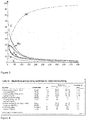
- Figure 2 shows a GDOES-measurement of the surface after depositing the molybdenum oxide on the nickel layer.
- the X-axis gives the thickness in nm and the Y-axis gives the concentration in wt%. Note that the values for carbon and sulphur are in fact 10 times as low as presented.
- the layer of molybdenum oxide on top of the nickel layer is 2 ⁇ m (i.e. 2000 nm), whereas the molybdenum oxide layer is about 60 nm.
- Figure 3 shows a GDOES-measurement of the surface after annealing the layers of Figure 2 .
- the values for carbon and sulphur are in fact 10 times as low as presented.
- the clearly discernable layer of molybdenum oxide on top of the nickel layer has vanished, and a diffusion layer comprising nickel and molybdenum is shown.
- There is still a degree of oxygen present in the surface layers but this is believed to be associated with re-oxidation if the surface, and with the presence of the phosphates, and not with the molybdenum oxide which has reduced to metallic molybdenum.
Landscapes
- Chemical & Material Sciences (AREA)
- Engineering & Computer Science (AREA)
- Organic Chemistry (AREA)
- Materials Engineering (AREA)
- Metallurgy (AREA)
- Chemical Kinetics & Catalysis (AREA)
- Electrochemistry (AREA)
- Mechanical Engineering (AREA)
- Thermal Sciences (AREA)
- Physics & Mathematics (AREA)
- Crystallography & Structural Chemistry (AREA)
- Combustion & Propulsion (AREA)
- General Engineering & Computer Science (AREA)
- Inorganic Chemistry (AREA)
- Health & Medical Sciences (AREA)
- Toxicology (AREA)
- Electroplating Methods And Accessories (AREA)
- Other Surface Treatments For Metallic Materials (AREA)
Description
- This invention relates to a method for producing a corrosion resistant metal substrate and corrosion resistant metal substrate provided thereby.
- Materials used for exhaust piping, mufflers, and other exhaust system components consist mainly of ferrous alloys. Aluminium alloys are sometimes used as a coating on ferrous alloys to impart additional corrosion resistance. The choice of exhaust system materials is driven by a number of factors including cost, warranty requirements and legislated and customer demands for long service life. Mild carbon steel was the material of choice for exhaust systems for many decades. An iron oxide coating on the exhaust system protected it from atmospheric corrosion to varying degrees. However, it suffered from poor corrosion resistance when exposed to road salt and exhaust condensate. As a result, exhaust systems made from this material had a very short life if exposed to the environment experienced by many on-road vehicles. The corrosion resistance of carbon steel can be greatly improved through the use of a hot dipped aluminium coating. This is often referred to as aluminised steel.
- One particularly important ferrous alloy alloying element is chromium. By adding sufficient chromium, stainless steel is formed. When stainless steel is heated, chromium forms a protective chromium oxide coating that delays further oxidation. A minimum of about 10.5% chromium is usually required to passivate the surface and to classify a material as stainless steel. So long as this oxide layer is stable and continuous, the metal substrate is well protected from corrosion. Since about the mid-1990s, plain carbon and low alloy steels have been replaced by stainless steel as the primary material for exhaust systems. This transition has taken place because of market demands for extended warranties, and because of demands mandated by emission standards. Technologies to meet increasingly stringent emission standards can raise exhaust temperatures which makes the task of meeting strength and durability requirements especially challenging. Emission standards also require that exhaust systems are designed in a manner that facilitates leak-free assembly, installation and operation for the full useful life of the vehicle.
- From the early part of the 21st century, commodities including many of the alloying elements used in stainless steel, have experienced wide and rapid price fluctuations. Emission control systems such as actively regenerated diesel particulate filters (DPFs) and urea selective catalytic reduction (SCR) have also created new demands on material properties. Active DPF regeneration can produce exhaust temperatures as high as 800°C in parts of the exhaust system that would otherwise operate at much lower temperatures. Also, some commonly used stainless steels, such as type 304, have been found to corrode after exposure to urea decomposition products in high temperature environments.
-
US2010/0167087 discloses a steel or aluminum substrate electroplated with a corrosion resistant alloy layer of Ni-Mo. - It is an object of the present invention to provide a new corrosion resistant substrate.
- It is also an object of the present invention to provide a new corrosion resistant substrate for applications at high temperatures.
- It is also an object of the present invention to provide a new corrosion resistant substrate for applications at high temperatures on the basis of a low cost ferrous substrate.
- It is also an object of the present invention to provide a low cost method for producing a corrosion resistant substrate, suitable for applications at high temperatures.
- One or more of the objects is reached by a method for producing a corrosion resistant metal substrate by electroplating:
- i. a nickel or nickel-based layer on a steel or aluminium substrate, or
- ii. a nickel or nickel-based layer on a steel or aluminium substrate followed by providing a cobalt layer on the nickel or nickel-based layer,
to form a plated substrate followed by electrodepositing a molybdenum oxide layer from an aqueous solution onto the plated substrate, wherein the plated substrate acts as a cathode, wherein the aqueous solution comprises a molybdenum salt and an alkali metal phosphate and wherein the pH of the aqueous solution is adjusted to between 4.0 and 6.5, wherein the plated substrate provided with the molybdenum oxide layer is subjected to an annealing step in a reducing atmosphere to, at least partly, reduce the molybdenum oxide in the molybdenum oxide layer to molybdenum metal in a reduction annealing step and to form, simultaneously or subsequently, in the annealing step a diffusion layer which contains nickel and molybdenum, and optionally cobalt, wherein the nickel originates from the nickel or nickel-based layer, the cobalt originates from the optional cobalt layer, and the molybdenum originates from the molybdenum oxide layer. - The diffusion layer contains nickel, molybdenum and optionally cobalt. There may be other components in the diffusion layer such as phosphate.
- The metal substrate, which may be provided in the form of a coiled strip of steel such as (low) carbon steel or stainless steel, or in the form a coiled strip of aluminium or aluminium alloy with a suitable chemical composition for the application of the final product, is provided with a nickel layer, or a nickel-based layer, and optionally with a cobalt layer on top of the nickel or nickel-based layer to form a plated substrate. Nickel layers can for instance be deposited onto the substrate in a Watts nickel plating bath. A nickel-based layer is a layer predominantly consisting of nickel but not solely of nickel. A nickel alloy layer is therefore considered a nickel based layer. Unless indicated otherwise, the term "nickel layer" hereinafter intends to include "nickel-based layer". The corrosion protection offered by the nickel layer may be insufficient for certain applications as a result of the presence of pores in the nickel layer. The cobalt layer is used to improve the corrosion resistance of the nickel plated substrate. The plated substrate is then led through the said aqueous solution in an electroplating device in which the plated substrate acts as the cathode, and provided with the molybdenum oxide layer. The molybdenum oxide in the molybdenum oxide layer is then reduced to molybdenum metal in a reduction annealing step and, as a consequence of the high temperature during the reduction annealing step, the molybdenum diffuses into the nickel and/or cobalt layer, thereby forming a diffusion layer comprising nickel, molybdenum and optionally cobalt. So the reduction annealing step is also the diffusion annealing step. This is the preferable case. However, if necessary, the annealing step can be prolonged to further promote the diffusion after the reduction of the molybdenum oxide has been completed. Preferably the reducing atmosphere is a hydrogen containing atmosphere, such as substantially pure hydrogen or HNX.
- The inventors found that the diffusion layer comprising nickel and molybdenum, and optionally cobalt, is pore free, and provides an excellent protection of the substrate. The pores in the nickel or nickel-alloy layer, if present, are closed as a result of the use of the method according to the invention.
- It should be noted that after the reduction annealing step in principle all molybdenum oxide is reduced to molybdenum metal. However, after exposure of the annealed strip to the ambient atmosphere the outermost surface may reoxidise. On a 150 nm thick diffusion layer a 20 to 30 nm thick oxide layer may be present.
- In an embodiment the molybdenum salt is ammonium molybdate ((NH4)6Mo7O24). The advantage of the use of ammonium as the cation is that it decomposes during the heat treatment. Other molybdenum salts would result in deposits on the surface. E.g. sodium-molybdate would result in the presence of sodium on the surface which would result in an undesirable alkaline corrosion reaction.
- In an embodiment the phosphate is sodium dihydrogen phosphate (NaH2PO4). This functions acts both a conducting salt in the electrolyte and as a buffer salt. The buffer ensures that the right pH-value of the electrolyte is maintained. Potassium dihydrogen phosphate (KH2PO4) could technically also be used, alone or as a mixture with NaH2PO4, but KH2PO4 is currently more expensive and therefore economically less attractive.
- In further embodiments of the invention wherein the nickel layer (or nickel-based layer) provided on the substrate is between 0.5 and 5 µm in thickness. This thickness range provides sufficient thickness for the diffusion layer after the reduction annealing to be effective. It is preferable that the diffusion layer comprising of nickel, originating from the nickel or nickel-based layer, and optionally cobalt, originating from the optional cobalt layer, and molybdenum, originating from the reduced molybdenum oxide layer, has a thickness of between 10 and 200 nm. A preferable minimum thickness is 20 nm, and a preferable maximum thickness is 150 nm. Preferably the thickness of the diffusion layer is between 50 and 100 nm.
- In an embodiment
- the temperature of the aqueous solution for the electrodeposition of the molybdenum oxide layer onto the nickel plated substrate is between 40 °C and 75 °C, and/or
- the plating time for the electrodeposition of the molybdenum oxide layer onto the nickel plated substrate is between 5 and 30 seconds, and/or
- the current density for the electrodeposition of the molybdenum oxide layer onto the nickel plated substrate is between 2 and 25 A/dm2, and/or
- the maximum annealing temperature during the annealing step is between 500 and 1050 °C, and/or
- the annealing time is between 6 and 10 hours for a batch annealing process or between 10 and 120 seconds for a continuous annealing process.
- These features are independent and can be applied separately or in combination.
- Preferably the temperature of the aqueous solution is at least 51 °C and/or at most 69 °C. The plating time is preferably at most 20 seconds, whereas it is preferable that the current density for the electrodeposition of the molybdenum oxide layer is at least 6 and/or at most 22 A/dm2. More preferably the temperature of the aqueous solution is at least 55 °C and/or at most 65 °C.
- In an embodiment
- the plating time for the electrodeposition of the cobalt layer onto the nickel plated substrate is between 5 and 40 seconds, and/or
- the current density for the electrodeposition of the cobalt layer onto the nickel plated substrate is between 2 and 25 A/dm2, and/or
- In relation to the maximum annealing temperature during the annealing step a distinction can be made in dependence of the substrate. It was found that for a low-carbon steel substrate the maximum annealing temperature is 700 °C, preferably 650 °C and more preferably 600 °C to prevent too large an impact on the properties of the steel substrate. For a stainless steel substrate the maximum annealing temperature is 900 °C, preferably 850 °C and more preferably 800 °C to prevent too large an impact on the properties of the steel substrate. Both for low-carbon (LC) steel substrates as for stainless steel substrates the lower limit of the annealing temperature is controlled largely by the lay-out of the annealing facilities and of the economy of the process. The lower the temperature, the longer it takes for a Ni-Mo-diffusion layer of a desired thickness to form.
- For an aluminium or aluminium alloy substrate, the allowable temperatures are lower. For such a substrate the maximum annealing temperature depends on the alloy is at most 500 and preferably at most 450 °C to prevent too large an impact on the properties of the substrate. A suitable temperature can be determined easily by simple trial and error. As the temperature is lower, the required diffusion time increases.
- The annealing time in the batch annealing process is between 6 and 10 hours, preferably at most 8.5 hours and more preferably at most 7.5 hours. For a continuous annealing process the annealing time is at most 120 seconds, preferably at most 95 s, more preferably at most 75 s and even more preferably at most 40 s. A suitable minimum continuous annealing temperature is 5 s, preferably at least 10 s. There is a degree of interchangeability between the annealing time and the annealing temperature. It should be noted that when referring to an annealing time of 8.5 hours in a batch annealing furnace this intends to mean that the cold spot of the (coiled) material reaches the set temperature in 8.5 hours, after which the cooling starts. A total cycle of heating and cooling may therefore be considerably longer than 8.5 hours and be more than double that value.
- In an embodiment the aqueous solution for the electrodeposition of the molybdenum oxide layer onto the plated substrate comprises:
- between 10 and 50 g/l of (NH4)6Mo7O24, and/or
- between 20 and 80 g/l of NaH2PO4.
- This composition allows to effectively and reproducibly deposit the molybdenum oxide layer. It is noted that 30 g/l of (NH4)6Mo7O24 corresponds to 0.024 mol/l and 50 g/l of NaH2PO4 to 0.42 mol/l.
- In a preferable embodiment the thickness of the deposited molybdenum oxide layer is at most 100 nm, preferably at most 75, more preferably 50 nm, and even more preferably 40 nm. Preferably the minimum thickness is at least 10 nm.
- In an embodiment the pH of the aqueous solution is at least 4.5 and/or at most 6. Preferably the pH is at least 5.25 and/or at most 5.75.
- In a preferable embodiment wherein the cathodic current density for depositing the molybdenum oxide layer is at least 12.5 A/dm2 and preferably at least 15 A/dm2.
- Preferably the steel substrate is a carbon steel, preferably a low carbon steel, extra-low carbon steel or a HSLA-steel. These unalloyed (LC and ELC) or micro-alloyed (HSLA) steels are relatively cheap substrates and provide good strength and formability. The steels are produced by means of commonly known processes such as casting, hot-rolling and cold-rolling. Low carbon steels typically comprise 0.05 to 0.15 wt.% C and extra low carbon steels typically comprise 0.02 to 0.05 wt.% C. Other elements may be present in addition to carbon in accordance with EN 10020-2000 which prescribes how much of a certain element may be present to still be considered an unalloyed steel. High-strength low-alloy (HSLA) steels (aka micro-alloyed steels) are designed to provide better mechanical properties and/or greater resistance to atmospheric corrosion than carbon steels. The HSLA steels have low carbon contents (0.05-0.15% C) in order to produce adequate formability and weldability, and they have manganese contents up to 2.0%. Small quantities of chromium, nickel, molybdenum, copper, nitrogen, vanadium, niobium, titanium and zirconium are used in various combinations to achieve the desired properties. It is preferable that the steel substrate has been cold-rolled to its final thickness, usually between 0.15 and 1.5 mm, and the cold-rolled steel substrate may or may not have been recrystallisation or recovery annealed prior to depositing the nickel and optional cobalt layer according to the invention. The steel substrate is preferably supplied in the form of a coiled strip.
- In an embodiment of the invention the steel substrate is a ferritic stainless steel, such as an SAE 400-series, which generally are considered to have better engineering properties than austenitic stainless steel grades, but have reduced corrosion resistance, because of the lower chromium and nickel content. They are also usually less expensive. Ferritic stainless steels have a body-centered cubic crystal structure and contain between 10.5% and 27% chromium with very little nickel, if any. By means of a non-limiting example the steel SAE 430 (1.4016) proved to be a useful substrate for the method according to the invention. It is preferable that the stainless steel substrate has been cold-rolled to its final thickness, usually between 0.15 and 1.5 mm, and the cold-rolled steel substrate may or may not have been recrystallisation or recovery annealed prior to depositing the nickel and optional cobalt layer according to the invention. The stainless steel substrate is preferably supplied in the form of a coiled strip.
- The substrate for the method according to the invention may also be an aluminium or an aluminium alloy substrate.
- In an embodiment the diffusion layer comprising of nickel originating from the nickel or nickel-based layer and molybdenum originating from the molybdenum oxide layer also comprises phosphor, preferably 5 to 15 wt.% of phosphor, more preferably 6 to 13 wt.%. A suitable maximum amount is 10 wt.%. A suitable minimum amount is 7 wt.%. Although the oxidation state of the phosphor is not exactly known, it is believed that the phosphor originated from the phosphate in the electrolyte. It may even still be present as phosphate in the layer. It is believed that its presence contributes to the corrosion protection of the layer.
- According to a second aspect, the invention is also embodied in a corrosion resistant metal substrate provided with a diffusion layer comprising nickel, molybdenum and optionally cobalt, produced according to the invention wherein the diffusion layer (i.e. the Ni-Mo- or Ni-Mo-Co-diffusion layer) has a thickness of between 10 and 200 nm. A preferable minimum thickness is 20 nm, and a preferable maximum thickness is 150 nm. Preferably the thickness of the Ni-Mo-diffusion layer is between 50 and 100 nm. This thickness can be determined e.g. by means of GDOES. The thickness of the layer is determined by locating the halfvalue (ignoring the surface effects) of the Mo-curve. The thickness in
Figure 2 (before annealing) results in a NiMo-layer thickness of 60 nm and inFigure 3 in a Mo-alloy layer of 80 nm. It is noted thatFigure 3 shows that the tail of the Mo-signal inFigure 3 is much more pronounced than inFigure 2 as a result of the diffusion of the Mo into the nickel layer. - According to a third aspect, the invention is embodied in the use of the above corrosion resistant substrate for the production of an exhaust system or parts for an exhaust system produced from the metal substrate according to the invention. In another embodiment of the invention the metal substrate according to the invention is used in fuel lines for instance for internal combustion engines.
- The invention will now be further explained by means of the following, non-limitative examples.
- An aqueous solution was prepared consisting of 30 g/l of (NH4)6Mo7O24 (0.024 mol/l) and 50 g/l of NaH2PO4 (0.42 mol/l) with a pH of 5.5 and maintained at 60 °C. A molybdenum-oxide layer was deposited on a 2 µm matt nickel plated low-carbon steel using a current density of 20 A/dm2 and a plating time of 15 and 10 seconds. This material was then annealed in a reducing hydrogen atmosphere for 7.3 hours in a batch annealing furnace. The resulting Ni-Mo-diffusion layer has a thickness of about 150 nm at the surface of the coated substrate. These materials were subsequently tested in a salt spray test (NSS) according to ISO 9227:2012 at 5% NaCl and 35 °C and the corrosion protection for the 10 seconds plating time layer was up to 21 hrs (Ni-layer, both sides 2 µm). Also the number of pores in the Ni-Mo-diffusion layer was much reduced. The pores were determined visually on a sample which was subjected to an aqueous solution as described in the ferroxyl test in ASTM A380. The rating of samples is a qualitative rating, but quite indicative for its performance under corrosive conditions, such as in exhaust applications.
- Experiments using the conditions above result in the following linear dependence of the amount of Mo deposited on plating time (measured after annealing using Atomic Absorption Spectroscopy after dissolution of the layer of the substrate in HCl (1:1)).
Plating time A/dm2 mg (Mo) / m2 5 20 94 10 20 128 15 20 174 20 20 220 -
Figure 1 shows a non-limitative example of the implementation of the process according to the invention. The hot-rolled starting product is pickled to remove the oxides from the strip and clean the surface. After pickling the strip is cold-rolled. In the plating step the various layers are electrodeposited. In the annealing step the diffusion annealing takes place. The cold-rolling can obviously also take place elsewhere when the cold-rolled coil is bought from a supplier of cold rolled coil. -
Figure 2 shows a GDOES-measurement of the surface after depositing the molybdenum oxide on the nickel layer. The X-axis gives the thickness in nm and the Y-axis gives the concentration in wt%. Note that the values for carbon and sulphur are infact 10 times as low as presented. Clearly visible is the layer of molybdenum oxide on top of the nickel layer. The nickel layer is 2 µm (i.e. 2000 nm), whereas the molybdenum oxide layer is about 60 nm. -
Figure 3 shows a GDOES-measurement of the surface after annealing the layers ofFigure 2 . Note that the values for carbon and sulphur are infact 10 times as low as presented. The clearly discernable layer of molybdenum oxide on top of the nickel layer has vanished, and a diffusion layer comprising nickel and molybdenum is shown. There is still a degree of oxygen present in the surface layers, but this is believed to be associated with re-oxidation if the surface, and with the presence of the phosphates, and not with the molybdenum oxide which has reduced to metallic molybdenum.
Claims (15)
- A method for producing a corrosion resistant metal substrate by providing:i. a nickel or nickel-based layer on a steel or aluminium substrate, orii. a nickel or nickel-based layer on a steel or aluminium substrate followed by providing a cobalt layer on the nickel or nickel-based layer,to form a plated substrate followed by electrodepositing a molybdenum oxide layer from an aqueous solution onto the plated substrate, wherein the plated substrate acts as a cathode, wherein the aqueous solution comprises a molybdenum salt and an alkali metal phosphate and wherein the pH of the aqueous solution is adjusted to between 4.0 and 6.5, wherein the plated substrate provided with the molybdenum oxide layer is subjected to an annealing step in a reducing atmosphere to, at least partly and preferably fully, reduce the molybdenum oxide in the molybdenum oxide layer to molybdenum metal in a reduction annealing step and to form, simultaneously or subsequently, in the annealing step a diffusion layer which contains nickel and molybdenum, and optionally cobalt, wherein the nickel originates from the nickel or nickel-based layer, the cobalt originates from the optional cobalt layer, and the molybdenum originates from the molybdenum oxide layer.
- The method according to claim 1, wherein the molybdenum salt is ammonium molybdate.
- The method according to claim 1 or 2, wherein the phosphate is sodium dihydrogen phosphate.
- The method according to any one of the preceding claims, wherein the nickel or nickel-based layer provided on the substrate is between 0.5 and 5 µm in thickness, and/or wherein the diffusion layer has a thickness of between 10 and 200 nm.
- The method according to any one of the preceding claims, wherein:- the temperature of the aqueous solution for the electrodeposition of the molybdenum oxide layer onto the nickel plated steel or aluminium substrate is between 40 °C and 75 °C, and/or- the plating time for the electrodeposition of the molybdenum oxide layer onto the nickel plated steel or aluminium substrate is between 5 and 30 seconds, and/or- the current density for the electrodeposition of the molybdenum oxide layer onto the nickel plated steel or aluminium substrate is between 2 and 25 A/dm2, and/or- the maximum annealing temperature during the annealing step is between 500 and 1050 °C, and/or- the annealing time is between 6 and 10 hours for a batch annealing process and between 10 and 120 seconds for a continuous annealing process.
- The method according to any one of the preceding claims, wherein the aqueous solution for the electrodeposition of the molybdenum oxide layer onto the nickel plated steel or aluminium substrate comprises:- between 10 and 50 g/l of (NH4)6Mo7O24, and/or- between 20 and 80 g/l of NaH2PO4.
- The method according to any one of the preceding claims, wherein the aqueous solution is maintained at a temperature between 50 and 70°C and/or wherein the pH of the aqueous solution is at least 4.5 and/or at most 6.
- The method according to any one of the preceding claims, the thickness of the deposited molybdenum oxide layer is at most 50 nm.
- The method according to any one of the preceding claims, wherein the cathodic current density is at least 12.5 A/dm2 and/or at most 22.5 A/dm2.
- The method according to any one of the preceding claims, wherein the reducing atmosphere is a hydrogen containing atmosphere.
- The method according to any one of the preceding claims, wherein the substrate is a steel substrate, preferably a carbon steel, more preferably a low carbon steel.
- The method according to any one of claims 1 to 10, wherein the substrate is a ferritic stainless steel substrate.
- The method according to any one of the preceding claims, wherein the diffusion layer comprising of nickel originating from the nickel or nickel-based layer and molybdenum originating from the molybdenum oxide layer also comprises 5 to 15 wt.% of elemental phosphate.
- A corrosion resistant metal substrate provided with a diffusion layer which contains nickel and molybdenum, and optionally cobalt, on a steel or aluminium substrate, produced according to the method of any one of claims 1 to 13 wherein the diffusion layer has a thickness of between 10 and 200 nm.
- Use of the corrosion resistant metal substrate according to claim 14 for the production of an exhaust system or parts for an exhaust system or a fuel line.
Applications Claiming Priority (2)
| Application Number | Priority Date | Filing Date | Title |
|---|---|---|---|
| EP2016150383 | 2016-01-07 | ||
| PCT/EP2017/050291 WO2017118751A1 (en) | 2016-01-07 | 2017-01-08 | Method for producing a corrosion resistant metal substrate and corrosion resistant metal substrate provided thereby |
Publications (2)
| Publication Number | Publication Date |
|---|---|
| EP3400324A1 EP3400324A1 (en) | 2018-11-14 |
| EP3400324B1 true EP3400324B1 (en) | 2019-10-09 |
Family
ID=63721217
Family Applications (1)
| Application Number | Title | Priority Date | Filing Date |
|---|---|---|---|
| EP17700205.2A Active EP3400324B1 (en) | 2016-01-07 | 2017-01-08 | Method for producing a corrosion resistant metal substrate and corrosion resistant metal substrate provided thereby |
Country Status (1)
| Country | Link |
|---|---|
| EP (1) | EP3400324B1 (en) |
Families Citing this family (1)
| Publication number | Priority date | Publication date | Assignee | Title |
|---|---|---|---|---|
| CN113130214B (en) * | 2021-03-17 | 2022-10-14 | 上海应用技术大学 | NF @ molybdenum oxide @ nickel cobalt-LDH composite material and preparation method and application thereof |
-
2017
- 2017-01-08 EP EP17700205.2A patent/EP3400324B1/en active Active
Non-Patent Citations (1)
| Title |
|---|
| None * |
Also Published As
| Publication number | Publication date |
|---|---|
| EP3400324A1 (en) | 2018-11-14 |
Similar Documents
| Publication | Publication Date | Title |
|---|---|---|
| JP4724780B2 (en) | Aluminum-plated steel sheet for rapid heating hot press, manufacturing method thereof, and rapid heating hot pressing method using the same | |
| US10337388B2 (en) | Corrosion resistant metal substrate | |
| JPS63290292A (en) | Production of thinly tinned steel sheet having superior rust resistance and weldability | |
| TR201904325T4 (en) | Method for the production of alloyed hot-dip galvanized steel plates and steel parts for use in hot stamping. | |
| JP7307307B2 (en) | Aluminum-plated steel sheets for butt welding, butt-welding parts, and hot press-formed products | |
| JPH04214895A (en) | Surface treated steel sheet excellent in plating performance and weldability and manufacture thereof | |
| KR102074773B1 (en) | Fe-X Flash Electronic Plating Solution, Method for Manufacturing the Galvanized Steel Sheet and Galvanized Steel Sheet Thereof | |
| WO2023155868A1 (en) | High-strength steel composite galvanized sheet resistant to lme cracking during spot welding, and preparation method therefor | |
| EP3400324A1 (en) | Method for producing a corrosion resistant metal substrate and corrosion resistant metal substrate provided thereby | |
| CN111989419B (en) | Hot-dip Sn-Zn alloy-plated steel sheet and method for producing same | |
| JP4860537B2 (en) | Automotive parts with excellent corrosion resistance at joints | |
| JPH0328359A (en) | Production of hot-dip aluminized chromium-containing steel sheet | |
| JP2001355051A (en) | Hot-dip Zn-Sn-based plated steel sheet with excellent corrosion resistance | |
| JPS5932556B2 (en) | Manufacturing method of chromate-coated steel sheet for containers with excellent weldability and corrosion resistance after painting | |
| JP2000204463A (en) | Rustproof steel plate for fuel tanks with excellent weldability, corrosion resistance and durability | |
| JPS63186860A (en) | Manufacture of surface-treated steel sheet excellent in rust resistance and weldability | |
| JP2004002931A (en) | Aluminum-plated steel sheet with excellent resistance weldability and processed parts using it | |
| TWI896367B (en) | Melt-coated steel | |
| JPH0520514B2 (en) | ||
| JPS5947040B2 (en) | Steel plate for containers with excellent weldability and corrosion resistance after painting and its manufacturing method | |
| JPS5932557B2 (en) | Manufacturing method of chromate-coated steel sheet for containers with excellent weldability and corrosion resistance after painting | |
| JPS6123786A (en) | Manufacture of steel sheet for vessel having superior corrosion resistance | |
| JPS642195B2 (en) | ||
| JP2724045B2 (en) | Method for producing chromium-containing steel sheet plated with hot-dip zinc or zinc alloy | |
| JPS5989791A (en) | Method for modifying surface characteristic of cold rolled steel sheet |
Legal Events
| Date | Code | Title | Description |
|---|---|---|---|
| STAA | Information on the status of an ep patent application or granted ep patent |
Free format text: STATUS: UNKNOWN |
|
| STAA | Information on the status of an ep patent application or granted ep patent |
Free format text: STATUS: THE INTERNATIONAL PUBLICATION HAS BEEN MADE |
|
| PUAI | Public reference made under article 153(3) epc to a published international application that has entered the european phase |
Free format text: ORIGINAL CODE: 0009012 |
|
| STAA | Information on the status of an ep patent application or granted ep patent |
Free format text: STATUS: REQUEST FOR EXAMINATION WAS MADE |
|
| 17P | Request for examination filed |
Effective date: 20180807 |
|
| AK | Designated contracting states |
Kind code of ref document: A1 Designated state(s): AL AT BE BG CH CY CZ DE DK EE ES FI FR GB GR HR HU IE IS IT LI LT LU LV MC MK MT NL NO PL PT RO RS SE SI SK SM TR |
|
| AX | Request for extension of the european patent |
Extension state: BA ME |
|
| GRAP | Despatch of communication of intention to grant a patent |
Free format text: ORIGINAL CODE: EPIDOSNIGR1 |
|
| STAA | Information on the status of an ep patent application or granted ep patent |
Free format text: STATUS: GRANT OF PATENT IS INTENDED |
|
| INTG | Intention to grant announced |
Effective date: 20190227 |
|
| DAV | Request for validation of the european patent (deleted) | ||
| DAX | Request for extension of the european patent (deleted) | ||
| GRAS | Grant fee paid |
Free format text: ORIGINAL CODE: EPIDOSNIGR3 |
|
| GRAJ | Information related to disapproval of communication of intention to grant by the applicant or resumption of examination proceedings by the epo deleted |
Free format text: ORIGINAL CODE: EPIDOSDIGR1 |
|
| GRAL | Information related to payment of fee for publishing/printing deleted |
Free format text: ORIGINAL CODE: EPIDOSDIGR3 |
|
| STAA | Information on the status of an ep patent application or granted ep patent |
Free format text: STATUS: REQUEST FOR EXAMINATION WAS MADE |
|
| INTC | Intention to grant announced (deleted) | ||
| GRAR | Information related to intention to grant a patent recorded |
Free format text: ORIGINAL CODE: EPIDOSNIGR71 |
|
| STAA | Information on the status of an ep patent application or granted ep patent |
Free format text: STATUS: GRANT OF PATENT IS INTENDED |
|
| GRAA | (expected) grant |
Free format text: ORIGINAL CODE: 0009210 |
|
| STAA | Information on the status of an ep patent application or granted ep patent |
Free format text: STATUS: THE PATENT HAS BEEN GRANTED |
|
| AK | Designated contracting states |
Kind code of ref document: B1 Designated state(s): AL AT BE BG CH CY CZ DE DK EE ES FI FR GB GR HR HU IE IS IT LI LT LU LV MC MK MT NL NO PL PT RO RS SE SI SK SM TR |
|
| INTG | Intention to grant announced |
Effective date: 20190903 |
|
| REG | Reference to a national code |
Ref country code: GB Ref legal event code: FG4D |
|
| REG | Reference to a national code |
Ref country code: CH Ref legal event code: EP |
|
| REG | Reference to a national code |
Ref country code: IE Ref legal event code: FG4D |
|
| REG | Reference to a national code |
Ref country code: DE Ref legal event code: R096 Ref document number: 602017007678 Country of ref document: DE |
|
| REG | Reference to a national code |
Ref country code: AT Ref legal event code: REF Ref document number: 1188918 Country of ref document: AT Kind code of ref document: T Effective date: 20191115 |
|
| REG | Reference to a national code |
Ref country code: NL Ref legal event code: FP |
|
| REG | Reference to a national code |
Ref country code: LT Ref legal event code: MG4D |
|
| REG | Reference to a national code |
Ref country code: AT Ref legal event code: MK05 Ref document number: 1188918 Country of ref document: AT Kind code of ref document: T Effective date: 20191009 |
|
| PG25 | Lapsed in a contracting state [announced via postgrant information from national office to epo] |
Ref country code: AT Free format text: LAPSE BECAUSE OF FAILURE TO SUBMIT A TRANSLATION OF THE DESCRIPTION OR TO PAY THE FEE WITHIN THE PRESCRIBED TIME-LIMIT Effective date: 20191009 Ref country code: PT Free format text: LAPSE BECAUSE OF FAILURE TO SUBMIT A TRANSLATION OF THE DESCRIPTION OR TO PAY THE FEE WITHIN THE PRESCRIBED TIME-LIMIT Effective date: 20200210 Ref country code: ES Free format text: LAPSE BECAUSE OF FAILURE TO SUBMIT A TRANSLATION OF THE DESCRIPTION OR TO PAY THE FEE WITHIN THE PRESCRIBED TIME-LIMIT Effective date: 20191009 Ref country code: PL Free format text: LAPSE BECAUSE OF FAILURE TO SUBMIT A TRANSLATION OF THE DESCRIPTION OR TO PAY THE FEE WITHIN THE PRESCRIBED TIME-LIMIT Effective date: 20191009 Ref country code: NO Free format text: LAPSE BECAUSE OF FAILURE TO SUBMIT A TRANSLATION OF THE DESCRIPTION OR TO PAY THE FEE WITHIN THE PRESCRIBED TIME-LIMIT Effective date: 20200109 Ref country code: SE Free format text: LAPSE BECAUSE OF FAILURE TO SUBMIT A TRANSLATION OF THE DESCRIPTION OR TO PAY THE FEE WITHIN THE PRESCRIBED TIME-LIMIT Effective date: 20191009 Ref country code: LV Free format text: LAPSE BECAUSE OF FAILURE TO SUBMIT A TRANSLATION OF THE DESCRIPTION OR TO PAY THE FEE WITHIN THE PRESCRIBED TIME-LIMIT Effective date: 20191009 Ref country code: BG Free format text: LAPSE BECAUSE OF FAILURE TO SUBMIT A TRANSLATION OF THE DESCRIPTION OR TO PAY THE FEE WITHIN THE PRESCRIBED TIME-LIMIT Effective date: 20200109 Ref country code: FI Free format text: LAPSE BECAUSE OF FAILURE TO SUBMIT A TRANSLATION OF THE DESCRIPTION OR TO PAY THE FEE WITHIN THE PRESCRIBED TIME-LIMIT Effective date: 20191009 Ref country code: GR Free format text: LAPSE BECAUSE OF FAILURE TO SUBMIT A TRANSLATION OF THE DESCRIPTION OR TO PAY THE FEE WITHIN THE PRESCRIBED TIME-LIMIT Effective date: 20200110 Ref country code: LT Free format text: LAPSE BECAUSE OF FAILURE TO SUBMIT A TRANSLATION OF THE DESCRIPTION OR TO PAY THE FEE WITHIN THE PRESCRIBED TIME-LIMIT Effective date: 20191009 |
|
| PG25 | Lapsed in a contracting state [announced via postgrant information from national office to epo] |
Ref country code: RS Free format text: LAPSE BECAUSE OF FAILURE TO SUBMIT A TRANSLATION OF THE DESCRIPTION OR TO PAY THE FEE WITHIN THE PRESCRIBED TIME-LIMIT Effective date: 20191009 Ref country code: HR Free format text: LAPSE BECAUSE OF FAILURE TO SUBMIT A TRANSLATION OF THE DESCRIPTION OR TO PAY THE FEE WITHIN THE PRESCRIBED TIME-LIMIT Effective date: 20191009 Ref country code: IS Free format text: LAPSE BECAUSE OF FAILURE TO SUBMIT A TRANSLATION OF THE DESCRIPTION OR TO PAY THE FEE WITHIN THE PRESCRIBED TIME-LIMIT Effective date: 20200224 |
|
| PG25 | Lapsed in a contracting state [announced via postgrant information from national office to epo] |
Ref country code: AL Free format text: LAPSE BECAUSE OF FAILURE TO SUBMIT A TRANSLATION OF THE DESCRIPTION OR TO PAY THE FEE WITHIN THE PRESCRIBED TIME-LIMIT Effective date: 20191009 |
|
| REG | Reference to a national code |
Ref country code: DE Ref legal event code: R097 Ref document number: 602017007678 Country of ref document: DE |
|
| PG2D | Information on lapse in contracting state deleted |
Ref country code: IS |
|
| PG25 | Lapsed in a contracting state [announced via postgrant information from national office to epo] |
Ref country code: RO Free format text: LAPSE BECAUSE OF FAILURE TO SUBMIT A TRANSLATION OF THE DESCRIPTION OR TO PAY THE FEE WITHIN THE PRESCRIBED TIME-LIMIT Effective date: 20191009 Ref country code: EE Free format text: LAPSE BECAUSE OF FAILURE TO SUBMIT A TRANSLATION OF THE DESCRIPTION OR TO PAY THE FEE WITHIN THE PRESCRIBED TIME-LIMIT Effective date: 20191009 Ref country code: DK Free format text: LAPSE BECAUSE OF FAILURE TO SUBMIT A TRANSLATION OF THE DESCRIPTION OR TO PAY THE FEE WITHIN THE PRESCRIBED TIME-LIMIT Effective date: 20191009 Ref country code: IS Free format text: LAPSE BECAUSE OF FAILURE TO SUBMIT A TRANSLATION OF THE DESCRIPTION OR TO PAY THE FEE WITHIN THE PRESCRIBED TIME-LIMIT Effective date: 20200209 |
|
| PLBE | No opposition filed within time limit |
Free format text: ORIGINAL CODE: 0009261 |
|
| STAA | Information on the status of an ep patent application or granted ep patent |
Free format text: STATUS: NO OPPOSITION FILED WITHIN TIME LIMIT |
|
| PG25 | Lapsed in a contracting state [announced via postgrant information from national office to epo] |
Ref country code: SK Free format text: LAPSE BECAUSE OF FAILURE TO SUBMIT A TRANSLATION OF THE DESCRIPTION OR TO PAY THE FEE WITHIN THE PRESCRIBED TIME-LIMIT Effective date: 20191009 Ref country code: SM Free format text: LAPSE BECAUSE OF FAILURE TO SUBMIT A TRANSLATION OF THE DESCRIPTION OR TO PAY THE FEE WITHIN THE PRESCRIBED TIME-LIMIT Effective date: 20191009 Ref country code: MC Free format text: LAPSE BECAUSE OF FAILURE TO SUBMIT A TRANSLATION OF THE DESCRIPTION OR TO PAY THE FEE WITHIN THE PRESCRIBED TIME-LIMIT Effective date: 20191009 |
|
| REG | Reference to a national code |
Ref country code: CH Ref legal event code: PL |
|
| 26N | No opposition filed |
Effective date: 20200710 |
|
| PG25 | Lapsed in a contracting state [announced via postgrant information from national office to epo] |
Ref country code: LU Free format text: LAPSE BECAUSE OF NON-PAYMENT OF DUE FEES Effective date: 20200108 |
|
| PG25 | Lapsed in a contracting state [announced via postgrant information from national office to epo] |
Ref country code: LI Free format text: LAPSE BECAUSE OF NON-PAYMENT OF DUE FEES Effective date: 20200131 Ref country code: CH Free format text: LAPSE BECAUSE OF NON-PAYMENT OF DUE FEES Effective date: 20200131 Ref country code: SI Free format text: LAPSE BECAUSE OF FAILURE TO SUBMIT A TRANSLATION OF THE DESCRIPTION OR TO PAY THE FEE WITHIN THE PRESCRIBED TIME-LIMIT Effective date: 20191009 |
|
| PG25 | Lapsed in a contracting state [announced via postgrant information from national office to epo] |
Ref country code: IE Free format text: LAPSE BECAUSE OF NON-PAYMENT OF DUE FEES Effective date: 20200108 |
|
| PG25 | Lapsed in a contracting state [announced via postgrant information from national office to epo] |
Ref country code: TR Free format text: LAPSE BECAUSE OF FAILURE TO SUBMIT A TRANSLATION OF THE DESCRIPTION OR TO PAY THE FEE WITHIN THE PRESCRIBED TIME-LIMIT Effective date: 20191009 Ref country code: MT Free format text: LAPSE BECAUSE OF FAILURE TO SUBMIT A TRANSLATION OF THE DESCRIPTION OR TO PAY THE FEE WITHIN THE PRESCRIBED TIME-LIMIT Effective date: 20191009 Ref country code: CY Free format text: LAPSE BECAUSE OF FAILURE TO SUBMIT A TRANSLATION OF THE DESCRIPTION OR TO PAY THE FEE WITHIN THE PRESCRIBED TIME-LIMIT Effective date: 20191009 |
|
| PG25 | Lapsed in a contracting state [announced via postgrant information from national office to epo] |
Ref country code: MK Free format text: LAPSE BECAUSE OF FAILURE TO SUBMIT A TRANSLATION OF THE DESCRIPTION OR TO PAY THE FEE WITHIN THE PRESCRIBED TIME-LIMIT Effective date: 20191009 |
|
| P01 | Opt-out of the competence of the unified patent court (upc) registered |
Effective date: 20230517 |
|
| PGFP | Annual fee paid to national office [announced via postgrant information from national office to epo] |
Ref country code: CZ Payment date: 20231220 Year of fee payment: 8 |
|
| PGFP | Annual fee paid to national office [announced via postgrant information from national office to epo] |
Ref country code: NL Payment date: 20240126 Year of fee payment: 8 |
|
| PGFP | Annual fee paid to national office [announced via postgrant information from national office to epo] |
Ref country code: DE Payment date: 20240129 Year of fee payment: 8 Ref country code: GB Payment date: 20240129 Year of fee payment: 8 |
|
| PGFP | Annual fee paid to national office [announced via postgrant information from national office to epo] |
Ref country code: IT Payment date: 20240122 Year of fee payment: 8 Ref country code: FR Payment date: 20240125 Year of fee payment: 8 Ref country code: BE Payment date: 20240129 Year of fee payment: 8 |
|
| PG25 | Lapsed in a contracting state [announced via postgrant information from national office to epo] |
Ref country code: CZ Free format text: LAPSE BECAUSE OF NON-PAYMENT OF DUE FEES Effective date: 20250108 |
|
| REG | Reference to a national code |
Ref country code: DE Ref legal event code: R119 Ref document number: 602017007678 Country of ref document: DE |
|
| REG | Reference to a national code |
Ref country code: NL Ref legal event code: MM Effective date: 20250201 |
|
| GBPC | Gb: european patent ceased through non-payment of renewal fee |
Effective date: 20250108 |
|
| PG25 | Lapsed in a contracting state [announced via postgrant information from national office to epo] |
Ref country code: DE Free format text: LAPSE BECAUSE OF NON-PAYMENT OF DUE FEES Effective date: 20250801 |
|
| PG25 | Lapsed in a contracting state [announced via postgrant information from national office to epo] |
Ref country code: NL Free format text: LAPSE BECAUSE OF NON-PAYMENT OF DUE FEES Effective date: 20250201 |
|
| PG25 | Lapsed in a contracting state [announced via postgrant information from national office to epo] |
Ref country code: BE Free format text: LAPSE BECAUSE OF NON-PAYMENT OF DUE FEES Effective date: 20250131 Ref country code: GB Free format text: LAPSE BECAUSE OF NON-PAYMENT OF DUE FEES Effective date: 20250108 |
|
| PG25 | Lapsed in a contracting state [announced via postgrant information from national office to epo] |
Ref country code: FR Free format text: LAPSE BECAUSE OF NON-PAYMENT OF DUE FEES Effective date: 20250131 |
|
| REG | Reference to a national code |
Ref country code: BE Ref legal event code: MM Effective date: 20250131 |
|
| PG25 | Lapsed in a contracting state [announced via postgrant information from national office to epo] |
Ref country code: IT Free format text: LAPSE BECAUSE OF NON-PAYMENT OF DUE FEES Effective date: 20250108 |