EP3399651B1 - Duplexfiltervorrichtung, rru-system und funkfrequenzsystem - Google Patents
Duplexfiltervorrichtung, rru-system und funkfrequenzsystem Download PDFInfo
- Publication number
- EP3399651B1 EP3399651B1 EP16880949.9A EP16880949A EP3399651B1 EP 3399651 B1 EP3399651 B1 EP 3399651B1 EP 16880949 A EP16880949 A EP 16880949A EP 3399651 B1 EP3399651 B1 EP 3399651B1
- Authority
- EP
- European Patent Office
- Prior art keywords
- rru
- filter
- frequency band
- ant
- transmitting
- Prior art date
- Legal status (The legal status is an assumption and is not a legal conclusion. Google has not performed a legal analysis and makes no representation as to the accuracy of the status listed.)
- Active
Links
Images




Classifications
-
- H—ELECTRICITY
- H04—ELECTRIC COMMUNICATION TECHNIQUE
- H04B—TRANSMISSION
- H04B1/00—Details of transmission systems, not covered by a single one of groups H04B3/00 - H04B13/00; Details of transmission systems not characterised by the medium used for transmission
- H04B1/38—Transceivers, i.e. devices in which transmitter and receiver form a structural unit and in which at least one part is used for functions of transmitting and receiving
- H04B1/40—Circuits
Definitions
- the present invention relates to the field of radio frequency (RF), and particularly to a duplex filtering device, a Radio Remote Unit (RRU) system, and an RF system.
- RF radio frequency
- a duplex filter radio frequency (RF) device includes a master transmitting-receiving duplexer composed of a transmitting filter and a receiving filter and a diversity receiving filter composed of a separately filter.
- each of the transmitting filter and the receiving filter in the duplexer is composed of metal coaxial cavities.
- each of the transmitting filter and the receiving filter in a commonly used duplex filter RF device is composed of multiple metal resonant cavities.
- FIG.1 is a schematic diagram of a duplex filter and a system networking architecture related to the duplex filter in the related technology.
- the system networking architecture includes two radio remote units (RRUs), four inter-frequency combiners, a 4-port antenna, and multiple radio frequency cables.
- the RRU is composed of four modules: an intermediate frequency module, a transceiver module, a power amplifier module and a filtering module.
- the digital intermediate frequency module is configured to perform modulation/demodulation, digital up/down conversion and analogue to digital (A/D) conversion for optical transmission.
- the transceiver module is configured to transform an intermediate frequency signal to a radio frequency signal.
- the radio frequency signal is transmitted through a port of the antenna via the power amplifier module and the filtering module.
- the RRU performs frequency conversion, filtering and radio frequency filtering on based band signals, and amplifies the filtered radio frequency signals by means of a linear power amplifier and transmits the amplified signals via the antenna.
- the uplink signals received from mobile terminals are processed by the RRU, including filtering, low noise amplification, radio small-signal amplification filtering, down conversion, analog to digital conversion and digital intermediate frequency processing etc.
- the system networking architecture is complex and has a large number of cables, the number of the engineering components are increased, the reliability is low while the cost is high, which is unfavorable for operators to expand and upgrade the network.
- EP 2911305A1 discloses a multiplexer which solves the problem of how multi-mode signals share a transmitting channel, a receiving channel and a transceiving antenna by the above technical scheme.
- WO 2013/097395 A1 discloses an active antenna device which comprises digital processing modules, transmission and reception radio-frequency modules and an antenna array in sequence.
- the embodiments of the present invention provide a duplex filtering device, a RRU system, and an RF system, so as to at least solve the problems in the related technology that the diplex filter and the system networking architecture related to the duplex filter are complex and the number of cables is excessive.
- each of one end of the transmitting-receiving combiner and one end of a first group of filters composed of at least one receiving filter and at least one transmitting filter is connected to the first common interface ANT; each of another end of the transmitting-receiving combiner and one end of a second group of filters composed of at least one receiving filter and at least one transmitting filter is connected to the second common interface ANT, where each of the first common interface ANT and the second common interface ANT is connected to a respective external interface unit; the receiving filter in each of the first group of filters and the second group of filters is connected to a radio remote unit, RRU, through a respective input port RX; and the transmitting filter in each of the first group of filters and the second group of filters is connected to the RRU through a respective output port TX.
- the problems in the related technology that the diplex filter and the system networking architecture related to the duplex filter are complex and the number of cables is excessive are solved.
- FIG. 2 is a structural block diagram of a duplex filtering device according to an embodiment of the present invention.
- the duplex filtering device 200 includes at least one filtering unit 210.
- the filtering unit includes: a receiving filter 211, a transmitting filter 212, a transmitting-receiving combiner 213, and a common interface ANT 214.
- the common interface ANT 214 includes a first common interface ANT 214-1 and a second common interface ANT 214-2.
- Each of one end of the transmitting-receiving combiner 213 and one end of a first group of filters composed of at least one receiving filter 211 and at least one transmitting filter 212 is connected to the first common interface ANT 214-1.
- Each of another end of the transmitting-receiving combiner 213 and one end of a second group of filters composed of at least one receiving filter 211 and at least one transmitting filter 212 is connected to the second common interface ANT 214-2.
- each of the first common interface ANT 214-1 and the second common interface ANT 214-2 is connected to a respective external interface unit.
- the receiving filter 211 in each of the first group of filters and the second group of filters is connected to a RRU through a respective input port RX.
- the transmitting filter 212 in each of the first group of filters and the second group of filters is connected to the RRU through a respective output port TX.
- the first group of filters may include a first receiving filter and a first transmitting filter
- the second group of filters may include a second receiving filter and a second transmitting filter
- an ANT common end of each of the first transmitting filter, the transmitting-receiving combiner, and the first receiving filter is connected to the first common interface ANT.
- the first receiving filter is connected to the RRU through an input port RX and the first transmitting filter is connected to the RRU through an output port TX.
- Each of another ANT common end of the transmitting-receiving combiner, an ANT common end of the second receiving filter and an ANT common end of the second transmitting filter is connected to the second common interface ANT.
- the second receiving filter is connected to the RRU through an input port RX and the second transmitting filter is connected to the RRU through an output port TX.
- a passing frequency band of each of the first receiving filter and the second receiving filter may be a first frequency band.
- a passing frequency band of each of the first transmitting filter and the second transmitting filter may be a second frequency band.
- the first frequency band and the second frequency band may be different from each other.
- the passing frequency band of the transmitting-receiving combiner may be a third frequency band, which may be different from the first frequency band and the second frequency band.
- each of the first frequency band and the second frequency band may be 1800 frequency band and the third frequency band may be 2100 frequency band; or each of the first frequency band and the second frequency band may be 2100 frequency band and the third frequency band may be 1800 frequency band.
- values of the frequency bands in the above embodiments are merely examples and do not mean to limit the present invention. In other application scenarios of the present invention, the values of the frequency bands may be determined according to actual conditions.
- FIG. 3 is a structural block diagram of a RRU system according to an alternative embodiment of the present invention.
- the RRU system 300 includes an RRU 310 and the duplex filtering device 200 as illustrated in FIG.2 .
- the duplex filtering device 200 is connected to the RRU 310 through input ports RXs and output ports TXs and to external interfaces through the common interfaces ANT 214.
- the duplex filtering device includes N filtering units, the duplex filtering device is connected to the RRU through the input ports RX of the receiving filters and the output ports TX of the transmitting filters in each of the filtering units and to external interfaces through the common interfaces ANT 214.
- FIG. 4 is a structural block diagram of an antenna radio frequency system according to an embodiment of the present invention.
- the antenna radio frequency system includes an antenna unit 400 and at least two RRU systems 300 as illustrated in FIG.3 , a common interfaces ANT 214 of each of the RRU systems 300 is connected to a respective port of the antenna unit by means of RF cable connection.
- Fig. 4 is an example in which only one filtering unit in the filtering device is illustrated.
- the RRU system when the RRU system includes a first RRU system and a second RRU system.
- the antenna unit has N ports and the number of the common interfaces ANTs 214 is 2N.
- a first antenna port in the N-port antenna unit is connected to a first common interface ANT in the first RRU system by means of RF cable connection.
- a second common interface ANT in the first RRU system is connected to a (2N-1) th common interface ANT in the second RRU system by means of RF cable connection.
- a (2N-1) th common interface ANT in the first RRU system is connected to a second common interface ANT in the second RRU system by means of RF cable connection.
- a (2N) th common interface ANT in the first RRU system is connected to a second antenna port in the N-port antenna unit by means of RF cable connection.
- a first common interface ANT in the second RRU system is connected to a (2N-1) th antenna port in the N-port antenna unit by means of RF cable connection.
- a (2N) th common interface ANT in the second RRU system is connected to a (2N) th antenna port in the N-port antenna unit by means of RF cable connection.
- N is a natural number greater than or equal to 2.
- the RRU system 300 may include an RRU 310 and the duplex filtering device 200 as illustrated in FIG.2 .
- the RRU when the duplex filtering device includes one filtering unit, the RRU is connected to the input port RX of the first receiving filter, the input port RX of the second receiving filter, the output port TX of the first transmitting filter and the output port TX of the second transmit filter in the duplex filtering device.
- the duplex filtering device includes multiple filtering units, the RRU is connected to the input port RX of the first receiving filter, the input port RX of the second receiving filter, the output port TX of the first transmitting filter and the output port TX of the second transmit filter in each of the duplex filtering devices.
- the duplex filtering device, the RRU and the antenna are used for networking, the number of antenna feeders and radio frequency cables used in the wireless network can be reduced, so that the engineering installation is simplified and the maintenance costs are reduced.
- a duplex filter and a networking architecture based on the duplex filter are provided.
- the duplex filter includes multiple receiving filters, multiple transmitting filters, multiple common antenna ANT ports, multiple output ports TXs and multiple input ports RXs and so on.
- the embodiment further provides multiple networking architectures based on the duplex filter.
- FIG. 5 is a structural block diagram of a duplex filter according to an alternative embodiment of the present invention.
- the duplex filter in the alternative embodiment may include multiple filtering units, where a connection relationship in a first unit is as follows.
- Each of one end of Filter 1, one end of Filter 2, one end of Filter 3 is connected to a common interface ANT 1.
- Each of another end TX1 of the Filter 1 and another end RX1 of the Filter 2 is connected to an RRU RF processing unit.
- Another end of the Filter 3 is connected to a common interface ANT 2.
- Filter 1, Filter 2, and Filter 3 are filters with different passing frequency bands.
- Filter 3, Filter 4, and Filter 5 are filters with different passing frequency bands.
- Filter 1 and Filter 4 correspond to the first transmitting filter and the second transmitting filter respectively in the foregoing embodiments.
- Filter 2 and Filter 5 correspond to the first receiving filter and the second receiving filter respectively in the foregoing embodiments.
- Filter 3 corresponds to the transmitting-receiving combiner in the foregoing embodiments.
- a connection relationship in a second unit in the duplex filter is as follows.
- Each of one end of Filter 6, one end of Filter 7, and one end of Filter 8 is connected to a common interface ANT 3.
- Each of another end TX3 of the Filter 6 and another end RX3 of the Filter 7 is connected to the RRU RF processing unit.
- Another end of the Filter 8 is connected to a common interface ANT 4.
- Filter 6, Filter 7, and Filter 8 are filters with different passing frequency bands.
- Filter 8 Each of another end of Filter 8, one end of Filter 9, and one end of Filter 10 is connected to the common interface ANT 4.
- the one end of Filter 8 is connected to the common interface ANT 3.
- Each of another end of the Filter 9 (TX4) and another end of Filter 10 (RX4) is connected to the RRU RF processing unit.
- Filter 3, Filter 4, and Filter 5 are filters with different passing frequency bands;
- Filter 6 and Filter 9 correspond to the first transmitting filter and the second transmitting filter respectively in the foregoing embodiments
- Filter 7 and Filter 10 correspond to the first receiving filter and the second receiving filter respectively in the foregoing embodiments
- Filter 8 corresponds to the transmitting-receiving combiner in the foregoing embodiments.
- n th unit a connection relationship in the n th unit may be as follows.
- Each of one end of Filter 5n-4, one end of Filter 5n-3 and one end of Filter 5n-2 is connected to the common interface ANT 2n-1.
- Each of another end of the Filter 5n-4 (TX 2n-1) and another end of the Filter 5n-3 (RX 2n-1) is connected to the RRU RF processing unit.
- Another end of the Filter 5n-2 is connected to the common interface ANT 2n.
- Filter 5n-4, Filter 5n-3 and Filter 5n-2 are filters with different passing frequency bands.
- Each of another end of Filter 5n-2, one end of Filter 5n-1, and one end of Filter 5n is connected to the common interface ANT 2n.
- Each of another end of the Filter 5n-1 (TX 2n) and another end of Filter 5n (RX 2n) is connected to the RRU RF processing unit.
- Filter 5n-2, Filter 5n-1, and Filter 5n are filters with different passing frequency bands.
- FIG. 6 is a schematic diagram of a system networking architecture of the duplex filter according to an alternative embodiment of the present invention.
- the connection relationship in a networking architecture of a 2-port antenna unit is as follows.
- Port 1 of the 2-port antenna unit is connected to a common interface ANT 1 of the duplex filter by means of RF cable connection.
- Port 2 of the 2-port antenna unit is connected to ANT 4 of the duplex filter by means of RF cable connection.
- a common interface ANT 2 of the duplex filter is connected to ANT 2 in a second RRU by means of RF cable connection.
- a common interface ANT 3 of the duplex filter is connected to the common interface ANT 1 in the second RRU by means of RF cable connection. Therefore, a combined cabinet network composed of a 2-port antenna feeder is formed.
- FIG. 7 is a block diagram of a system network architecture of a 4-port antenna unit according to an alternative embodiment of the present invention.
- the connection relationship in a networking architecture of a 4-port antenna unit is as follows.
- An antenna port 1 of the 4-port antenna unit is connected to a common interface ANT 1 of the duplex filter in a first RRU system by means of RF cable connection.
- a common interface ANT 2 of the duplex filter in the first RRU system is connected to a common interface ANT 3 of the duplex filter in a second RRU system by means of RF cable connection.
- the common interface ANT 3 of the duplex filter in the first RRU system is connected to the common interface ANT 2 of the duplex filter in the second RRU system by means of RF cable connection.
- a common interface ANT 4 of the duplex filter in the first RRU system is connected to an antenna port 2 by means of RF cable connection.
- the common interface ANT 1 of the duplex filter in the second RRU system is connected to an antenna port 3 by means of RF cable connection.
- the common interface ANT 4 of the duplex filter in the second RRU system is connected to an antenna port 4 by means of RF cable connection.
- FIG. 8 is a block diagram of a system network architecture of a 2-port antenna unit according to an alternative embodiment of the present invention. As illustrated in FIG.8 , a first common interface ANT 1 in a first RRU system is connected to a first port of the 2-port antenna unit, a second common interface ANT 2 in the first RRU system is connected to a first common interface ANT 1 of a second RRU system, and a second common interface ANT 2 of the second RRU system is connected to a second port of the 2-port antenna unit.
- FIG. 9 is a block diagram of a system network architecture of an n-port antenna unit according to an alternative embodiment of the present invention.
- a connection relationship in a networking architecture of a n-port antenna unit is as follows.
- a first antenna port (port 1) in the n-port antenna unit is connected to a first common interface ANT 1 of the duplex filter in a first RRU system by means of RF cable connection.
- a second common interface ANT 2 of the duplex filter in the first RRU system is connected to a (2n-1) th common interface ANT 2n-1 of the duplex filter in the second RRU system by means of RF cable connection.
- a (2n-1) th common interface ANT 2n-1 of the duplex filter in the first RRU system is connected to a second common interface ANT 2 of the duplex filter in the second RRU system by means of RF cable connection.
- a (2n) th common interface ANT 2n in the first RRU system is connected to a second antenna port in the N-port antenna unit by means of RF cable connection.
- a first common interface ANT 1 in the second RRU system is connected to a (n-1) th antenna port in the N-port antenna unit by means of RF cable connection.
- a (2n) th common interface ANT 2n in the second RRU system is connected to an n th antenna port in the N-port antenna unit by means of RF cable connection. Therefore, a combined cabinet network composed of the n-port antenna is formed.
- a process of receiving signals by the duplex filter in the alternative embodiment may be as follows. Spatial wireless signals received at the first antenna port of the n-port antenna unit are transmitted to the first common interface ANT 1 of the duplex filter in the first RRU system by means of RF cable connection. One of the signals received at the first common interface ANT 1 is filtered by Filter 2 (a receiving filter) and transmitted to the first RRU RF processing unit through input port RX1.
- Filter 2 a receiving filter
- Another signal of the signals received at the first common interface ANT 1 is filtered by Filter 3 (a transmitting-receiving combiner) and transmitted to the (2n-1) th common interface ANT 2n-1 in the second RRU system by means of RF cable connection and filtered by Filter 5n-3 and finally transmitted to the second RRU RF processing unit through the input port RX 2n-1.
- Filter 3 a transmitting-receiving combiner
- Wireless signals received at the second antenna port are transmitted to the (2n) th common interface ANT 2n of the duplex filter in the first RRU system.
- One of the signals received at the (2n) th common interface ANT 2n of the duplex filter in the first RRU system is filtered by Filter 5n-2 and transmitted to the first RRU RF processing unit through input port RX 2n.
- Another signal of the signals received at the (2n) th common interface ANT 2n of the duplex filter in the first RRU system is filtered by Filter 5n-2 and transmitted to the second common interface ANT 2 in the second RRU system by means of RF cable connection and filtered by Filter 5 and finally transmitted to the second RRU RF processing unit through the input port RX 2.
- Signals received at output port TX1 from the first RRU RF processing unit are filtered by Filter 1 and transmitted to the first antenna port in the antenna unit by means of RF cable connection.
- signals received at output port TX2 from the first RRU RF processing unit are filtered by Filter 4 and transmitted to the (2n-1) th common interface ANT 2n-1 in the second RRU system by means of RF cable connection and combined by Filter 5n-2 to the (2n) th common interface ANT 2n in the second RRU system and finally transmitted to the antenna unit by means of RF cable connection.
- the n th signal received at output port TX 2n-1 from the first RRU RF processing unit are filtered by Filter 5n-4 and transmitted to the second common interface ANT 2 in the second RRU system by means of RF cable connection and combined by Filter 3 in the second RRU system to the first common interface ANT 1 in the second RRU system and finally transmitted to the antenna unit by means of RF cable connection.
- duplex filters having different passing frequency bands are provided.
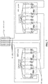
- FIG. 10 is a block diagram of a specific embodiment of a duplex filter according to an alternative embodiment of the present invention.
- the 1800 duplex filter includes: four 1800 transmitting filters (TX) (having a passing frequency band of 1800 frequency band, four 1800 receiving filters (RX) (having a passing frequency band of 1800 frequency band), two 2100 wideband combiners (having a passing frequency band of 2100 frequency band) (TRX) and four antenna ports (ANT1-ANT4).
- TX transmitting filters
- RX receiving filters
- TRX 2100 wideband combiners
- ANT1-ANT4 antenna ports
- the connection relationship in the duplex filter having the passing frequency band of 1800 frequency band is as follows.
- the antenna port ANT 1 is connected to each of one end of a transmitting filter (TX1) having the passing frequency band of 1800 frequency band.
- Each of another end of TX1 and another end of RX1 is connected to the RRU RF processing unit.
- Another end of the wideband combiner (TRX) having the passing frequency band of 2100 frequency band is connected to ANT 2.
- the transmitting filter (TX1) having the passing frequency band of 1800 frequency band, the receiving filter (RX1) having the passing frequency band of 1800 frequency band and the wideband combiner (TRX) having the passing frequency band of 2100 frequency band are three filters having different passing frequency bands.
- the antenna port ANT 2 is connected to each of one end of a transmitting filter (TX2) having the passing frequency band of 1800 frequency band, one end of a receiving filter (RX2) having the passing frequency band of 1800 frequency band.
- One end of the wideband combiner (TRX) having the passing frequency band of 2100 frequency band; the one end of the wideband combiner (TRX) having the passing frequency band of 2100 frequency band is connected to ANT 1.
- Each of another end of TX2 and another end of RX2 is connected to the RRU RF processing unit.
- the transmitting filter (TX2) having the passing frequency band of 1800 frequency band, the receiving filter (RX2) having the passing frequency band of 1800 frequency band and the wideband combiner (TRX) having the passing frequency band of 2100 frequency band are three filters having different passing frequency bands.
- the ANT 3, ANT 4 the transmitting filter having the passing frequency band of 1800 frequency band, the receiving filter having the passing frequency band of 1800 frequency band and the wideband combiner (TRX) having the passing frequency band of 2100 frequency band are interconnected in a same manner as the ANT 1 and ANT 2, and therefore they will not be repeatedly described.
- the internal structure of the duplex filter having a passing frequency band of 2100 frequency band is as same as that of the duplex filter having a passing frequency band of 1800 frequency band, the difference between the two lies that the working frequency of the duplex filter having the passing frequency band of 2100 frequency band is different from that of the duplex filter having a passing frequency band of 1800 frequency band.
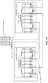
- FIG. 11 is a structural block diagram of a 2*4T4R networking architecture implemented by duplex filters according to an alternative embodiment of the present invention. As illustrated in FIG. 11 , the connection relationship in the 2*4T4R networking architecture is as follows. A first antenna port (port 1) of the 4-port antenna unit is connected to a common interface ANT 1 in an RRU system composed of the duplex filter having the passing frequency band of 1800 frequency band by means of radio frequency (RF) connection.
- RF radio frequency
- a common interface ANT 2 in the RRU system composed of the duplex filter having the passing frequency band of 1800 frequency band is connected to a common interface ANT 3 in an RRU system composed of the duplex filter having the passing frequency band of 2100 frequency band by means of RF connection.
- the common interface ANT 3 in the RRU system composed of the duplex filter having the passing frequency band of 1800 frequency band is connected to the common interface ANT 2 in the RRU system composed of the duplex filter having the passing frequency band of 2100 frequency band by means of RF connection.
- a common interface ANT 4 in the RRU system composed of the duplex filter having the passing frequency band of 1800 frequency band is connected to a second antenna port (port 2) of the 4-port antenna unit by means of RF connection.
- the common interface ANT 1 in the RRU system composed of the duplex filter having the passing frequency band of 2100 frequency band is connected to a third antenna port (port 3) of the 4-port antenna unit by means of RF connection.
- the common interface ANT 4 in the RRU system composed of the duplex filter having the passing frequency band of 2100 frequency band is connected to a fourth antenna port (port 4) of the 4-port antenna unit by means of RF connection, and therefore a 2*4T4R combined cabinet network composed of the 4-port antenna is formed.
- a process of receiving signals through the duplex filters in the 2*4T4R networking architecture in this alternative embodiment is as follows.
- Spatial wireless signals received at the first antenna port (port 1) of the 4-port antenna unit are transmitted to the first common interface ANT 1 in the RRU system composed of the duplex filter having the passing frequency band of 1800 frequency band by means of RF cable connection.
- One of the signals is filtered by the receiving filter (RX1) having the passing frequency band of 1800 frequency band and transmitted to an RRU RF processing unit in 1800 frequency band.
- Another signal of the signals received by the first common interface ANT 1 in the RRU system composed of the duplex filter having the passing frequency band of 1800 frequency band is filtered by the RRU combiner (TRX) in the 1800 frequency band and transmitted to the common interface ANT 3 in the RRU system composed by the duplex filter having the passing frequency band of 2100 frequency band by means of RF cable connection, filtered by the receiving filter (RX3) in the 2100 frequency band RRU system, and finally transmitted to the RRU RF processing unit in 2100 frequency band.
- TRX RRU combiner
- wireless signals received at the second antenna port (port 2) are transmitted to the fourth common interface ANT 4 in the RRU system in 1800 frequency band.
- One of the signals is filtered by the receiving filter (RX4) in 1800 frequency band and transmitted to the RRU RF processing unit in 1800 frequency band.
- Another signal of the signals is filtered by the combiner (2100 frequency band/ TRX) in the RRU system in 1800 frequency band and transmitted to the ANT 2 in the RRU system in 2100 frequency band by means of RF connection, filtered by Filter 5 and transmitted to the RRU RF processing unit in 2100 frequency band through the input port RX2.
- Signals transmitted by the RRU RF processing unit in the 1800 frequency band are filtered by the transmitting filter (TX1) in the 1800 frequency band and transmitted through the common interface ANT 1 to the antenna unit by means of RF cable connection.
- Signals received at the output port TX2 from the RRU RF processing unit in the 1800 frequency band are filtered by the transmitting filter (Filter 4/TX2) in the 1800 frequency band and transmitted to the common interface ANT 3 in the RRU system in the 2100 frequency band by means of RF cable connection, and combined by the combiner (1800 frequency band/TRX) in the RRU system in the 2100 frequency band to the common interface ANT 4 in the RRU system in the 2100 frequency band and finally transmitted to the fourth antenna port of the antenna unit by means of RF cable connection.
- Signals received at the output port TX3 from the RRU RF processing unit in the 1800 frequency band are filtered by the transmitting filter (Filter 6/TX3) in the 1800 frequency band and transmitted to the common interface ANT 2 in the RRU system in the 2100 frequency band by means of RF cable connection, and combined by the combiner (1800 frequency band/TRX) in the RRU system in the 2100 frequency band to the common interface ANT 1 in the RRU system in the 2100 frequency band and finally transmitted to the antenna unit by means of RF cable connection.
- the transmitting filter Finter 6/TX3
- the combiner (1800 frequency band/TRX) in the RRU system in the 2100 frequency band to the common interface ANT 1 in the RRU system in the 2100 frequency band and finally transmitted to the antenna unit by means of RF cable connection.
- Signals received at the output port TX4 from the RRU RF processing unit in the 1800 frequency band are filtered by the transmitting filter (Filter 9/TX4) in the 1800 frequency band and transmitted to the second antenna port of the antenna unit by means of RF cable connection.
- the transmitting filter Finter 9/TX4
- a duplex filtering device, an RRU system and an RF system provided by the embodiments of the present invention have the following beneficial effects.
- Each of one end of the transmitting-receiving combiner and one end of a first group of filters composed of at least one receiving filter and at least one transmitting filter is connected to the first common interface ANT.
- Each of another end of the transmitting-receiving combiner and one end of a second group of filters composed of at least one receiving filter and at least one transmitting filter is connected to the second common interface ANT.
- Each of the first common interface ANT and the second common interface ANT is connected to a respective external interface unit.
- the receiving filter in each of the first group of filters and the second group of filters is connected to a radio remote unit, RRU, through a respective input port RX.
- the transmitting filter in each of the first group of filters and the second group of filters is connected to the RRU through a respective output port TX.
Landscapes
- Engineering & Computer Science (AREA)
- Computer Networks & Wireless Communication (AREA)
- Signal Processing (AREA)
- Transceivers (AREA)
Claims (12)
- Duplex-Filtereinrichtung (200), umfassend zumindest eine Filtereinheit, dadurch gekennzeichnet, dass die Filtereinheit umfasst: Empfangsfilter (211), Sendefilter (212), einen Sender-Empfänger-Kombinator (213) und gemeinsame Schnittstellen (ANT 214), wobei die gemeinsamen Schnittstellen (ANT 214) eine erste gemeinsame Schnittstelle (ANT 214-1) und eine zweite gemeinsame Schnittstelle (ANT 214-2) umfasst, wobei der Sender-Empfänger-Kombinator (213) ein Filter ist, und wobeiein Ende des Sender-Empfänger-Kombinators (213) und ein Ende einer ersten Filtergruppe, die aus zumindest einem der Empfangsfilter (211) und zumindest einem der Sendefilter (212) gebildet ist, jeweils mit der ersten gemeinsamen Schnittstelle (ANT 214-1) verbunden sind;ein anderes Ende des Sender-Empfänger-Kombinators (213) und ein Ende einer zweiten Filtergruppe, die aus zumindest einem der Empfangsfilter (211) und zumindest einem der Sendefilter (212) gebildet ist, jeweils mit der zweiten gemeinsamen Schnittstelle (ANT 214-2) verbunden sind, wobei die erste gemeinsame Schnittstelle (ANT 214-1) und die zweite gemeinsame Schnittstelle (ANT 214-2) jeweils mit einer jeweiligen externen Schnittstelleneinheit verbunden sind;der Empfangsfilter (211) aus der ersten Filtergruppe durch einen ersten Eingangsport (RX) mit einer Funkferneinheit, RRU, verbunden ist und der Empfangsfilter (211) aus der zweiten Filtergruppe durch einen zweiten Eingangsport (RX) mit der RRU verbunden ist; undder Sendefilter (212) aus der ersten Filtergruppe durch einen ersten Ausgangsport (TX) mit der RRU verbunden ist und der Sendefilter (212) aus der zweiten Filtergruppe durch einen zweiten Ausgangsport (TX) mit der RRU verbunden ist.
- Duplex-Filtereinrichtung nach Anspruch 1, wobei die erste Filtergruppe einen ersten Empfangsfilter (211) und einen ersten Sendefilter (212) umfasst und die zweite Filtergruppe einen zweiten Empfangsfilter (211) und einen zweiten Sendefilter (212) umfasst, wobeiein gemeinsames ANT-Ende des ersten Sendefilters (212), ein gemeinsames ANT-Ende des Sender-Empfänger-Kombinators (213), und ein gemeinsames ANT-Ende des ersten Empfangsfilters (211) mit der ersten gemeinsamen Schnittstelle (ANT 214-1) verbunden sind;der erste Empfangsfilter (211) durch den ersten Eingangsport (RX) mit der RRU verbunden ist und der erste Sendefilter (212) durch den ersten Ausgangsport (TX) mit der RRU verbunden ist;ein anderes gemeinsames ANT-Ende des Sender-Empfänger-Kombinators (213), ein gemeinsames ANT-Ende des zweiten Empfangsfilters (211), und ein gemeinsames ANT-Ende des zweiten Sendefilters (212) mit der zweiten gemeinsamen Schnittstelle (ANT 214-2) verbunden sind; undder zweite Empfangsfilter (211) durch den zweiten Eingangsport (RX) mit der RRU verbunden ist und der zweite Sendefilter (212) durch den zweiten Ausgangsport (TX) mit der RRU verbunden ist.
- Duplex-Filtereinrichtung nach Anspruch 2, wobeies sich bei einem Durchlassfrequenzband des ersten Empfangsfilters (211) bzw. des zweiten Empfangsfilters (211) um ein erstes Frequenzband und beim Durchlassfrequenzband des ersten Sendefilters (212) bzw. des zweiten Sendefilters (212) um ein zweites Frequenzband handelt, wobei das erste Frequenzband und das zweite Frequenzband voneinander unterschiedlich sind; undes sich bei einem Durchlassfrequenzband des Sender-Empfänger-Kombinators (213) um ein drittes Frequenzband handelt, wobei das dritte Frequenzband von dem ersten Frequenzband und dem zweiten Frequenzband unterschiedlich ist.
- Duplex-Filtereinrichtung nach einem der Ansprüche 1 bis 3, wobei die Duplex-Filtereinrichtung N Filtereinheiten umfasst,
wobei jeder der Empfangsfilter (211) in jeder der Filtereinheiten durch einen jeweiligen Eingangsport (RX) mit der RRU verbunden ist, und jeder der Sendefilter (212) in jeder der Filtereinheiten durch einen jeweiligen Ausgangsport (TX) mit der RRU verbunden ist, wobei N eine Ganzzahl größer als 1 ist. - System (300) mit Funkferneinheit, RRU, umfassend:
eine RRU (310), dadurch gekennzeichnet, dass es weiterhin umfasst:die Duplex-Filtereinrichtung (200) nach einem der Ansprüche 1 bis 4;wobei die Duplex-Filtereinrichtung (200) durch die Eingangsports (RX) und die Ausgangsports (TX) mit der RRU (310) verbunden ist. - System (300) mit RRU nach Anspruch 5, wobei im Fall, in dem die Duplex-Filtereinrichtung (200) N Filtereinheiten umfasst, die Duplex-Filtereinrichtung (200) durch die Eingangsports (RX) der Empfangsfilter und die Ausgangsports (TX) der Sendefilter in jeder der Filtereinheiten mit der RRU (310) verbunden ist.
- Radiofrequenzsystem, RF-System, umfassend eine Antenneneinheit (400), dadurch gekennzeichnet, dass es weiterhin zumindest zwei Systeme (300) mit Funkferneinheit, RRU, nach Anspruch 5 oder 6 umfasst,
wobei eine oder mehrere der gemeinsamen Schnittstellen (ANT) jedes der Systeme mit RRU mittels RF-Kabelverbindung mit einem oder mehreren Ports der Antenneneinheit verbunden ist oder sind. - RF-System nach Anspruch 7, im Fall, in dem das System (300) mit RRU ein erstes System mit RRU und ein zweites System mit RRU umfasst und die Antenneneinheit (400) ein Antenneneinheit mit 2 Ports ist und die Anzahl der gemeinsamen Schnittstellen (ANT) 4 beträgt,ein erster Antennenport (1) in der Antenneneinheit (400) mit 4 Ports mittels RF-Kabelverbindung mit einer ersten gemeinsamen Schnittstelle (ANT 1) in dem ersten System mit RRU verbunden ist;eine zweite gemeinsame Schnittstelle (ANT 2) in dem ersten System mit RRU mittels RF-Kabelverbindung mit einer ersten gemeinsamen Schnittstelle (ANT 1) in dem zweiten System mit RRU verbunden ist; undeine zweite gemeinsame Schnittstelle (ANT 2) in dem zweiten System mit RRU mittels RF-Kabelverbindung mit einer zweiten gemeinsamen Schnittstelle (2) in der Antenneneinheit mit N Ports verbunden ist.
- RF-System nach Anspruch 7, im Fall, in dem die Systeme (300) mit RRU ein erstes System mit RRU und ein zweites System mit RRU umfassen und die Antenneneinheit (400) N Ports aufweist und die Anzahl der gemeinsamen Schnittstellen (ANT) 2N beträgt,ein erster Antennenport (1) in der Antenneneinheit (400) mit N Ports mittels RF-Kabelverbindung mit einer ersten gemeinsamen Schnittstelle (ANT 1) in dem ersten System mit RRU verbunden ist;eine zweite gemeinsame Schnittstelle (ANT 2) in dem ersten System mit RRU mittels RF-Kabelverbindung mit einer (2N-1)ten gemeinsamen Schnittstelle (ANT 2n-1) in dem zweiten System mit RRU verbunden ist;eine (2N-1)te gemeinsame Schnittstelle (ANT 2n-1) in dem ersten System mit RRU mittels RF-Kabelverbindung mit einer zweiten gemeinsamen Schnittstelle (ANT 2) in dem zweiten System mit RRU verbunden ist;eine (2N)te gemeinsame Schnittstelle (ANT 2n) in dem ersten System mit RRU mittels RF-Kabelverbindung mit einem (2) der Antennenports in der Antenneneinheit mit N Ports verbunden ist, eine erste gemeinsame Schnittstelle (ANT 1) in dem zweiten System mit RRU mittels RF-Kabelverbindung mit einem anderen (N-1) der Antennenports in der Antenneneinheit mit N Ports verbunden ist, und eine (2N)te gemeinsame Schnittstelle (ANT 2n) in dem zweiten System mit RRU mittels RF-Kabelverbindung mit einem weiteren (N) der Antennenports in der Antenneneinheit mit N Ports verbunden ist;wobei N eine natürliche Zahl größer als oder gleich 2 ist.
- RF-System nach Anspruch 8 oder 9, wobei jedes der Systeme mit RRU umfasst:eine RRU (310); unddie Duplex-Filtereinrichtung (200) nach einem der Ansprüche 1 bis 4;wobei die Duplex-Filtereinrichtung (200) eine Filtereinheit umfasst, die RRU (310) mit dem Eingangsport (RX) des ersten Empfangsfilters (211), dem Eingangsport (RX) des zweiten Empfangsfilters (211), dem Ausgangsport (TX) des ersten Sendefilters (212), und dem Ausgangsport (TX) des zweiten Sendefilters (212) in der Duplex-Filtereinrichtung (200) verbunden ist.
- RF-System nach Anspruch 8 oder 9, wobei jedes der Systeme mit RRU umfasst:eine RRU (310); unddie Duplex-Filtereinrichtung (200) nach einem der Ansprüche 1 bis 4;wobei die Duplex-Filtereinrichtung (200) mehrere Filtereinheiten umfasst, die RRU (310) mit dem Eingangsport (RX) des ersten Empfangsfilters (211), dem Eingangsport (RX) des zweiten Empfangsfilters (211), dem Ausgangsport (TX) des ersten Sendefilters (212), und dem Ausgangsport (TX) des zweiten Sendefilters (212) in jeder der Duplex-Filtereinrichtungen (200) verbunden ist.
- RF-System nach Anspruch 11, wobeies sich bei einem Durchlassfrequenzband des ersten Empfangsfilters (211) bzw. des zweiten Empfangsfilters (211) um ein erstes Frequenzband und beim Durchlassfrequenzband des ersten Sendefilters (212) bzw. des zweiten Sendefilters (212) um ein zweites Frequenzband handelt, wobei das erste Frequenzband und das zweite Frequenzband voneinander unterschiedlich sind; undes sich bei einem Durchlassfrequenzband des Sender-Empfänger-Kombinators (213) um ein drittes Frequenzband handelt, wobei das dritte Frequenzband von dem ersten Frequenzband und dem zweiten Frequenzband unterschiedlich ist.
Applications Claiming Priority (2)
| Application Number | Priority Date | Filing Date | Title |
|---|---|---|---|
| CN201511026973.3A CN106936463B (zh) | 2015-12-30 | 2015-12-30 | 双工滤波装置、rru系统及无线射频系统 |
| PCT/CN2016/109945 WO2017114159A1 (zh) | 2015-12-30 | 2016-12-14 | 双工滤波装置、rru系统及无线射频系统 |
Publications (3)
| Publication Number | Publication Date |
|---|---|
| EP3399651A1 EP3399651A1 (de) | 2018-11-07 |
| EP3399651A4 EP3399651A4 (de) | 2018-11-07 |
| EP3399651B1 true EP3399651B1 (de) | 2021-10-06 |
Family
ID=59224510
Family Applications (1)
| Application Number | Title | Priority Date | Filing Date |
|---|---|---|---|
| EP16880949.9A Active EP3399651B1 (de) | 2015-12-30 | 2016-12-14 | Duplexfiltervorrichtung, rru-system und funkfrequenzsystem |
Country Status (4)
| Country | Link |
|---|---|
| EP (1) | EP3399651B1 (de) |
| CN (1) | CN106936463B (de) |
| DK (1) | DK3399651T3 (de) |
| WO (1) | WO2017114159A1 (de) |
Families Citing this family (1)
| Publication number | Priority date | Publication date | Assignee | Title |
|---|---|---|---|---|
| CN117676778A (zh) * | 2022-08-30 | 2024-03-08 | 华为技术有限公司 | 一种通信方法及装置 |
Family Cites Families (7)
| Publication number | Priority date | Publication date | Assignee | Title |
|---|---|---|---|---|
| CN101771447B (zh) * | 2008-12-31 | 2014-03-19 | 中兴通讯股份有限公司 | 多载频信号发射、接收装置及发射接收系统 |
| CN101777932A (zh) * | 2009-12-23 | 2010-07-14 | 华为技术有限公司 | 天线振子复用的方法、装置和天线组件 |
| CN102570064B (zh) * | 2011-12-31 | 2016-08-24 | 南京中兴软件有限责任公司 | 有源天线装置及其收发信号的方法 |
| CN202565268U (zh) * | 2012-04-26 | 2012-11-28 | 何平 | 具有中间频段的td-lte室分mimo变频系统 |
| CN103840851A (zh) * | 2012-11-21 | 2014-06-04 | 中兴通讯股份有限公司 | 一种多工器 |
| CN103747447B (zh) * | 2013-12-03 | 2017-01-25 | 国家电网公司 | 一种数传电台与电力td‑lte专网共天线的系统及其实现方法 |
| CN203607549U (zh) * | 2013-12-06 | 2014-05-21 | 华为技术有限公司 | 一种有源天线系统 |
-
2015
- 2015-12-30 CN CN201511026973.3A patent/CN106936463B/zh active Active
-
2016
- 2016-12-14 EP EP16880949.9A patent/EP3399651B1/de active Active
- 2016-12-14 WO PCT/CN2016/109945 patent/WO2017114159A1/zh not_active Ceased
- 2016-12-14 DK DK16880949.9T patent/DK3399651T3/da active
Also Published As
| Publication number | Publication date |
|---|---|
| EP3399651A1 (de) | 2018-11-07 |
| WO2017114159A1 (zh) | 2017-07-06 |
| CN106936463A (zh) | 2017-07-07 |
| DK3399651T3 (da) | 2021-11-01 |
| CN106936463B (zh) | 2020-04-24 |
| EP3399651A4 (de) | 2018-11-07 |
Similar Documents
| Publication | Publication Date | Title |
|---|---|---|
| EP2911305B1 (de) | Multiplexer | |
| CN111327344A (zh) | 射频系统及电子设备 | |
| CN110380754B (zh) | 一种双频时分信号收发放大器 | |
| KR102779211B1 (ko) | 무선주파수 회로 및 전자기기 | |
| US8743744B2 (en) | Method and apparatus for multiplexing an antenna element, and antenna component | |
| US20200067542A1 (en) | Radio frequency front end module and radio frequency signal processing method | |
| US20140038531A1 (en) | High-frequency front-end circuit | |
| EP3065317B1 (de) | Co-frequenzbereichskombinator/-teiler und multisystemkombinierende plattform | |
| CN213367788U (zh) | 射频前端电路及电子设备 | |
| CN110445497A (zh) | 一种天线模组及终端 | |
| CN108933609B (zh) | Tdd/fdd可配置装置、方法、射频模块及通信设备 | |
| CN110504984A (zh) | 一种电子设备 | |
| EP3131214B1 (de) | Kombinator, basisstation, signalkombinatorsystem und verfahren zur signalübertragung | |
| CN103401599B (zh) | 一种针对多频段输入且带mimo功能的新型poi系统 | |
| CN103378900B (zh) | 施体天线装置、服务天线装置及其信号传输方法 | |
| EP3399651A1 (de) | Duplexfiltervorrichtung, rru-system und funkfrequenzsystem | |
| CN107070492A (zh) | 一种信号收发控制结构、方法及电子设备 | |
| CN203387500U (zh) | 针对多频段输入且带mimo功能的新型poi系统 | |
| CN104639201B (zh) | 一种基站的射频前端以及基站 | |
| CN107800460B (zh) | 用于跨频段载波聚合的射频拉远单元rru及传输方法 | |
| US20140334361A1 (en) | Apparatus for communication using simplex antennas | |
| EP2122744B1 (de) | Vorrichtung und verfahren zum lenken eines empfangssignals in einem antennensystem | |
| CN216414597U (zh) | 微型远端射频模块和室内分布系统 | |
| CN103401593A (zh) | 垂直极化接入装置及其分集接收系统 | |
| CN103762997B (zh) | 抗干扰电路及射频处理电路 |
Legal Events
| Date | Code | Title | Description |
|---|---|---|---|
| STAA | Information on the status of an ep patent application or granted ep patent |
Free format text: STATUS: THE INTERNATIONAL PUBLICATION HAS BEEN MADE |
|
| PUAI | Public reference made under article 153(3) epc to a published international application that has entered the european phase |
Free format text: ORIGINAL CODE: 0009012 |
|
| STAA | Information on the status of an ep patent application or granted ep patent |
Free format text: STATUS: REQUEST FOR EXAMINATION WAS MADE |
|
| 17P | Request for examination filed |
Effective date: 20180730 |
|
| A4 | Supplementary search report drawn up and despatched |
Effective date: 20181004 |
|
| AK | Designated contracting states |
Kind code of ref document: A1 Designated state(s): AL AT BE BG CH CY CZ DE DK EE ES FI FR GB GR HR HU IE IS IT LI LT LU LV MC MK MT NL NO PL PT RO RS SE SI SK SM TR |
|
| AX | Request for extension of the european patent |
Extension state: BA ME |
|
| DAV | Request for validation of the european patent (deleted) | ||
| DAX | Request for extension of the european patent (deleted) | ||
| GRAP | Despatch of communication of intention to grant a patent |
Free format text: ORIGINAL CODE: EPIDOSNIGR1 |
|
| STAA | Information on the status of an ep patent application or granted ep patent |
Free format text: STATUS: GRANT OF PATENT IS INTENDED |
|
| INTG | Intention to grant announced |
Effective date: 20210428 |
|
| GRAS | Grant fee paid |
Free format text: ORIGINAL CODE: EPIDOSNIGR3 |
|
| GRAA | (expected) grant |
Free format text: ORIGINAL CODE: 0009210 |
|
| STAA | Information on the status of an ep patent application or granted ep patent |
Free format text: STATUS: THE PATENT HAS BEEN GRANTED |
|
| AK | Designated contracting states |
Kind code of ref document: B1 Designated state(s): AL AT BE BG CH CY CZ DE DK EE ES FI FR GB GR HR HU IE IS IT LI LT LU LV MC MK MT NL NO PL PT RO RS SE SI SK SM TR |
|
| REG | Reference to a national code |
Ref country code: GB Ref legal event code: FG4D |
|
| REG | Reference to a national code |
Ref country code: CH Ref legal event code: EP Ref country code: AT Ref legal event code: REF Ref document number: 1437084 Country of ref document: AT Kind code of ref document: T Effective date: 20211015 |
|
| REG | Reference to a national code |
Ref country code: DE Ref legal event code: R096 Ref document number: 602016064752 Country of ref document: DE |
|
| REG | Reference to a national code |
Ref country code: IE Ref legal event code: FG4D |
|
| REG | Reference to a national code |
Ref country code: DK Ref legal event code: T3 Effective date: 20211027 |
|
| REG | Reference to a national code |
Ref country code: LT Ref legal event code: MG9D |
|
| REG | Reference to a national code |
Ref country code: NL Ref legal event code: MP Effective date: 20211006 |
|
| REG | Reference to a national code |
Ref country code: AT Ref legal event code: MK05 Ref document number: 1437084 Country of ref document: AT Kind code of ref document: T Effective date: 20211006 |
|
| PG25 | Lapsed in a contracting state [announced via postgrant information from national office to epo] |
Ref country code: RS Free format text: LAPSE BECAUSE OF FAILURE TO SUBMIT A TRANSLATION OF THE DESCRIPTION OR TO PAY THE FEE WITHIN THE PRESCRIBED TIME-LIMIT Effective date: 20211006 Ref country code: LT Free format text: LAPSE BECAUSE OF FAILURE TO SUBMIT A TRANSLATION OF THE DESCRIPTION OR TO PAY THE FEE WITHIN THE PRESCRIBED TIME-LIMIT Effective date: 20211006 Ref country code: FI Free format text: LAPSE BECAUSE OF FAILURE TO SUBMIT A TRANSLATION OF THE DESCRIPTION OR TO PAY THE FEE WITHIN THE PRESCRIBED TIME-LIMIT Effective date: 20211006 Ref country code: BG Free format text: LAPSE BECAUSE OF FAILURE TO SUBMIT A TRANSLATION OF THE DESCRIPTION OR TO PAY THE FEE WITHIN THE PRESCRIBED TIME-LIMIT Effective date: 20220106 Ref country code: AT Free format text: LAPSE BECAUSE OF FAILURE TO SUBMIT A TRANSLATION OF THE DESCRIPTION OR TO PAY THE FEE WITHIN THE PRESCRIBED TIME-LIMIT Effective date: 20211006 |
|
| PG25 | Lapsed in a contracting state [announced via postgrant information from national office to epo] |
Ref country code: IS Free format text: LAPSE BECAUSE OF FAILURE TO SUBMIT A TRANSLATION OF THE DESCRIPTION OR TO PAY THE FEE WITHIN THE PRESCRIBED TIME-LIMIT Effective date: 20220206 Ref country code: SE Free format text: LAPSE BECAUSE OF FAILURE TO SUBMIT A TRANSLATION OF THE DESCRIPTION OR TO PAY THE FEE WITHIN THE PRESCRIBED TIME-LIMIT Effective date: 20211006 Ref country code: PT Free format text: LAPSE BECAUSE OF FAILURE TO SUBMIT A TRANSLATION OF THE DESCRIPTION OR TO PAY THE FEE WITHIN THE PRESCRIBED TIME-LIMIT Effective date: 20220207 Ref country code: PL Free format text: LAPSE BECAUSE OF FAILURE TO SUBMIT A TRANSLATION OF THE DESCRIPTION OR TO PAY THE FEE WITHIN THE PRESCRIBED TIME-LIMIT Effective date: 20211006 Ref country code: NO Free format text: LAPSE BECAUSE OF FAILURE TO SUBMIT A TRANSLATION OF THE DESCRIPTION OR TO PAY THE FEE WITHIN THE PRESCRIBED TIME-LIMIT Effective date: 20220106 Ref country code: NL Free format text: LAPSE BECAUSE OF FAILURE TO SUBMIT A TRANSLATION OF THE DESCRIPTION OR TO PAY THE FEE WITHIN THE PRESCRIBED TIME-LIMIT Effective date: 20211006 Ref country code: LV Free format text: LAPSE BECAUSE OF FAILURE TO SUBMIT A TRANSLATION OF THE DESCRIPTION OR TO PAY THE FEE WITHIN THE PRESCRIBED TIME-LIMIT Effective date: 20211006 Ref country code: HR Free format text: LAPSE BECAUSE OF FAILURE TO SUBMIT A TRANSLATION OF THE DESCRIPTION OR TO PAY THE FEE WITHIN THE PRESCRIBED TIME-LIMIT Effective date: 20211006 Ref country code: GR Free format text: LAPSE BECAUSE OF FAILURE TO SUBMIT A TRANSLATION OF THE DESCRIPTION OR TO PAY THE FEE WITHIN THE PRESCRIBED TIME-LIMIT Effective date: 20220107 Ref country code: ES Free format text: LAPSE BECAUSE OF FAILURE TO SUBMIT A TRANSLATION OF THE DESCRIPTION OR TO PAY THE FEE WITHIN THE PRESCRIBED TIME-LIMIT Effective date: 20211006 |
|
| REG | Reference to a national code |
Ref country code: DE Ref legal event code: R097 Ref document number: 602016064752 Country of ref document: DE |
|
| PG25 | Lapsed in a contracting state [announced via postgrant information from national office to epo] |
Ref country code: SM Free format text: LAPSE BECAUSE OF FAILURE TO SUBMIT A TRANSLATION OF THE DESCRIPTION OR TO PAY THE FEE WITHIN THE PRESCRIBED TIME-LIMIT Effective date: 20211006 Ref country code: SK Free format text: LAPSE BECAUSE OF FAILURE TO SUBMIT A TRANSLATION OF THE DESCRIPTION OR TO PAY THE FEE WITHIN THE PRESCRIBED TIME-LIMIT Effective date: 20211006 Ref country code: RO Free format text: LAPSE BECAUSE OF FAILURE TO SUBMIT A TRANSLATION OF THE DESCRIPTION OR TO PAY THE FEE WITHIN THE PRESCRIBED TIME-LIMIT Effective date: 20211006 Ref country code: EE Free format text: LAPSE BECAUSE OF FAILURE TO SUBMIT A TRANSLATION OF THE DESCRIPTION OR TO PAY THE FEE WITHIN THE PRESCRIBED TIME-LIMIT Effective date: 20211006 Ref country code: CZ Free format text: LAPSE BECAUSE OF FAILURE TO SUBMIT A TRANSLATION OF THE DESCRIPTION OR TO PAY THE FEE WITHIN THE PRESCRIBED TIME-LIMIT Effective date: 20211006 |
|
| REG | Reference to a national code |
Ref country code: CH Ref legal event code: PL |
|
| PLBE | No opposition filed within time limit |
Free format text: ORIGINAL CODE: 0009261 |
|
| STAA | Information on the status of an ep patent application or granted ep patent |
Free format text: STATUS: NO OPPOSITION FILED WITHIN TIME LIMIT |
|
| 26N | No opposition filed |
Effective date: 20220707 |
|
| REG | Reference to a national code |
Ref country code: BE Ref legal event code: MM Effective date: 20211231 |
|
| PG25 | Lapsed in a contracting state [announced via postgrant information from national office to epo] |
Ref country code: LU Free format text: LAPSE BECAUSE OF NON-PAYMENT OF DUE FEES Effective date: 20211214 Ref country code: AL Free format text: LAPSE BECAUSE OF FAILURE TO SUBMIT A TRANSLATION OF THE DESCRIPTION OR TO PAY THE FEE WITHIN THE PRESCRIBED TIME-LIMIT Effective date: 20211006 |
|
| PG25 | Lapsed in a contracting state [announced via postgrant information from national office to epo] |
Ref country code: SI Free format text: LAPSE BECAUSE OF FAILURE TO SUBMIT A TRANSLATION OF THE DESCRIPTION OR TO PAY THE FEE WITHIN THE PRESCRIBED TIME-LIMIT Effective date: 20211006 Ref country code: BE Free format text: LAPSE BECAUSE OF NON-PAYMENT OF DUE FEES Effective date: 20211231 |
|
| PG25 | Lapsed in a contracting state [announced via postgrant information from national office to epo] |
Ref country code: LI Free format text: LAPSE BECAUSE OF NON-PAYMENT OF DUE FEES Effective date: 20211231 Ref country code: CH Free format text: LAPSE BECAUSE OF NON-PAYMENT OF DUE FEES Effective date: 20211231 |
|
| PG25 | Lapsed in a contracting state [announced via postgrant information from national office to epo] |
Ref country code: IT Free format text: LAPSE BECAUSE OF FAILURE TO SUBMIT A TRANSLATION OF THE DESCRIPTION OR TO PAY THE FEE WITHIN THE PRESCRIBED TIME-LIMIT Effective date: 20211006 |
|
| PG25 | Lapsed in a contracting state [announced via postgrant information from national office to epo] |
Ref country code: CY Free format text: LAPSE BECAUSE OF FAILURE TO SUBMIT A TRANSLATION OF THE DESCRIPTION OR TO PAY THE FEE WITHIN THE PRESCRIBED TIME-LIMIT Effective date: 20211006 |
|
| PG25 | Lapsed in a contracting state [announced via postgrant information from national office to epo] |
Ref country code: HU Free format text: LAPSE BECAUSE OF FAILURE TO SUBMIT A TRANSLATION OF THE DESCRIPTION OR TO PAY THE FEE WITHIN THE PRESCRIBED TIME-LIMIT; INVALID AB INITIO Effective date: 20161214 |
|
| PG25 | Lapsed in a contracting state [announced via postgrant information from national office to epo] |
Ref country code: MK Free format text: LAPSE BECAUSE OF FAILURE TO SUBMIT A TRANSLATION OF THE DESCRIPTION OR TO PAY THE FEE WITHIN THE PRESCRIBED TIME-LIMIT Effective date: 20211006 |
|
| PG25 | Lapsed in a contracting state [announced via postgrant information from national office to epo] |
Ref country code: MT Free format text: LAPSE BECAUSE OF FAILURE TO SUBMIT A TRANSLATION OF THE DESCRIPTION OR TO PAY THE FEE WITHIN THE PRESCRIBED TIME-LIMIT Effective date: 20211006 |
|
| PG25 | Lapsed in a contracting state [announced via postgrant information from national office to epo] |
Ref country code: TR Free format text: LAPSE BECAUSE OF FAILURE TO SUBMIT A TRANSLATION OF THE DESCRIPTION OR TO PAY THE FEE WITHIN THE PRESCRIBED TIME-LIMIT Effective date: 20211006 |
|
| PGFP | Annual fee paid to national office [announced via postgrant information from national office to epo] |
Ref country code: DE Payment date: 20250930 Year of fee payment: 10 |
|
| PGFP | Annual fee paid to national office [announced via postgrant information from national office to epo] |
Ref country code: GB Payment date: 20251001 Year of fee payment: 10 |
|
| PGFP | Annual fee paid to national office [announced via postgrant information from national office to epo] |
Ref country code: MC Payment date: 20251127 Year of fee payment: 10 |
|
| PGFP | Annual fee paid to national office [announced via postgrant information from national office to epo] |
Ref country code: DK Payment date: 20251212 Year of fee payment: 10 |
|
| PGFP | Annual fee paid to national office [announced via postgrant information from national office to epo] |
Ref country code: FR Payment date: 20251008 Year of fee payment: 10 |
|
| PGFP | Annual fee paid to national office [announced via postgrant information from national office to epo] |
Ref country code: IE Payment date: 20251001 Year of fee payment: 10 |