EP3399622A1 - Charging/discharging control device - Google Patents
Charging/discharging control device Download PDFInfo
- Publication number
- EP3399622A1 EP3399622A1 EP17741002.4A EP17741002A EP3399622A1 EP 3399622 A1 EP3399622 A1 EP 3399622A1 EP 17741002 A EP17741002 A EP 17741002A EP 3399622 A1 EP3399622 A1 EP 3399622A1
- Authority
- EP
- European Patent Office
- Prior art keywords
- electric drive
- drive circuit
- phase
- charging
- igbt module
- Prior art date
- Legal status (The legal status is an assumption and is not a legal conclusion. Google has not performed a legal analysis and makes no representation as to the accuracy of the status listed.)
- Granted
Links
Images




Classifications
-
- H—ELECTRICITY
- H02—GENERATION; CONVERSION OR DISTRIBUTION OF ELECTRIC POWER
- H02J—ELECTRIC POWER NETWORKS; CIRCUIT ARRANGEMENTS OR SYSTEMS FOR SUPPLYING OR DISTRIBUTING ELECTRIC POWER; SYSTEMS FOR STORING ELECTRIC ENERGY
- H02J7/00—Circuit arrangements for charging or discharging batteries or for supplying loads from batteries
- H02J7/02—Circuit arrangements for charging or discharging batteries or for supplying loads from batteries for charging batteries from AC mains by converters
-
- H—ELECTRICITY
- H02—GENERATION; CONVERSION OR DISTRIBUTION OF ELECTRIC POWER
- H02J—ELECTRIC POWER NETWORKS; CIRCUIT ARRANGEMENTS OR SYSTEMS FOR SUPPLYING OR DISTRIBUTING ELECTRIC POWER; SYSTEMS FOR STORING ELECTRIC ENERGY
- H02J7/00—Circuit arrangements for charging or discharging batteries or for supplying loads from batteries
- H02J7/02—Circuit arrangements for charging or discharging batteries or for supplying loads from batteries for charging batteries from AC mains by converters
- H02J7/04—Regulation of charging current or voltage
- H02J7/06—Regulation of charging current or voltage using discharge tubes or semiconductor devices
-
- B—PERFORMING OPERATIONS; TRANSPORTING
- B60—VEHICLES IN GENERAL
- B60L—PROPULSION OF ELECTRICALLY-PROPELLED VEHICLES; SUPPLYING ELECTRIC POWER FOR AUXILIARY EQUIPMENT OF ELECTRICALLY-PROPELLED VEHICLES; ELECTRODYNAMIC BRAKE SYSTEMS FOR VEHICLES IN GENERAL; MAGNETIC SUSPENSION OR LEVITATION FOR VEHICLES; MONITORING OPERATING VARIABLES OF ELECTRICALLY-PROPELLED VEHICLES; ELECTRIC SAFETY DEVICES FOR ELECTRICALLY-PROPELLED VEHICLES
- B60L50/00—Electric propulsion with power supplied within the vehicle
- B60L50/50—Electric propulsion with power supplied within the vehicle using propulsion power supplied by batteries or fuel cells
- B60L50/51—Electric propulsion with power supplied within the vehicle using propulsion power supplied by batteries or fuel cells characterised by AC-motors
-
- B—PERFORMING OPERATIONS; TRANSPORTING
- B60—VEHICLES IN GENERAL
- B60L—PROPULSION OF ELECTRICALLY-PROPELLED VEHICLES; SUPPLYING ELECTRIC POWER FOR AUXILIARY EQUIPMENT OF ELECTRICALLY-PROPELLED VEHICLES; ELECTRODYNAMIC BRAKE SYSTEMS FOR VEHICLES IN GENERAL; MAGNETIC SUSPENSION OR LEVITATION FOR VEHICLES; MONITORING OPERATING VARIABLES OF ELECTRICALLY-PROPELLED VEHICLES; ELECTRIC SAFETY DEVICES FOR ELECTRICALLY-PROPELLED VEHICLES
- B60L53/00—Methods of charging batteries, specially adapted for electric vehicles; Charging stations or on-board charging equipment therefor; Exchange of energy storage elements in electric vehicles
- B60L53/20—Methods of charging batteries, specially adapted for electric vehicles; Charging stations or on-board charging equipment therefor; Exchange of energy storage elements in electric vehicles characterised by converters located in the vehicle
- B60L53/22—Constructional details or arrangements of charging converters specially adapted for charging electric vehicles
-
- B—PERFORMING OPERATIONS; TRANSPORTING
- B60—VEHICLES IN GENERAL
- B60L—PROPULSION OF ELECTRICALLY-PROPELLED VEHICLES; SUPPLYING ELECTRIC POWER FOR AUXILIARY EQUIPMENT OF ELECTRICALLY-PROPELLED VEHICLES; ELECTRODYNAMIC BRAKE SYSTEMS FOR VEHICLES IN GENERAL; MAGNETIC SUSPENSION OR LEVITATION FOR VEHICLES; MONITORING OPERATING VARIABLES OF ELECTRICALLY-PROPELLED VEHICLES; ELECTRIC SAFETY DEVICES FOR ELECTRICALLY-PROPELLED VEHICLES
- B60L53/00—Methods of charging batteries, specially adapted for electric vehicles; Charging stations or on-board charging equipment therefor; Exchange of energy storage elements in electric vehicles
- B60L53/20—Methods of charging batteries, specially adapted for electric vehicles; Charging stations or on-board charging equipment therefor; Exchange of energy storage elements in electric vehicles characterised by converters located in the vehicle
- B60L53/24—Using the vehicle's propulsion converter for charging
-
- B—PERFORMING OPERATIONS; TRANSPORTING
- B62—LAND VEHICLES FOR TRAVELLING OTHERWISE THAN ON RAILS
- B62D—MOTOR VEHICLES; TRAILERS
- B62D5/00—Power-assisted or power-driven steering
- B62D5/04—Power-assisted or power-driven steering electrical, e.g. using an electric servo-motor connected to, or forming part of, the steering gear
- B62D5/0457—Power-assisted or power-driven steering electrical, e.g. using an electric servo-motor connected to, or forming part of, the steering gear characterised by control features of the drive means as such
- B62D5/046—Controlling the motor
-
- H—ELECTRICITY
- H02—GENERATION; CONVERSION OR DISTRIBUTION OF ELECTRIC POWER
- H02J—ELECTRIC POWER NETWORKS; CIRCUIT ARRANGEMENTS OR SYSTEMS FOR SUPPLYING OR DISTRIBUTING ELECTRIC POWER; SYSTEMS FOR STORING ELECTRIC ENERGY
- H02J7/00—Circuit arrangements for charging or discharging batteries or for supplying loads from batteries
- H02J7/14—Circuit arrangements for charging or discharging batteries or for supplying loads from batteries for charging batteries from dynamo-electric generators driven at varying speed, e.g. on vehicle
- H02J7/1423—Circuit arrangements for charging or discharging batteries or for supplying loads from batteries for charging batteries from dynamo-electric generators driven at varying speed, e.g. on vehicle with multiple batteries
-
- H—ELECTRICITY
- H02—GENERATION; CONVERSION OR DISTRIBUTION OF ELECTRIC POWER
- H02J—ELECTRIC POWER NETWORKS; CIRCUIT ARRANGEMENTS OR SYSTEMS FOR SUPPLYING OR DISTRIBUTING ELECTRIC POWER; SYSTEMS FOR STORING ELECTRIC ENERGY
- H02J7/00—Circuit arrangements for charging or discharging batteries or for supplying loads from batteries
- H02J7/14—Circuit arrangements for charging or discharging batteries or for supplying loads from batteries for charging batteries from dynamo-electric generators driven at varying speed, e.g. on vehicle
- H02J7/1469—Regulation of the charging current or voltage otherwise than by variation of field
- H02J7/1492—Regulation of the charging current or voltage otherwise than by variation of field by means of controlling devices between the generator output and the battery
-
- H—ELECTRICITY
- H02—GENERATION; CONVERSION OR DISTRIBUTION OF ELECTRIC POWER
- H02J—ELECTRIC POWER NETWORKS; CIRCUIT ARRANGEMENTS OR SYSTEMS FOR SUPPLYING OR DISTRIBUTING ELECTRIC POWER; SYSTEMS FOR STORING ELECTRIC ENERGY
- H02J7/00—Circuit arrangements for charging or discharging batteries or for supplying loads from batteries
- H02J7/865—Battery or charger load switching, e.g. concurrent charging and load supply
-
- B—PERFORMING OPERATIONS; TRANSPORTING
- B60—VEHICLES IN GENERAL
- B60L—PROPULSION OF ELECTRICALLY-PROPELLED VEHICLES; SUPPLYING ELECTRIC POWER FOR AUXILIARY EQUIPMENT OF ELECTRICALLY-PROPELLED VEHICLES; ELECTRODYNAMIC BRAKE SYSTEMS FOR VEHICLES IN GENERAL; MAGNETIC SUSPENSION OR LEVITATION FOR VEHICLES; MONITORING OPERATING VARIABLES OF ELECTRICALLY-PROPELLED VEHICLES; ELECTRIC SAFETY DEVICES FOR ELECTRICALLY-PROPELLED VEHICLES
- B60L2210/00—Converter types
- B60L2210/30—AC to DC converters
-
- B—PERFORMING OPERATIONS; TRANSPORTING
- B60—VEHICLES IN GENERAL
- B60L—PROPULSION OF ELECTRICALLY-PROPELLED VEHICLES; SUPPLYING ELECTRIC POWER FOR AUXILIARY EQUIPMENT OF ELECTRICALLY-PROPELLED VEHICLES; ELECTRODYNAMIC BRAKE SYSTEMS FOR VEHICLES IN GENERAL; MAGNETIC SUSPENSION OR LEVITATION FOR VEHICLES; MONITORING OPERATING VARIABLES OF ELECTRICALLY-PROPELLED VEHICLES; ELECTRIC SAFETY DEVICES FOR ELECTRICALLY-PROPELLED VEHICLES
- B60L2210/00—Converter types
- B60L2210/40—DC to AC converters
-
- H—ELECTRICITY
- H02—GENERATION; CONVERSION OR DISTRIBUTION OF ELECTRIC POWER
- H02J—ELECTRIC POWER NETWORKS; CIRCUIT ARRANGEMENTS OR SYSTEMS FOR SUPPLYING OR DISTRIBUTING ELECTRIC POWER; SYSTEMS FOR STORING ELECTRIC ENERGY
- H02J2105/00—Networks for supplying or distributing electric power characterised by their spatial reach or by the load
- H02J2105/30—Networks for supplying or distributing electric power characterised by their spatial reach or by the load the load networks being external to vehicles, i.e. exchanging power with vehicles
- H02J2105/33—Networks for supplying or distributing electric power characterised by their spatial reach or by the load the load networks being external to vehicles, i.e. exchanging power with vehicles exchanging power with road vehicles
- H02J2105/37—Networks for supplying or distributing electric power characterised by their spatial reach or by the load the load networks being external to vehicles, i.e. exchanging power with vehicles exchanging power with road vehicles exchanging power with electric vehicles [EV] or with hybrid electric vehicles [HEV]
-
- H—ELECTRICITY
- H02—GENERATION; CONVERSION OR DISTRIBUTION OF ELECTRIC POWER
- H02J—ELECTRIC POWER NETWORKS; CIRCUIT ARRANGEMENTS OR SYSTEMS FOR SUPPLYING OR DISTRIBUTING ELECTRIC POWER; SYSTEMS FOR STORING ELECTRIC ENERGY
- H02J2207/00—Details of circuit arrangements for charging or discharging batteries or supplying loads from batteries
- H02J2207/20—Charging or discharging characterised by the power electronics converter
-
- Y—GENERAL TAGGING OF NEW TECHNOLOGICAL DEVELOPMENTS; GENERAL TAGGING OF CROSS-SECTIONAL TECHNOLOGIES SPANNING OVER SEVERAL SECTIONS OF THE IPC; TECHNICAL SUBJECTS COVERED BY FORMER USPC CROSS-REFERENCE ART COLLECTIONS [XRACs] AND DIGESTS
- Y02—TECHNOLOGIES OR APPLICATIONS FOR MITIGATION OR ADAPTATION AGAINST CLIMATE CHANGE
- Y02T—CLIMATE CHANGE MITIGATION TECHNOLOGIES RELATED TO TRANSPORTATION
- Y02T10/00—Road transport of goods or passengers
- Y02T10/60—Other road transportation technologies with climate change mitigation effect
- Y02T10/70—Energy storage systems for electromobility, e.g. batteries
-
- Y—GENERAL TAGGING OF NEW TECHNOLOGICAL DEVELOPMENTS; GENERAL TAGGING OF CROSS-SECTIONAL TECHNOLOGIES SPANNING OVER SEVERAL SECTIONS OF THE IPC; TECHNICAL SUBJECTS COVERED BY FORMER USPC CROSS-REFERENCE ART COLLECTIONS [XRACs] AND DIGESTS
- Y02—TECHNOLOGIES OR APPLICATIONS FOR MITIGATION OR ADAPTATION AGAINST CLIMATE CHANGE
- Y02T—CLIMATE CHANGE MITIGATION TECHNOLOGIES RELATED TO TRANSPORTATION
- Y02T10/00—Road transport of goods or passengers
- Y02T10/60—Other road transportation technologies with climate change mitigation effect
- Y02T10/7072—Electromobility specific charging systems or methods for batteries, ultracapacitors, supercapacitors or double-layer capacitors
-
- Y—GENERAL TAGGING OF NEW TECHNOLOGICAL DEVELOPMENTS; GENERAL TAGGING OF CROSS-SECTIONAL TECHNOLOGIES SPANNING OVER SEVERAL SECTIONS OF THE IPC; TECHNICAL SUBJECTS COVERED BY FORMER USPC CROSS-REFERENCE ART COLLECTIONS [XRACs] AND DIGESTS
- Y02—TECHNOLOGIES OR APPLICATIONS FOR MITIGATION OR ADAPTATION AGAINST CLIMATE CHANGE
- Y02T—CLIMATE CHANGE MITIGATION TECHNOLOGIES RELATED TO TRANSPORTATION
- Y02T10/00—Road transport of goods or passengers
- Y02T10/60—Other road transportation technologies with climate change mitigation effect
- Y02T10/72—Electric energy management in electromobility
-
- Y—GENERAL TAGGING OF NEW TECHNOLOGICAL DEVELOPMENTS; GENERAL TAGGING OF CROSS-SECTIONAL TECHNOLOGIES SPANNING OVER SEVERAL SECTIONS OF THE IPC; TECHNICAL SUBJECTS COVERED BY FORMER USPC CROSS-REFERENCE ART COLLECTIONS [XRACs] AND DIGESTS
- Y02—TECHNOLOGIES OR APPLICATIONS FOR MITIGATION OR ADAPTATION AGAINST CLIMATE CHANGE
- Y02T—CLIMATE CHANGE MITIGATION TECHNOLOGIES RELATED TO TRANSPORTATION
- Y02T10/00—Road transport of goods or passengers
- Y02T10/80—Technologies aiming to reduce greenhouse gasses emissions common to all road transportation technologies
- Y02T10/92—Energy efficient charging or discharging systems for batteries, ultracapacitors, supercapacitors or double-layer capacitors specially adapted for vehicles
-
- Y—GENERAL TAGGING OF NEW TECHNOLOGICAL DEVELOPMENTS; GENERAL TAGGING OF CROSS-SECTIONAL TECHNOLOGIES SPANNING OVER SEVERAL SECTIONS OF THE IPC; TECHNICAL SUBJECTS COVERED BY FORMER USPC CROSS-REFERENCE ART COLLECTIONS [XRACs] AND DIGESTS
- Y02—TECHNOLOGIES OR APPLICATIONS FOR MITIGATION OR ADAPTATION AGAINST CLIMATE CHANGE
- Y02T—CLIMATE CHANGE MITIGATION TECHNOLOGIES RELATED TO TRANSPORTATION
- Y02T90/00—Enabling technologies or technologies with a potential or indirect contribution to GHG emissions mitigation
- Y02T90/10—Technologies relating to charging of electric vehicles
- Y02T90/12—Electric charging stations
-
- Y—GENERAL TAGGING OF NEW TECHNOLOGICAL DEVELOPMENTS; GENERAL TAGGING OF CROSS-SECTIONAL TECHNOLOGIES SPANNING OVER SEVERAL SECTIONS OF THE IPC; TECHNICAL SUBJECTS COVERED BY FORMER USPC CROSS-REFERENCE ART COLLECTIONS [XRACs] AND DIGESTS
- Y02—TECHNOLOGIES OR APPLICATIONS FOR MITIGATION OR ADAPTATION AGAINST CLIMATE CHANGE
- Y02T—CLIMATE CHANGE MITIGATION TECHNOLOGIES RELATED TO TRANSPORTATION
- Y02T90/00—Enabling technologies or technologies with a potential or indirect contribution to GHG emissions mitigation
- Y02T90/10—Technologies relating to charging of electric vehicles
- Y02T90/14—Plug-in electric vehicles
Definitions
- the present invention relates to the field of circuit technologies, and in particular, to a charging/discharging control apparatus.
- Electric vehicles have advantages such as high efficiency, energy efficiency, low noise, and zero emission, and are a development trend of new energy vehicles in the future.
- promotion of the electric vehicles is still limited by endurance mileage and charging technologies.
- large-capacity batteries are usually used for the electric vehicles.
- the endurance mileage of the electric vehicles may be improved, a higher requirement is proposed for electric vehicle charging.
- alternating current slow charging an alternating current is converted into a direct current by using a power conversion apparatus permanently installed inside an electric vehicle, to charge a power battery of the electric vehicle.
- direct current fast charging manner an alternating current is converted into a direct current by using a power conversion apparatus permanently installed outside an electric vehicle, to directly charge a power battery of the electric vehicle.
- the inventor of the technical solutions finds that, in the existing alternating current slow charging solution, a car charger and an electric drive power conversion apparatus are mutually independent, and consequently, limited by vehicle space, the charger has low power, low charging efficiency, and a relatively long charging time; in the direct current fast charging solution, a power conversion apparatus has high costs and a large floor area.
- the present invention discloses a charging/discharging control apparatus, to implement charging/discharging control of a battery.
- a first aspect of the present invention provides a charging/discharging control apparatus, including a motor, an electric drive circuit, a source voltage sampling circuit, a charging/discharging current sampling circuit, and a control chip, where a U-phase connecting terminal of the motor is connected to a U-phase connecting terminal of the electric drive circuit, a V-phase connecting terminal of the motor is connected to a V-phase connecting terminal of the electric drive circuit, a W-phase connecting terminal of the motor is connected to a W-phase connecting terminal of the electric drive circuit, and a center tap of the motor is configured to connect to a first charging/discharging terminal of an external power supply; a terminal N of the electric drive circuit is configured to connect to a second charging/discharging terminal of the external power supply, a positive direct current input terminal of the electric drive circuit is configured to connect to a positive electrode of a battery, and a negative direct current input terminal of the electric drive circuit is configured to connect to a negative electrode of the battery; the charging/discharging current sampling circuit is configured to detect three
- the control chip of the charging/discharging control apparatus obtains an input power supply type, a source voltage sampling value, and a charging current detection value, calculates the first PWM drive signal based on the input power supply type, the source voltage sampling value, an inductance value of the motor, and an error between the charging current detection value and a target charging current value, and performs closed-loop control based on the first PWM drive signal, to store the electric energy of the external power supply in the inductor of the motor and then transmit the electric energy stored in the inductor of the motor to the battery, namely, charge the battery.
- the control chip of the charging/discharging control apparatus obtains an input power supply type, battery energy, feedback power, a source voltage sampling value, and a battery voltage sampling value, calculates the second PWM drive signal based on the battery energy, the feedback power, the source voltage sampling value, the battery voltage sampling value, an inductance value of the motor, and an error between a target discharging current value and a discharging current detection value, and performs closed-loop control based on the first PWM drive signal, to store the electric energy of the battery in the inductor of the motor and then transmit the electric energy stored in the inductor of the motor to the external power supply, namely, feed back the electric energy to the external power supply.
- the charging/discharging control apparatus further includes a battery voltage sampling circuit and a drive circuit; and the battery voltage sampling circuit is configured to detect a voltage of the battery, the battery voltage sampling circuit is connected to the control chip, the electric drive circuit is connected to the drive circuit, and the drive circuit is connected to the control chip.
- the electric drive circuit includes a first insulated gate bipolar transistor IGBT module, a second IGBT module, a third IGBT module, a fourth IGBT module, a fifth IGBT module, a sixth IGBT module, and a bus capacitor; an emitter of the first IGBT module is connected to a collector of the second IGBT module to form the U-phase connecting terminal of the electric drive circuit, an emitter of the IGBT 3 is connected to a collector of the fourth IGBT module to form the V-phase connecting terminal of the electric drive circuit, and an emitter of the fifth IGBT module is connected to a collector of the sixth IGBT module to form the W-phase connecting terminal of the electric drive circuit; a collector of the first IGBT module, a collector of the third IGBT module, a collector of the fifth IGBT module, and a positive electrode of the bus capacitor are connected to form the positive direct current input terminal of the electric drive circuit; an emitter of the second IGBT module, an emitter of the
- the external power supply connected to the charging/discharging control apparatus is a direct current power supply; and the drive circuit includes a signal isolation circuit and a power amplification circuit.
- control chip of the charging/discharging control apparatus includes at least a sampling unit and a drive unit; and the battery voltage sampling circuit, the charging/discharging current sampling circuit, and the source voltage sampling circuit are connected to the sampling unit; and the drive circuit is connected to the drive unit.
- the electric drive circuit includes a U-phase electric drive circuit, a V-phase electric drive circuit, and a W-phase electric drive circuit, each of the U-phase electric drive circuit, the V-phase electric drive circuit, and the W-phase electric drive circuit includes n electric drive units, the electric drive unit includes a first connecting terminal, a second connecting terminal, a control signal connecting terminal, a positive direct current input sub-terminal, and a negative direct current input sub-terminal, and n is a positive integer;
- the battery includes U-phase batteries, V-phase batteries, and W-phase batteries, the U-phase batteries include n battery units that are correspondingly connected to n electric drive units in the U-phase electric drive circuit, the V-phase batteries include n battery units that are correspondingly connected to n electric drive units in the V-phase electric drive circuit, and the W-phase batteries include n battery units that are correspondingly connected to n electric drive units in the W-phase electric drive circuit; a first connecting terminal of a first electric drive unit in the
- the electric drive unit of the charging/discharging control apparatus may specifically include an H-bridge inverter, a bypass switch, a drive circuit, a battery voltage sampling circuit, and an electric drive unit control chip;
- the H-bridge inverter includes a first insulated gate bipolar transistor IGBT module, a second IGBT module, a third IGBT module, and a fourth IGBT module, an emitter of the first IGBT module, a collector of the fourth IGBT module, and a first terminal of the bypass switch are connected to form the first connecting terminal of the electric drive unit, and an emitter of the third IGBT module, a collector of the second IGBT module, and a second terminal of the bypass switch are connected to form the second connecting terminal of the electric drive unit;
- the battery voltage sampling circuit is configured to detect a voltage of a battery unit connected to the electric drive unit; a gate electrode and the emitter of the first IGBT module, a gate electrode and an emitter of the second IGBT module, a gate electrode and the emit
- the external power supply connected to the charging/discharging control apparatus is a direct current power supply or an alternating current power supply; and the electric drive unit control chip includes at least a sampling unit and a drive unit; the battery voltage sampling circuit, the charging/discharging current sampling circuit, and the source voltage sampling circuit are connected to the sampling unit; and the drive circuit is connected to the drive unit.
- the charging/discharging current sampling circuit may detect the three-phase charging/discharging currents of the charging/discharging control apparatus by using a Hall current sensor; or the charging/discharging current sampling circuit may detect the three-phase charging/discharging currents of the charging/discharging control apparatus by using a resistor and an isolation operational amplifier.
- the control chip of the charging/discharging control apparatus is configured to: send the first PWM drive signal to the electric drive circuit, store the electric energy of the external power supply in the inductor of the motor, and charge the battery by using the electric energy stored in the inductor of the motor; or the control chip is configured to: send the second PWM drive signal to the electric drive circuit, store the electric energy of the battery in the inductor of the motor, and feed back the electric energy to the external power supply by using the electric energy stored in the inductor of the motor. It can be learned that the charging/discharging control apparatus provided in the embodiments of the present invention implements charging and discharging control of the battery by using the electric drive circuit.
- the electric drive circuit has relatively large power, thereby increasing charging/discharging power of the charging/discharging control apparatus.
- the motor and the control chip of the charging/discharging control apparatus share the electric drive circuit, and a car charger does not need to be independently deployed, to help reduce costs of the charging/discharging control apparatus and reduce a floor area.
- alternating current slow charging an alternating current is converted into a direct current by using a power conversion apparatus permanently installed inside an electric vehicle, to charge a power battery of the electric vehicle.
- a car charger and an electric drive power conversion circuit are mutually independent.
- the charger has low power and a relatively long charging time.
- direct current fast charging manner an alternating current is converted into a direct current by using a power conversion apparatus permanently installed outside an electric vehicle, to directly charge a power battery of the electric vehicle. In this manner, the power conversion apparatus has high costs and a large floor area.
- this application discloses a charging/discharging control apparatus.
- the charging/discharging control apparatus stores electric energy of an external power supply by using an inductor of a motor, and transmits, by using an electric drive circuit, the electric energy stored in the inductor to a battery.
- the charging/discharging control apparatus stores electric energy of a battery by using an inductor of a motor, and then feeds back, by using an electric drive circuit, the electric energy stored in the inductor to an external power supply. In this way, the charging/discharging control apparatus implements charging and discharging control of the battery by using the electric drive circuit.
- the electric drive circuit has relatively large power, charging/discharging power may be increased.
- the motor and a control chip of the charging/discharging control apparatus share the electric drive circuit, and a car charger does not need to be independently deployed, to help reduce costs of the charging/discharging control apparatus and reduce a floor area.
- the charging/discharging control apparatus described in the embodiments of the present invention may be applied to a mobile vehicle such as a car, a truck, a motorcycle, a bus, a ship, a plane, a helicopter, a mower, a snow clearer, a station wagon, an amusement park vehicle, an agricultural device, a construction device, a streetcar, or a golf cart.
- a mobile vehicle such as a car, a truck, a motorcycle, a bus, a ship, a plane, a helicopter, a mower, a snow clearer, a station wagon, an amusement park vehicle, an agricultural device, a construction device, a streetcar, or a golf cart.
- the charging/discharging control apparatus provided in the present invention may also be used for a robot apparatus. Details are separately described below.
- FIG. 1 is a structural diagram of a charging/discharging control apparatus according to Embodiment 1 of the present invention.
- the charging/discharging control apparatus may include a motor, an electric drive circuit, a source voltage sampling circuit, a charging/discharging current sampling circuit, and a control chip.
- a U-phase connecting terminal of the motor is connected to a U-phase connecting terminal of the electric drive circuit, a V-phase connecting terminal of the motor is connected to a V-phase connecting terminal of the electric drive circuit, a W-phase connecting terminal of the motor is connected to a W-phase connecting terminal of the electric drive circuit, and a center tap of the motor is configured to connect to a first charging/discharging terminal of an external power supply.
- a terminal N of the electric drive circuit is configured to connect to a second charging/discharging terminal of the external power supply, a positive direct current input terminal of the electric drive circuit is configured to connect to a positive electrode of a battery, and a negative direct current input terminal of the electric drive circuit is configured to connect to a negative electrode of the battery.
- the charging/discharging current sampling circuit is configured to detect three-phase charging/discharging currents of the charging/discharging control apparatus, the source voltage sampling circuit is configured to detect a voltage of the external power supply, and the charging/discharging current sampling circuit and the source voltage sampling circuit are connected to the control chip.
- the control chip is configured to send a first pulse width modulation PWM drive signal to the electric drive circuit, and the first PWM drive signal is used to instruct the electric drive circuit to store electric energy of the external power supply in an inductor of the motor and charge the battery by using the electric energy stored in the inductor of the motor.
- control chip is configured to send a second PWM drive signal to the electric drive circuit, and the second PWM drive signal is used to instruct the electric drive circuit to store electric energy of the battery in an inductor of the motor and feed back electric energy to the external power supply by using the electric energy stored in the inductor of the motor.
- An operating principle of the charging/discharging control apparatus shown in FIG. 1 is as follows:
- the control chip of the charging/discharging control apparatus When an operating mode of the charging/discharging control apparatus is set to a charging mode, the control chip of the charging/discharging control apparatus obtains an input power supply type, a source voltage sampling value, a charging current detection value, and a battery voltage sampling value, calculates the first PWM drive signal based on the input power supply type, the source voltage sampling value, the battery voltage sampling value, an inductance value of the motor, and an error between a target charging current value and the charging current detection value, and performs closed-loop control based on the first PWM drive signal, to store the electric energy of the external power supply in the inductor of the motor and then transmit the electric energy stored in the inductor of the motor to the battery, namely, charge the battery.
- the control chip of the charging/discharging control apparatus When an operating mode of the charging/discharging control apparatus is set to a discharging mode, the control chip of the charging/discharging control apparatus obtains an input power supply type, battery energy, feedback power, a source voltage sampling value, and a battery voltage sampling value, calculates the second PWM drive signal based on the battery energy, the feedback power, the source voltage sampling value, the battery voltage sampling value, an inductance value of the motor, and an error between a target discharging current value and a discharging current detection value, and performs closed-loop control based on the second PWM drive signal, to store the electric energy of the battery in the inductor of the motor and then transmit the electric energy stored in the inductor of the motor to the external power supply, namely, feed back the electric energy to the external power supply.
- Switchover of the operating mode of the charging/discharging control apparatus may be controlled in a hardware manner, or may be controlled in a software manner, or may be controlled by using a combination of hardware and software.
- switchover between the charging mode and the discharging mode of the charging/discharging control apparatus may be controlled by using a high-low level conversion circuit.
- the switchover control of the operating mode of the charging/discharging control apparatus is not uniquely limited in this embodiment of the present invention.
- the control chip of the charging/discharging control apparatus is configured to: send the first PWM drive signal to the electric drive circuit, store the electric energy of the external power supply in the inductor of the motor, and charge the battery by using the electric energy stored in the inductor of the motor; or the control chip is configured to: send the second PWM drive signal to the electric drive circuit, store the electric energy of the battery in the inductor of the motor, and feed back the electric energy to the external power supply by using the electric energy stored in the inductor of the motor. It can be learned that the charging/discharging control apparatus provided in this embodiment of the present invention implements charging and discharging control of the battery by using the electric drive circuit.
- the electric drive circuit has relatively large power, thereby increasing charging/discharging power of the charging/discharging control apparatus.
- the motor and the control chip of the charging/discharging control apparatus share the electric drive circuit, and a car charger does not need to be independently deployed, to help reduce costs of the charging/discharging control apparatus and reduce a floor area.
- the charging/discharging current sampling circuit detects the three-phase charging/discharging currents of the charging/discharging control apparatus by using a Hall current sensor.
- the charging/discharging current sampling circuit detects the three-phase charging/discharging currents of the charging/discharging control apparatus by using a resistor and an isolation operational amplifier.
- FIG. 2 is a structural diagram of a charging/discharging control apparatus according to a second embodiment of the present invention.
- the charging/discharging control apparatus shown in FIG. 2 is obtained by optimizing the charging/discharging control apparatus shown in FIG. 1 .
- the charging/discharging control apparatus shown in FIG. 2 further includes a battery voltage sampling circuit and a drive circuit.
- the battery voltage sampling circuit is configured to detect a voltage of the battery, and the battery voltage sampling circuit is connected to the control chip.
- the electric drive circuit is connected to the drive circuit, and the drive circuit is connected to the control chip.
- FIG. 3 is a structural diagram of another charging/discharging control apparatus according to the second embodiment of the present invention.
- the electric drive circuit includes a first insulated gate bipolar transistor IGBT (Insulated Gate Bipolar Transistor) module, a second IGBT module T2, a third IGBT module T3, a fourth IGBT module T4, a fifth IGBT module T5, a sixth IGBT module T6, and a bus capacitor.
- IGBT Insulated Gate Bipolar Transistor
- An emitter of the first IGBT module T1 is connected to a collector of the second IGBT module T2 to form the U-phase connecting terminal of the electric drive circuit
- an emitter of the IGBT 3 is connected to a collector of the fourth IGBT module T4 to form the V-phase connecting terminal of the electric drive circuit
- an emitter of the fifth IGBT module T5 is connected to a collector of the sixth IGBT module T6 to form the W-phase connecting terminal of the electric drive circuit.
- a collector of the first IGBT module T1, a collector of the third IGBT module T3, a collector of the fifth IGBT module T5, and a positive electrode of the bus capacitor are connected to form the positive direct current input terminal of the electric drive circuit.
- An emitter of the second IGBT module T2, an emitter of the fourth IGBT module T4, an emitter of the sixth IGBT module T6, and a negative electrode of the bus capacitor are connected to form the negative direct current input terminal and the terminal N of the electric drive circuit.
- a gate electrode and the emitter of the first IGBT module T1, a gate electrode and the emitter of the second IGBT module T2, a gate electrode and the emitter of the third IGBT module T3, a gate electrode and the emitter of the fourth IGBT module T4, a gate electrode and the emitter of the fifth IGBT module T5, and a gate electrode and the emitter of the sixth IGBT module T6 are connected to the drive circuit.
- the external power supply is a direct current power supply.
- the drive circuit includes a signal isolation circuit and a power amplification circuit.
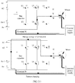
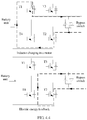
- FIG. 3.1 is a schematic diagram of V-phase charging of the charging/discharging control apparatus according to the second embodiment of the present invention.
- the control chip sends a first PWM drive signal to the electric drive circuit by using the drive circuit, and the fourth IGBT module T4 of the electric drive circuit is backward conducted (conducted from the collector to the emitter, namely, a transistor of the IGBT module is conducted).
- the motor, the fourth IGBT module T4, the terminal N, and the external power supply form an energy storage loop.
- the external power supply charges the inductor of the motor.
- the control chip controls the fourth IGBT module T4 to be disconnected, and controls the third IGBT module T3 of the electric drive circuit to be forward conducted (conducted from the emitter to the collector, namely, a diode of the IGBT module is forward conducted).
- the motor, the third IGBT module T3, the battery, the terminal N, and the external power supply form a charging loop.
- the inductor of the motor charges the battery.
- the control chip may determine information about the external power supply such as an input direction and a type based on a sampling result of the source voltage sampling circuit.
- a sampling result greater than 0 indicates that the input direction of the external power supply is a forward direction
- a sampling result less than 0 indicates that the input direction of the external power supply is a backward direction.
- the external power supply is an alternating current power supply
- a phase of a sampling result that is greater than zero degrees and less than 180 degrees indicates that the input direction of the external power supply is a forward direction
- a phase of a sampling result that is greater than 180 degrees and less than 360 degrees indicates that the input direction of the external power supply is a backward direction.
- FIG. 3.2 is a schematic diagram of V-phase discharging of the charging/discharging control apparatus according to the second embodiment of the present invention.
- the control chip sends a second PWM drive signal to the electric drive circuit by using the drive circuit, the third IGBT module T3 of the electric drive circuit is backward conducted, the external power supply, the terminal N, the battery, the third IGBT module T3, and the motor form an energy storage loop, and electric energy of the battery is transmitted to the inductor of the motor.
- the control chip When it is detected that an endpoint value of a rising edge of a V-phase inductance current of the motor reaches a target value, the control chip controls the third IGBT module T3 to be disconnected, and controls the fourth IGBT module T4 of the electric drive circuit to be forward conducted.
- the motor, the external power supply, the terminal N, and the fourth IGBT module T4 form a discharging loop.
- the inductor of the motor feeds back electric energy to the external power supply.
- control chip includes at least a sampling unit and a drive unit.
- the battery voltage sampling circuit, the charging/discharging current sampling circuit, and the source voltage sampling circuit are connected to the sampling unit.
- the drive circuit is connected to the drive unit.
- the battery may include n battery units (A1, A2, ..., An-1, An), and n is a positive integer.
- the control chip of the charging/discharging control apparatus is configured to: send the first PWM drive signal to the electric drive circuit, store electric energy of the external power supply in the inductor of the motor, and charge the battery by using the electric energy stored in the inductor of the motor; or the control chip is configured to: send the second PWM drive signal to the electric drive circuit, store the electric energy of the battery in the inductor of the motor, and feed back the electric energy to the external power supply by using the electric energy stored in the inductor of the motor. It can be learned that the charging/discharging control apparatus provided in this embodiment of the present invention implements charging and discharging control of the battery by using the electric drive circuit.
- the electric drive circuit has relatively large power, thereby increasing charging/discharging power of the charging/discharging control apparatus.
- the motor and the control chip of the charging/discharging control apparatus share the electric drive circuit, and a car charger does not need to be independently deployed, to help reduce costs of the charging/discharging control apparatus and reduce a floor area.
- FIG. 4 is a structural diagram of a charging/discharging control apparatus according to a third embodiment of the present invention.
- the charging/discharging control apparatus shown in FIG. 4 is obtained by optimizing the charging/discharging control apparatus shown in FIG. 1 .
- the charging/discharging control apparatus shown in FIG. 3 has the following differences:
- the electric drive circuit includes a U-phase electric drive circuit, a V-phase electric drive circuit, and a W-phase electric drive circuit, each of the U-phase electric drive circuit, the V-phase electric drive circuit, and the W-phase electric drive circuit includes n electric drive units, the electric drive unit includes a first connecting terminal, a second connecting terminal, a control signal connecting terminal, a positive direct current input sub-terminal, and a negative direct current input sub-terminal, and n is a positive integer.
- the battery includes U-phase batteries, V-phase batteries, and W-phase batteries
- the U-phase batteries include n battery units that are correspondingly connected to n electric drive units in the U-phase electric drive circuit
- the V-phase batteries include n battery units that are correspondingly connected to n electric drive units in the V-phase electric drive circuit
- the W-phase batteries include n battery units that are correspondingly connected to n electric drive units in the W-phase electric drive circuit.
- a first connecting terminal of a first electric drive unit in the U-phase electric drive circuit is connected to the U-phase connecting terminal of the motor, a first connecting terminal of a first electric drive unit in the V-phase electric drive circuit is connected to the V-phase connecting terminal of the motor, and a first connecting terminal of a first electric drive unit in the W-phase electric drive circuit is connected to the W-phase connecting terminal of the motor.
- a second connecting terminal of an i th electric drive unit in the U-phase electric drive circuit is connected to a first connecting terminal of an (i+1) th electric drive unit in the U-phase electric drive circuit, a positive direct current input sub-terminal of the i th electric drive unit is connected to a positive electrode of an i th battery unit in the U-phase batteries of the battery, a negative direct current input sub-terminal of the i th electric drive unit is connected to a negative electrode of the i th battery unit, and i is a positive integer less than n.
- a second connecting terminal of a j th electric drive unit in the V-phase electric drive circuit is connected to a first connecting terminal of a (j+1) th electric drive unit in the V-phase electric drive circuit, a positive direct current input sub-terminal of the j th electric drive unit is connected to a positive electrode of a j th battery unit in the V-phase batteries of the battery, a negative direct current input sub-terminal of the j th electric drive unit is connected to a negative electrode of the j th battery unit, and j is a positive integer less than n.
- a second connecting terminal of a k th electric drive unit in the W-phase electric drive circuit is connected to a first connecting terminal of a (k+1) th electric drive unit in the W-phase electric drive circuit, a positive direct current input sub-terminal of the k th electric drive unit is connected to a positive electrode of a k th battery unit in the W-phase batteries of the battery, a negative direct current input sub-terminal of the k th electric drive unit is connected to a negative electrode of the k th battery unit, and k is a positive integer less than n.
- a second connecting terminal of an n th electric drive unit in the U-phase electric drive circuit, a second connecting terminal of an n th electric drive unit in the V-phase electric drive circuit, and a second connecting terminal of an n th electric drive unit in the W-phase electric drive circuit form the terminal N of the electric drive circuit.
- a control signal connecting terminal of an electric drive unit in the U-phase electric drive circuit, a control signal connecting terminal in the V-phase electric drive circuit, and a control signal connecting terminal in the W-phase electric drive circuit are connected to the control chip.
- FIG. 4.1 is a structural diagram of an electric drive unit of the charging/discharging control apparatus according to the third embodiment of the present invention.
- the electric drive unit includes an H-bridge inverter, a bypass switch, a drive circuit, a battery voltage sampling circuit, and an electric drive unit control chip.
- the bypass switch is configured to bypass the electric drive unit when the electric drive unit is faulty.
- the H-bridge inverter includes a first insulated gate bipolar transistor IGBT module, a second IGBT module T2, a third IGBT module T3, and a fourth IGBT module T4, an emitter of the first IGBT module T1, a collector of the fourth IGBT module T4, and a first terminal of the bypass switch are connected to form the first connecting terminal of the electric drive unit, and an emitter of the third IGBT module T3, a collector of the second IGBT module T2, and a second terminal of the bypass switch are connected to form the second connecting terminal of the electric drive unit.
- the battery voltage sampling circuit is configured to detect a voltage of a battery unit connected to the electric drive unit.
- a gate electrode and the emitter of the first IGBT module T1, a gate electrode and an emitter of the second IGBT module T2, a gate electrode and the emitter of the third IGBT module T3, and a gate electrode and an emitter of the fourth IGBT module T4 are connected to the drive circuit.
- the battery voltage sampling circuit and the drive circuit are connected to the electric drive unit control chip, and the electric drive unit control chip is connected to the control chip.
- An operating principle of the charging/discharging control apparatus shown in FIG. 4 is as follows:
- FIG. 4.2 is a schematic diagram of V-phase charging of the charging/discharging control apparatus when the external power supply is forward connected to according to the third embodiment of the present invention.
- the control chip sends a first pulse width modulation PWM drive signal to the n electric drive units in the V-phase electric drive circuit of the electric drive circuit.
- a fourth IGBT module T4 of the n electric drive units is backward conducted (conducted from a collector to an emitter, namely, a transistor of the IGBT module is conducted).
- a second IGBT module T2 of the n electric drive units is forward conducted (conducted from an emitter to a collector, namely, a diode of the IGBT module is forward conducted).
- the motor, the fourth IGBT module T4 and the second IGBT module T2 of the n electric drive units, the terminal N, and the external power supply form an energy storage loop.
- the external power supply stores energy in the inductor of the motor.
- the motor, the n battery units corresponding to the n electric drive units, the first IGBT module T1 and the second IGBT module T4 of the n electric drive units, the terminal N, and the external power supply form a charging loop.
- the inductor of the motor charges the battery unit.
- FIG. 4.3 is a schematic diagram of V-phase charging of the charging/discharging control apparatus when the external power supply is backward connected to according to the third embodiment of the present invention.
- the control chip sends a first PWM drive signal to the n electric drive units in the V-phase electric drive circuit of the electric drive circuit.
- a second IGBT module T2 of the n electric drive units is backward conducted.
- a fourth IGBT module T4 of the n electric drive units is forward conducted.
- the external power supply, the terminal N, the second IGBT module T2 and the fourth IGBT module T4 of the n electric drive units, and the motor form an energy storage loop.
- the external power supply stores energy in the inductor of the motor.
- the control chip disconnects the second IGBT module T2 of the n electric drive units, and a third IGBT module T3 and the fourth IGBT module T4 of the n electric drive units are forward conducted.
- the external power supply, the third IGBT module T3 of the n electric drive units, the n battery units corresponding to the n electric drive units, the fourth IGBT module T4 of the n electric drive units, the terminal N, and the motor form a charging loop.
- the inductor of the motor charges the n battery units corresponding to the n electric drive units.
- FIG. 4.4 is a schematic diagram of V-phase discharging of the charging/discharging control apparatus when the external power supply is forward connected to according to the third embodiment of the present invention.
- the control chip sends a PWM discharging drive signal to the n electric drive units in the V-phase electric drive circuit of the drive circuit.
- a first IGBT module T1 and a second IGBT module T2 of the n electric drive units are backward conducted.
- the external power supply, the terminal N, the second IGBT module T2 of the n electric drive units, the n battery units corresponding to the n electric drive units, the first IGBT module T1 of the n electric drive units, and the motor form an energy storage loop.
- the n battery units corresponding to the n electric drive units store energy in the inductor of the motor.
- the control chip disconnects the first IGBT module T1 of the n electric drive units, and a fourth IGBT module T4 of the n electric drive units is forward conducted.
- the external power supply, the terminal N, the second IGBT module T2 of the n electric drive units, the fourth IGBT module T4, and the motor form a discharging loop.
- the inductor of the motor feeds back electric energy to the external power supply.
- FIG. 4.5 is a schematic diagram of V-phase discharging of the charging/discharging control apparatus when the external power supply is backward connected to according to the third embodiment of the present invention.
- the control chip sends a PWM discharging drive signal to the n electric drive units in the V-phase electric drive circuit of the drive circuit.
- a fourth IGBT module T4 and a third IGBT module T3 of the n electric drive units are backward conducted.
- the motor, the terminal N, the fourth IGBT module T4 of the n electric drive units, the n battery units corresponding to the n electric drive units, the third IGBT module T3 of the n electric drive units, and the external power supply form an energy storage loop.
- the n battery units corresponding to the n electric drive units store energy in the inductor of the motor.
- the control chip disconnects the third IGBT module T3 of the n electric drive units, and a second IGBT module T2 of the n electric drive units is forward conducted.
- the motor, the fourth IGBT module T4 and the second IGBT module T2 of the n electric drive units, the terminal N, and the external power supply form a discharging loop.
- the inductor of the motor feeds back electric energy to the external power supply.
- the external power supply is a direct current power supply or an alternating current power supply.
- the electric drive unit control chip includes at least a sampling unit and a drive unit.
- the battery voltage sampling circuit, the charging/discharging current sampling circuit, and the source voltage sampling circuit are connected to the sampling unit.
- the drive circuit is connected to the drive unit.
- the charging/discharging current sampling circuit detects the three-phase charging/discharging currents of the charging/discharging control apparatus by using a Hall current sensor; or the charging/discharging current sampling circuit detects the three-phase charging/discharging currents of the charging/discharging control apparatus by using a resistor and an isolation operational amplifier.
- the control chip of the charging/discharging control apparatus is configured to: send a first PWM drive signal to the electric drive circuit, store electric energy of the external power supply in the inductor of the motor, and charge the battery by using the electric energy stored in the inductor of the motor; or the control chip is configured to: send a second PWM drive signal to the electric drive circuit, store electric energy of the battery in the inductor of the motor, and feed back the electric energy to the external power supply by using the electric energy stored in the inductor of the motor.
- the charging/discharging control apparatus provided in this embodiment of the present invention implements charging and discharging control of the battery by using the electric drive circuit.
- the electric drive circuit has relatively large power, thereby increasing charging/discharging power of the charging/discharging control apparatus.
- the motor and the control chip of the charging/discharging control apparatus share the electric drive circuit, and a car charger does not need to be independently deployed, to help reduce costs of the charging/discharging control apparatus and reduce a floor area.
Landscapes
- Engineering & Computer Science (AREA)
- Power Engineering (AREA)
- Transportation (AREA)
- Mechanical Engineering (AREA)
- Life Sciences & Earth Sciences (AREA)
- Sustainable Development (AREA)
- Sustainable Energy (AREA)
- Chemical & Material Sciences (AREA)
- Combustion & Propulsion (AREA)
- Charge And Discharge Circuits For Batteries Or The Like (AREA)
- Electric Propulsion And Braking For Vehicles (AREA)
Abstract
Description
- The present invention relates to the field of circuit technologies, and in particular, to a charging/discharging control apparatus.
- Electric vehicles have advantages such as high efficiency, energy efficiency, low noise, and zero emission, and are a development trend of new energy vehicles in the future. However, promotion of the electric vehicles is still limited by endurance mileage and charging technologies. Currently, large-capacity batteries are usually used for the electric vehicles. Although the endurance mileage of the electric vehicles may be improved, a higher requirement is proposed for electric vehicle charging. Currently, there are two common charging manners: alternating current slow charging and direct current fast charging. In the alternating current slow charging manner, an alternating current is converted into a direct current by using a power conversion apparatus permanently installed inside an electric vehicle, to charge a power battery of the electric vehicle. In the direct current fast charging manner, an alternating current is converted into a direct current by using a power conversion apparatus permanently installed outside an electric vehicle, to directly charge a power battery of the electric vehicle.
- During research, the inventor of the technical solutions finds that, in the existing alternating current slow charging solution, a car charger and an electric drive power conversion apparatus are mutually independent, and consequently, limited by vehicle space, the charger has low power, low charging efficiency, and a relatively long charging time; in the direct current fast charging solution, a power conversion apparatus has high costs and a large floor area.
- The present invention discloses a charging/discharging control apparatus, to implement charging/discharging control of a battery.
- A first aspect of the present invention provides a charging/discharging control apparatus, including a motor, an electric drive circuit, a source voltage sampling circuit, a charging/discharging current sampling circuit, and a control chip, where
a U-phase connecting terminal of the motor is connected to a U-phase connecting terminal of the electric drive circuit, a V-phase connecting terminal of the motor is connected to a V-phase connecting terminal of the electric drive circuit, a W-phase connecting terminal of the motor is connected to a W-phase connecting terminal of the electric drive circuit, and a center tap of the motor is configured to connect to a first charging/discharging terminal of an external power supply;
a terminal N of the electric drive circuit is configured to connect to a second charging/discharging terminal of the external power supply, a positive direct current input terminal of the electric drive circuit is configured to connect to a positive electrode of a battery, and a negative direct current input terminal of the electric drive circuit is configured to connect to a negative electrode of the battery;
the charging/discharging current sampling circuit is configured to detect three-phase charging/discharging currents of the charging/discharging control apparatus, the source voltage sampling circuit is configured to detect a voltage of the external power supply, and the charging/discharging current sampling circuit and the source voltage sampling circuit are connected to the control chip; and
the control chip is configured to send a first pulse width modulation PWM drive signal to the electric drive circuit, and the first PWM drive signal is used to instruct the electric drive circuit to store electric energy of the external power supply in an inductor of the motor and charge the battery by using the electric energy stored in the inductor of the motor; or
the control chip is configured to send a second PWM drive signal to the electric drive circuit, and the second PWM drive signal is used to instruct the electric drive circuit to store electric energy of the battery in an inductor of the motor and feed back electric energy to the external power supply by using the electric energy stored in the inductor of the motor. - When an operating mode of the charging/discharging control apparatus is a charging mode, the control chip of the charging/discharging control apparatus obtains an input power supply type, a source voltage sampling value, and a charging current detection value, calculates the first PWM drive signal based on the input power supply type, the source voltage sampling value, an inductance value of the motor, and an error between the charging current detection value and a target charging current value, and performs closed-loop control based on the first PWM drive signal, to store the electric energy of the external power supply in the inductor of the motor and then transmit the electric energy stored in the inductor of the motor to the battery, namely, charge the battery.
- When an operating mode of the charging/discharging control apparatus is a discharging mode, the control chip of the charging/discharging control apparatus obtains an input power supply type, battery energy, feedback power, a source voltage sampling value, and a battery voltage sampling value, calculates the second PWM drive signal based on the battery energy, the feedback power, the source voltage sampling value, the battery voltage sampling value, an inductance value of the motor, and an error between a target discharging current value and a discharging current detection value, and performs closed-loop control based on the first PWM drive signal, to store the electric energy of the battery in the inductor of the motor and then transmit the electric energy stored in the inductor of the motor to the external power supply, namely, feed back the electric energy to the external power supply.
- In a possible design, the charging/discharging control apparatus further includes a battery voltage sampling circuit and a drive circuit; and
the battery voltage sampling circuit is configured to detect a voltage of the battery, the battery voltage sampling circuit is connected to the control chip, the electric drive circuit is connected to the drive circuit, and the drive circuit is connected to the control chip. - In another possible design, the electric drive circuit includes a first insulated gate bipolar transistor IGBT module, a second IGBT module, a third IGBT module, a fourth IGBT module, a fifth IGBT module, a sixth IGBT module, and a bus capacitor;
an emitter of the first IGBT module is connected to a collector of the second IGBT module to form the U-phase connecting terminal of the electric drive circuit, an emitter of the IGBT 3 is connected to a collector of the fourth IGBT module to form the V-phase connecting terminal of the electric drive circuit, and an emitter of the fifth IGBT module is connected to a collector of the sixth IGBT module to form the W-phase connecting terminal of the electric drive circuit;
a collector of the first IGBT module, a collector of the third IGBT module, a collector of the fifth IGBT module, and a positive electrode of the bus capacitor are connected to form the positive direct current input terminal of the electric drive circuit;
an emitter of the second IGBT module, an emitter of the fourth IGBT module, an emitter of the sixth IGBT module, and a negative electrode of the bus capacitor are connected to form the negative direct current input terminal and the terminal N of the electric drive circuit; and
a gate electrode and the emitter of the first IGBT module, a gate electrode and the emitter of the second IGBT module, a gate electrode and the emitter of the third IGBT module, a gate electrode and the emitter of the fourth IGBT module, a gate electrode and the emitter of the fifth IGBT module, and a gate electrode and the emitter of the sixth IGBT module are connected to the drive circuit. - It should be noted that the external power supply connected to the charging/discharging control apparatus is a direct current power supply; and the drive circuit includes a signal isolation circuit and a power amplification circuit.
- In addition, the control chip of the charging/discharging control apparatus includes at least a sampling unit and a drive unit; and
the battery voltage sampling circuit, the charging/discharging current sampling circuit, and the source voltage sampling circuit are connected to the sampling unit; and the drive circuit is connected to the drive unit. - In still another possible design, the electric drive circuit includes a U-phase electric drive circuit, a V-phase electric drive circuit, and a W-phase electric drive circuit, each of the U-phase electric drive circuit, the V-phase electric drive circuit, and the W-phase electric drive circuit includes n electric drive units, the electric drive unit includes a first connecting terminal, a second connecting terminal, a control signal connecting terminal, a positive direct current input sub-terminal, and a negative direct current input sub-terminal, and n is a positive integer;
the battery includes U-phase batteries, V-phase batteries, and W-phase batteries, the U-phase batteries include n battery units that are correspondingly connected to n electric drive units in the U-phase electric drive circuit, the V-phase batteries include n battery units that are correspondingly connected to n electric drive units in the V-phase electric drive circuit, and the W-phase batteries include n battery units that are correspondingly connected to n electric drive units in the W-phase electric drive circuit;
a first connecting terminal of a first electric drive unit in the U-phase electric drive circuit is connected to the U-phase connecting terminal of the motor, a first connecting terminal of a first electric drive unit in the V-phase electric drive circuit is connected to the V-phase connecting terminal of the motor, and a first connecting terminal of a first electric drive unit in the W-phase electric drive circuit is connected to the W-phase connecting terminal of the motor;
a second connecting terminal of an ith electric drive unit in the U-phase electric drive circuit is connected to a first connecting terminal of an (i+1)th electric drive unit in the U-phase electric drive circuit, a positive direct current input sub-terminal of the ith electric drive unit is connected to a positive electrode of an ith battery unit in the U-phase batteries of the battery, a negative direct current input sub-terminal of the ith electric drive unit is connected to a negative electrode of the ith battery unit, and i is a positive integer less than n; a second connecting terminal of a jth electric drive unit in the V-phase electric drive circuit is connected to a first connecting terminal of a (j+1)th electric drive unit in the V-phase electric drive circuit, a positive direct current input sub-terminal of the jth electric drive unit is connected to a positive electrode of a jth battery unit in the V-phase batteries of the battery, a negative direct current input sub-terminal of the jth electric drive unit is connected to a negative electrode of the jth battery unit, and j is a positive integer less than n; and a second connecting terminal of a kth electric drive unit in the W-phase electric drive circuit is connected to a first connecting terminal of a (k+1)th electric drive unit in the W-phase electric drive circuit, a positive direct current input sub-terminal of the kth electric drive unit is connected to a positive electrode of a kth battery unit in the W-phase batteries of the battery, a negative direct current input sub-terminal of the kth electric drive unit is connected to a negative electrode of the kth battery unit, and k is a positive integer less than n;
a second connecting terminal of an nth electric drive unit in the U-phase electric drive circuit, a second connecting terminal of an nth electric drive unit in the V-phase electric drive circuit, and a second connecting terminal of an nth electric drive unit in the W-phase electric drive circuit form the terminal N of the electric drive circuit; and
a control signal connecting terminal of an electric drive unit in the U-phase electric drive circuit, a control signal connecting terminal in the V-phase electric drive circuit, and a control signal connecting terminal in the W-phase electric drive circuit are connected to the control chip. - It may be understood that the electric drive unit of the charging/discharging control apparatus may specifically include an H-bridge inverter, a bypass switch, a drive circuit, a battery voltage sampling circuit, and an electric drive unit control chip;
the H-bridge inverter includes a first insulated gate bipolar transistor IGBT module, a second IGBT module, a third IGBT module, and a fourth IGBT module, an emitter of the first IGBT module, a collector of the fourth IGBT module, and a first terminal of the bypass switch are connected to form the first connecting terminal of the electric drive unit, and an emitter of the third IGBT module, a collector of the second IGBT module, and a second terminal of the bypass switch are connected to form the second connecting terminal of the electric drive unit;
the battery voltage sampling circuit is configured to detect a voltage of a battery unit connected to the electric drive unit;
a gate electrode and the emitter of the first IGBT module, a gate electrode and an emitter of the second IGBT module, a gate electrode and the emitter of the third IGBT module, and a gate electrode and an emitter of the fourth IGBT module are connected to the drive circuit; and
the battery voltage sampling circuit and the drive circuit are connected to the electric drive unit control chip, and the electric drive unit control chip is connected to the control chip. - In addition, the external power supply connected to the charging/discharging control apparatus is a direct current power supply or an alternating current power supply; and the electric drive unit control chip includes at least a sampling unit and a drive unit;
the battery voltage sampling circuit, the charging/discharging current sampling circuit, and the source voltage sampling circuit are connected to the sampling unit; and
the drive circuit is connected to the drive unit. - In some possible implementations, the charging/discharging current sampling circuit may detect the three-phase charging/discharging currents of the charging/discharging control apparatus by using a Hall current sensor; or
the charging/discharging current sampling circuit may detect the three-phase charging/discharging currents of the charging/discharging control apparatus by using a resistor and an isolation operational amplifier. - In the embodiments of the present invention, the control chip of the charging/discharging control apparatus is configured to: send the first PWM drive signal to the electric drive circuit, store the electric energy of the external power supply in the inductor of the motor, and charge the battery by using the electric energy stored in the inductor of the motor; or the control chip is configured to: send the second PWM drive signal to the electric drive circuit, store the electric energy of the battery in the inductor of the motor, and feed back the electric energy to the external power supply by using the electric energy stored in the inductor of the motor. It can be learned that the charging/discharging control apparatus provided in the embodiments of the present invention implements charging and discharging control of the battery by using the electric drive circuit. The electric drive circuit has relatively large power, thereby increasing charging/discharging power of the charging/discharging control apparatus. In addition, the motor and the control chip of the charging/discharging control apparatus share the electric drive circuit, and a car charger does not need to be independently deployed, to help reduce costs of the charging/discharging control apparatus and reduce a floor area.
- To describe the technical solutions in the embodiments of the present invention or in the prior art more clearly, the following briefly describes the accompanying drawings required for describing the embodiments. Apparently, the accompanying drawings in the following description show merely some embodiments of the present invention, and a person of ordinary skill in the art may still derive other drawings from these accompanying drawings without creative efforts.
-
FIG. 1 is a schematic structural diagram of a charging/discharging control apparatus according to a first embodiment of the present invention; -
FIG. 2 is a schematic structural diagram of a charging/discharging control apparatus according to a second embodiment of the present invention; -
FIG. 3 is a schematic structural diagram of another charging/discharging control apparatus according to a second embodiment of the present invention; -
FIG. 3.1 is a schematic diagram of V-phase charging of a charging/discharging control apparatus according to a second embodiment of the present invention; -
FIG. 3.2 is a schematic diagram of V-phase discharging of a charging/discharging control apparatus according to a second embodiment of the present invention; -
FIG. 4 is a schematic structural diagram of a charging/discharging control apparatus according to a third embodiment of the present invention; -
FIG. 4.1 is a schematic structural diagram of an electric drive unit of a charging/discharging control apparatus according to a third embodiment of the present invention; -
FIG. 4.2 is a schematic diagram of V-phase charging of a charging/discharging control apparatus when an external power supply is forward connected to according to a third embodiment of the present invention; -
FIG. 4.3 is a schematic diagram of V-phase charging of a charging/discharging control apparatus when an external power supply is backward connected to according to a third embodiment of the present invention; -
FIG. 4.4 is a schematic diagram of V-phase discharging of a charging/discharging control apparatus when an external power supply is forward connected to according to a third embodiment of the present invention; and -
FIG. 4.5 is a schematic diagram of V-phase discharging of a charging/discharging control apparatus when an external power supply is backward connected to according to a third embodiment of the present invention. - The following clearly and completely describes the technical solutions in the embodiments of the present invention with reference to the accompanying drawings in the embodiments of the present invention. Apparently, the described embodiments are merely some but not all of the embodiments of the present invention. All other embodiments obtained by a person of ordinary skill in the art based on the embodiments of the present invention without creative efforts shall fall within the protection scope of the present invention.
- Currently, large-capacity batteries are usually used for electric vehicles. Currently, there are two common charging manners: alternating current slow charging and direct current fast charging. In the alternating current slow charging manner, an alternating current is converted into a direct current by using a power conversion apparatus permanently installed inside an electric vehicle, to charge a power battery of the electric vehicle. In this manner, a car charger and an electric drive power conversion circuit are mutually independent. Limited by vehicle space, the charger has low power and a relatively long charging time. In the direct current fast charging manner, an alternating current is converted into a direct current by using a power conversion apparatus permanently installed outside an electric vehicle, to directly charge a power battery of the electric vehicle. In this manner, the power conversion apparatus has high costs and a large floor area.
- To resolve the foregoing technical problem, this application discloses a charging/discharging control apparatus. In a charging mode, the charging/discharging control apparatus stores electric energy of an external power supply by using an inductor of a motor, and transmits, by using an electric drive circuit, the electric energy stored in the inductor to a battery. In a discharging mode, the charging/discharging control apparatus stores electric energy of a battery by using an inductor of a motor, and then feeds back, by using an electric drive circuit, the electric energy stored in the inductor to an external power supply. In this way, the charging/discharging control apparatus implements charging and discharging control of the battery by using the electric drive circuit. Because the electric drive circuit has relatively large power, charging/discharging power may be increased. In addition, the motor and a control chip of the charging/discharging control apparatus share the electric drive circuit, and a car charger does not need to be independently deployed, to help reduce costs of the charging/discharging control apparatus and reduce a floor area.
- It should be noted that the charging/discharging control apparatus described in the embodiments of the present invention may be applied to a mobile vehicle such as a car, a truck, a motorcycle, a bus, a ship, a plane, a helicopter, a mower, a snow clearer, a station wagon, an amusement park vehicle, an agricultural device, a construction device, a streetcar, or a golf cart. In addition, the charging/discharging control apparatus provided in the present invention may also be used for a robot apparatus. Details are separately described below.
- Referring to
FIG. 1, FIG. 1 is a structural diagram of a charging/discharging control apparatus according toEmbodiment 1 of the present invention. As shown inFIG. 1 , the charging/discharging control apparatus may include a motor, an electric drive circuit, a source voltage sampling circuit, a charging/discharging current sampling circuit, and a control chip. - A U-phase connecting terminal of the motor is connected to a U-phase connecting terminal of the electric drive circuit, a V-phase connecting terminal of the motor is connected to a V-phase connecting terminal of the electric drive circuit, a W-phase connecting terminal of the motor is connected to a W-phase connecting terminal of the electric drive circuit, and a center tap of the motor is configured to connect to a first charging/discharging terminal of an external power supply.
- A terminal N of the electric drive circuit is configured to connect to a second charging/discharging terminal of the external power supply, a positive direct current input terminal of the electric drive circuit is configured to connect to a positive electrode of a battery, and a negative direct current input terminal of the electric drive circuit is configured to connect to a negative electrode of the battery.
- The charging/discharging current sampling circuit is configured to detect three-phase charging/discharging currents of the charging/discharging control apparatus, the source voltage sampling circuit is configured to detect a voltage of the external power supply, and the charging/discharging current sampling circuit and the source voltage sampling circuit are connected to the control chip.
- The control chip is configured to send a first pulse width modulation PWM drive signal to the electric drive circuit, and the first PWM drive signal is used to instruct the electric drive circuit to store electric energy of the external power supply in an inductor of the motor and charge the battery by using the electric energy stored in the inductor of the motor.
- Alternatively, the control chip is configured to send a second PWM drive signal to the electric drive circuit, and the second PWM drive signal is used to instruct the electric drive circuit to store electric energy of the battery in an inductor of the motor and feed back electric energy to the external power supply by using the electric energy stored in the inductor of the motor.
- An operating principle of the charging/discharging control apparatus shown in
FIG. 1 is as follows: - When an operating mode of the charging/discharging control apparatus is set to a charging mode, the control chip of the charging/discharging control apparatus obtains an input power supply type, a source voltage sampling value, a charging current detection value, and a battery voltage sampling value, calculates the first PWM drive signal based on the input power supply type, the source voltage sampling value, the battery voltage sampling value, an inductance value of the motor, and an error between a target charging current value and the charging current detection value, and performs closed-loop control based on the first PWM drive signal, to store the electric energy of the external power supply in the inductor of the motor and then transmit the electric energy stored in the inductor of the motor to the battery, namely, charge the battery.
- When an operating mode of the charging/discharging control apparatus is set to a discharging mode, the control chip of the charging/discharging control apparatus obtains an input power supply type, battery energy, feedback power, a source voltage sampling value, and a battery voltage sampling value, calculates the second PWM drive signal based on the battery energy, the feedback power, the source voltage sampling value, the battery voltage sampling value, an inductance value of the motor, and an error between a target discharging current value and a discharging current detection value, and performs closed-loop control based on the second PWM drive signal, to store the electric energy of the battery in the inductor of the motor and then transmit the electric energy stored in the inductor of the motor to the external power supply, namely, feed back the electric energy to the external power supply.
- Switchover of the operating mode of the charging/discharging control apparatus may be controlled in a hardware manner, or may be controlled in a software manner, or may be controlled by using a combination of hardware and software. For example, switchover between the charging mode and the discharging mode of the charging/discharging control apparatus may be controlled by using a high-low level conversion circuit. The switchover control of the operating mode of the charging/discharging control apparatus is not uniquely limited in this embodiment of the present invention.
- In the charging/discharging control apparatus described in
FIG. 1 , the control chip of the charging/discharging control apparatus is configured to: send the first PWM drive signal to the electric drive circuit, store the electric energy of the external power supply in the inductor of the motor, and charge the battery by using the electric energy stored in the inductor of the motor; or the control chip is configured to: send the second PWM drive signal to the electric drive circuit, store the electric energy of the battery in the inductor of the motor, and feed back the electric energy to the external power supply by using the electric energy stored in the inductor of the motor. It can be learned that the charging/discharging control apparatus provided in this embodiment of the present invention implements charging and discharging control of the battery by using the electric drive circuit. The electric drive circuit has relatively large power, thereby increasing charging/discharging power of the charging/discharging control apparatus. In addition, the motor and the control chip of the charging/discharging control apparatus share the electric drive circuit, and a car charger does not need to be independently deployed, to help reduce costs of the charging/discharging control apparatus and reduce a floor area. - Optionally, in this embodiment of the present invention, the charging/discharging current sampling circuit detects the three-phase charging/discharging currents of the charging/discharging control apparatus by using a Hall current sensor.
- Optionally, in this embodiment of the present invention, the charging/discharging current sampling circuit detects the three-phase charging/discharging currents of the charging/discharging control apparatus by using a resistor and an isolation operational amplifier.
- It may be understood that there may be various specific implementations of the charging/discharging current sampling circuit and the source voltage sampling circuit of the charging/discharging control apparatus, and this is not uniquely limited in this embodiment of the present invention.
- Referring to
FIG. 2, FIG. 2 is a structural diagram of a charging/discharging control apparatus according to a second embodiment of the present invention. The charging/discharging control apparatus shown inFIG. 2 is obtained by optimizing the charging/discharging control apparatus shown inFIG. 1 . Compared with the charging/discharging control apparatus shown inFIG. 1 , the charging/discharging control apparatus shown inFIG. 2 further includes a battery voltage sampling circuit and a drive circuit. - The battery voltage sampling circuit is configured to detect a voltage of the battery, and the battery voltage sampling circuit is connected to the control chip.
- The electric drive circuit is connected to the drive circuit, and the drive circuit is connected to the control chip.
- Optionally, in this embodiment of the present invention, referring to
FIG. 3, FIG. 3 is a structural diagram of another charging/discharging control apparatus according to the second embodiment of the present invention. - The electric drive circuit includes a first insulated gate bipolar transistor IGBT (Insulated Gate Bipolar Transistor) module, a second IGBT module T2, a third IGBT module T3, a fourth IGBT module T4, a fifth IGBT module T5, a sixth IGBT module T6, and a bus capacitor.
- An emitter of the first IGBT module T1 is connected to a collector of the second IGBT module T2 to form the U-phase connecting terminal of the electric drive circuit, an emitter of the IGBT 3 is connected to a collector of the fourth IGBT module T4 to form the V-phase connecting terminal of the electric drive circuit, and an emitter of the fifth IGBT module T5 is connected to a collector of the sixth IGBT module T6 to form the W-phase connecting terminal of the electric drive circuit.
- A collector of the first IGBT module T1, a collector of the third IGBT module T3, a collector of the fifth IGBT module T5, and a positive electrode of the bus capacitor are connected to form the positive direct current input terminal of the electric drive circuit.
- An emitter of the second IGBT module T2, an emitter of the fourth IGBT module T4, an emitter of the sixth IGBT module T6, and a negative electrode of the bus capacitor are connected to form the negative direct current input terminal and the terminal N of the electric drive circuit.
- A gate electrode and the emitter of the first IGBT module T1, a gate electrode and the emitter of the second IGBT module T2, a gate electrode and the emitter of the third IGBT module T3, a gate electrode and the emitter of the fourth IGBT module T4, a gate electrode and the emitter of the fifth IGBT module T5, and a gate electrode and the emitter of the sixth IGBT module T6 are connected to the drive circuit.
- Optionally, in this embodiment of the present invention, the external power supply is a direct current power supply.
- The drive circuit includes a signal isolation circuit and a power amplification circuit.
- The following describes in detail an operating principle of the charging/discharging control apparatus provided in this embodiment of the present invention with reference to a schematic diagram:
- Referring to
FIG. 3.1, FIG. 3.1 is a schematic diagram of V-phase charging of the charging/discharging control apparatus according to the second embodiment of the present invention. When an operating mode of the charging/discharging control apparatus is a charging mode, and a direction of the external power supply is a forward direction (a forward direction of the direct current power supply), the control chip sends a first PWM drive signal to the electric drive circuit by using the drive circuit, and the fourth IGBT module T4 of the electric drive circuit is backward conducted (conducted from the collector to the emitter, namely, a transistor of the IGBT module is conducted). In this case, the motor, the fourth IGBT module T4, the terminal N, and the external power supply form an energy storage loop. The external power supply charges the inductor of the motor. When it is detected that an endpoint value of a rising edge of a V-phase inductance current of the motor reaches a target value, the control chip controls the fourth IGBT module T4 to be disconnected, and controls the third IGBT module T3 of the electric drive circuit to be forward conducted (conducted from the emitter to the collector, namely, a diode of the IGBT module is forward conducted). The motor, the third IGBT module T3, the battery, the terminal N, and the external power supply form a charging loop. The inductor of the motor charges the battery. - The control chip may determine information about the external power supply such as an input direction and a type based on a sampling result of the source voltage sampling circuit. When the external power supply is a direct current power supply, a sampling result greater than 0 indicates that the input direction of the external power supply is a forward direction, and a sampling result less than 0 indicates that the input direction of the external power supply is a backward direction. When the external power supply is an alternating current power supply, a phase of a sampling result that is greater than zero degrees and less than 180 degrees indicates that the input direction of the external power supply is a forward direction, and a phase of a sampling result that is greater than 180 degrees and less than 360 degrees indicates that the input direction of the external power supply is a backward direction.
- Referring to
FIG. 3.2, FIG. 3.2 is a schematic diagram of V-phase discharging of the charging/discharging control apparatus according to the second embodiment of the present invention. When an operating mode of the charging/discharging control apparatus is a discharging mode, and a direction of the external power supply is a forward direction (a forward direction of the direct current power supply), the control chip sends a second PWM drive signal to the electric drive circuit by using the drive circuit, the third IGBT module T3 of the electric drive circuit is backward conducted, the external power supply, the terminal N, the battery, the third IGBT module T3, and the motor form an energy storage loop, and electric energy of the battery is transmitted to the inductor of the motor. When it is detected that an endpoint value of a rising edge of a V-phase inductance current of the motor reaches a target value, the control chip controls the third IGBT module T3 to be disconnected, and controls the fourth IGBT module T4 of the electric drive circuit to be forward conducted. The motor, the external power supply, the terminal N, and the fourth IGBT module T4 form a discharging loop. The inductor of the motor feeds back electric energy to the external power supply. - Optionally, in this embodiment of the present invention, the control chip includes at least a sampling unit and a drive unit.
- The battery voltage sampling circuit, the charging/discharging current sampling circuit, and the source voltage sampling circuit are connected to the sampling unit.
- The drive circuit is connected to the drive unit.
- The battery may include n battery units (A1, A2, ..., An-1, An), and n is a positive integer.
- In the charging/discharging control apparatus described in
FIG. 2 orFIG. 3 , the control chip of the charging/discharging control apparatus is configured to: send the first PWM drive signal to the electric drive circuit, store electric energy of the external power supply in the inductor of the motor, and charge the battery by using the electric energy stored in the inductor of the motor; or the control chip is configured to: send the second PWM drive signal to the electric drive circuit, store the electric energy of the battery in the inductor of the motor, and feed back the electric energy to the external power supply by using the electric energy stored in the inductor of the motor. It can be learned that the charging/discharging control apparatus provided in this embodiment of the present invention implements charging and discharging control of the battery by using the electric drive circuit. The electric drive circuit has relatively large power, thereby increasing charging/discharging power of the charging/discharging control apparatus. In addition, the motor and the control chip of the charging/discharging control apparatus share the electric drive circuit, and a car charger does not need to be independently deployed, to help reduce costs of the charging/discharging control apparatus and reduce a floor area. - Referring to
FIG. 4, FIG. 4 is a structural diagram of a charging/discharging control apparatus according to a third embodiment of the present invention. The charging/discharging control apparatus shown inFIG. 4 is obtained by optimizing the charging/discharging control apparatus shown inFIG. 1 . In comparison with the charging/discharging control apparatus shown inFIG. 1 , the charging/discharging control apparatus shown inFIG. 3 has the following differences: - The electric drive circuit includes a U-phase electric drive circuit, a V-phase electric drive circuit, and a W-phase electric drive circuit, each of the U-phase electric drive circuit, the V-phase electric drive circuit, and the W-phase electric drive circuit includes n electric drive units, the electric drive unit includes a first connecting terminal, a second connecting terminal, a control signal connecting terminal, a positive direct current input sub-terminal, and a negative direct current input sub-terminal, and n is a positive integer.
- The battery includes U-phase batteries, V-phase batteries, and W-phase batteries, the U-phase batteries include n battery units that are correspondingly connected to n electric drive units in the U-phase electric drive circuit, the V-phase batteries include n battery units that are correspondingly connected to n electric drive units in the V-phase electric drive circuit, and the W-phase batteries include n battery units that are correspondingly connected to n electric drive units in the W-phase electric drive circuit.
- A first connecting terminal of a first electric drive unit in the U-phase electric drive circuit is connected to the U-phase connecting terminal of the motor, a first connecting terminal of a first electric drive unit in the V-phase electric drive circuit is connected to the V-phase connecting terminal of the motor, and a first connecting terminal of a first electric drive unit in the W-phase electric drive circuit is connected to the W-phase connecting terminal of the motor.
- A second connecting terminal of an ith electric drive unit in the U-phase electric drive circuit is connected to a first connecting terminal of an (i+1)th electric drive unit in the U-phase electric drive circuit, a positive direct current input sub-terminal of the ith electric drive unit is connected to a positive electrode of an ith battery unit in the U-phase batteries of the battery, a negative direct current input sub-terminal of the ith electric drive unit is connected to a negative electrode of the ith battery unit, and i is a positive integer less than n. A second connecting terminal of a jth electric drive unit in the V-phase electric drive circuit is connected to a first connecting terminal of a (j+1)th electric drive unit in the V-phase electric drive circuit, a positive direct current input sub-terminal of the jth electric drive unit is connected to a positive electrode of a jth battery unit in the V-phase batteries of the battery, a negative direct current input sub-terminal of the jth electric drive unit is connected to a negative electrode of the jth battery unit, and j is a positive integer less than n. A second connecting terminal of a kth electric drive unit in the W-phase electric drive circuit is connected to a first connecting terminal of a (k+1)th electric drive unit in the W-phase electric drive circuit, a positive direct current input sub-terminal of the kth electric drive unit is connected to a positive electrode of a kth battery unit in the W-phase batteries of the battery, a negative direct current input sub-terminal of the kth electric drive unit is connected to a negative electrode of the kth battery unit, and k is a positive integer less than n.
- A second connecting terminal of an nth electric drive unit in the U-phase electric drive circuit, a second connecting terminal of an nth electric drive unit in the V-phase electric drive circuit, and a second connecting terminal of an nth electric drive unit in the W-phase electric drive circuit form the terminal N of the electric drive circuit.
- A control signal connecting terminal of an electric drive unit in the U-phase electric drive circuit, a control signal connecting terminal in the V-phase electric drive circuit, and a control signal connecting terminal in the W-phase electric drive circuit are connected to the control chip.
- Optionally, referring to
FIG. 4.1, FIG. 4.1 is a structural diagram of an electric drive unit of the charging/discharging control apparatus according to the third embodiment of the present invention. - The electric drive unit includes an H-bridge inverter, a bypass switch, a drive circuit, a battery voltage sampling circuit, and an electric drive unit control chip. The bypass switch is configured to bypass the electric drive unit when the electric drive unit is faulty.
- The H-bridge inverter includes a first insulated gate bipolar transistor IGBT module, a second IGBT module T2, a third IGBT module T3, and a fourth IGBT module T4, an emitter of the first IGBT module T1, a collector of the fourth IGBT module T4, and a first terminal of the bypass switch are connected to form the first connecting terminal of the electric drive unit, and an emitter of the third IGBT module T3, a collector of the second IGBT module T2, and a second terminal of the bypass switch are connected to form the second connecting terminal of the electric drive unit.
- The battery voltage sampling circuit is configured to detect a voltage of a battery unit connected to the electric drive unit.
- A gate electrode and the emitter of the first IGBT module T1, a gate electrode and an emitter of the second IGBT module T2, a gate electrode and the emitter of the third IGBT module T3, and a gate electrode and an emitter of the fourth IGBT module T4 are connected to the drive circuit.
- The battery voltage sampling circuit and the drive circuit are connected to the electric drive unit control chip, and the electric drive unit control chip is connected to the control chip.
- The following describes in detail an operating principle of the charging/discharging control apparatus provided in this embodiment of the present invention with reference to a schematic diagram:
- An operating principle of the charging/discharging control apparatus shown in
FIG. 4 is as follows: - Referring to
FIG. 4.2, FIG. 4.2 is a schematic diagram of V-phase charging of the charging/discharging control apparatus when the external power supply is forward connected to according to the third embodiment of the present invention. When an operating mode of the charging/discharging control apparatus is a charging mode, and a direction of the external power supply is a forward direction, the control chip sends a first pulse width modulation PWM drive signal to the n electric drive units in the V-phase electric drive circuit of the electric drive circuit. A fourth IGBT module T4 of the n electric drive units is backward conducted (conducted from a collector to an emitter, namely, a transistor of the IGBT module is conducted). A second IGBT module T2 of the n electric drive units is forward conducted (conducted from an emitter to a collector, namely, a diode of the IGBT module is forward conducted). The motor, the fourth IGBT module T4 and the second IGBT module T2 of the n electric drive units, the terminal N, and the external power supply form an energy storage loop. The external power supply stores energy in the inductor of the motor. When it is detected that an endpoint value of a rising edge of a V-phase inductance current of the motor reaches a target value, the control chip disconnects the fourth IGBT module T4 of the n electric drive units, and a first IGBT module T1 and the second IGBT module T2 of the n electric drive units are forward conducted. The motor, the n battery units corresponding to the n electric drive units, the first IGBT module T1 and the second IGBT module T4 of the n electric drive units, the terminal N, and the external power supply form a charging loop. The inductor of the motor charges the battery unit. - Referring to
FIG. 4.3, FIG. 4.3 is a schematic diagram of V-phase charging of the charging/discharging control apparatus when the external power supply is backward connected to according to the third embodiment of the present invention. When an operating mode of the charging/discharging control apparatus is a charging mode, and a direction of the external power supply is a backward direction, the control chip sends a first PWM drive signal to the n electric drive units in the V-phase electric drive circuit of the electric drive circuit. A second IGBT module T2 of the n electric drive units is backward conducted. A fourth IGBT module T4 of the n electric drive units is forward conducted. The external power supply, the terminal N, the second IGBT module T2 and the fourth IGBT module T4 of the n electric drive units, and the motor form an energy storage loop. The external power supply stores energy in the inductor of the motor. When it is detected that an endpoint value of a rising edge of a V-phase inductance current of the motor reaches a target value, the control chip disconnects the second IGBT module T2 of the n electric drive units, and a third IGBT module T3 and the fourth IGBT module T4 of the n electric drive units are forward conducted. The external power supply, the third IGBT module T3 of the n electric drive units, the n battery units corresponding to the n electric drive units, the fourth IGBT module T4 of the n electric drive units, the terminal N, and the motor form a charging loop. The inductor of the motor charges the n battery units corresponding to the n electric drive units. - Referring to
FIG. 4.4, FIG. 4.4 is a schematic diagram of V-phase discharging of the charging/discharging control apparatus when the external power supply is forward connected to according to the third embodiment of the present invention. When an operating mode of the charging/discharging control apparatus is a discharging mode, and a direction of the external power supply is a forward direction, the control chip sends a PWM discharging drive signal to the n electric drive units in the V-phase electric drive circuit of the drive circuit. A first IGBT module T1 and a second IGBT module T2 of the n electric drive units are backward conducted. The external power supply, the terminal N, the second IGBT module T2 of the n electric drive units, the n battery units corresponding to the n electric drive units, the first IGBT module T1 of the n electric drive units, and the motor form an energy storage loop. The n battery units corresponding to the n electric drive units store energy in the inductor of the motor. When it is detected that an endpoint value of a rising edge of a V-phase inductance current of the motor reaches a target value, the control chip disconnects the first IGBT module T1 of the n electric drive units, and a fourth IGBT module T4 of the n electric drive units is forward conducted. The external power supply, the terminal N, the second IGBT module T2 of the n electric drive units, the fourth IGBT module T4, and the motor form a discharging loop. The inductor of the motor feeds back electric energy to the external power supply. - Referring to
FIG. 4.5, FIG. 4.5 is a schematic diagram of V-phase discharging of the charging/discharging control apparatus when the external power supply is backward connected to according to the third embodiment of the present invention. When an operating mode of the charging/discharging control apparatus is a discharging mode, and a direction of the external power supply is a backward direction, the control chip sends a PWM discharging drive signal to the n electric drive units in the V-phase electric drive circuit of the drive circuit. A fourth IGBT module T4 and a third IGBT module T3 of the n electric drive units are backward conducted. The motor, the terminal N, the fourth IGBT module T4 of the n electric drive units, the n battery units corresponding to the n electric drive units, the third IGBT module T3 of the n electric drive units, and the external power supply form an energy storage loop. The n battery units corresponding to the n electric drive units store energy in the inductor of the motor. When it is detected that an endpoint value of a rising edge of a V-phase inductance current of the motor reaches a target value, the control chip disconnects the third IGBT module T3 of the n electric drive units, and a second IGBT module T2 of the n electric drive units is forward conducted. The motor, the fourth IGBT module T4 and the second IGBT module T2 of the n electric drive units, the terminal N, and the external power supply form a discharging loop. The inductor of the motor feeds back electric energy to the external power supply. - Optionally, in this embodiment of the present invention, the external power supply is a direct current power supply or an alternating current power supply.
- The electric drive unit control chip includes at least a sampling unit and a drive unit.
- The battery voltage sampling circuit, the charging/discharging current sampling circuit, and the source voltage sampling circuit are connected to the sampling unit.
- The drive circuit is connected to the drive unit.
- Optionally, in this embodiment of the present invention, the charging/discharging current sampling circuit detects the three-phase charging/discharging currents of the charging/discharging control apparatus by using a Hall current sensor; or
the charging/discharging current sampling circuit detects the three-phase charging/discharging currents of the charging/discharging control apparatus by using a resistor and an isolation operational amplifier. - In the charging/discharging control apparatus described in
FIG. 4 , the control chip of the charging/discharging control apparatus is configured to: send a first PWM drive signal to the electric drive circuit, store electric energy of the external power supply in the inductor of the motor, and charge the battery by using the electric energy stored in the inductor of the motor; or the control chip is configured to: send a second PWM drive signal to the electric drive circuit, store electric energy of the battery in the inductor of the motor, and feed back the electric energy to the external power supply by using the electric energy stored in the inductor of the motor. The charging/discharging control apparatus provided in this embodiment of the present invention implements charging and discharging control of the battery by using the electric drive circuit. The electric drive circuit has relatively large power, thereby increasing charging/discharging power of the charging/discharging control apparatus. In addition, the motor and the control chip of the charging/discharging control apparatus share the electric drive circuit, and a car charger does not need to be independently deployed, to help reduce costs of the charging/discharging control apparatus and reduce a floor area. - The charging/discharging control apparatus provided in the embodiments of the present invention is described in detail above. In this specification, specific examples are used to describe the principle and implementations of the present invention. The descriptions of the foregoing embodiments are merely intended to help understand the method and core idea of the present invention. In addition, with respect to the implementations and the application scope, modifications may be made by a person of ordinary skill in the art based on the idea of the present invention. Therefore, this specification shall not be construed as a limitation on the present invention.
Claims (10)
- A charging/discharging control apparatus, comprising a motor, an electric drive circuit, a source voltage sampling circuit, a charging/discharging current sampling circuit, and a control chip, wherein
a U-phase connecting terminal of the motor is connected to a U-phase connecting terminal of the electric drive circuit, a V-phase connecting terminal of the motor is connected to a V-phase connecting terminal of the electric drive circuit, a W-phase connecting terminal of the motor is connected to a W-phase connecting terminal of the electric drive circuit, and a center tap of the motor is configured to connect to a first charging/discharging terminal of an external power supply;
a terminal N of the electric drive circuit is configured to connect to a second charging/discharging terminal of the external power supply, a positive direct current input terminal of the electric drive circuit is configured to connect to a positive electrode of a battery, and a negative direct current input terminal of the electric drive circuit is configured to connect to a negative electrode of the battery;
the charging/discharging current sampling circuit is configured to detect three-phase charging/discharging currents of the charging/discharging control apparatus, the source voltage sampling circuit is configured to detect a voltage of the external power supply, and the charging/discharging current sampling circuit and the source voltage sampling circuit are connected to the control chip; and
the control chip is configured to send a first pulse width modulation PWM drive signal to the electric drive circuit, and the first PWM drive signal is used to instruct the electric drive circuit to store electric energy of the external power supply in an inductor of the motor and charge the battery by using the electric energy stored in the inductor of the motor; or
the control chip is configured to send a second PWM drive signal to the electric drive circuit, and the second PWM drive signal is used to instruct the electric drive circuit to store electric energy of the battery in an inductor of the motor and feed back electric energy to the external power supply by using the electric energy stored in the inductor of the motor. - The charging/discharging control apparatus according to claim 1, wherein
the charging/discharging control apparatus further comprises a battery voltage sampling circuit and a drive circuit;
the battery voltage sampling circuit is configured to detect a voltage of the battery, and the battery voltage sampling circuit is connected to the control chip; and
the electric drive circuit is connected to the drive circuit, and the drive circuit is connected to the control chip. - The charging/discharging control apparatus according to claim 1 or 2, wherein
the electric drive circuit comprises a first insulated gate bipolar transistor IGBT module, a second IGBT module, a third IGBT module, a fourth IGBT module, a fifth IGBT module, a sixth IGBT module, and a bus capacitor;
an emitter of the first IGBT module is connected to a collector of the second IGBT module to form the U-phase connecting terminal of the electric drive circuit, an emitter of the IGBT 3 is connected to a collector of the fourth IGBT module to form the V-phase connecting terminal of the electric drive circuit, and an emitter of the fifth IGBT module is connected to a collector of the sixth IGBT module to form the W-phase connecting terminal of the electric drive circuit;
a collector of the first IGBT module, a collector of the third IGBT module, a collector of the fifth IGBT module, and a positive electrode of the bus capacitor are connected to form the positive direct current input terminal of the electric drive circuit;
an emitter of the second IGBT module, an emitter of the fourth IGBT module, an emitter of the sixth IGBT module, and a negative electrode of the bus capacitor are connected to form the negative direct current input terminal and the terminal N of the electric drive circuit; and
a gate electrode and the emitter of the first IGBT module, a gate electrode and the emitter of the second IGBT module, a gate electrode and the emitter of the third IGBT module, a gate electrode and the emitter of the fourth IGBT module, a gate electrode and the emitter of the fifth IGBT module, and a gate electrode and the emitter of the sixth IGBT module are connected to the drive circuit. - The charging/discharging control apparatus according to claim 2 or 3, wherein
the external power supply is a direct current power supply; and
the drive circuit comprises a signal isolation circuit and a power amplification circuit. - The charging/discharging control apparatus according to any one of claims 2 to 4, wherein
the control chip comprises at least a sampling unit and a drive unit;
the battery voltage sampling circuit, the charging/discharging current sampling circuit, and the source voltage sampling circuit are connected to the sampling unit; and
the drive circuit is connected to the drive unit. - The charging/discharging control apparatus according to claim 1, wherein
the electric drive circuit comprises a U-phase electric drive circuit, a V-phase electric drive circuit, and a W-phase electric drive circuit, each of the U-phase electric drive circuit, the V-phase electric drive circuit, and the W-phase electric drive circuit comprises n electric drive units, the electric drive unit comprises a first connecting terminal, a second connecting terminal, a control signal connecting terminal, a positive direct current input sub-terminal, and a negative direct current input sub-terminal, and n is a positive integer;
the battery comprises U-phase batteries, V-phase batteries, and W-phase batteries, the U-phase batteries comprise n battery units that are correspondingly connected to n electric drive units in the U-phase electric drive circuit, the V-phase batteries comprise n battery units that are correspondingly connected to n electric drive units in the V-phase electric drive circuit, and the W-phase batteries comprise n battery units that are correspondingly connected to n electric drive units in the W-phase electric drive circuit;
a first connecting terminal of a first electric drive unit in the U-phase electric drive circuit is connected to the U-phase connecting terminal of the motor, a first connecting terminal of a first electric drive unit in the V-phase electric drive circuit is connected to the V-phase connecting terminal of the motor, and a first connecting terminal of a first electric drive unit in the W-phase electric drive circuit is connected to the W-phase connecting terminal of the motor;
a second connecting terminal of an ith electric drive unit in the U-phase electric drive circuit is connected to a first connecting terminal of an (i+1)th electric drive unit in the U-phase electric drive circuit, a positive direct current input sub-terminal of the ith electric drive unit is connected to a positive electrode of an ith battery unit in the U-phase batteries of the battery, a negative direct current input sub-terminal of the ith electric drive unit is connected to a negative electrode of the ith battery unit, and i is a positive integer less than n;
a second connecting terminal of a jth electric drive unit in the V-phase electric drive circuit is connected to a first connecting terminal of a (j+1)th electric drive unit in the V-phase electric drive circuit, a positive direct current input sub-terminal of the jth electric drive unit is connected to a positive electrode of a jth battery unit in the V-phase batteries of the battery, a negative direct current input sub-terminal of the jth electric drive unit is connected to a negative electrode of the jth battery unit, and j is a positive integer less than n;
a second connecting terminal of a kth electric drive unit in the W-phase electric drive circuit is connected to a first connecting terminal of a (k+1)th electric drive unit in the W-phase electric drive circuit, a positive direct current input sub-terminal of the kth electric drive unit is connected to a positive electrode of a kth battery unit in the W-phase batteries of the battery, a negative direct current input sub-terminal of the kth electric drive unit is connected to a negative electrode of the kth battery unit, and k is a positive integer less than n;
a second connecting terminal of an nth electric drive unit in the U-phase electric drive circuit, a second connecting terminal of an nth electric drive unit in the V-phase electric drive circuit, and a second connecting terminal of an nth electric drive unit in the W-phase electric drive circuit form the terminal N of the electric drive circuit; and
a control signal connecting terminal of an electric drive unit in the U-phase electric drive circuit, a control signal connecting terminal in the V-phase electric drive circuit, and a control signal connecting terminal in the W-phase electric drive circuit are connected to the control chip. - The charging/discharging control apparatus according to claim 6, wherein
the electric drive unit comprises an H-bridge inverter, a bypass switch, a drive circuit, a battery voltage sampling circuit, and an electric drive unit control chip;
the H-bridge inverter comprises a first insulated gate bipolar transistor IGBT module, a second IGBT module, a third IGBT module, and a fourth IGBT module, an emitter of the first IGBT module, a collector of the fourth IGBT module, and a first terminal of the bypass switch are connected to form the first connecting terminal of the electric drive unit, and an emitter of the third IGBT module, a collector of the second IGBT module, and a second terminal of the bypass switch are connected to form the second connecting terminal of the electric drive unit;
the battery voltage sampling circuit is configured to detect a voltage of a battery unit connected to the electric drive unit;
a gate electrode and the emitter of the first IGBT module, a gate electrode and an emitter of the second IGBT module, a gate electrode and the emitter of the third IGBT module, and a gate electrode and an emitter of the fourth IGBT module are connected to the drive circuit; and
the battery voltage sampling circuit and the drive circuit are connected to the electric drive unit control chip, and the electric drive unit control chip is connected to the control chip. - The charging/discharging control apparatus according to claim 6 or 7, wherein
the external power supply is a direct current power supply or an alternating current power supply;
the electric drive unit control chip comprises at least a sampling unit and a drive unit;
the battery voltage sampling circuit, the charging/discharging current sampling circuit, and the source voltage sampling circuit are connected to the sampling unit; and
the drive circuit is connected to the drive unit. - The charging/discharging control apparatus according to any one of claims 1 to 8, wherein
the charging/discharging current sampling circuit detects the three-phase charging/discharging currents of the charging/discharging control apparatus by using a Hall current sensor. - The charging/discharging control apparatus according to any one of claims 1 to 8, wherein
the charging/discharging current sampling circuit detects the three-phase charging/discharging currents of the charging/discharging control apparatus by using a resistor and an isolation operational amplifier.
Applications Claiming Priority (2)
| Application Number | Priority Date | Filing Date | Title |
|---|---|---|---|
| CN201610042115.6A CN106992558A (en) | 2016-01-21 | 2016-01-21 | A charging and discharging control device |
| PCT/CN2017/071120 WO2017124971A1 (en) | 2016-01-21 | 2017-01-13 | Charging/discharging control device |
Publications (3)
| Publication Number | Publication Date |
|---|---|
| EP3399622A4 EP3399622A4 (en) | 2018-11-07 |
| EP3399622A1 true EP3399622A1 (en) | 2018-11-07 |
| EP3399622B1 EP3399622B1 (en) | 2020-03-11 |
Family
ID=59361557
Family Applications (1)
| Application Number | Title | Priority Date | Filing Date |
|---|---|---|---|
| EP17741002.4A Active EP3399622B1 (en) | 2016-01-21 | 2017-01-13 | Charging / discharging control device |
Country Status (4)
| Country | Link |
|---|---|
| US (1) | US10931134B2 (en) |
| EP (1) | EP3399622B1 (en) |
| CN (1) | CN106992558A (en) |
| WO (1) | WO2017124971A1 (en) |
Families Citing this family (17)
| Publication number | Priority date | Publication date | Assignee | Title |
|---|---|---|---|---|
| US11479139B2 (en) | 2015-09-11 | 2022-10-25 | Invertedpower Pty Ltd | Methods and systems for an integrated charging system for an electric vehicle |
| CN107846055A (en) * | 2017-10-31 | 2018-03-27 | 华为技术有限公司 | The charge-discharge circuit and method of electric automobile |
| KR102523253B1 (en) * | 2018-03-21 | 2023-04-20 | 현대자동차주식회사 | Battery charger for electric vehicle |
| CN112224042B (en) * | 2019-06-30 | 2022-04-15 | 比亚迪股份有限公司 | Energy conversion device and vehicle |
| CN111211622B (en) * | 2020-04-21 | 2020-07-31 | 北京有感科技有限责任公司 | Electronic device and electronic device charging system |
| CN112744101B (en) * | 2020-12-25 | 2023-02-17 | 中国第一汽车股份有限公司 | Charging and discharging control system and method and vehicle |
| US11970072B2 (en) | 2021-03-22 | 2024-04-30 | GM Global Technology Operations LLC | Vehicle electrical system having a power inverter and electric motor for stepping down voltage |
| US11569745B2 (en) | 2021-03-22 | 2023-01-31 | GM Global Technology Operations LLC | Electrical system having boost converter functionality |
| US11728732B2 (en) | 2021-03-22 | 2023-08-15 | GM Global Technology Operations LLC | Electrical system having buck converter functionality |
| US11607967B2 (en) * | 2021-03-22 | 2023-03-21 | GM Global Technology Operations LLC | Vehicle electrical system having a power inverter and an electric motor for stepping up voltage |
| US11383607B1 (en) * | 2021-03-22 | 2022-07-12 | GM Global Technology Operations LLC | Bi-directional electrical charging system for a motor vehicle |
| US11581841B2 (en) | 2021-03-22 | 2023-02-14 | GM Global Technology Operations LLC | Electrical system having boost converter functionality |
| KR20220161688A (en) * | 2021-05-31 | 2022-12-07 | 현대자동차주식회사 | Method for controlling limp home driving of hybrid vhicle |
| CN114368355B (en) * | 2021-12-01 | 2023-12-22 | 深圳市康为宏科技有限公司 | Auxiliary starting device and method for long-time shelving of automobile power supply |
| CN115663982A (en) * | 2022-11-09 | 2023-01-31 | 温州秋捷科技有限公司 | Battery charging current control device |
| EP4451535A1 (en) * | 2023-04-17 | 2024-10-23 | Nxp B.V. | Bidirectional power converter with phase leg fault detection for charging a battery that powers a multiphase load |
| US20260042354A1 (en) * | 2024-08-07 | 2026-02-12 | Textron Inc. | Systems and methods for internal discharge of battery systems |
Family Cites Families (21)
| Publication number | Priority date | Publication date | Assignee | Title |
|---|---|---|---|---|
| US5099186A (en) * | 1990-12-31 | 1992-03-24 | General Motors Inc. | Integrated motor drive and recharge system |
| EP0834977A3 (en) * | 1996-08-08 | 1999-04-14 | Schmidhauser AG | Apparatus for charging at least one battery, particularly a battery for an electric vehicle, and a method for operating this apparatus |
| JP4003409B2 (en) * | 2001-03-30 | 2007-11-07 | 株式会社豊田自動織機 | Multi-output power conversion circuit |
| US7616460B2 (en) * | 2005-12-22 | 2009-11-10 | Continental Automotive Systems Us, Inc. | Apparatus, system, and method for AC bus loss detection and AC bus disconnection for electric vehicles having a house keeping power supply |
| JP4491434B2 (en) * | 2006-05-29 | 2010-06-30 | トヨタ自動車株式会社 | Power control device and vehicle equipped with the same |
| JP2008005659A (en) * | 2006-06-23 | 2008-01-10 | Toyota Motor Corp | Electric vehicle |
| KR100846710B1 (en) * | 2006-09-07 | 2008-07-16 | 삼성에스디아이 주식회사 | Battery Management System and Its Driving Method |
| FR2910191B1 (en) * | 2006-12-15 | 2012-02-24 | Valeo Equip Electr Moteur | DEVICE FOR PRE-CHARGING ENERGY STORAGE MEANS ASSOCIATED WITH A ROTATING ELECTRIC MACHINE |
| JP4441920B2 (en) | 2007-11-22 | 2010-03-31 | 株式会社デンソー | Power supply |
| JP2009296843A (en) * | 2008-06-09 | 2009-12-17 | Toyota Motor Corp | Charge controller and vehicle equipped therewith |
| CN101958657A (en) | 2009-07-17 | 2011-01-26 | 华为技术有限公司 | Power supply switching circuit, equipment and alternate control method of power factor correction circuit |
| CN101814766A (en) | 2010-04-06 | 2010-08-25 | 中国电力科学研究院 | Power supply topology structure of electric automobile bidirectional charger |
| US20120153884A1 (en) * | 2010-12-21 | 2012-06-21 | Caterpillar Inc. | Integrated motor controller system |
| DE102011003861A1 (en) | 2011-02-09 | 2012-08-09 | Robert Bosch Gmbh | System for charging an energy store and method for operating a charging system |
| CN102185487B (en) | 2011-05-17 | 2013-04-03 | 清华大学 | Mixed cascading type multilevel stored energy charging-discharging and voltage-equalizing circuit |
| CN103187896A (en) | 2011-12-31 | 2013-07-03 | 北京友信宏科电子科技有限公司 | Cascading middle-high voltage electric car converter topology and control method of same |
| US9120390B2 (en) * | 2012-03-08 | 2015-09-01 | General Electric Company | Apparatus for transferring energy using onboard power electronics and method of manufacturing same |
| US9030174B2 (en) * | 2012-09-14 | 2015-05-12 | General Electric Company | Current balance control in converter for doubly fed induction generator wind turbine system |
| CN103770656B (en) * | 2012-10-24 | 2017-07-04 | 伊顿公司 | A kind of integrated driving/charging device |
| CN106712517A (en) | 2015-11-12 | 2017-05-24 | 华为技术有限公司 | Resonant bidirectional conversion circuit and converter |
| CN107128185B (en) | 2016-02-29 | 2020-06-16 | 华为技术有限公司 | Motor drive device and electric automobile |
-
2016
- 2016-01-21 CN CN201610042115.6A patent/CN106992558A/en active Pending
-
2017
- 2017-01-13 WO PCT/CN2017/071120 patent/WO2017124971A1/en not_active Ceased
- 2017-01-13 EP EP17741002.4A patent/EP3399622B1/en active Active
-
2018
- 2018-07-23 US US16/042,688 patent/US10931134B2/en active Active
Also Published As
| Publication number | Publication date |
|---|---|
| EP3399622A4 (en) | 2018-11-07 |
| WO2017124971A1 (en) | 2017-07-27 |
| US20180351398A1 (en) | 2018-12-06 |
| CN106992558A (en) | 2017-07-28 |
| US10931134B2 (en) | 2021-02-23 |
| EP3399622B1 (en) | 2020-03-11 |
Similar Documents
| Publication | Publication Date | Title |
|---|---|---|
| US10931134B2 (en) | Charging/discharging control apparatus | |
| CN112537214B (en) | Power supply device | |
| KR101961218B1 (en) | In-wheel motor system | |
| US8791681B2 (en) | Electric power conversion system | |
| US9043066B2 (en) | Vehicle and control method of vehicle | |
| CN103891117B (en) | Control device and control method for power converter | |
| KR101679964B1 (en) | Power apparatus for eco-friendly vehicle | |
| US20120153719A1 (en) | Semiconductor Element Control Device and In-Vehicle Electrical System | |
| CN110525246A (en) | Power conversion device for charging vehicle battery and control method thereof | |
| US20190359074A1 (en) | Power supply system for vehicle | |
| US9180781B2 (en) | Electric automobile | |
| US7605497B2 (en) | Two-source inverter | |
| US9093929B2 (en) | Circuit arrangements and methods for operating an electrical machine | |
| JP2010068611A (en) | Controller of converter | |
| JP2013060073A (en) | In-vehicle electric power generating device | |
| JP2010035279A (en) | Power supply system and electric vehicle | |
| US20150328997A1 (en) | Wireless power-supplying system | |
| KR102324028B1 (en) | Vehicle motor control system with battery wireless charging function and operating method thereof | |
| JP2010075048A (en) | Load driver and vehicle therewith | |
| JP4919229B2 (en) | Inverter device | |
| JP2013090410A (en) | Electric vehicle | |
| JP6495412B1 (en) | Power system | |
| US20250388101A1 (en) | Vehicle-to-vehicle charging system utilizing motor drive system and method of controlling the same | |
| US20240190274A1 (en) | Electric vehicle and control method of same | |
| JP2022109098A (en) | Power supply device |
Legal Events
| Date | Code | Title | Description |
|---|---|---|---|
| STAA | Information on the status of an ep patent application or granted ep patent |
Free format text: STATUS: THE INTERNATIONAL PUBLICATION HAS BEEN MADE |
|
| PUAI | Public reference made under article 153(3) epc to a published international application that has entered the european phase |
Free format text: ORIGINAL CODE: 0009012 |
|
| STAA | Information on the status of an ep patent application or granted ep patent |
Free format text: STATUS: REQUEST FOR EXAMINATION WAS MADE |
|
| 17P | Request for examination filed |
Effective date: 20180731 |
|
| A4 | Supplementary search report drawn up and despatched |
Effective date: 20180828 |
|
| AK | Designated contracting states |
Kind code of ref document: A1 Designated state(s): AL AT BE BG CH CY CZ DE DK EE ES FI FR GB GR HR HU IE IS IT LI LT LU LV MC MK MT NL NO PL PT RO RS SE SI SK SM TR |
|
| AX | Request for extension of the european patent |
Extension state: BA ME |
|
| DAV | Request for validation of the european patent (deleted) | ||
| DAX | Request for extension of the european patent (deleted) | ||
| STAA | Information on the status of an ep patent application or granted ep patent |
Free format text: STATUS: EXAMINATION IS IN PROGRESS |
|
| 17Q | First examination report despatched |
Effective date: 20190517 |
|
| RIC1 | Information provided on ipc code assigned before grant |
Ipc: H02J 7/10 20060101ALI20190717BHEP Ipc: H02J 7/00 20060101AFI20190717BHEP Ipc: H02J 7/14 20060101ALI20190717BHEP Ipc: H02J 7/02 20160101ALI20190717BHEP |
|
| GRAP | Despatch of communication of intention to grant a patent |
Free format text: ORIGINAL CODE: EPIDOSNIGR1 |
|
| STAA | Information on the status of an ep patent application or granted ep patent |
Free format text: STATUS: GRANT OF PATENT IS INTENDED |
|
| INTG | Intention to grant announced |
Effective date: 20191004 |
|
| GRAS | Grant fee paid |
Free format text: ORIGINAL CODE: EPIDOSNIGR3 |
|
| GRAA | (expected) grant |
Free format text: ORIGINAL CODE: 0009210 |
|
| STAA | Information on the status of an ep patent application or granted ep patent |
Free format text: STATUS: THE PATENT HAS BEEN GRANTED |
|
| AK | Designated contracting states |
Kind code of ref document: B1 Designated state(s): AL AT BE BG CH CY CZ DE DK EE ES FI FR GB GR HR HU IE IS IT LI LT LU LV MC MK MT NL NO PL PT RO RS SE SI SK SM TR |
|
| REG | Reference to a national code |
Ref country code: GB Ref legal event code: FG4D |
|
| REG | Reference to a national code |
Ref country code: CH Ref legal event code: EP |
|
| REG | Reference to a national code |
Ref country code: AT Ref legal event code: REF Ref document number: 1244373 Country of ref document: AT Kind code of ref document: T Effective date: 20200315 |
|
| REG | Reference to a national code |
Ref country code: DE Ref legal event code: R096 Ref document number: 602017013037 Country of ref document: DE |
|
| REG | Reference to a national code |
Ref country code: IE Ref legal event code: FG4D |
|
| PG25 | Lapsed in a contracting state [announced via postgrant information from national office to epo] |
Ref country code: RS Free format text: LAPSE BECAUSE OF FAILURE TO SUBMIT A TRANSLATION OF THE DESCRIPTION OR TO PAY THE FEE WITHIN THE PRESCRIBED TIME-LIMIT Effective date: 20200311 Ref country code: FI Free format text: LAPSE BECAUSE OF FAILURE TO SUBMIT A TRANSLATION OF THE DESCRIPTION OR TO PAY THE FEE WITHIN THE PRESCRIBED TIME-LIMIT Effective date: 20200311 Ref country code: NO Free format text: LAPSE BECAUSE OF FAILURE TO SUBMIT A TRANSLATION OF THE DESCRIPTION OR TO PAY THE FEE WITHIN THE PRESCRIBED TIME-LIMIT Effective date: 20200611 |
|
| REG | Reference to a national code |
Ref country code: NL Ref legal event code: MP Effective date: 20200311 |
|
| PG25 | Lapsed in a contracting state [announced via postgrant information from national office to epo] |
Ref country code: GR Free format text: LAPSE BECAUSE OF FAILURE TO SUBMIT A TRANSLATION OF THE DESCRIPTION OR TO PAY THE FEE WITHIN THE PRESCRIBED TIME-LIMIT Effective date: 20200612 Ref country code: HR Free format text: LAPSE BECAUSE OF FAILURE TO SUBMIT A TRANSLATION OF THE DESCRIPTION OR TO PAY THE FEE WITHIN THE PRESCRIBED TIME-LIMIT Effective date: 20200311 Ref country code: LV Free format text: LAPSE BECAUSE OF FAILURE TO SUBMIT A TRANSLATION OF THE DESCRIPTION OR TO PAY THE FEE WITHIN THE PRESCRIBED TIME-LIMIT Effective date: 20200311 Ref country code: SE Free format text: LAPSE BECAUSE OF FAILURE TO SUBMIT A TRANSLATION OF THE DESCRIPTION OR TO PAY THE FEE WITHIN THE PRESCRIBED TIME-LIMIT Effective date: 20200311 Ref country code: BG Free format text: LAPSE BECAUSE OF FAILURE TO SUBMIT A TRANSLATION OF THE DESCRIPTION OR TO PAY THE FEE WITHIN THE PRESCRIBED TIME-LIMIT Effective date: 20200611 |
|
| REG | Reference to a national code |
Ref country code: LT Ref legal event code: MG4D |
|
| PG25 | Lapsed in a contracting state [announced via postgrant information from national office to epo] |
Ref country code: NL Free format text: LAPSE BECAUSE OF FAILURE TO SUBMIT A TRANSLATION OF THE DESCRIPTION OR TO PAY THE FEE WITHIN THE PRESCRIBED TIME-LIMIT Effective date: 20200311 |
|
| PG25 | Lapsed in a contracting state [announced via postgrant information from national office to epo] |
Ref country code: IS Free format text: LAPSE BECAUSE OF FAILURE TO SUBMIT A TRANSLATION OF THE DESCRIPTION OR TO PAY THE FEE WITHIN THE PRESCRIBED TIME-LIMIT Effective date: 20200711 Ref country code: SK Free format text: LAPSE BECAUSE OF FAILURE TO SUBMIT A TRANSLATION OF THE DESCRIPTION OR TO PAY THE FEE WITHIN THE PRESCRIBED TIME-LIMIT Effective date: 20200311 Ref country code: EE Free format text: LAPSE BECAUSE OF FAILURE TO SUBMIT A TRANSLATION OF THE DESCRIPTION OR TO PAY THE FEE WITHIN THE PRESCRIBED TIME-LIMIT Effective date: 20200311 Ref country code: SM Free format text: LAPSE BECAUSE OF FAILURE TO SUBMIT A TRANSLATION OF THE DESCRIPTION OR TO PAY THE FEE WITHIN THE PRESCRIBED TIME-LIMIT Effective date: 20200311 Ref country code: LT Free format text: LAPSE BECAUSE OF FAILURE TO SUBMIT A TRANSLATION OF THE DESCRIPTION OR TO PAY THE FEE WITHIN THE PRESCRIBED TIME-LIMIT Effective date: 20200311 Ref country code: CZ Free format text: LAPSE BECAUSE OF FAILURE TO SUBMIT A TRANSLATION OF THE DESCRIPTION OR TO PAY THE FEE WITHIN THE PRESCRIBED TIME-LIMIT Effective date: 20200311 Ref country code: RO Free format text: LAPSE BECAUSE OF FAILURE TO SUBMIT A TRANSLATION OF THE DESCRIPTION OR TO PAY THE FEE WITHIN THE PRESCRIBED TIME-LIMIT Effective date: 20200311 Ref country code: PT Free format text: LAPSE BECAUSE OF FAILURE TO SUBMIT A TRANSLATION OF THE DESCRIPTION OR TO PAY THE FEE WITHIN THE PRESCRIBED TIME-LIMIT Effective date: 20200805 |
|
| REG | Reference to a national code |
Ref country code: AT Ref legal event code: MK05 Ref document number: 1244373 Country of ref document: AT Kind code of ref document: T Effective date: 20200311 |
|
| REG | Reference to a national code |
Ref country code: DE Ref legal event code: R097 Ref document number: 602017013037 Country of ref document: DE |
|
| PLBE | No opposition filed within time limit |
Free format text: ORIGINAL CODE: 0009261 |
|
| STAA | Information on the status of an ep patent application or granted ep patent |
Free format text: STATUS: NO OPPOSITION FILED WITHIN TIME LIMIT |
|
| PG25 | Lapsed in a contracting state [announced via postgrant information from national office to epo] |
Ref country code: DK Free format text: LAPSE BECAUSE OF FAILURE TO SUBMIT A TRANSLATION OF THE DESCRIPTION OR TO PAY THE FEE WITHIN THE PRESCRIBED TIME-LIMIT Effective date: 20200311 Ref country code: AT Free format text: LAPSE BECAUSE OF FAILURE TO SUBMIT A TRANSLATION OF THE DESCRIPTION OR TO PAY THE FEE WITHIN THE PRESCRIBED TIME-LIMIT Effective date: 20200311 Ref country code: IT Free format text: LAPSE BECAUSE OF FAILURE TO SUBMIT A TRANSLATION OF THE DESCRIPTION OR TO PAY THE FEE WITHIN THE PRESCRIBED TIME-LIMIT Effective date: 20200311 Ref country code: ES Free format text: LAPSE BECAUSE OF FAILURE TO SUBMIT A TRANSLATION OF THE DESCRIPTION OR TO PAY THE FEE WITHIN THE PRESCRIBED TIME-LIMIT Effective date: 20200311 |
|
| 26N | No opposition filed |
Effective date: 20201214 |
|
| PG25 | Lapsed in a contracting state [announced via postgrant information from national office to epo] |
Ref country code: SI Free format text: LAPSE BECAUSE OF FAILURE TO SUBMIT A TRANSLATION OF THE DESCRIPTION OR TO PAY THE FEE WITHIN THE PRESCRIBED TIME-LIMIT Effective date: 20200311 Ref country code: PL Free format text: LAPSE BECAUSE OF FAILURE TO SUBMIT A TRANSLATION OF THE DESCRIPTION OR TO PAY THE FEE WITHIN THE PRESCRIBED TIME-LIMIT Effective date: 20200311 |
|
| PG25 | Lapsed in a contracting state [announced via postgrant information from national office to epo] |
Ref country code: MC Free format text: LAPSE BECAUSE OF FAILURE TO SUBMIT A TRANSLATION OF THE DESCRIPTION OR TO PAY THE FEE WITHIN THE PRESCRIBED TIME-LIMIT Effective date: 20200311 |
|
| REG | Reference to a national code |
Ref country code: CH Ref legal event code: PL |
|
| PG25 | Lapsed in a contracting state [announced via postgrant information from national office to epo] |
Ref country code: LU Free format text: LAPSE BECAUSE OF NON-PAYMENT OF DUE FEES Effective date: 20210113 |
|
| REG | Reference to a national code |
Ref country code: BE Ref legal event code: MM Effective date: 20210131 |
|
| PG25 | Lapsed in a contracting state [announced via postgrant information from national office to epo] |
Ref country code: FR Free format text: LAPSE BECAUSE OF NON-PAYMENT OF DUE FEES Effective date: 20210131 |
|
| PG25 | Lapsed in a contracting state [announced via postgrant information from national office to epo] |
Ref country code: CH Free format text: LAPSE BECAUSE OF NON-PAYMENT OF DUE FEES Effective date: 20210131 Ref country code: LI Free format text: LAPSE BECAUSE OF NON-PAYMENT OF DUE FEES Effective date: 20210131 |
|
| PG25 | Lapsed in a contracting state [announced via postgrant information from national office to epo] |
Ref country code: IE Free format text: LAPSE BECAUSE OF NON-PAYMENT OF DUE FEES Effective date: 20210113 |
|
| PG25 | Lapsed in a contracting state [announced via postgrant information from national office to epo] |
Ref country code: BE Free format text: LAPSE BECAUSE OF NON-PAYMENT OF DUE FEES Effective date: 20210131 |
|
| PG25 | Lapsed in a contracting state [announced via postgrant information from national office to epo] |
Ref country code: CY Free format text: LAPSE BECAUSE OF FAILURE TO SUBMIT A TRANSLATION OF THE DESCRIPTION OR TO PAY THE FEE WITHIN THE PRESCRIBED TIME-LIMIT Effective date: 20200311 |
|
| PG25 | Lapsed in a contracting state [announced via postgrant information from national office to epo] |
Ref country code: HU Free format text: LAPSE BECAUSE OF FAILURE TO SUBMIT A TRANSLATION OF THE DESCRIPTION OR TO PAY THE FEE WITHIN THE PRESCRIBED TIME-LIMIT; INVALID AB INITIO Effective date: 20170113 |
|
| PG25 | Lapsed in a contracting state [announced via postgrant information from national office to epo] |
Ref country code: MK Free format text: LAPSE BECAUSE OF FAILURE TO SUBMIT A TRANSLATION OF THE DESCRIPTION OR TO PAY THE FEE WITHIN THE PRESCRIBED TIME-LIMIT Effective date: 20200311 |
|
| PG25 | Lapsed in a contracting state [announced via postgrant information from national office to epo] |
Ref country code: MT Free format text: LAPSE BECAUSE OF FAILURE TO SUBMIT A TRANSLATION OF THE DESCRIPTION OR TO PAY THE FEE WITHIN THE PRESCRIBED TIME-LIMIT Effective date: 20200311 |
|
| REG | Reference to a national code |
Ref country code: DE Ref legal event code: R081 Ref document number: 602017013037 Country of ref document: DE Owner name: SHENZHEN YINWANG INTELLIGENT TECHNOLOGIES CO.,, CN Free format text: FORMER OWNER: HUAWEI TECHNOLOGIES CO., LTD., SHENZHEN, GUANGDONG, CN |
|
| REG | Reference to a national code |
Ref country code: GB Ref legal event code: 732E Free format text: REGISTERED BETWEEN 20241128 AND 20241204 |
|
| PG25 | Lapsed in a contracting state [announced via postgrant information from national office to epo] |
Ref country code: TR Free format text: LAPSE BECAUSE OF FAILURE TO SUBMIT A TRANSLATION OF THE DESCRIPTION OR TO PAY THE FEE WITHIN THE PRESCRIBED TIME-LIMIT Effective date: 20200311 |
|
| PGFP | Annual fee paid to national office [announced via postgrant information from national office to epo] |
Ref country code: GB Payment date: 20251204 Year of fee payment: 10 |
|
| PGFP | Annual fee paid to national office [announced via postgrant information from national office to epo] |
Ref country code: DE Payment date: 20251203 Year of fee payment: 10 |