EP3399584A1 - High-current processing for lithium ion battery having metal-based negative electrode - Google Patents
High-current processing for lithium ion battery having metal-based negative electrode Download PDFInfo
- Publication number
- EP3399584A1 EP3399584A1 EP16881585.0A EP16881585A EP3399584A1 EP 3399584 A1 EP3399584 A1 EP 3399584A1 EP 16881585 A EP16881585 A EP 16881585A EP 3399584 A1 EP3399584 A1 EP 3399584A1
- Authority
- EP
- European Patent Office
- Prior art keywords
- rate
- unit cell
- charge
- discharging current
- lithium ion
- Prior art date
- Legal status (The legal status is an assumption and is not a legal conclusion. Google has not performed a legal analysis and makes no representation as to the accuracy of the status listed.)
- Granted
Links
Images




Classifications
-
- H—ELECTRICITY
- H01—ELECTRIC ELEMENTS
- H01M—PROCESSES OR MEANS, e.g. BATTERIES, FOR THE DIRECT CONVERSION OF CHEMICAL ENERGY INTO ELECTRICAL ENERGY
- H01M10/00—Secondary cells; Manufacture thereof
- H01M10/42—Methods or arrangements for servicing or maintenance of secondary cells or secondary half-cells
- H01M10/44—Methods for charging or discharging
- H01M10/446—Initial charging measures
-
- H—ELECTRICITY
- H01—ELECTRIC ELEMENTS
- H01M—PROCESSES OR MEANS, e.g. BATTERIES, FOR THE DIRECT CONVERSION OF CHEMICAL ENERGY INTO ELECTRICAL ENERGY
- H01M10/00—Secondary cells; Manufacture thereof
- H01M10/04—Construction or manufacture in general
- H01M10/049—Processes for forming or storing electrodes in the battery container
-
- H—ELECTRICITY
- H01—ELECTRIC ELEMENTS
- H01M—PROCESSES OR MEANS, e.g. BATTERIES, FOR THE DIRECT CONVERSION OF CHEMICAL ENERGY INTO ELECTRICAL ENERGY
- H01M10/00—Secondary cells; Manufacture thereof
- H01M10/05—Accumulators with non-aqueous electrolyte
- H01M10/052—Li-accumulators
-
- H—ELECTRICITY
- H01—ELECTRIC ELEMENTS
- H01M—PROCESSES OR MEANS, e.g. BATTERIES, FOR THE DIRECT CONVERSION OF CHEMICAL ENERGY INTO ELECTRICAL ENERGY
- H01M10/00—Secondary cells; Manufacture thereof
- H01M10/05—Accumulators with non-aqueous electrolyte
- H01M10/052—Li-accumulators
- H01M10/0525—Rocking-chair batteries, i.e. batteries with lithium insertion or intercalation in both electrodes; Lithium-ion batteries
-
- H—ELECTRICITY
- H01—ELECTRIC ELEMENTS
- H01M—PROCESSES OR MEANS, e.g. BATTERIES, FOR THE DIRECT CONVERSION OF CHEMICAL ENERGY INTO ELECTRICAL ENERGY
- H01M10/00—Secondary cells; Manufacture thereof
- H01M10/42—Methods or arrangements for servicing or maintenance of secondary cells or secondary half-cells
- H01M10/46—Accumulators structurally combined with charging apparatus
-
- H—ELECTRICITY
- H01—ELECTRIC ELEMENTS
- H01M—PROCESSES OR MEANS, e.g. BATTERIES, FOR THE DIRECT CONVERSION OF CHEMICAL ENERGY INTO ELECTRICAL ENERGY
- H01M4/00—Electrodes
- H01M4/02—Electrodes composed of, or comprising, active material
- H01M4/04—Processes of manufacture in general
- H01M4/0438—Processes of manufacture in general by electrochemical processing
- H01M4/044—Activating, forming or electrochemical attack of the supporting material
- H01M4/0445—Forming after manufacture of the electrode, e.g. first charge, cycling
- H01M4/0447—Forming after manufacture of the electrode, e.g. first charge, cycling of complete cells or cells stacks
-
- H—ELECTRICITY
- H01—ELECTRIC ELEMENTS
- H01M—PROCESSES OR MEANS, e.g. BATTERIES, FOR THE DIRECT CONVERSION OF CHEMICAL ENERGY INTO ELECTRICAL ENERGY
- H01M4/00—Electrodes
- H01M4/02—Electrodes composed of, or comprising, active material
- H01M4/13—Electrodes for accumulators with non-aqueous electrolyte, e.g. for lithium-accumulators; Processes of manufacture thereof
- H01M4/134—Electrodes based on metals, Si or alloys
-
- H—ELECTRICITY
- H01—ELECTRIC ELEMENTS
- H01M—PROCESSES OR MEANS, e.g. BATTERIES, FOR THE DIRECT CONVERSION OF CHEMICAL ENERGY INTO ELECTRICAL ENERGY
- H01M4/00—Electrodes
- H01M4/02—Electrodes composed of, or comprising, active material
- H01M4/13—Electrodes for accumulators with non-aqueous electrolyte, e.g. for lithium-accumulators; Processes of manufacture thereof
- H01M4/139—Processes of manufacture
- H01M4/1395—Processes of manufacture of electrodes based on metals, Si or alloys
-
- H—ELECTRICITY
- H01—ELECTRIC ELEMENTS
- H01M—PROCESSES OR MEANS, e.g. BATTERIES, FOR THE DIRECT CONVERSION OF CHEMICAL ENERGY INTO ELECTRICAL ENERGY
- H01M4/00—Electrodes
- H01M4/02—Electrodes composed of, or comprising, active material
- H01M2004/026—Electrodes composed of, or comprising, active material characterised by the polarity
- H01M2004/027—Negative electrodes
-
- H—ELECTRICITY
- H01—ELECTRIC ELEMENTS
- H01M—PROCESSES OR MEANS, e.g. BATTERIES, FOR THE DIRECT CONVERSION OF CHEMICAL ENERGY INTO ELECTRICAL ENERGY
- H01M2220/00—Batteries for particular applications
- H01M2220/20—Batteries in motive systems, e.g. vehicle, ship, plane
-
- H—ELECTRICITY
- H01—ELECTRIC ELEMENTS
- H01M—PROCESSES OR MEANS, e.g. BATTERIES, FOR THE DIRECT CONVERSION OF CHEMICAL ENERGY INTO ELECTRICAL ENERGY
- H01M4/00—Electrodes
- H01M4/02—Electrodes composed of, or comprising, active material
- H01M4/36—Selection of substances as active materials, active masses, active liquids
- H01M4/362—Composites
- H01M4/366—Composites as layered products
-
- H—ELECTRICITY
- H01—ELECTRIC ELEMENTS
- H01M—PROCESSES OR MEANS, e.g. BATTERIES, FOR THE DIRECT CONVERSION OF CHEMICAL ENERGY INTO ELECTRICAL ENERGY
- H01M4/00—Electrodes
- H01M4/02—Electrodes composed of, or comprising, active material
- H01M4/36—Selection of substances as active materials, active masses, active liquids
- H01M4/38—Selection of substances as active materials, active masses, active liquids of elements or alloys
-
- H—ELECTRICITY
- H01—ELECTRIC ELEMENTS
- H01M—PROCESSES OR MEANS, e.g. BATTERIES, FOR THE DIRECT CONVERSION OF CHEMICAL ENERGY INTO ELECTRICAL ENERGY
- H01M4/00—Electrodes
- H01M4/02—Electrodes composed of, or comprising, active material
- H01M4/36—Selection of substances as active materials, active masses, active liquids
- H01M4/38—Selection of substances as active materials, active masses, active liquids of elements or alloys
- H01M4/386—Silicon or alloys based on silicon
-
- H—ELECTRICITY
- H01—ELECTRIC ELEMENTS
- H01M—PROCESSES OR MEANS, e.g. BATTERIES, FOR THE DIRECT CONVERSION OF CHEMICAL ENERGY INTO ELECTRICAL ENERGY
- H01M4/00—Electrodes
- H01M4/02—Electrodes composed of, or comprising, active material
- H01M4/36—Selection of substances as active materials, active masses, active liquids
- H01M4/38—Selection of substances as active materials, active masses, active liquids of elements or alloys
- H01M4/387—Tin or alloys based on tin
-
- H—ELECTRICITY
- H01—ELECTRIC ELEMENTS
- H01M—PROCESSES OR MEANS, e.g. BATTERIES, FOR THE DIRECT CONVERSION OF CHEMICAL ENERGY INTO ELECTRICAL ENERGY
- H01M4/00—Electrodes
- H01M4/02—Electrodes composed of, or comprising, active material
- H01M4/36—Selection of substances as active materials, active masses, active liquids
- H01M4/58—Selection of substances as active materials, active masses, active liquids of inorganic compounds other than oxides or hydroxides, e.g. sulfides, selenides, tellurides, halogenides or LiCoFy; of polyanionic structures, e.g. phosphates, silicates or borates
- H01M4/583—Carbonaceous material, e.g. graphite-intercalation compounds or CFx
- H01M4/587—Carbonaceous material, e.g. graphite-intercalation compounds or CFx for inserting or intercalating light metals
-
- Y—GENERAL TAGGING OF NEW TECHNOLOGICAL DEVELOPMENTS; GENERAL TAGGING OF CROSS-SECTIONAL TECHNOLOGIES SPANNING OVER SEVERAL SECTIONS OF THE IPC; TECHNICAL SUBJECTS COVERED BY FORMER USPC CROSS-REFERENCE ART COLLECTIONS [XRACs] AND DIGESTS
- Y02—TECHNOLOGIES OR APPLICATIONS FOR MITIGATION OR ADAPTATION AGAINST CLIMATE CHANGE
- Y02E—REDUCTION OF GREENHOUSE GAS [GHG] EMISSIONS, RELATED TO ENERGY GENERATION, TRANSMISSION OR DISTRIBUTION
- Y02E60/00—Enabling technologies; Technologies with a potential or indirect contribution to GHG emissions mitigation
- Y02E60/10—Energy storage using batteries
-
- Y—GENERAL TAGGING OF NEW TECHNOLOGICAL DEVELOPMENTS; GENERAL TAGGING OF CROSS-SECTIONAL TECHNOLOGIES SPANNING OVER SEVERAL SECTIONS OF THE IPC; TECHNICAL SUBJECTS COVERED BY FORMER USPC CROSS-REFERENCE ART COLLECTIONS [XRACs] AND DIGESTS
- Y02—TECHNOLOGIES OR APPLICATIONS FOR MITIGATION OR ADAPTATION AGAINST CLIMATE CHANGE
- Y02P—CLIMATE CHANGE MITIGATION TECHNOLOGIES IN THE PRODUCTION OR PROCESSING OF GOODS
- Y02P70/00—Climate change mitigation technologies in the production process for final industrial or consumer products
- Y02P70/50—Manufacturing or production processes characterised by the final manufactured product
Definitions
- This disclosure relates to lithium ion batteries and methods for making the same, and in particular to methods for improving low temperature lithium ion battery performance and lithium ion batteries with improved rate capacity profiles.
- Hybrid vehicle (HEV) and electric vehicles (EV) use chargeable-dischargeable power sources.
- Secondary batteries such as lithium-ion batteries are typical power sources for HEV and EV.
- Certain types of lithium-ion secondary batteries use conductive metal and metal-based alloy material as the anode electrode.
- Lithium ion batteries having metal or metal alloy anodes suffer rapid capacity fade, poor cycle life and poor durability and exhibit lower discharge retention rates at elevated C-rates as well as irregular dependence of discharge capacity retention percentage as a function of C-rate.
- One cause of the decrease in discharge capacity retention percentage is due to damage in the electrode microstructure caused by multiple battery cycling evidenced the development of delamination sites and large cracking networks propagating in the structure. This deteriorative phenomenon leads to electrode delamination, loss of porosity, electrical isolation of the active material, rapid capacity fade and ultimate cell failure.
- Patent Literature 1 discloses a method for preparing a lithium ion secondary battery having high low-temperature pulse discharging performance and low-temperature charging performance, promoted safety upon overcharge, and high heat resistivity.
- Patent Literature 1 discloses that the lithium ion secondary battery including a cathode, an anode, a separator, and a non-aqueous electrolyte solution is subjected to heat treatment at high temperature during being charged, and then subjected to charge-discharge treatment including at least one high-load constant-current discharge treatment of 1.5 C or higher.
- Patent Literature 1 Japanese Patent Unexamined Publication No. 2004-030939
- the metal based alloy has alloying particles present therein.
- the method includes the step of applying a high C-rate discharging current to the unit cell, the high C-rate discharging current (C HD ) sufficient to secure conductive pathways in at least one structure present in the unit cell, wherein the high C-rate discharging current (C HD ) applied is greater than a C-rate operating current (C O ) passing through the metal-based anode during use and the step of charging the unit cell with the application of a high C-rate charging current after the application of the discharging current has been discontinued.
- Lithium ion batteries using metal-based alloy anodes suffer from poor rate capability. This poor rate capability limits the applications for such batteries. Based on rate capability analysis, it has been found that batteries having metal-based alloy anodes exhibit a monotonous decrease in performance as C-rate increases. It is believed that this phenomenon is due, at least in part to the compromise in electronic conductive pathways defined through the anode structure to the current collector which become compromised due to one or more of cracking and delamination of the active material, solid electrolyte interface (SEI) layer overgrowth due to side reactions, electrolyte decomposition. Each of these, in turn, can lead to increases in resistance. Impairment of the electronic conductive pathway can cause lithium ion diffusion to become blocked or impaired.
- SEI solid electrolyte interface
- Electrodes can be constructed that have regions of carbon-based material such as graphite as well as regions containing alloying particles.
- Electrode materials such as silicon, germanium, or tin react with lithium via a mechanism different from that of graphite. Lithium forms alloys with electrode material such as silicon in a process that involves breaking the bonds between host atoms, causing dramatic structure changes in the process. Since alloying materials such as silicon, germanium, or tin do not constrain the reaction, anode materials that form alloys can have much higher specific capacity than intercalation electrode materials such as graphite. Anode-active materials such as silicon, germanium, tin and the like suffer from rapid capacity fade, poor cycle life and poor durability. One primary cause of this rapid capacity fade is the massive volume expansion of these materials (typically up to 300%) and structural changes due to lithium insertion.
- the present disclosure is predicated on the unexpected discovery that assembly and treatment processes such as those disclosed can produce metal alloy anodes and associated lithium ion batteries that exhibit a stable, flat dependence of discharge capacity retention as a function of C-rate.
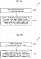
- the method 10 for producing a lithium ion battery includes application of a suitable formation cycle to prepare a lithium ion battery having at least one unit cell as depicted at reference numeral 20.
- the battery formation cycle can have any suitable steps to produce a unit cell having a metal-based anode, a cathode, a separator and electrolyte in operative orientation to one another.
- the metal-based anode employed can be one composed of a metal alloy, more particularly a copper based metal alloy including copper and at least one element alloyed with copper.
- a metal alloy more particularly a copper based metal alloy including copper and at least one element alloyed with copper.
- materials that alloy with copper to produce the metal based anode in the unit cell include at least one of tin, molybdenum, niobium, tungsten, tantalum, and iron. Such alloy materials can be present in the alloy in suitable ratios based on cell requirements.
- the metal alloy can also include alloying particles.
- the alloying particles can be silicon-based, germanium-based or tin-based, for example.
- the silicon-based particles can be silicon, a silicon alloy, a silicon/germanium composite, silicon oxide and combinations thereof.
- the tin-based particles can be tin, tin oxide, a tin alloy and combinations thereof.
- the alloying particles therefore preferably contain at least one element selected from the group consisting of silicon, germanium, tin, silicon oxide, germanium oxide, and a mixture thereof.
- Other high energy density materials known to those skilled in the art are also contemplated. As discussed above, this high capacity for lithium ions results in large volume expansions of the alloying particles.
- the metal-based anode can have an active material coating such as graphite and the like on the metal alloy structure.
- a metal alloy based material can be in overlying relationship to a current collector and can function as an active material in the unit cell. It is also contemplated that an electroactive material such as graphite can be deposited on the alloy material.
- the current collector composition and thickness can vary based on cell requirements.
- the current collector can be a metal foil material such as copper.
- a cathode active material included in the cathode is not particularly limited, and may be a lithium-based composition selected as appropriate.
- cathode active materials include LiCoO 2 , LiNi 0.8 Al 0.05 Co 0.15 O 2 , LiN 1/3 Mn 1/3 Co 1/3 O 2 , LiMn 2 O 4 , and LiFePO 4 .
- the separator is not particularly limited, and may be a polyolefin film having fine pores in a range between 0.01 ⁇ m and 0.1 ⁇ m and a thickness in a range between 10 ⁇ m and 30 ⁇ m.
- the electrolyte is not particularly limited, and may be an electrolyte solution in which lithium salt is dissolved in an organic solvent, a polymer electrolyte in which a polymer such as polyethylene oxide is combined with lithium salt, an inorganic solid electrolyte in which lithium ions move in glass or a crystalline solid, or an ion liquid in which lithium salt is dissolved.
- the various structures present in the unit cell can have such thicknesses and configurations as dictated by battery conditions and performance requirements.
- the electrolyte composition and additive as well as the porosity of the active material can vary based on unit cell requirements.
- the lithium ion battery preparation method as disclosed will include the step of applying a C-rate discharging current to the prepared unit cell as at reference numeral 30.
- the value of the C-rate discharging current that is employed is one that activates the alloying particles at an activation speed (A S ) such that the activation speed during discharge is greater than the rate at which the alloying particles contract upon delithiation during discharge, referred to as the contraction rate (R C ).
- the application of the specified C-rate discharging current results in an anode exhibiting decreases in fracture or pulverized active material, decreases in capacity fade due to collapsed conductive pathways, and reduction in increased internal resistance over time. Without being bound to any theory, it is believed that application of C-rate discharging current at defined value (C D ) will result in delithiation while maintaining the alloying particles in an expanded volume.
- the method includes the step of applying a suitable formation cycle to prepare the unit cell as depicted at reference numeral 20 followed by application of high C-rate discharging current (C HD ).
- high C-rate discharging current (C HD ) is defined as a value greater than the value of the C-rate operating current (C O ) passing through the anode during normal use of the lithium ion battery.
- the high C-rate discharging current (C HD ) may have a range between 3C and 7C in certain applications.
- the C-rate discharging current (C D ) such as the high C-rate discharging current (C HD ) can reduce the state of charge (SOC) in the associated unit cell to a target depleted level.
- the C-rate discharging current (C D ) can be applied for a time interval suitable to secure electronic conductive pathways in a least one structure present in the anode such as the alloy material overlying the current collector.
- conductive pathways can be secured by application of C-rate discharging current (C D ) and/or high C-rate discharging current (C HD ) for an interval sufficient to reduce SOC to a level of 10% maximum charge.
- SOC will be reduced to a level less than 5% of maximum charge.
- the SOC will be reduced to 0% of maximum charge.
- the total discharge interval can vary based on factors such as the particular capacity of the associated cell and/or the C-rate value employed.
- the method for forming a lithium ion battery includes the step of applying formation cycle to prepare the unit cell as at reference numeral 20'.
- a discharging current (C D ) is applied to the unit cell such that alloying particles are activated at an activation speed (As) that is greater than the contraction rate (R C ) of alloying particles.
- Application of the discharging current (C D ) is discontinued when the unit cell reaches a state of charge (SOC) less than 5% of maximum charge as at reference numeral 40'.
- the unit cell After the unit cell has reached the lower state of charge value, the unit cell is charged to 100% SOC by application of charging current (C C ) as at reference numeral 50'.
- the charging current (C C ) can have a C-rate value that is less than the C-rate value of the discharging current (C D ) previously applied.
- suitable C-rate values for the charging current (C C ) include C-rates between 3C and 6C and C-rates between C/20 and 1C.
- Charging current C-rates between 3C and 6C can be employed following high C-rate discharging current (C HD ) application. It is contemplated that either high C-rate charging current or charging current in ranges such as between C/20 and 1C can be employed in other instances.
- the high C-rate charging current (Cc) may be a value greater than the C-rate operating current (Co) passing through the anode during the use of the lithium ion battery.
- the process proceeds with the application of high C-rate discharging current (C HD ) having a value that is greater than the C-rate operating current (C O ) as at reference numeral 32'.
- Application of the high C-rate discharging current (C HD ) is discontinued when the unit cell reaches a state of charge (SOC) less than 5% of maximum charge as at reference numeral 40'.
- SOC state of charge
- the unit cell is charged to 1 00% SOC by application of charging current (C C ).
- the charging current (C C ) will have a C-rate value that is less than the C-rate value of the high discharging current (C HD ) as at reference numeral 50'.
- the charging current will have a C-rate that is between C/20 and 1C.
- the C-rate of the discharging current (C HD ) can be a steady value in the range defined (i.e. 3C to 7C) or can vary within the range defined.
- the interval for application of charging current can vary based on the capacity of the particular unit cell and/or the C-rate employed.
- the present disclosure also contemplates methods for preparing a lithium ion battery that includes at least two discharge/charge iterations.
- One non-limiting example of such a method is outlined in Fig. 3 .
- the unit cell can be prepared by the application of a suitable formation cycle as at reference numeral 20".
- the prepared unit cell can then be subjected to application of a high C-rate discharging current (C D1 ) at a C-rate between 3C and 7C as illustrated at reference numeral 30".
- Application of high C-rate discharging current (C D1 ) can continue for an interval sufficient to reduce the state of charge (SOC) in the unit cell to a lowered state of charge value which is defined as SOC less than 5% of maximum. In many situations, the lowered state of charge value will be an SOC at or near 0% of maximum.
- the application of charging current (C C ) can be applied to the unit cdl as at reference numeral 50". This can occur at rate values between C/20 and 1C and proceeds for an interval sufficient to provide the unit cell with an elevated state of charge. In certain embodiments, it is contemplated that rate values between 3C and 6C can be employed during the charging step.
- the high C-rate charging current (C C ) may be greater than the C-rate operating current (C O ) passing through the anode during the use of the lithium ion battery.
- the elevated state of charge may be any value that is above the previously lowered stated of charge value previously achieved.
- the elevated state of charge achieved in this process step will be at or above 90% of maximum SOC for the unit cell; while in other embodiments, the elevated state of charge will be a value at or near 100% maximum SOC for the unit cell.
- the interval for application of the charging current (C C ) is dependent on factors such as the C-rate value of the charging current (C C ) applied, the capacity and/or configuration of the specific unit cell, or both.
- the application of charging current (C C ) can be discontinued and a high C-rate discharging current (C D2 ) applied as at reference numeral 60" of Fig. 3 .
- the high C-rate discharging current (C D2 ) will have a value that is reduced or decremented from high C-rate discharging current (C D1 ) previously employed.
- the high C-rate discharging current (C D2 ) can be between 0.25C and 2C less than the high C-rate discharging current (C D1 ) previously applied to the unit cell.
- the initial high C-rate discharging current (C D1 ) is 7C
- the immediately subsequent high C-rate discharging current (C D2 ) may have a value of 6C.
- the decremented high C-rate discharging current (C D2 ) will be applied until the SOC in the unit cell is reduced to a state of charge at or less than the lowered state of charge previously achieved. Once the second lowered state of charge has been reached, application of the decremented high C-rate discharging current (C D2 ) is discontinued as depicted in Fig. 3 at reference numeral 70". The interval necessary to achieve the second lowered state of charge is dependent on factors such as the capacity and/or configuration of the specific unit cell, the C-rate of the discharging current (C D2 ), etc.
- the unit cell can be charged to an elevated state of charge as at reference numeral 80".
- This can occur by application of a charging current (C C ) having a C-rate value.
- the C-rate value of the charging current can be between C/20 and 1C; in other applications it is contemplated that the C-rate value of the charging current can be between 3C and 7C.
- the elevated state of charge achieved can be at or above 90% of the maximum SOC; while in other embodiments, the elevated state of charge will be a value at or near 100% of the maximum SOC.
- the interval for application of the charging current (C C ) can vary based on factors such as the C-rate value of the charging current (C C ), the capacity and/or configuration of the specific unit cell, or both.
- the charging current (C C ) applied in this subsequent charging step can have the same value as that applied previously or can differ from that charging current initially applied.
- the charging steps and discharging steps can be repeated through multiple iterations sequentially reducing the high C-rate discharging current with each iteration until the high C-rate discharging current applied has a defined lower value.
- the defined lower value is greater than 0.1C. This is depicted at reference numeral 90" in Fig. 3 .
- the final discharging current value that is applied will be approximately 3C.
- the sequential reductions in discharging current can be in any suitable decreasing sequence; non-limiting examples include equal value intervals, logarithmic intervals, inverse logarithmic intervals and the like.
- One example of a decreasing discharge sequence would be discharge proceeding for one cycle each at 7C, 5C, 3C, 1C, 0.1C.
- the method disclosed can also include multiple charging step iterations in the values previously noted.
- the multiple charging step iterations can be incremented as desired or required.
- the charging step iterations can progress from lowest to highest in increments similar to the increments employed in the high C-rate discharge steps.
- the lithium ion battery that may be produced by the method as disclosed may be one that includes a unit cell having a metal-based anode having a current collector, and an active material structure formed of a suitable metal alloy and an electroactive material coating the surface of the metal alloy structure.
- the resulting anode is characterized by at least one area defined as a spongy region having a conductive network of a suitable metal with alloying particles present within the network defined charge conduit extending through the active material layer to the current collector.
- the representative anode 102 is composed of a metal alloy-based region 104 comprising a metal material such as copper and at least one alloying particle material capable of alloying with the metal material.
- Suitable alloying particle material can be materials that, under suitable circumstances, react with lithium ions in a reversible reaction to produce lithiated complexes in the metal material.
- Non-limiting examples of such materials include materials that alloys with copper such as tin, silicon, germanium, molybdenum, niobium, tungsten, tantalum, iron.
- the metal alloy material is in overlying relationship to a current collector 106.
- the metal alloy-based region 104 has an outer surface 108 opposed to the current collector 106.
- the outer surface 108 is in contact with an active material layer 110.
- the active material layer 110 can be composed of electroconductive materials such as graphite. It is contemplated that the electroconductive material as well as the alloy material will be configured to permit migration and reversible intercalation of lithium ions during charge and discharge cycles.
- the active material layer 110 as well as the metal alloy based region 104 is marked by areas of visible delamination such as areas 112 as well as fissures 114 and/or shafts 116 that extend into the body 118 of the metal alloy based region 104.
- the fissures 114 and/or shafts 116 may extend through to the current collector 106 or may terminate at a location in the body 118 of the metal alloy-based region 104 and/or the active material layer 110.
- the delamination areas 112, fissures 114 and/or shafts 116 can interrupt charge pathways 120 defined in the metal alloy-based region 104.
- the anode 202 is composed of a metal alloy-based region 204 comprising a metal material such as copper and at least one metal that alloys with copper such as tin, silicon, germanium, molybdenum, niobium, tungsten, tantalum, iron in overlying relationship to a current collector 206.
- the material in the metal alloy based-region 204 can be suitably porous in order to accommodate reversible migration of lithium ions.
- the metal alloy-based region 204 has an outer surface 208 in contact with the active material layer 210.
- the active material layer can be composed of a suitable electroactive material such as graphite, graphene or the like.
- the metal alloy-based region 204 can accommodate a plurality of defined electronically conductive pathways 218 that extend uninterrupted from the active material layer 210 located on the outer surface 208 of the metal alloy-based region 204 to the current collector 206.
- the metal alloy-based region 204 is an essentially continuous body having a plurality of pores such as surface pores 220 defined on the surface of the metal alloy-based region 204 and in its interior.
- the lithium ion battery that incorporates anode 202 exhibits stable discharge capacity retention over five plus cycles.
- Figs. 8 and 9 provide a detail diagram of the structure of anodes and the effect of operation of the associated battery with and without the treatment method disclosed herein.
- a detail view of a respective region of anode 102 in the manufactured state is depicted in Fig. 8A .
- the outwardly oriented surface 108 of metal based alloy layer 104 is configured with geometric depictions 150 which are non-limiting conceptual representations of the spongy structure of the associated material.
- a active material layer 110 such as graphite overlays the surface 108 of the metal-based alloy layer 104.
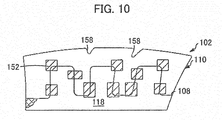
- the metal-based alloy layer 104 includes alloying particles 152 that are dispersed within the metal matrix.
- the alloying particles 152 can be a material that expands upon lithiation.
- Non-limiting examples of such materials include one or more of silicon-based materials such as silicon and silicon oxide and combinations thereof, tin-based material such as tin and tin oxide and combinations thereof, and/or germanium-based materials such as germanium, germanium oxide, oxide with silicon and mixtures thereof.
- FIG. 8B A representation of anode 102 after initial charging is depicted in Fig. 8B .
- the alloying particles experience volume expansion as the particle material reacts to for a lithiated particle complex.
- the lithiated particle complex 152 can expand and displace into the body 118 of the active material layer 110. Particle expansion may also occur with displacement into the metal-based alloy layer 104. Expansion may result in lithiated particle complexes abutting one another as illustrated in Fig 8A .
- Volume expansion in the lithiated particle complexes 152 can result in limited delamination regions 154 as well as localized cracking in the metal-based alloy material as at reference numeral 156. Some minor amounts of surface cracking can also be evidences as at reference numeral 158.
- FIG. 9 A representative illustration of the anode 102 after initial slow discharge is depicted in Fig. 9 .
- Slow discharge of the anode results in shrinkage of the alloying particles 152 back to their pre-charge volume as delithiation occurs. This produces voids 160 that are defined primarily in the active material layer 110.
- Shrinkage of alloying particles causes propagations of surface cracks 158 initiated during the charging interval and can produce new surface cracks such as crack 160.
- cracks 156 located in the metal-based alloy layer 104 can be propagated. In certain instances, new cracks 162 can be initiated in either the metal-based alloy layer 104 or the active material layer.
- Delamination regions 154 initiated during charging can be propagated and new delamination regions can be produced as a result of discharge and associated shrinkage of alloying particle 152. Crack propagation and delamination together with the induced voids result in an anode that exhibits high rate resistance and low rate capability.
- discharge occurs at an activation speed (As) that is greater than the contraction rate (R C ) of the alloying particles such that the volume of the alloying particles subsequent to discharge is at least greater than the volume of the alloying particles in the anode as manufactured.
- As activation speed
- R C contraction rate
- the method for preparing the lithium ion battery according to the present embodiment is a preconditioning process before using the lithium ion battery.
- the method for preparing the lithium ion battery includes the step of, after a unit cell has been formed, the unit cell having a cathode, a separator, an electrolyte, and a metal-based anode, the metal-based anode having alloying particles present therein, applying a high C-rate discharging current to the unit cell.
- the preparation method further includes the step of, after application of the high C-rate discharging current has been discontinued, applying a high C-rate charging current to the unit cell to charge the unit cell to an elevated state of charge which is at or above 90% of maximum state of charge for the unit cell.
- the high C-rate discharging current (C HD ) is sufficient to secure conductive pathways in at least one structure present in the unit cell.
- the high C-rate discharging current (C HD ) applied is greater than a C-rate operating current (C O ) passing through the metal-based anode during use of the lithium ion battery.
- the high C-rate charging current has a value greater than the C-rate operating current (C O ) passing through the metal-based anode during use of the lithium ion battery.
- the high C-rate discharging current applied to the anode (C HD ) is preferably in a range between 3C and 7C.
- the high C-rate discharging current applied preferably results in delithiation of alloying particles producing porous alloying particles.
- the high C-rate discharging current applied preferably has a variable value in a range between 3C and 7C for at least one interval during the high C-rate discharging current application step.
- the high C-rate discharging current applied preferably varies decrementally between 7C and 3C during the high C-rate discharging current application step.
- the method for preparing the lithium ion battery further includes the step of discontinuing the high C-rate discharging current application step when the unit cell reaches a reduced state of charge, wherein the reduced state of charge preferably has a value less than 5% of maximum charge of the unit cell.
- the method for preparing the lithium ion battery further includes the step of discontinuing the high C-rate discharging current application step when the unit cell reaches a reduced state of charge, wherein the reduced state of charge preferably has a value of 0% of maximum charge of the unit cell.
- the method for preparing the lithium ion battery preferably consists of one discharging current application step and one charging step.
- the method for preparing the lithium ion battery according to the present embodiment is a preconditioning process before using the lithium ion battery.
- the method for preparing the lithium ion battery includes the step of, after a unit cell has been formed, the unit cell having a cathode, a separator, an electrolyte, and a metal-based anode, the metal-based anode having alloying particles present therein, applying a discharging current to the unit cell to trigger initial delithiation of the alloying particles.
- the preparation method further includes the step of, after discontinuation of the application of the discharging current, applying a high C-rate charging current having a value between 3C and 6C to the unit cell.
- the metal-based anode has the alloying particles exhibiting an expansion rate (R E ) upon lithiation and a contraction rate (R C ) upon initial delithiation, the alloying particles having an initial volume and an expanded volume subsequent to initial charging.
- Application of the discharging current activates the alloying particles at an activation speed (A S ), and the activation speed (A S ) is greater than the contraction rate (R C ) of the alloying particles.
- the discharging current applied has a C-rate between 3C and 7C which is a first incremental value.
- the preparation method further includes the steps of discontinuing the discharging current application step when the unit cell reaches a reduced state of charge having a value of 0% of maximum charge of the unit cell, and charging the unit cell to a value equal to an elevated state of charge having 100% of a state of charge after the discharge current application step has been discontinued.
- the preparation method further includes the step of, after the unit cell has achieved the elevated state of charge, applying a high C-rate discharging current to the unit cell, the high C-rate discharging current having a second incremental value less than the first incremental value.
- the preparation method further includes the steps of discontinuing the high C-rate discharging current application step when the unit cell reaches a reduced state of charge, the reduced state of charge having a value of 0% of maximum charge of the unit cell, and charging the unit cell to the elevated state of charge after the high C-rate discharging current application has been discontinued.
- the second incremental value is preferably at least 0.25C lower than the first incremental value.
- the method for preparing the lithium ion battery according to the present embodiment is a method of improving battery life in the lithium ion battery having at least one copper metal based alloy anode.
- the method for preparing the lithium ion battery includes the step of forming a lithium ion battery having at least one unit cell, the at least one unit cell having a cathode, a separator, an electrolyte, and the metal-based anode including copper.
- the metal-based anode has alloying particles, the alloying particles has an initial volume and an expanded volume subsequent to initial charging, the alloying particles exhibiting an expansion rate (R E ) upon lithiation and a contraction rate (R C ) upon initial delithiation upon discharge.
- the lithium ion battery obtained in the forming step has an initial elevated state of charge.
- the method for preparing the lithium ion battery further includes the step of preconditioning the lithium ion battery, the preconditioning step including applying a high C-rate discharging current to the unit cell, and recharging the unit cell at a C-rate between 3C and 6C to an elevated state of charge.
- Application of the high C-rate discharging current activates the alloying particles at an activation speed (A S ).
- the activation speed (A S ) is greater than the contraction rate (R C ) of the alloying particles for an interval and in an amount sufficient to reduce the initial elevated state of charge to a reduced state of charge, and the high C-rate discharging current is between 3C and 7C.
- the elevated state of charge has a value level equivalent to 100% of a state of charge.
- the phrase "initial elevated state of charge” refers to a charging level of the lithium ion battery obtained in the forming step before the preconditioning step.
- the high C-rate discharging current has a value sufficient to secure electronic conductive pathways in at least one structure present in the unit cell.
- the high C-rate discharging current applied results in delithiation of alloying particles and produces porous structure therein having a particle volume after discharge that is greater than the initial volume.
- the high C-rate discharge current application step and recharging step are preferably repeated sequentially, and the high C-rate discharging current is preferably 7C in the initial applying step and is reduced by between 0.25C and 1C with each sequential iteration.
- a lithium ion battery is prepared applying a standard formation cycle to unit cells.
- a rate capability check is performed in sequential order from 0.1C to 5C rate on the resulting unit cell.
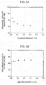
- the rate capabilities are illustrated in Fig. 6A .
- the anode exhibits a monotonous decrease in performance with increasing C-rate. Scanning electromicrographic analysis performed at 100X indicate multiple areas of delamination as depicted in Fig. 7A .
- a lithium ion battery is prepared applying the standard formation cycle to unit cells as outlined in Comparative Example 1.
- a high C-rate discharging current having a value of 7C is applied to the unit cell for an interval sufficient to produce a state of charge in the unit cell of 0%.
- the unit cell is charged back to 100% state of charge by application of a charging C-rate of 1C for and interval sufficient to achieve 100% SOC.
- a rate capability check is performed on the resulting cell in sequential order from 5C to 0.1C a intervals of 5C, 3C, 2C, 1C, 0.5C and 0.1C.
- the rate capabilities are illustrated in Fig. 6B .
- the anode exhibits a stable dependence of discharge capacity retention percentage as a function of C-rate.
- a lithium ion battery is prepared applying the standard formation cycle to unit cells as outlined in Comparative Example 1.
- a high C-rate discharging current having a value of 3C is applied to the unit cell for an interval sufficient to produce a state of charge in the unit cell of 0%.
- the unit cell is charged back to 100% state of charge by application of a charging C-rate of C/20 for and interval sufficient to achieve 100% SOC.
- a rate capability check is performed on the resulting unit cell in sequential order from 5C to 0.1C rate indicates that unit cell performance is similar to that demonstrated in Example 1.
- a lithium ion battery is prepared applying the standard formation cycle to unit cells as outlined in Comparative Example 1.
- An initial high C-rate discharging current having a value of 7C is applied to the unit cell for an interval sufficient to produce a state of charge in the unit cell of 0%.
- the unit cell is charged back to 100% state of charge by application of a charging C-rate of 1C for and interval sufficient to achieve 100% SOC.
- the unit cell is then subjected to application of a discharging current having a value of 5C followed by application of a charging C-rate of 1C.
- Discharging and charging steps are repeated over several cycles using discharge rates of 3 C; 1 C and 0.1 C respectively.
- a rate capability check performed on the unit cell in sequential order from 5C to 0.1C respectively indicates that unit cell performance is similar to that demonstrated in Example 1.
Landscapes
- Chemical & Material Sciences (AREA)
- Engineering & Computer Science (AREA)
- Chemical Kinetics & Catalysis (AREA)
- Electrochemistry (AREA)
- General Chemical & Material Sciences (AREA)
- Manufacturing & Machinery (AREA)
- Materials Engineering (AREA)
- Battery Electrode And Active Subsutance (AREA)
- Secondary Cells (AREA)
Abstract
Description
- This disclosure relates to lithium ion batteries and methods for making the same, and in particular to methods for improving low temperature lithium ion battery performance and lithium ion batteries with improved rate capacity profiles.
- Hybrid vehicle (HEV) and electric vehicles (EV) use chargeable-dischargeable power sources. Secondary batteries such as lithium-ion batteries are typical power sources for HEV and EV. Certain types of lithium-ion secondary batteries use conductive metal and metal-based alloy material as the anode electrode. Lithium ion batteries having metal or metal alloy anodes suffer rapid capacity fade, poor cycle life and poor durability and exhibit lower discharge retention rates at elevated C-rates as well as irregular dependence of discharge capacity retention percentage as a function of C-rate. One cause of the decrease in discharge capacity retention percentage is due to damage in the electrode microstructure caused by multiple battery cycling evidenced the development of delamination sites and large cracking networks propagating in the structure. This deteriorative phenomenon leads to electrode delamination, loss of porosity, electrical isolation of the active material, rapid capacity fade and ultimate cell failure.
- Patent Literature 1 discloses a method for preparing a lithium ion secondary battery having high low-temperature pulse discharging performance and low-temperature charging performance, promoted safety upon overcharge, and high heat resistivity. Patent Literature 1 discloses that the lithium ion secondary battery including a cathode, an anode, a separator, and a non-aqueous electrolyte solution is subjected to heat treatment at high temperature during being charged, and then subjected to charge-discharge treatment including at least one high-load constant-current discharge treatment of 1.5 C or higher.
- Patent Literature 1: Japanese Patent Unexamined Publication No.
2004-030939 - A method for preparing a lithium ion battery having at least one unit cell in which the unit cell has a cathode, a separator, an electrolyte and a metal based anode that includes a metal based alloy overlaying a metal current collector. The metal based alloy has alloying particles present therein. The method includes the step of applying a high C-rate discharging current to the unit cell, the high C-rate discharging current (CHD) sufficient to secure conductive pathways in at least one structure present in the unit cell, wherein the high C-rate discharging current (CHD) applied is greater than a C-rate operating current (CO) passing through the metal-based anode during use and the step of charging the unit cell with the application of a high C-rate charging current after the application of the discharging current has been discontinued.
- These and other aspects of the present disclosure are disclosed in the following detailed description of the embodiments, the appended claims and the accompanying figures.
- The invention is best understood from the following detailed description when read in conjunction with the accompanying drawings. It is emphasized that, according to common practice, the various features of the drawings are not to-scale. On the contrary, the dimensions of the various features are arbitrarily expanded or reduced for clarity. Included in the drawings are the following figures:
-
- [
Fig. 1A] Fig. 1A is flow chart depicting a method for preparing a lithium ion battery according to embodiments as disclosed herein. - [
Fig. 1B] Fig. 1B is flow chart depicting a method for preparing a lithium ion battery according to embodiments as disclosed herein. - [
Fig. 2A] Fig. 2A is flow chart depicting alternate embodiments of the method for preparing a lithium ion battery as disclosed herein. - [
Fig. 2B] Fig. 2B is flow chart depicting alternate embodiments of the method for preparing a lithium ion battery as disclosed herein. - [
Fig. 3] Fig. 3 is a flow chart depicting a second alternate embodiment of a method for preparing a lithium ion battery as disclosed herein. - [
Fig. 4] Fig 4 is a cross-sectional view of a region of a metal alloy anode and associated structure of a representative unit cell of lithium ion battery according to the prior art. - [
Fig. 5] Fig. 5 is a cross-sectional view of a region of a metal alloy anode and associated structure of a unit cell of a lithium ion battery produced according to an embodiment as disclosed herein. - [
Fig. 6A] Fig. 6A is graphic depiction of discharge capacity retention vs delithiation rate for a lithium ion battery ofFig. 4 . - [
Fig. 6B] Fig. 6B is graphic depiction of discharge capacity retention vs delithiation rate for a lithium ion battery ofFig. 5 . - [
Fig. 7A] Fig. 7A is scanning electromicrographic view of the top of the anode ofFig. 4 . - [
Fig. 7B] Fig. 7B is scanning electromicrographic view of the top of anode ofFig. 5 . - [
Fig. 8A] Fig. 8A is detail view of a conceptual schematic of an embodiment of the alloy structure of an electrode as disclosed herein after formation. - [
Fig. 8B] Fig. 8B is detail view of a conceptual schematic of an embodiment of the alloy structure of an electrode as disclosed herein after lithiation upon initial charging. - [
Fig. 9] Fig. 9 is a detail view of the electrode detail ofFig. 8B after a slow discharge step. - [
Fig. 10] Fig. 10 is detail view of the electrode detail ofFig. 8B after application of high current discharge according to an embodiment of the method disclosed herein. - Lithium ion batteries using metal-based alloy anodes suffer from poor rate capability. This poor rate capability limits the applications for such batteries. Based on rate capability analysis, it has been found that batteries having metal-based alloy anodes exhibit a monotonous decrease in performance as C-rate increases. It is believed that this phenomenon is due, at least in part to the compromise in electronic conductive pathways defined through the anode structure to the current collector which become compromised due to one or more of cracking and delamination of the active material, solid electrolyte interface (SEI) layer overgrowth due to side reactions, electrolyte decomposition. Each of these, in turn, can lead to increases in resistance. Impairment of the electronic conductive pathway can cause lithium ion diffusion to become blocked or impaired.
- To address the poor energy density of carbon based electrodes, alternative active materials with higher energy densities are desired. Alloying particles such as silicon, tin, germanium and their oxides and alloys are non-limiting examples of materials that may be added to an electrode active material layer to improve its energy density, among other benefits. In certain applications, electrodes can be constructed that have regions of carbon-based material such as graphite as well as regions containing alloying particles.
- Electrode materials such as silicon, germanium, or tin react with lithium via a mechanism different from that of graphite. Lithium forms alloys with electrode material such as silicon in a process that involves breaking the bonds between host atoms, causing dramatic structure changes in the process. Since alloying materials such as silicon, germanium, or tin do not constrain the reaction, anode materials that form alloys can have much higher specific capacity than intercalation electrode materials such as graphite. Anode-active materials such as silicon, germanium, tin and the like suffer from rapid capacity fade, poor cycle life and poor durability. One primary cause of this rapid capacity fade is the massive volume expansion of these materials (typically up to 300%) and structural changes due to lithium insertion. Repeated volume expansion of materials such as silicon can cause particle cracking and pulverization when the silicon has no room to expand, which leads to delamination of the active material layer from the current collector, electrical isolation of the fractured or pulverized active material, capacity fade due to collapsed conductive pathways, and increased internal resistance over time.
- The present disclosure is predicated on the unexpected discovery that assembly and treatment processes such as those disclosed can produce metal alloy anodes and associated lithium ion batteries that exhibit a stable, flat dependence of discharge capacity retention as a function of C-rate.
- As depicted in
Fig, 1A , themethod 10 for producing a lithium ion battery includes application of a suitable formation cycle to prepare a lithium ion battery having at least one unit cell as depicted atreference numeral 20. The battery formation cycle can have any suitable steps to produce a unit cell having a metal-based anode, a cathode, a separator and electrolyte in operative orientation to one another. - The metal-based anode employed can be one composed of a metal alloy, more particularly a copper based metal alloy including copper and at least one element alloyed with copper. Non-limiting examples of materials that alloy with copper to produce the metal based anode in the unit cell include at least one of tin, molybdenum, niobium, tungsten, tantalum, and iron. Such alloy materials can be present in the alloy in suitable ratios based on cell requirements. The metal alloy can also include alloying particles. The alloying particles can be silicon-based, germanium-based or tin-based, for example. The silicon-based particles can be silicon, a silicon alloy, a silicon/germanium composite, silicon oxide and combinations thereof. The tin-based particles can be tin, tin oxide, a tin alloy and combinations thereof. The alloying particles therefore preferably contain at least one element selected from the group consisting of silicon, germanium, tin, silicon oxide, germanium oxide, and a mixture thereof. Other high energy density materials known to those skilled in the art are also contemplated. As discussed above, this high capacity for lithium ions results in large volume expansions of the alloying particles.
- Where desired, the metal-based anode can have an active material coating such as graphite and the like on the metal alloy structure. In the anode as disclosed, a metal alloy based material can be in overlying relationship to a current collector and can function as an active material in the unit cell. It is also contemplated that an electroactive material such as graphite can be deposited on the alloy material. The current collector composition and thickness can vary based on cell requirements. In certain embodiments, the current collector can be a metal foil material such as copper.
- A cathode active material included in the cathode is not particularly limited, and may be a lithium-based composition selected as appropriate. Examples of cathode active materials include LiCoO2, LiNi0.8Al0.05Co0.15O2, LiN1/3Mn1/3Co1/3O2, LiMn2O4, and LiFePO4. The separator is not particularly limited, and may be a polyolefin film having fine pores in a range between 0.01 µm and 0.1 µm and a thickness in a range between 10 µm and 30 µm. The electrolyte is not particularly limited, and may be an electrolyte solution in which lithium salt is dissolved in an organic solvent, a polymer electrolyte in which a polymer such as polyethylene oxide is combined with lithium salt, an inorganic solid electrolyte in which lithium ions move in glass or a crystalline solid, or an ion liquid in which lithium salt is dissolved.
- The various structures present in the unit cell can have such thicknesses and configurations as dictated by battery conditions and performance requirements. The electrolyte composition and additive as well as the porosity of the active material can vary based on unit cell requirements.
- The lithium ion battery preparation method as disclosed will include the step of applying a C-rate discharging current to the prepared unit cell as at
reference numeral 30. The value of the C-rate discharging current that is employed is one that activates the alloying particles at an activation speed (AS) such that the activation speed during discharge is greater than the rate at which the alloying particles contract upon delithiation during discharge, referred to as the contraction rate (RC). The application of the specified C-rate discharging current results in an anode exhibiting decreases in fracture or pulverized active material, decreases in capacity fade due to collapsed conductive pathways, and reduction in increased internal resistance over time. Without being bound to any theory, it is believed that application of C-rate discharging current at defined value (CD) will result in delithiation while maintaining the alloying particles in an expanded volume. - In certain embodiments such as the method as depicted in Fig. IB, the method includes the step of applying a suitable formation cycle to prepare the unit cell as depicted at
reference numeral 20 followed by application of high C-rate discharging current (CHD). As used herein, high C-rate discharging current (CHD) is defined as a value greater than the value of the C-rate operating current (CO) passing through the anode during normal use of the lithium ion battery. The high C-rate discharging current (CHD) may have a range between 3C and 7C in certain applications. - The C-rate discharging current (CD) such as the high C-rate discharging current (CHD) can reduce the state of charge (SOC) in the associated unit cell to a target depleted level. The C-rate discharging current (CD) can be applied for a time interval suitable to secure electronic conductive pathways in a least one structure present in the anode such as the alloy material overlying the current collector. In certain embodiments, it is believed that conductive pathways can be secured by application of C-rate discharging current (CD) and/or high C-rate discharging current (CHD) for an interval sufficient to reduce SOC to a level of 10% maximum charge. In certain instances, SOC will be reduced to a level less than 5% of maximum charge. In many instances, the SOC will be reduced to 0% of maximum charge. It is understood that the total discharge interval can vary based on factors such as the particular capacity of the associated cell and/or the C-rate value employed.
- In the method 10' depicted in the flow chart in
Fig. 2A , the method for forming a lithium ion battery includes the step of applying formation cycle to prepare the unit cell as at reference numeral 20'. After the formation step is completed, a discharging current (CD) is applied to the unit cell such that alloying particles are activated at an activation speed (As) that is greater than the contraction rate (RC) of alloying particles. Application of the discharging current (CD) is discontinued when the unit cell reaches a state of charge (SOC) less than 5% of maximum charge as at reference numeral 40'. After the unit cell has reached the lower state of charge value, the unit cell is charged to 100% SOC by application of charging current (CC) as at reference numeral 50'. In certain applications, the charging current (CC) can have a C-rate value that is less than the C-rate value of the discharging current (CD) previously applied. Non-limiting examples of suitable C-rate values for the charging current (CC) include C-rates between 3C and 6C and C-rates between C/20 and 1C. Charging current C-rates between 3C and 6C can be employed following high C-rate discharging current (CHD) application. It is contemplated that either high C-rate charging current or charging current in ranges such as between C/20 and 1C can be employed in other instances. The high C-rate charging current (Cc) may be a value greater than the C-rate operating current (Co) passing through the anode during the use of the lithium ion battery. - In the method 10' as depicted in
Fig. 2B , the process proceeds with the application of high C-rate discharging current (CHD) having a value that is greater than the C-rate operating current (CO) as at reference numeral 32'. Application of the high C-rate discharging current (CHD) is discontinued when the unit cell reaches a state of charge (SOC) less than 5% of maximum charge as at reference numeral 40'. After the unit cell has reached the lower state of charge value, the unit cell is charged to 1 00% SOC by application of charging current (CC). The charging current (CC) will have a C-rate value that is less than the C-rate value of the high discharging current (CHD) as at reference numeral 50'. In certain embodiments the charging current will have a C-rate that is between C/20 and 1C. The C-rate of the discharging current (CHD) can be a steady value in the range defined (i.e. 3C to 7C) or can vary within the range defined. The interval for application of charging current can vary based on the capacity of the particular unit cell and/or the C-rate employed. - It has been found that one cycle of C-rate discharge current application at the defined rates followed by charging to 100% SOC administered prior to operation of the associated battery provides a lithium ion battery that demonstrates improved discharge capacity retention during cycling over that which occurs in routine battery operation of similarly structured battery units.
- The present disclosure also contemplates methods for preparing a lithium ion battery that includes at least two discharge/charge iterations. One non-limiting example of such a method is outlined in
Fig. 3 . The unit cell can be prepared by the application of a suitable formation cycle as atreference numeral 20". The prepared unit cell can then be subjected to application of a high C-rate discharging current (CD1) at a C-rate between 3C and 7C as illustrated atreference numeral 30". Application of high C-rate discharging current (CD1) can continue for an interval sufficient to reduce the state of charge (SOC) in the unit cell to a lowered state of charge value which is defined as SOC less than 5% of maximum. In many situations, the lowered state of charge value will be an SOC at or near 0% of maximum. Once the unit cell reaches the lowered state of charge value, application of high C-rate discharging current (CD1) is discontinued as atreference numeral 40". - Once the unit cell reaches the lowered state of charge value and high C-rate discharging current (CD1) is discontinued, the application of charging current (CC) can be applied to the unit cdl as at
reference numeral 50". This can occur at rate values between C/20 and 1C and proceeds for an interval sufficient to provide the unit cell with an elevated state of charge. In certain embodiments, it is contemplated that rate values between 3C and 6C can be employed during the charging step. The high C-rate charging current (CC) may be greater than the C-rate operating current (CO) passing through the anode during the use of the lithium ion battery. The elevated state of charge may be any value that is above the previously lowered stated of charge value previously achieved. In certain embodiments, the elevated state of charge achieved in this process step will be at or above 90% of maximum SOC for the unit cell; while in other embodiments, the elevated state of charge will be a value at or near 100% maximum SOC for the unit cell. The interval for application of the charging current (CC) is dependent on factors such as the C-rate value of the charging current (CC) applied, the capacity and/or configuration of the specific unit cell, or both. - Once the unit cell reaches the elevated state of charge, the application of charging current (CC) can be discontinued and a high C-rate discharging current (CD2) applied as at
reference numeral 60" ofFig. 3 . The high C-rate discharging current (CD2) will have a value that is reduced or decremented from high C-rate discharging current (CD1) previously employed. In certain embodiments, the high C-rate discharging current (CD2) can be between 0.25C and 2C less than the high C-rate discharging current (CD1) previously applied to the unit cell. As a non-limiting example, if the initial high C-rate discharging current (CD1) is 7C, the immediately subsequent high C-rate discharging current (CD2) may have a value of 6C. - The decremented high C-rate discharging current (CD2) will be applied until the SOC in the unit cell is reduced to a state of charge at or less than the lowered state of charge previously achieved. Once the second lowered state of charge has been reached, application of the decremented high C-rate discharging current (CD2) is discontinued as depicted in
Fig. 3 atreference numeral 70". The interval necessary to achieve the second lowered state of charge is dependent on factors such as the capacity and/or configuration of the specific unit cell, the C-rate of the discharging current (CD2), etc. - Once the second lowered state of charge is reached, the unit cell can be charged to an elevated state of charge as at
reference numeral 80". This can occur by application of a charging current (CC) having a C-rate value. In certain applications, the C-rate value of the charging current can be between C/20 and 1C; in other applications it is contemplated that the C-rate value of the charging current can be between 3C and 7C. The elevated state of charge achieved can be at or above 90% of the maximum SOC; while in other embodiments, the elevated state of charge will be a value at or near 100% of the maximum SOC. As with prior charging cycles, the interval for application of the charging current (CC) can vary based on factors such as the C-rate value of the charging current (CC), the capacity and/or configuration of the specific unit cell, or both. The charging current (CC) applied in this subsequent charging step can have the same value as that applied previously or can differ from that charging current initially applied. - The charging steps and discharging steps can be repeated through multiple iterations sequentially reducing the high C-rate discharging current with each iteration until the high C-rate discharging current applied has a defined lower value. The defined lower value is greater than 0.1C. This is depicted at
reference numeral 90" inFig. 3 . In certain embodiments of the method as disclosed, the final discharging current value that is applied will be approximately 3C. - The sequential reductions in discharging current can be in any suitable decreasing sequence; non-limiting examples include equal value intervals, logarithmic intervals, inverse logarithmic intervals and the like. One example of a decreasing discharge sequence would be discharge proceeding for one cycle each at 7C, 5C, 3C, 1C, 0.1C.
- The method disclosed can also include multiple charging step iterations in the values previously noted. The multiple charging step iterations can be incremented as desired or required. In certain embodiments, the charging step iterations can progress from lowest to highest in increments similar to the increments employed in the high C-rate discharge steps.
- The lithium ion battery that may be produced by the method as disclosed may be one that includes a unit cell having a metal-based anode having a current collector, and an active material structure formed of a suitable metal alloy and an electroactive material coating the surface of the metal alloy structure. The resulting anode is characterized by at least one area defined as a spongy region having a conductive network of a suitable metal with alloying particles present within the network defined charge conduit extending through the active material layer to the current collector.
- A schematic cross-sectional depiction of a
representative anode 102 and associatedstructure 100 present in a lithium ion battery prepared according to methods known in the prior art after five plus operative cycles is depicted inFig. 4 . Therepresentative anode 102 is composed of a metal alloy-basedregion 104 comprising a metal material such as copper and at least one alloying particle material capable of alloying with the metal material. Suitable alloying particle material can be materials that, under suitable circumstances, react with lithium ions in a reversible reaction to produce lithiated complexes in the metal material. Non-limiting examples of such materials include materials that alloys with copper such as tin, silicon, germanium, molybdenum, niobium, tungsten, tantalum, iron. In the anode construction, the metal alloy material is in overlying relationship to acurrent collector 106. The metal alloy-basedregion 104 has anouter surface 108 opposed to thecurrent collector 106. Theouter surface 108 is in contact with anactive material layer 110. Theactive material layer 110 can be composed of electroconductive materials such as graphite. It is contemplated that the electroconductive material as well as the alloy material will be configured to permit migration and reversible intercalation of lithium ions during charge and discharge cycles. - As depicted in
Fig, 4 , after at least five charge-discharge cycles, theactive material layer 110 as well as the metal alloy basedregion 104 is marked by areas of visible delamination such asareas 112 as well asfissures 114 and/orshafts 116 that extend into thebody 118 of the metal alloy basedregion 104. Thefissures 114 and/orshafts 116 may extend through to thecurrent collector 106 or may terminate at a location in thebody 118 of the metal alloy-basedregion 104 and/or theactive material layer 110. Thedelamination areas 112,fissures 114 and/orshafts 116 can interruptcharge pathways 120 defined in the metal alloy-basedregion 104. - In contrast, a cross-sectional representation of
anode 202 and associatedstructure 200 produced according the method as disclosed herein after five-plus operative cycles is depicted inFig. 5 . Theanode 202 is composed of a metal alloy-basedregion 204 comprising a metal material such as copper and at least one metal that alloys with copper such as tin, silicon, germanium, molybdenum, niobium, tungsten, tantalum, iron in overlying relationship to acurrent collector 206. The material in the metal alloy based-region 204 can be suitably porous in order to accommodate reversible migration of lithium ions. The metal alloy-basedregion 204 has anouter surface 208 in contact with theactive material layer 210. In various embodiments, the active material layer can be composed of a suitable electroactive material such as graphite, graphene or the like. The metal alloy-basedregion 204 can accommodate a plurality of defined electronicallyconductive pathways 218 that extend uninterrupted from theactive material layer 210 located on theouter surface 208 of the metal alloy-basedregion 204 to thecurrent collector 206. The metal alloy-basedregion 204 is an essentially continuous body having a plurality of pores such as surface pores 220 defined on the surface of the metal alloy-basedregion 204 and in its interior. - The lithium ion battery that incorporates
anode 202 exhibits stable discharge capacity retention over five plus cycles. - To further illustrate the invention as disclosed herein, attention is directed to
Figs. 8 and 9 that provide a detail diagram of the structure of anodes and the effect of operation of the associated battery with and without the treatment method disclosed herein. A detail view of a respective region ofanode 102 in the manufactured state is depicted inFig. 8A . The outwardly orientedsurface 108 of metal basedalloy layer 104 is configured withgeometric depictions 150 which are non-limiting conceptual representations of the spongy structure of the associated material. Aactive material layer 110 such as graphite overlays thesurface 108 of the metal-basedalloy layer 104. The metal-basedalloy layer 104 includes alloyingparticles 152 that are dispersed within the metal matrix. In certain embodiments, the alloyingparticles 152 can be a material that expands upon lithiation. Non-limiting examples of such materials include one or more of silicon-based materials such as silicon and silicon oxide and combinations thereof, tin-based material such as tin and tin oxide and combinations thereof, and/or germanium-based materials such as germanium, germanium oxide, oxide with silicon and mixtures thereof. - A representation of
anode 102 after initial charging is depicted inFig. 8B . Upon charging, the alloying particles experience volume expansion as the particle material reacts to for a lithiated particle complex. Thelithiated particle complex 152 can expand and displace into thebody 118 of theactive material layer 110. Particle expansion may also occur with displacement into the metal-basedalloy layer 104. Expansion may result in lithiated particle complexes abutting one another as illustrated inFig 8A . Volume expansion in thelithiated particle complexes 152 can result inlimited delamination regions 154 as well as localized cracking in the metal-based alloy material as atreference numeral 156. Some minor amounts of surface cracking can also be evidences as atreference numeral 158. - A representative illustration of the
anode 102 after initial slow discharge is depicted inFig. 9 . Slow discharge of the anode results in shrinkage of the alloyingparticles 152 back to their pre-charge volume as delithiation occurs. This producesvoids 160 that are defined primarily in theactive material layer 110. Shrinkage of alloying particles causes propagations of surface cracks 158 initiated during the charging interval and can produce new surface cracks such ascrack 160. Additionally cracks 156 located in the metal-basedalloy layer 104 can be propagated. In certain instances,new cracks 162 can be initiated in either the metal-basedalloy layer 104 or the active material layer.Delamination regions 154 initiated during charging can be propagated and new delamination regions can be produced as a result of discharge and associated shrinkage of alloyingparticle 152. Crack propagation and delamination together with the induced voids result in an anode that exhibits high rate resistance and low rate capability. - In the method disclosed herein, discharge occurs at an activation speed (As) that is greater than the contraction rate (RC) of the alloying particles such that the volume of the alloying particles subsequent to discharge is at least greater than the volume of the alloying particles in the anode as manufactured. In certain embodiments it is believed that the volume of the alloying particles subsequent to discharge is essentially equal to the volume of the alloying particles upon full lithiation upon charging.
- Without being bound to any theory, it is believed that rapid delithiation from of the lithiated alloying particles maintains the apparent particle size of alloying particles resulting in good electronic conductivity between alloying
particles 152 to thebody 118 and less volume loss of entire active materials layers 104 and 110 including alloyingparticles 152. - As described above, the method for preparing the lithium ion battery according to the present embodiment is a preconditioning process before using the lithium ion battery. The method for preparing the lithium ion battery includes the step of, after a unit cell has been formed, the unit cell having a cathode, a separator, an electrolyte, and a metal-based anode, the metal-based anode having alloying particles present therein, applying a high C-rate discharging current to the unit cell. The preparation method further includes the step of, after application of the high C-rate discharging current has been discontinued, applying a high C-rate charging current to the unit cell to charge the unit cell to an elevated state of charge which is at or above 90% of maximum state of charge for the unit cell. The high C-rate discharging current (CHD) is sufficient to secure conductive pathways in at least one structure present in the unit cell. The high C-rate discharging current (CHD) applied is greater than a C-rate operating current (CO) passing through the metal-based anode during use of the lithium ion battery. The high C-rate charging current has a value greater than the C-rate operating current (CO) passing through the metal-based anode during use of the lithium ion battery.
- The high C-rate discharging current applied to the anode (CHD) is preferably in a range between 3C and 7C. The high C-rate discharging current applied preferably results in delithiation of alloying particles producing porous alloying particles.
- The high C-rate discharging current applied preferably has a variable value in a range between 3C and 7C for at least one interval during the high C-rate discharging current application step.
- The high C-rate discharging current applied preferably varies decrementally between 7C and 3C during the high C-rate discharging current application step.
- The method for preparing the lithium ion battery further includes the step of discontinuing the high C-rate discharging current application step when the unit cell reaches a reduced state of charge, wherein the reduced state of charge preferably has a value less than 5% of maximum charge of the unit cell.
- The method for preparing the lithium ion battery further includes the step of discontinuing the high C-rate discharging current application step when the unit cell reaches a reduced state of charge, wherein the reduced state of charge preferably has a value of 0% of maximum charge of the unit cell.
- The method for preparing the lithium ion battery preferably consists of one discharging current application step and one charging step.
- The method for preparing the lithium ion battery according to the present embodiment is a preconditioning process before using the lithium ion battery. The method for preparing the lithium ion battery includes the step of, after a unit cell has been formed, the unit cell having a cathode, a separator, an electrolyte, and a metal-based anode, the metal-based anode having alloying particles present therein, applying a discharging current to the unit cell to trigger initial delithiation of the alloying particles. The preparation method further includes the step of, after discontinuation of the application of the discharging current, applying a high C-rate charging current having a value between 3C and 6C to the unit cell. The metal-based anode has the alloying particles exhibiting an expansion rate (RE) upon lithiation and a contraction rate (RC) upon initial delithiation, the alloying particles having an initial volume and an expanded volume subsequent to initial charging. Application of the discharging current activates the alloying particles at an activation speed (AS), and the activation speed (AS) is greater than the contraction rate (RC) of the alloying particles.
- The discharging current applied has a C-rate between 3C and 7C which is a first incremental value. The preparation method further includes the steps of discontinuing the discharging current application step when the unit cell reaches a reduced state of charge having a value of 0% of maximum charge of the unit cell, and charging the unit cell to a value equal to an elevated state of charge having 100% of a state of charge after the discharge current application step has been discontinued.
- The preparation method further includes the step of, after the unit cell has achieved the elevated state of charge, applying a high C-rate discharging current to the unit cell, the high C-rate discharging current having a second incremental value less than the first incremental value. The preparation method further includes the steps of discontinuing the high C-rate discharging current application step when the unit cell reaches a reduced state of charge, the reduced state of charge having a value of 0% of maximum charge of the unit cell, and charging the unit cell to the elevated state of charge after the high C-rate discharging current application has been discontinued.
- The second incremental value is preferably at least 0.25C lower than the first incremental value.
- The method for preparing the lithium ion battery according to the present embodiment is a method of improving battery life in the lithium ion battery having at least one copper metal based alloy anode. The method for preparing the lithium ion battery includes the step of forming a lithium ion battery having at least one unit cell, the at least one unit cell having a cathode, a separator, an electrolyte, and the metal-based anode including copper. The metal-based anode has alloying particles, the alloying particles has an initial volume and an expanded volume subsequent to initial charging, the alloying particles exhibiting an expansion rate (RE) upon lithiation and a contraction rate (RC) upon initial delithiation upon discharge. The lithium ion battery obtained in the forming step has an initial elevated state of charge.
- The method for preparing the lithium ion battery further includes the step of preconditioning the lithium ion battery, the preconditioning step including applying a high C-rate discharging current to the unit cell, and recharging the unit cell at a C-rate between 3C and 6C to an elevated state of charge. Application of the high C-rate discharging current activates the alloying particles at an activation speed (AS). The activation speed (AS) is greater than the contraction rate (RC) of the alloying particles for an interval and in an amount sufficient to reduce the initial elevated state of charge to a reduced state of charge, and the high C-rate discharging current is between 3C and 7C. The elevated state of charge has a value level equivalent to 100% of a state of charge. The phrase "initial elevated state of charge" refers to a charging level of the lithium ion battery obtained in the forming step before the preconditioning step.
- The high C-rate discharging current has a value sufficient to secure electronic conductive pathways in at least one structure present in the unit cell. The high C-rate discharging current applied results in delithiation of alloying particles and produces porous structure therein having a particle volume after discharge that is greater than the initial volume.
- The high C-rate discharge current application step and recharging step are preferably repeated sequentially, and the high C-rate discharging current is preferably 7C in the initial applying step and is reduced by between 0.25C and 1C with each sequential iteration.
- A lithium ion battery is prepared applying a standard formation cycle to unit cells. A rate capability check is performed in sequential order from 0.1C to 5C rate on the resulting unit cell. The rate capabilities are illustrated in
Fig. 6A . The anode exhibits a monotonous decrease in performance with increasing C-rate. Scanning electromicrographic analysis performed at 100X indicate multiple areas of delamination as depicted inFig. 7A . - A lithium ion battery is prepared applying the standard formation cycle to unit cells as outlined in Comparative Example 1. A high C-rate discharging current having a value of 7C is applied to the unit cell for an interval sufficient to produce a state of charge in the unit cell of 0%. The unit cell is charged back to 100% state of charge by application of a charging C-rate of 1C for and interval sufficient to achieve 100% SOC. A rate capability check is performed on the resulting cell in sequential order from 5C to 0.1C a intervals of 5C, 3C, 2C, 1C, 0.5C and 0.1C. The rate capabilities are illustrated in
Fig. 6B . The anode exhibits a stable dependence of discharge capacity retention percentage as a function of C-rate. Scanning electromicrographic analysis of the anode at 100X is depicted inFig. 7B . Fewer areas of delamination are noted as compared to the electromicrograph ofFig. 7A . The SEM analysis of this anode also evidences a plurality of pores. - A lithium ion battery is prepared applying the standard formation cycle to unit cells as outlined in Comparative Example 1. A high C-rate discharging current having a value of 3C is applied to the unit cell for an interval sufficient to produce a state of charge in the unit cell of 0%. The unit cell is charged back to 100% state of charge by application of a charging C-rate of C/20 for and interval sufficient to achieve 100% SOC. A rate capability check is performed on the resulting unit cell in sequential order from 5C to 0.1C rate indicates that unit cell performance is similar to that demonstrated in Example 1.
- A lithium ion battery is prepared applying the standard formation cycle to unit cells as outlined in Comparative Example 1. An initial high C-rate discharging current having a value of 7C is applied to the unit cell for an interval sufficient to produce a state of charge in the unit cell of 0%. The unit cell is charged back to 100% state of charge by application of a charging C-rate of 1C for and interval sufficient to achieve 100% SOC. The unit cell is then subjected to application of a discharging current having a value of 5C followed by application of a charging C-rate of 1C. Discharging and charging steps are repeated over several cycles using discharge rates of 3 C; 1 C and 0.1 C respectively. A rate capability check performed on the unit cell in sequential order from 5C to 0.1C respectively indicates that unit cell performance is similar to that demonstrated in Example 1.
- While the invention has been described in connection with what is presently considered to be the most practical and preferred embodiment, it is to be understood that the invention is not to be limited to the disclosed embodiments but, on the contraly, is intended to cover various modifications and equivalent arrangements included within the spirit and scope of the appended claims, which scope is to be accorded the broadest interpretation so as to encompass all such modifications and equivalent structures as is permitted under the law.
- The entire content of
U.S. Patent Application No. 14/984,541 (filed on December 30, 2015 -
- 102, 202 anode
- 152 alloying particles
Claims (19)
- A method for preparing a lithium ion battery comprising the step of:prior to using the lithium ion battery, after a unit cell has been formed, the unit cell having a cathode, a separator, an electrolyte, and a metal-based anode, the metal based anode having alloying particles present therein, applying a high C-rate discharging current to the unit cell, wherein the high C-rate discharging current applied is greater than a C-rate operating current passing through the metal-based anode during use of the lithium ion battery; andafter application of the high C-rate discharging current has been discontinued, applying a high C-rate charging current to the unit cell to charge the unit cell to an elevated state of charge which is at or above 90% of a maximum state of charge for the unit cell, the high C-rate charging current having a value greater than the C-rate operating current passing through the metal-based anode during use of the lithium ion battery.
- The method for preparing a lithium ion battery according to claim 1, wherein the metal-based anode is composed of a metal alloy, the metal alloy comprising copper and at least one element that alloys with copper.
- The method for preparing a lithium ion battery according to claim 2, wherein the at least one element that alloys with copper is at least one of tin, molybdenum, niobium, tungsten, tantalum and iron.
- The method for preparing a lithium ion battery according to claim 1, wherein the alloying particles are selected from the group consisting of silicon, germanium, tin, oxides of silicon, oxides of germanium and mixtures thereof.
- The method for preparing a lithium ion battery according to any one of claims 1 to 4, wherein the high C-rate discharging current applied to the metal-based anode is in a range between 3C and 7C, wherein the high C-rate discharging current applied results in delithiation of alloying particles producing porous alloying particles.
- The method for preparing a lithium ion battery according to claim 5, wherein the high C-rate discharging current applied has a variable value in a range between 3C and 7C for at least one interval during the high C-rate discharging current application step.
- The method for preparing a lithium ion battery according to claim 5, wherein the high C-rate discharging current applied varies decrementally between 7C and 3C during the high C-rate discharging current application step.
- The method for preparing a lithium ion battery according to any one of claims 1 to 7 further comprising the step of discontinuing the high C-rate discharging current application step when the unit cell reaches a reduced state of charge, wherein the reduced state of charge has a value less than 5% of a maximum charge for the unit cell.
- The method for preparing a lithium ion battery according to any one of claims 1 to 8 further comprising the step of discontinuing the high C-rate discharging current application step when the unit cell reaches a reduced state of charge, wherein the reduced state of charge has a value of 0% of a maximum charge for the unit cell.
- The method for preparing a lithium ion battery according to any one of claims 1 to 9, wherein the charging step proceeds at a C-rate between 3C and 6C.
- The method for preparing a lithium ion battery according to any one of claims 1 to 10, wherein the method for preparing consists of one discharging current application step and one charging step.
- A method for preparing a lithium ion battery comprising the steps of:prior to using the lithium ion battery, after a unit cell has been formed, the unit cell having a cathode, a separator, an electrolyte, and a metal-based anode, the metal-based anode having alloying particles exhibiting an expansion rate upon lithiation and a contraction rate upon initial delithiation, applying a discharging current to the unit cell wherein application of the discharging current activates the alloying particles at an activation speed and wherein the activation speed is greater than the contraction rate of the alloying particles; andafter discontinuation of the application of the discharging current, applying a high C-rate charging current, the high C-rate charging current having a value between 3C and 6C.
- The method for preparing a lithium ion battery according to claim 12, wherein the discharging current applied has a C-rate between 3C and 7C which is a first incremental value, the method for preparing further comprising the steps of:discontinuing the discharging current application step when the unit cell reaches a reduced state of charge, the reduced state of charge having a value of 0% of an maximum charge of the unit cell; andcharging the unit cell to a value equal to an elevated state of charge having 100% of a state of charge after the discharge current application step has been discontinued.
- The method for preparing a lithium ion battery according to claim 13 further comprising the steps of:after the unit cell has achieved the elevated state of charge, applying a high C-rate discharging current to the unit cell, the high C-rate discharging current having a second incremental value less than the first incremental value;discontinuing the high C-rate discharging current application step when the unit cell reaches a reduced state of charge, the reduced state of charge having a value of 0% of the maximum charge; andcharging the unit cell to the elevated state of charge after the high C-rate discharging current application has been discontinued.
- The method for preparing a lithium ion battery according to claim 14, wherein the second incremental value is at least 0.25C lower than the first incremental value.
- A method of improving battery life in a lithium ion battery having at least one copper metal based alloy anode, the method comprising the steps of:forming a lithium ion battery having at least one unit cell, the at least one unit cell having a cathode, a separator, an electrolyte, and the metal based anode including copper, the metal-based anode having alloying particles, the alloying particles having an initial volume and an expanded volume subsequent to initial charging, the alloying particles exhibiting a contraction rate upon initial delithiation upon discharge, wherein the lithium ion battery obtained in the forming step has an initial elevated state of charge; andpreconditioning the lithium ion battery, the preconditioning step comprising:applying a high C-rate discharging current to the unit cell wherein application of the high C-rate discharging current activates the alloying particles at an activation speed and wherein the activation speed is greater than the contraction rate of the alloying particles for an interval and in an amount sufficient to reduce the initial elevated state of charge to a reduced state of charge, wherein the high C-rate discharging current is between 3C and 7C; andrecharging the unit cell at a C-rate between 3C and 6C to an elevated state of charge, wherein the elevated state of charge has a value level equivalent to 100% of a state of charge.
- The method according to claim 16, wherein the high C-rate discharging current has a value sufficient to secure electronic conductive pathways in at least one structure present in the unit cell, wherein the high C-rate discharging current applied results in delithiation of alloying particles and produces porous structure therein having a particle volume after discharge that is greater than the initial volume.
- The method according to claim 16 or 17, wherein the high C-rate discharging current application step and recharging step are repeated sequentially and wherein the high C-rate discharging current is 7C in the initial applying step and is reduced by between 0.25C and 1C with each sequential iteration.
- A lithium ion battery prepared by the method according to any one of claims 1 to 18.
Applications Claiming Priority (2)
| Application Number | Priority Date | Filing Date | Title |
|---|---|---|---|
| US14/984,541 US20170194672A1 (en) | 2015-12-30 | 2015-12-30 | High current treatment for lithium ion batteries having metal based anodes |
| PCT/JP2016/085686 WO2017115605A1 (en) | 2015-12-30 | 2016-12-01 | High-current processing for lithium ion battery having metal-based negative electrode |
Publications (3)
| Publication Number | Publication Date |
|---|---|
| EP3399584A1 true EP3399584A1 (en) | 2018-11-07 |
| EP3399584A4 EP3399584A4 (en) | 2018-12-19 |
| EP3399584B1 EP3399584B1 (en) | 2019-11-27 |
Family
ID=59224959
Family Applications (1)
| Application Number | Title | Priority Date | Filing Date |
|---|---|---|---|
| EP16881585.0A Active EP3399584B1 (en) | 2015-12-30 | 2016-12-01 | High-current processing for lithium ion battery having metal-based negative electrode |
Country Status (7)
| Country | Link |
|---|---|
| US (1) | US20170194672A1 (en) |
| EP (1) | EP3399584B1 (en) |
| JP (1) | JP6610681B2 (en) |
| KR (1) | KR20180085021A (en) |
| CN (1) | CN108432028B (en) |
| MY (1) | MY183232A (en) |
| WO (1) | WO2017115605A1 (en) |
Cited By (1)
| Publication number | Priority date | Publication date | Assignee | Title |
|---|---|---|---|---|
| EP3869592A1 (en) * | 2020-02-18 | 2021-08-25 | Samsung SDI Co., Ltd. | Negative electrode and solid state secondary battery including the same |
Families Citing this family (4)
| Publication number | Priority date | Publication date | Assignee | Title |
|---|---|---|---|---|
| JP7034704B2 (en) * | 2017-12-22 | 2022-03-14 | 昭和電工株式会社 | Manufacturing method of lithium ion secondary battery |
| CN112640185B (en) * | 2020-08-04 | 2022-04-26 | 宁德新能源科技有限公司 | Electronic device, charging method for electrochemical device, terminal, and storage medium |
| CN113471561B (en) * | 2021-07-01 | 2023-06-27 | 四川长虹电源有限责任公司 | Method for determining activation process of lithium ion battery |
| CN117199576B (en) * | 2023-07-27 | 2024-10-25 | 中创新航科技集团股份有限公司 | Charging method of lithium battery with silicon-containing negative electrode |
Family Cites Families (13)
| Publication number | Priority date | Publication date | Assignee | Title |
|---|---|---|---|---|
| US6392385B1 (en) * | 1999-12-01 | 2002-05-21 | Jeremy Barker | Battery operation for extended cycle life |
| JP3606778B2 (en) * | 1999-12-17 | 2005-01-05 | 株式会社デンソー | Method for adjusting characteristics of lithium ion secondary battery |
| JP2004030939A (en) | 2002-06-21 | 2004-01-29 | Matsushita Electric Ind Co Ltd | Manufacturing method of lithium secondary battery |
| JP4442235B2 (en) * | 2004-01-28 | 2010-03-31 | ソニー株式会社 | Negative electrode for secondary battery, secondary battery, and production method thereof |
| JP5169341B2 (en) * | 2008-03-14 | 2013-03-27 | 株式会社豊田中央研究所 | Pre-charge / discharge method for lithium ion secondary battery and lithium ion secondary battery |
| US8277974B2 (en) * | 2008-04-25 | 2012-10-02 | Envia Systems, Inc. | High energy lithium ion batteries with particular negative electrode compositions |
| WO2011024250A1 (en) * | 2009-08-24 | 2011-03-03 | トヨタ自動車株式会社 | Method for producing nonaqueous electrolyte lithium ion secondary battery |
| JP2011175945A (en) * | 2010-02-26 | 2011-09-08 | Daido Steel Co Ltd | Negative electrode material for lithium ion secondary battery |
| WO2013108396A1 (en) * | 2012-01-20 | 2013-07-25 | トヨタ自動車株式会社 | Production method for non-aqueous electrolyte secondary battery, and non-aqueous electrolyte secondary battery |
| KR101494156B1 (en) * | 2012-06-07 | 2015-02-23 | 주식회사 엘지화학 | Charging Method of Secondary Battery |
| JP2014036009A (en) * | 2012-08-10 | 2014-02-24 | Toyota Motor Corp | Method for manufacturing lithium ion secondary battery |
| JP2014127283A (en) * | 2012-12-25 | 2014-07-07 | Toyota Motor Corp | Method for recovering capacity of lithium ion secondary battery |
| JP6135929B2 (en) * | 2013-11-11 | 2017-05-31 | トヨタ自動車株式会社 | Method for producing non-aqueous secondary battery |
-
2015
- 2015-12-30 US US14/984,541 patent/US20170194672A1/en not_active Abandoned
-
2016
- 2016-12-01 MY MYPI2018001105A patent/MY183232A/en unknown
- 2016-12-01 EP EP16881585.0A patent/EP3399584B1/en active Active
- 2016-12-01 JP JP2017558900A patent/JP6610681B2/en active Active
- 2016-12-01 WO PCT/JP2016/085686 patent/WO2017115605A1/en not_active Ceased
- 2016-12-01 KR KR1020187018374A patent/KR20180085021A/en not_active Abandoned
- 2016-12-01 CN CN201680076915.8A patent/CN108432028B/en active Active
Cited By (2)
| Publication number | Priority date | Publication date | Assignee | Title |
|---|---|---|---|---|
| EP3869592A1 (en) * | 2020-02-18 | 2021-08-25 | Samsung SDI Co., Ltd. | Negative electrode and solid state secondary battery including the same |
| US12456735B2 (en) | 2020-02-18 | 2025-10-28 | Samsung Sdi Co., Ltd. | Negative electrode and solid-state secondary battery including the same |
Also Published As
| Publication number | Publication date |
|---|---|
| MY183232A (en) | 2021-02-18 |
| WO2017115605A1 (en) | 2017-07-06 |
| JP6610681B2 (en) | 2019-11-27 |
| EP3399584B1 (en) | 2019-11-27 |
| CN108432028A (en) | 2018-08-21 |
| KR20180085021A (en) | 2018-07-25 |
| EP3399584A4 (en) | 2018-12-19 |
| US20170194672A1 (en) | 2017-07-06 |
| CN108432028B (en) | 2019-09-17 |
| JPWO2017115605A1 (en) | 2018-10-25 |
Similar Documents
| Publication | Publication Date | Title |
|---|---|---|
| JP7802931B2 (en) | Lithium metal electrode, its manufacturing method and lithium secondary battery including the same | |
| CN101185184B (en) | Electrodes for nonaqueous electrolyte secondary batteries, nonaqueous electrolyte secondary batteries, and automobiles, electric tools, or stationary equipment incorporating the nonaqueous electrolyte secondary batteries | |
| EP3399584B1 (en) | High-current processing for lithium ion battery having metal-based negative electrode | |
| DE102013113519A1 (en) | POROUS, AMORPHIC LITHIUM MEMBRANE MATERIALS AND A METHOD OF MANUFACTURING THE SAME | |
| Han et al. | Microstructure control of the graphite anode with a high density for Li ion batteries with high energy density | |
| JP2020181636A (en) | Secondary cell | |
| KR101817418B1 (en) | Negative electrode active material and method for preparing the same | |
| CN108807843A (en) | MULTILAYER COMPOSITE cathode and preparation method thereof and alkali metal battery including it | |
| Kim et al. | Nanostructured Si/C fibers as a highly reversible anode material for all-solid-state lithium-ion batteries | |
| KR101097269B1 (en) | Anode for a lithium secondary battery and its manufacturing method | |
| JP2016207636A (en) | Anode for lithium ion battery and lithium ion battery using the same | |
| JP3477981B2 (en) | Non-aqueous electrolyte secondary battery and method of manufacturing the same | |
| JP4362992B2 (en) | Non-aqueous electrolyte battery | |
| KR101613285B1 (en) | Composite electrode comprising different electrode active material and electrode assembly | |
| Jo et al. | Study on dead-Li suppression mechanism of Li-hosting vapor-grown-carbon-nanofiber-based protective layer for Li metal anodes | |
| JP7727942B2 (en) | Secondary battery charging method and charging system | |
| Zhu et al. | Avoiding electrochemical indentations: a CNT-cocooned LiCoO 2 electrode with ultra-stable high-voltage cycling | |
| JP2005108523A (en) | THIN FILM ELECTRODE, ITS MANUFACTURING METHOD, AND LITHIUM SECONDARY BATTERY USING THE THIN FILM ELECTRODE | |
| CN212907803U (en) | Lithium ion battery with high-rate charge and discharge | |
| CN114079034A (en) | Electrode for secondary battery and preparation method thereof | |
| CN117913208A (en) | Super quick-charging negative pole piece structure | |
| JP2007087789A (en) | Negative electrode for lithium ion secondary battery and method for producing the same | |
| JPH11126600A (en) | Lithium ion secondary battery | |
| JP2018113142A (en) | Lithium sulfur battery | |
| US10319987B2 (en) | Active material with expansion structure for use in lithium ion batteries |
Legal Events
| Date | Code | Title | Description |
|---|---|---|---|
| STAA | Information on the status of an ep patent application or granted ep patent |
Free format text: STATUS: THE INTERNATIONAL PUBLICATION HAS BEEN MADE |
|
| PUAI | Public reference made under article 153(3) epc to a published international application that has entered the european phase |
Free format text: ORIGINAL CODE: 0009012 |
|
| STAA | Information on the status of an ep patent application or granted ep patent |
Free format text: STATUS: REQUEST FOR EXAMINATION WAS MADE |
|
| 17P | Request for examination filed |
Effective date: 20180730 |
|
| AK | Designated contracting states |
Kind code of ref document: A1 Designated state(s): AL AT BE BG CH CY CZ DE DK EE ES FI FR GB GR HR HU IE IS IT LI LT LU LV MC MK MT NL NO PL PT RO RS SE SI SK SM TR |
|
| AX | Request for extension of the european patent |
Extension state: BA ME |
|
| A4 | Supplementary search report drawn up and despatched |
Effective date: 20181121 |
|
| RIC1 | Information provided on ipc code assigned before grant |
Ipc: H01M 4/134 20100101AFI20181115BHEP Ipc: H01M 10/052 20100101ALI20181115BHEP Ipc: H01M 10/44 20060101ALI20181115BHEP Ipc: H01M 4/38 20060101ALN20181115BHEP Ipc: H01M 4/587 20100101ALN20181115BHEP Ipc: H01M 10/04 20060101ALI20181115BHEP Ipc: H01M 4/1395 20100101ALI20181115BHEP Ipc: H01M 4/36 20060101ALN20181115BHEP |
|
| DAV | Request for validation of the european patent (deleted) | ||
| DAX | Request for extension of the european patent (deleted) | ||
| REG | Reference to a national code |
Ref country code: DE Ref legal event code: R079 Ref document number: 602016025318 Country of ref document: DE Free format text: PREVIOUS MAIN CLASS: H01M0010058000 Ipc: H01M0004134000 |
|
| GRAP | Despatch of communication of intention to grant a patent |
Free format text: ORIGINAL CODE: EPIDOSNIGR1 |
|
| STAA | Information on the status of an ep patent application or granted ep patent |
Free format text: STATUS: GRANT OF PATENT IS INTENDED |
|
| RIC1 | Information provided on ipc code assigned before grant |
Ipc: H01M 4/38 20060101ALN20190711BHEP Ipc: H01M 4/134 20100101AFI20190711BHEP Ipc: H01M 10/04 20060101ALI20190711BHEP Ipc: H01M 4/36 20060101ALN20190711BHEP Ipc: H01M 4/1395 20100101ALI20190711BHEP Ipc: H01M 10/052 20100101ALI20190711BHEP Ipc: H01M 4/587 20100101ALN20190711BHEP Ipc: H01M 10/44 20060101ALI20190711BHEP |
|
| INTG | Intention to grant announced |
Effective date: 20190809 |
|
| GRAS | Grant fee paid |
Free format text: ORIGINAL CODE: EPIDOSNIGR3 |
|
| GRAA | (expected) grant |
Free format text: ORIGINAL CODE: 0009210 |
|
| STAA | Information on the status of an ep patent application or granted ep patent |
Free format text: STATUS: THE PATENT HAS BEEN GRANTED |
|
| AK | Designated contracting states |
Kind code of ref document: B1 Designated state(s): AL AT BE BG CH CY CZ DE DK EE ES FI FR GB GR HR HU IE IS IT LI LT LU LV MC MK MT NL NO PL PT RO RS SE SI SK SM TR |
|
| REG | Reference to a national code |
Ref country code: GB Ref legal event code: FG4D |
|
| REG | Reference to a national code |
Ref country code: CH Ref legal event code: EP |
|
| REG | Reference to a national code |
Ref country code: AT Ref legal event code: REF Ref document number: 1207732 Country of ref document: AT Kind code of ref document: T Effective date: 20191215 |
|
| REG | Reference to a national code |
Ref country code: DE Ref legal event code: R096 Ref document number: 602016025318 Country of ref document: DE |
|
| REG | Reference to a national code |
Ref country code: IE Ref legal event code: FG4D |
|
| REG | Reference to a national code |
Ref country code: NL Ref legal event code: MP Effective date: 20191127 |
|
| REG | Reference to a national code |
Ref country code: LT Ref legal event code: MG4D |
|
| PG25 | Lapsed in a contracting state [announced via postgrant information from national office to epo] |
Ref country code: FI Free format text: LAPSE BECAUSE OF FAILURE TO SUBMIT A TRANSLATION OF THE DESCRIPTION OR TO PAY THE FEE WITHIN THE PRESCRIBED TIME-LIMIT Effective date: 20191127 Ref country code: BG Free format text: LAPSE BECAUSE OF FAILURE TO SUBMIT A TRANSLATION OF THE DESCRIPTION OR TO PAY THE FEE WITHIN THE PRESCRIBED TIME-LIMIT Effective date: 20200227 Ref country code: NL Free format text: LAPSE BECAUSE OF FAILURE TO SUBMIT A TRANSLATION OF THE DESCRIPTION OR TO PAY THE FEE WITHIN THE PRESCRIBED TIME-LIMIT Effective date: 20191127 Ref country code: SE Free format text: LAPSE BECAUSE OF FAILURE TO SUBMIT A TRANSLATION OF THE DESCRIPTION OR TO PAY THE FEE WITHIN THE PRESCRIBED TIME-LIMIT Effective date: 20191127 Ref country code: LV Free format text: LAPSE BECAUSE OF FAILURE TO SUBMIT A TRANSLATION OF THE DESCRIPTION OR TO PAY THE FEE WITHIN THE PRESCRIBED TIME-LIMIT Effective date: 20191127 Ref country code: LT Free format text: LAPSE BECAUSE OF FAILURE TO SUBMIT A TRANSLATION OF THE DESCRIPTION OR TO PAY THE FEE WITHIN THE PRESCRIBED TIME-LIMIT Effective date: 20191127 Ref country code: GR Free format text: LAPSE BECAUSE OF FAILURE TO SUBMIT A TRANSLATION OF THE DESCRIPTION OR TO PAY THE FEE WITHIN THE PRESCRIBED TIME-LIMIT Effective date: 20200228 Ref country code: NO Free format text: LAPSE BECAUSE OF FAILURE TO SUBMIT A TRANSLATION OF THE DESCRIPTION OR TO PAY THE FEE WITHIN THE PRESCRIBED TIME-LIMIT Effective date: 20200227 |
|
| PG25 | Lapsed in a contracting state [announced via postgrant information from national office to epo] |
Ref country code: IS Free format text: LAPSE BECAUSE OF FAILURE TO SUBMIT A TRANSLATION OF THE DESCRIPTION OR TO PAY THE FEE WITHIN THE PRESCRIBED TIME-LIMIT Effective date: 20200327 Ref country code: RS Free format text: LAPSE BECAUSE OF FAILURE TO SUBMIT A TRANSLATION OF THE DESCRIPTION OR TO PAY THE FEE WITHIN THE PRESCRIBED TIME-LIMIT Effective date: 20191127 Ref country code: HR Free format text: LAPSE BECAUSE OF FAILURE TO SUBMIT A TRANSLATION OF THE DESCRIPTION OR TO PAY THE FEE WITHIN THE PRESCRIBED TIME-LIMIT Effective date: 20191127 |
|
| PG25 | Lapsed in a contracting state [announced via postgrant information from national office to epo] |
Ref country code: AL Free format text: LAPSE BECAUSE OF FAILURE TO SUBMIT A TRANSLATION OF THE DESCRIPTION OR TO PAY THE FEE WITHIN THE PRESCRIBED TIME-LIMIT Effective date: 20191127 |
|
| PG25 | Lapsed in a contracting state [announced via postgrant information from national office to epo] |
Ref country code: DK Free format text: LAPSE BECAUSE OF FAILURE TO SUBMIT A TRANSLATION OF THE DESCRIPTION OR TO PAY THE FEE WITHIN THE PRESCRIBED TIME-LIMIT Effective date: 20191127 Ref country code: PT Free format text: LAPSE BECAUSE OF FAILURE TO SUBMIT A TRANSLATION OF THE DESCRIPTION OR TO PAY THE FEE WITHIN THE PRESCRIBED TIME-LIMIT Effective date: 20200419 Ref country code: EE Free format text: LAPSE BECAUSE OF FAILURE TO SUBMIT A TRANSLATION OF THE DESCRIPTION OR TO PAY THE FEE WITHIN THE PRESCRIBED TIME-LIMIT Effective date: 20191127 Ref country code: ES Free format text: LAPSE BECAUSE OF FAILURE TO SUBMIT A TRANSLATION OF THE DESCRIPTION OR TO PAY THE FEE WITHIN THE PRESCRIBED TIME-LIMIT Effective date: 20191127 Ref country code: CZ Free format text: LAPSE BECAUSE OF FAILURE TO SUBMIT A TRANSLATION OF THE DESCRIPTION OR TO PAY THE FEE WITHIN THE PRESCRIBED TIME-LIMIT Effective date: 20191127 Ref country code: RO Free format text: LAPSE BECAUSE OF FAILURE TO SUBMIT A TRANSLATION OF THE DESCRIPTION OR TO PAY THE FEE WITHIN THE PRESCRIBED TIME-LIMIT Effective date: 20191127 |
|
| REG | Reference to a national code |
Ref country code: CH Ref legal event code: PL |
|
| REG | Reference to a national code |
Ref country code: BE Ref legal event code: MM Effective date: 20191231 |
|
| REG | Reference to a national code |
Ref country code: DE Ref legal event code: R097 Ref document number: 602016025318 Country of ref document: DE |
|
| PG25 | Lapsed in a contracting state [announced via postgrant information from national office to epo] |
Ref country code: MC Free format text: LAPSE BECAUSE OF FAILURE TO SUBMIT A TRANSLATION OF THE DESCRIPTION OR TO PAY THE FEE WITHIN THE PRESCRIBED TIME-LIMIT Effective date: 20191127 Ref country code: SK Free format text: LAPSE BECAUSE OF FAILURE TO SUBMIT A TRANSLATION OF THE DESCRIPTION OR TO PAY THE FEE WITHIN THE PRESCRIBED TIME-LIMIT Effective date: 20191127 Ref country code: SM Free format text: LAPSE BECAUSE OF FAILURE TO SUBMIT A TRANSLATION OF THE DESCRIPTION OR TO PAY THE FEE WITHIN THE PRESCRIBED TIME-LIMIT Effective date: 20191127 |
|
| REG | Reference to a national code |
Ref country code: AT Ref legal event code: MK05 Ref document number: 1207732 Country of ref document: AT Kind code of ref document: T Effective date: 20191127 |
|
| PLBE | No opposition filed within time limit |
Free format text: ORIGINAL CODE: 0009261 |
|
| STAA | Information on the status of an ep patent application or granted ep patent |
Free format text: STATUS: NO OPPOSITION FILED WITHIN TIME LIMIT |
|
| PG25 | Lapsed in a contracting state [announced via postgrant information from national office to epo] |
Ref country code: LU Free format text: LAPSE BECAUSE OF NON-PAYMENT OF DUE FEES Effective date: 20191201 Ref country code: IE Free format text: LAPSE BECAUSE OF NON-PAYMENT OF DUE FEES Effective date: 20191201 |
|
| 26N | No opposition filed |
Effective date: 20200828 |
|
| PG25 | Lapsed in a contracting state [announced via postgrant information from national office to epo] |
Ref country code: PL Free format text: LAPSE BECAUSE OF FAILURE TO SUBMIT A TRANSLATION OF THE DESCRIPTION OR TO PAY THE FEE WITHIN THE PRESCRIBED TIME-LIMIT Effective date: 20191127 Ref country code: LI Free format text: LAPSE BECAUSE OF NON-PAYMENT OF DUE FEES Effective date: 20191231 Ref country code: AT Free format text: LAPSE BECAUSE OF FAILURE TO SUBMIT A TRANSLATION OF THE DESCRIPTION OR TO PAY THE FEE WITHIN THE PRESCRIBED TIME-LIMIT Effective date: 20191127 Ref country code: CH Free format text: LAPSE BECAUSE OF NON-PAYMENT OF DUE FEES Effective date: 20191231 Ref country code: SI Free format text: LAPSE BECAUSE OF FAILURE TO SUBMIT A TRANSLATION OF THE DESCRIPTION OR TO PAY THE FEE WITHIN THE PRESCRIBED TIME-LIMIT Effective date: 20191127 Ref country code: BE Free format text: LAPSE BECAUSE OF NON-PAYMENT OF DUE FEES Effective date: 20191231 |
|
| PG25 | Lapsed in a contracting state [announced via postgrant information from national office to epo] |
Ref country code: IT Free format text: LAPSE BECAUSE OF FAILURE TO SUBMIT A TRANSLATION OF THE DESCRIPTION OR TO PAY THE FEE WITHIN THE PRESCRIBED TIME-LIMIT Effective date: 20191127 |
|
| PG25 | Lapsed in a contracting state [announced via postgrant information from national office to epo] |
Ref country code: CY Free format text: LAPSE BECAUSE OF FAILURE TO SUBMIT A TRANSLATION OF THE DESCRIPTION OR TO PAY THE FEE WITHIN THE PRESCRIBED TIME-LIMIT Effective date: 20191127 |
|
| PG25 | Lapsed in a contracting state [announced via postgrant information from national office to epo] |
Ref country code: HU Free format text: LAPSE BECAUSE OF FAILURE TO SUBMIT A TRANSLATION OF THE DESCRIPTION OR TO PAY THE FEE WITHIN THE PRESCRIBED TIME-LIMIT; INVALID AB INITIO Effective date: 20161201 Ref country code: MT Free format text: LAPSE BECAUSE OF FAILURE TO SUBMIT A TRANSLATION OF THE DESCRIPTION OR TO PAY THE FEE WITHIN THE PRESCRIBED TIME-LIMIT Effective date: 20191127 |
|
| PG25 | Lapsed in a contracting state [announced via postgrant information from national office to epo] |
Ref country code: TR Free format text: LAPSE BECAUSE OF FAILURE TO SUBMIT A TRANSLATION OF THE DESCRIPTION OR TO PAY THE FEE WITHIN THE PRESCRIBED TIME-LIMIT Effective date: 20191127 |
|
| PG25 | Lapsed in a contracting state [announced via postgrant information from national office to epo] |
Ref country code: MK Free format text: LAPSE BECAUSE OF FAILURE TO SUBMIT A TRANSLATION OF THE DESCRIPTION OR TO PAY THE FEE WITHIN THE PRESCRIBED TIME-LIMIT Effective date: 20191127 |
|
| PGFP | Annual fee paid to national office [announced via postgrant information from national office to epo] |
Ref country code: DE Payment date: 20251126 Year of fee payment: 10 |
|
| PGFP | Annual fee paid to national office [announced via postgrant information from national office to epo] |
Ref country code: GB Payment date: 20251119 Year of fee payment: 10 |
|
| PGFP | Annual fee paid to national office [announced via postgrant information from national office to epo] |
Ref country code: FR Payment date: 20251119 Year of fee payment: 10 |