EP3399533A1 - Method and device for controlling opening/closing of circuit breaker - Google Patents
Method and device for controlling opening/closing of circuit breaker Download PDFInfo
- Publication number
- EP3399533A1 EP3399533A1 EP16882038.9A EP16882038A EP3399533A1 EP 3399533 A1 EP3399533 A1 EP 3399533A1 EP 16882038 A EP16882038 A EP 16882038A EP 3399533 A1 EP3399533 A1 EP 3399533A1
- Authority
- EP
- European Patent Office
- Prior art keywords
- circuit breaker
- closing
- zero
- signal
- opening
- Prior art date
- Legal status (The legal status is an assumption and is not a legal conclusion. Google has not performed a legal analysis and makes no representation as to the accuracy of the status listed.)
- Granted
Links
Images


Classifications
-
- H—ELECTRICITY
- H02—GENERATION; CONVERSION OR DISTRIBUTION OF ELECTRIC POWER
- H02H—EMERGENCY PROTECTIVE CIRCUIT ARRANGEMENTS
- H02H3/00—Emergency protective circuit arrangements for automatic disconnection directly responsive to an undesired change from normal electric working condition with or without subsequent reconnection ; integrated protection
- H02H3/02—Details
- H02H3/021—Details concerning the disconnection itself, e.g. at a particular instant, particularly at zero value of current, disconnection in a predetermined order
-
- G—PHYSICS
- G01—MEASURING; TESTING
- G01R—MEASURING ELECTRIC VARIABLES; MEASURING MAGNETIC VARIABLES
- G01R19/00—Arrangements for measuring currents or voltages or for indicating presence or sign thereof
- G01R19/175—Indicating the instants of passage of current or voltage through a given value, e.g. passage through zero
-
- H—ELECTRICITY
- H01—ELECTRIC ELEMENTS
- H01H—ELECTRIC SWITCHES; RELAYS; SELECTORS; EMERGENCY PROTECTIVE DEVICES
- H01H33/00—High-tension or heavy-current switches with arc-extinguishing or arc-preventing means
- H01H33/02—Details
- H01H33/59—Circuit arrangements not adapted to a particular application of the switch and not otherwise provided for, e.g. for ensuring operation of the switch at a predetermined point in the ac cycle
- H01H33/593—Circuit arrangements not adapted to a particular application of the switch and not otherwise provided for, e.g. for ensuring operation of the switch at a predetermined point in the ac cycle for ensuring operation of the switch at a predetermined point of the ac cycle
-
- H—ELECTRICITY
- H02—GENERATION; CONVERSION OR DISTRIBUTION OF ELECTRIC POWER
- H02H—EMERGENCY PROTECTIVE CIRCUIT ARRANGEMENTS
- H02H3/00—Emergency protective circuit arrangements for automatic disconnection directly responsive to an undesired change from normal electric working condition with or without subsequent reconnection ; integrated protection
- H02H3/26—Emergency protective circuit arrangements for automatic disconnection directly responsive to an undesired change from normal electric working condition with or without subsequent reconnection ; integrated protection responsive to difference between voltages or between currents; responsive to phase angle between voltages or between currents
- H02H3/32—Emergency protective circuit arrangements for automatic disconnection directly responsive to an undesired change from normal electric working condition with or without subsequent reconnection ; integrated protection responsive to difference between voltages or between currents; responsive to phase angle between voltages or between currents involving comparison of the voltage or current values at corresponding points in different conductors of a single system, e.g. of currents in go and return conductors
- H02H3/34—Emergency protective circuit arrangements for automatic disconnection directly responsive to an undesired change from normal electric working condition with or without subsequent reconnection ; integrated protection responsive to difference between voltages or between currents; responsive to phase angle between voltages or between currents involving comparison of the voltage or current values at corresponding points in different conductors of a single system, e.g. of currents in go and return conductors of a three-phase system
- H02H3/353—Emergency protective circuit arrangements for automatic disconnection directly responsive to an undesired change from normal electric working condition with or without subsequent reconnection ; integrated protection responsive to difference between voltages or between currents; responsive to phase angle between voltages or between currents involving comparison of the voltage or current values at corresponding points in different conductors of a single system, e.g. of currents in go and return conductors of a three-phase system involving comparison of phase voltages
-
- G—PHYSICS
- G01—MEASURING; TESTING
- G01R—MEASURING ELECTRIC VARIABLES; MEASURING MAGNETIC VARIABLES
- G01R19/00—Arrangements for measuring currents or voltages or for indicating presence or sign thereof
- G01R19/165—Indicating that current or voltage is either above or below a predetermined value or within or outside a predetermined range of values
- G01R19/16533—Indicating that current or voltage is either above or below a predetermined value or within or outside a predetermined range of values characterised by the application
- G01R19/16538—Indicating that current or voltage is either above or below a predetermined value or within or outside a predetermined range of values characterised by the application in AC or DC supplies
- G01R19/16547—Indicating that current or voltage is either above or below a predetermined value or within or outside a predetermined range of values characterised by the application in AC or DC supplies voltage or current in AC supplies
-
- H—ELECTRICITY
- H01—ELECTRIC ELEMENTS
- H01H—ELECTRIC SWITCHES; RELAYS; SELECTORS; EMERGENCY PROTECTIVE DEVICES
- H01H9/00—Details of switching devices, not covered by groups H01H1/00 - H01H7/00
- H01H9/54—Circuit arrangements not adapted to a particular application of the switching device and for which no provision exists elsewhere
Definitions
- the present invention relates to a method of, and a device for, controlling opening and closing a circuit breaker, and more particularly, to controlling the circuit breaker by minimizing noise impact on a zero-crossing detect.
- the present invention relates to the method of, and the device for, controlling the opening and closing of the circuit breaker without any delay by minimizing noise impact over the zero-crossing detect.
- a circuit breaker or CB refers to a device of keeping safety by performing a function of supplying which supplies power to load and a function of opening which turns off a load circuit upon fault occurrence.
- a sinusoidal AC waveform is mainly used for a power line of a power grid
- a switching surge such as an arc caused by transients may occur on the circuit breaker.
- Such opening and closing surge may shorten the lifecycle of the circuit breaker by degrading its performance.
- the circuit breaker becomes obsolete, it is impossible to accurately open and close the circuit breaker. Therefore, a lot of studies on technology of controlling opening and closing of a circuit breaker have been made.
- Korean Patent Laid-Open Publication No. 10-2005-0117193 proposes a device for controlling opening and closing a circuit breaker to which a power semiconductor device is applied in order to control opening and closing the circuit breaker in any circumstances, comprising a means for driving the circuit breaker composed of a FET driving unit and a relay driving unit with a fast switching speed in parallel to minimize delay of operating time of an opening and closing controller, thereby causing rapid control of the opening and closing the circuit breaker and to allow the relay driving unit connected in parallel to operate the circuit breaker upon failure in the FET driving unit.
- Fig. 1 is a flowchart representing a method of controlling opening and closing a circuit breaker in accordance with one example embodiment of the present invention and Figs. 2 and 3 are graphs to explain Fig. 1 in details.
- FIGs. 1 to 3 the method of controlling the opening and closing of the circuit breaker in accordance with one example embodiment of the present invention is explained.
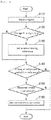
- the method of controlling opening and closing of a circuit breaker in accordance with one example embodiment of the present invention comprises, first of all, steps of receiving a signal as S110, detecting change in a sign of the signal as S120, setting a zero-crossing reference when there is any change in the sign as S130, checking whether the absolute value of an integral over a period obtained by integrating the signal over a period exceeds the zero-crossing reference or not as S140, determining whether the detected phase is identical to a set phase as S150, and controlling the opening or the closing of the circuit breaker when the absolute value of the integral over a period does not exceed the reference and the detected phase is identical to the set phase as S160.
- the reference as a specific positive value exceeding zero may be determined to be properly set depending on an environment and a situation of installing the circuit breaker such as amplitude of the signal or degree of noise.
- the set phase may be determined as a value between 0 degree and 360 degrees.
- the method of controlling the opening and closing of the circuit breaker in the present invention is applied to a circuit breaker for frequent phase modifying equipment switching that cuts off a voltage level of at least 1 kV.
- the circuit breaker detects a zero-crossing regarding an inputted signal and at the step of opening and closing the circuit breaker as S160, the circuit breaker is controlled to be opened and closed at a set phase but at the time, when the zero-crossing occurs due to noise, a delay in controlling an opening and closing device occurs over at least one period because setting a zero-crossing reference is performed again at the step of setting the zero-crossing reference as S130.
- the absolute value of an integral over a period does not exceed a reference value at a step of comparing the integral over a period as $140 by making the integral based on the zero-crossing to minimize such delay in the present invention, to minimize such delay, it may be ignored by being considered as the zero-crossing by noise and the circuit breaker may be opened and closed at a set phase without any noise impact.
- the reference as a specific positive value exceeding zero may be determined to be properly set depending on an environment and a situation of installing the circuit breaker such as amplitude of the signal or degree of noise.
- Fig. 2 is a drawing representing a case where a signal is distorted by noise.
- a normal zero-crossing 250 in a voltage waveform 210 occurs every period.
- a normal integral waveform 240 as an integral of a signal over a period becomes zero, opening and closing of the circuit breaker may be controlled based on the normal zero-crossing 250.
- an abnormal zero-crossing 260 occurs by noise, an abnormal integral waveform 270 as an integral of the signal over a period does not become zero any longer and if the circuit breaker is controlled based on the abnormal zero-crossing 260, the circuit breaker may be damaged. Accordingly, the opening and closing of the circuit breaker may be controlled to prevent such damage by detecting the zero-crossing again but in this case, a delay over as much as a period may occur.
- the abnormal integral waveform 270 does not exceed a reference 230, i.e., if the abnormal value of the integral over a period by integrating the signal over one period based on the zero-crossing does not exceed the reference 230, the abnormal zero-crossing 260 is determined as zero-crossing caused by noise, thereby being ignored. After that, the opening and closing of the circuit breaker is controlled based on the normal zero-crossing 250.
- the method of controlling the opening and closing of the circuit breaker in the present invention may allow the opening and closing of the circuit breaker to be controlled without any delay over a period.
- Fig. 3 shows drawings representing cases where the present invention is applied to a signal in Fig. 2 and where a conventional method is applied, wherein a set phase is -90 degrees, i.e., 270 degrees.
- an abnormal zero-crossing 360 other than a normal zero-crossing 350 caused by noise may occur.
- a next zero-crossing 370 is detected again.
- the opening and closing of the circuit breaker is controlled after a phase is detected 371 based on a next zero-crossing 370 and whether the phase is identical to a set phase is checked, the control is delayed.
- the present invention may prevent such delay by ignoring the abnormal zero-crossing 360 caused by noise even though the normal zero-crossing 350 and the abnormal zero-crossing 360 are detected, checking whether a phase detected 351 based on the normal zero-crossing 350 is identical to the set phase, and controlling the opening and closing of the circuit breaker.
- the present invention may control the circuit breaker without any delay even though the abnormal zero-crossing 360 caused by noise occurs.
- Fig. 4 is a block diagram representing a device for controlling opening and closing of a circuit breaker in accordance with one example embodiment of the present invention.
- the device for controlling opening and closing of the circuit breaker in the prevent invention includes a signal inputting unit 410 for receiving a signal, a unit 420 for opening and closing the circuit breaker, a zero-crossing detecting unit 430 for detecting change in a sign of the signal, and a control unit 440 for setting a zero-crossing reference when there is any change in the sign, checking whether the absolute value of an integral over a period obtained by integrating the signal over a period exceeds the zero-crossing reference or not, determining whether the detected phase is identical to a set phase, and thereby controlling a unit 420 for opening or closing a circuit breaker when the absolute value of the integral over a period does not exceed the reference and the detected phase is identical to the set phase.
- the reference as a specific positive value exceeding zero may be determined to be properly set depending on an environment and a situation of installing the circuit breaker such as amplitude of the signal or degree of noise and the set phase may be determined as a value between 0 degree and 360 degrees.
- the device for controlling opening and closing of the circuit breaker in the present invention is applied to a circuit breaker for frequent phase modifying equipment switching that cuts off a voltage level of at least 1 kV.
- the device for controlling opening and closing of the circuit breaker in the present invention first detects zero-crossing from a sign of the signal through the zero-crossing detecting unit 430 for detecting with respect to the inputted signal through the signal inputting unit 410.
- control unit 440 controls the opening and closing of the circuit breaker at a set phase through the unit 420 for opening and closing the circuit breaker.
- the device for controlling opening and closing of the circuit breaker in the present invention may control the circuit breaker without any delay even though an abnormal zero-crossing caused by noise occurs.
- the method of, and the device for, controlling opening and closing the circuit breaker in accordance with the present invention may protect phase modifying equipment by performing a reliable operation without malfunction even in the poor environment of a substation.
- the method of, and the device for, controlling opening and closing the circuit breaker in accordance with the present invention may control the circuit breaker by minimizing the noise impact upon the zero-crossing detect.
- the present invention has an effect of protecting phase modifying equipment by performing a reliable operation without malfunction even in the poor environment of a substation while being capable of operating the circuit breaker without any delay by minimizing noise impact upon zero-crossing detect based on the integral over a period.
- the present invention which relates to a method of, and a device for, controlling opening and closing of a circuit breaker is available in a field of circuit breaker.
Landscapes
- Engineering & Computer Science (AREA)
- Power Engineering (AREA)
- Physics & Mathematics (AREA)
- General Physics & Mathematics (AREA)
- Driving Mechanisms And Operating Circuits Of Arc-Extinguishing High-Tension Switches (AREA)
- Keying Circuit Devices (AREA)
Abstract
Description
- The present invention relates to a method of, and a device for, controlling opening and closing a circuit breaker, and more particularly, to controlling the circuit breaker by minimizing noise impact on a zero-crossing detect. In other words, the present invention relates to the method of, and the device for, controlling the opening and closing of the circuit breaker without any delay by minimizing noise impact over the zero-crossing detect.
- In general, a circuit breaker or CB refers to a device of keeping safety by performing a function of supplying which supplies power to load and a function of opening which turns off a load circuit upon fault occurrence.
- Generally, because a sinusoidal AC waveform is mainly used for a power line of a power grid, when a circuit breaker is suddenly opened, a switching surge such as an arc caused by transients may occur on the circuit breaker. Such opening and closing surge may shorten the lifecycle of the circuit breaker by degrading its performance. In addition, when the time goes by, the circuit breaker becomes obsolete, it is impossible to accurately open and close the circuit breaker. Therefore, a lot of studies on technology of controlling opening and closing of a circuit breaker have been made.
- For example, Korean Patent Laid-Open Publication No.
10-2005-0117193 - However, even in this case, it is impossible to prevent the noise impact over the zero-crossing detect. Therefore, it may delay controlling the opening and closing of the circuit breaker or cause a malfunction thereof.
- It is an object of the present invention to provide a method of, and a device for, controlling opening and closing a circuit breaker by minimizing noise impact over a zero-crossing detect.
- It is the other object of the present invention to provide a method of, and a device for, controlling a circuit breaker that protects phase modifying equipment by performing a reliable operation without malfunction even in a poor environment of a substation while operating the circuit breaker without any delay by minimizing noise impact over zero-crossing detect based on an integral over a period.
- The drawings attached below to explain example embodiments of the present invention are only part of example embodiments of the present invention and other drawings may be obtained based on the drawings without inventive work for those skilled in the art:
-
Fig. 1 is a flowchart representing a method of controlling opening and closing a circuit breaker in accordance with one example embodiment of the present invention. -
Fig. 2 is a drawing representing a case where a signal is distorted by noise. -
Fig. 3 shows drawings representing cases where the present invention is applied to a signal inFig. 2 and where a conventional method is applied. -
Fig. 4 is a block diagram representing a device for controlling opening and closing of a circuit breaker in accordance with one example embodiment of the present invention. - Explanation of detailed example embodiments to execute the present invention is made by referring to attached drawings.
- The present invention may make alternations and have several example embodiments. Therefore, specific example embodiments will be exemplified in drawings and used for detailed explanation. It may be understood that this is not intended to limit the present invention to the specific example embodiments and include all modifications, equivalents or alternatives included in the spirit and technical scope of the present invention.
- A method of, and a device for, controlling opening and closing of a circuit breaker in accordance with the present invention are explained below in details by referring to attached drawings.
-
Fig. 1 is a flowchart representing a method of controlling opening and closing a circuit breaker in accordance with one example embodiment of the present invention andFigs. 2 and3 are graphs to explainFig. 1 in details. - By referring to
Figs. 1 to 3 , the method of controlling the opening and closing of the circuit breaker in accordance with one example embodiment of the present invention is explained. - By referring to
Fig. 1 , the method of controlling opening and closing of a circuit breaker in accordance with one example embodiment of the present invention comprises, first of all, steps of receiving a signal as S110, detecting change in a sign of the signal as S120, setting a zero-crossing reference when there is any change in the sign as S130, checking whether the absolute value of an integral over a period obtained by integrating the signal over a period exceeds the zero-crossing reference or not as S140, determining whether the detected phase is identical to a set phase as S150, and controlling the opening or the closing of the circuit breaker when the absolute value of the integral over a period does not exceed the reference and the detected phase is identical to the set phase as S160. - Herein, the reference as a specific positive value exceeding zero may be determined to be properly set depending on an environment and a situation of installing the circuit breaker such as amplitude of the signal or degree of noise. Besides, the set phase may be determined as a value between 0 degree and 360 degrees.
- Meanwhile, it is desirable that the method of controlling the opening and closing of the circuit breaker in the present invention is applied to a circuit breaker for frequent phase modifying equipment switching that cuts off a voltage level of at least 1 kV.
- In case of the conventional method of controlling the opening and closing of the circuit breaker, at the step of detecting the change in the sign as S120, the circuit breaker detects a zero-crossing regarding an inputted signal and at the step of opening and closing the circuit breaker as S160, the circuit breaker is controlled to be opened and closed at a set phase but at the time, when the zero-crossing occurs due to noise, a delay in controlling an opening and closing device occurs over at least one period because setting a zero-crossing reference is performed again at the step of setting the zero-crossing reference as S130.
- Accordingly, when the absolute value of an integral over a period does not exceed a reference value at a step of comparing the integral over a period as $140 by making the integral based on the zero-crossing to minimize such delay in the present invention, to minimize such delay, it may be ignored by being considered as the zero-crossing by noise and the circuit breaker may be opened and closed at a set phase without any noise impact.
- At the time, as explained above, the reference as a specific positive value exceeding zero may be determined to be properly set depending on an environment and a situation of installing the circuit breaker such as amplitude of the signal or degree of noise.
-
Fig. 2 is a drawing representing a case where a signal is distorted by noise. In general, a normal zero-crossing 250 in avoltage waveform 210 occurs every period. At this time, because a normalintegral waveform 240 as an integral of a signal over a period becomes zero, opening and closing of the circuit breaker may be controlled based on the normal zero-crossing 250. - But, as shown in
Fig. 2 , if an abnormal zero-crossing 260 occurs by noise, an abnormalintegral waveform 270 as an integral of the signal over a period does not become zero any longer and if the circuit breaker is controlled based on the abnormal zero-crossing 260, the circuit breaker may be damaged. Accordingly, the opening and closing of the circuit breaker may be controlled to prevent such damage by detecting the zero-crossing again but in this case, a delay over as much as a period may occur. - Therefore, in the present invention, if the abnormal
integral waveform 270 does not exceed areference 230, i.e., if the abnormal value of the integral over a period by integrating the signal over one period based on the zero-crossing does not exceed thereference 230, the abnormal zero-crossing 260 is determined as zero-crossing caused by noise, thereby being ignored. After that, the opening and closing of the circuit breaker is controlled based on the normal zero-crossing 250. - The method of controlling the opening and closing of the circuit breaker in the present invention may allow the opening and closing of the circuit breaker to be controlled without any delay over a period.
-
Fig. 3 shows drawings representing cases where the present invention is applied to a signal inFig. 2 and where a conventional method is applied, wherein a set phase is -90 degrees, i.e., 270 degrees. - As shown in
Fig. 3A , along an inputtedsignal 320 of the opening and closing device, an abnormal zero-crossing 360 other than a normal zero-crossing 350 caused by noise may occur. - According to the conventional method, when an abnormal zero-
crossing 360 is detected, a next zero-crossing 370 is detected again. As seen inFig. 3B , as the opening and closing of the circuit breaker is controlled after a phase is detected 371 based on a next zero-crossing 370 and whether the phase is identical to a set phase is checked, the control is delayed. - On the other hand, as seen in
Fig. 3C , the present invention may prevent such delay by ignoring the abnormal zero-crossing 360 caused by noise even though the normal zero-crossing 350 and the abnormal zero-crossing 360 are detected, checking whether a phase detected 351 based on the normal zero-crossing 350 is identical to the set phase, and controlling the opening and closing of the circuit breaker. - Accordingly, the present invention may control the circuit breaker without any delay even though the abnormal zero-
crossing 360 caused by noise occurs. -
Fig. 4 is a block diagram representing a device for controlling opening and closing of a circuit breaker in accordance with one example embodiment of the present invention. - As seen in
Fig. 4 , the device for controlling opening and closing of the circuit breaker in the prevent invention includes asignal inputting unit 410 for receiving a signal, aunit 420 for opening and closing the circuit breaker, a zero-crossing detecting unit 430 for detecting change in a sign of the signal, and acontrol unit 440 for setting a zero-crossing reference when there is any change in the sign, checking whether the absolute value of an integral over a period obtained by integrating the signal over a period exceeds the zero-crossing reference or not, determining whether the detected phase is identical to a set phase, and thereby controlling aunit 420 for opening or closing a circuit breaker when the absolute value of the integral over a period does not exceed the reference and the detected phase is identical to the set phase. - As explained above, herein, the reference as a specific positive value exceeding zero may be determined to be properly set depending on an environment and a situation of installing the circuit breaker such as amplitude of the signal or degree of noise and the set phase may be determined as a value between 0 degree and 360 degrees. In addition, it is desirable that the device for controlling opening and closing of the circuit breaker in the present invention is applied to a circuit breaker for frequent phase modifying equipment switching that cuts off a voltage level of at least 1 kV.
- The device for controlling opening and closing of the circuit breaker in the present invention first detects zero-crossing from a sign of the signal through the zero-
crossing detecting unit 430 for detecting with respect to the inputted signal through thesignal inputting unit 410. - After that, when integration is made based on the zero-crossing and the absolute value of an integral over one period does not exceed a reference value, the
control unit 440 controls the opening and closing of the circuit breaker at a set phase through theunit 420 for opening and closing the circuit breaker. - Accordingly, the device for controlling opening and closing of the circuit breaker in the present invention may control the circuit breaker without any delay even though an abnormal zero-crossing caused by noise occurs.
- As seen above, while being capable of operating the circuit breaker without any delay by minimizing noise impact upon zero-crossing detect based on the integral over a period, the method of, and the device for, controlling opening and closing the circuit breaker in accordance with the present invention may protect phase modifying equipment by performing a reliable operation without malfunction even in the poor environment of a substation.
- The method of, and the device for, controlling opening and closing the circuit breaker in accordance with the present invention may control the circuit breaker by minimizing the noise impact upon the zero-crossing detect.
- Furthermore, the present invention has an effect of protecting phase modifying equipment by performing a reliable operation without malfunction even in the poor environment of a substation while being capable of operating the circuit breaker without any delay by minimizing noise impact upon zero-crossing detect based on the integral over a period.
- What has been explained above includes at least one example embodiment. Of course, it cannot be recognized that all possible combinations of components or methods for the purpose of explaining the aforementioned example embodiments but it can be perceived that those skilled in the art may make a lot of additions and replacements of various example embodiments. Accordingly, the explained example embodiments include all alternatives, modifications, and changes without departing from the spirit and scope of the invention as defined in the following claims.
- The present invention which relates to a method of, and a device for, controlling opening and closing of a circuit breaker is available in a field of circuit breaker.
Claims (10)
- A method of controlling opening and closing of a circuit breaker, comprising steps of:receiving an inputted signal;detecting change in a sign of the signal;setting a zero-crossing reference when there is any change in the sign;checking whether the absolute value of an integral over a period obtained by integrating the signal over a period exceeds the zero-crossing reference or not; anddetermining whether the detected phase is identical to a set phase; andcontrolling the opening or the closing of the circuit breaker when the absolute value of the integral over a period does not exceed the reference and the detected phase is identical to the set phase.
- The method of Claim 1, wherein, at the step of comparing the integral over a period, the reference is a specific positive value exceeding zero.
- The method of Claim 1, wherein, at the step of comparing the integral over a period, the reference is determined based on at least either of amplitude of the signal or degree of noise.
- The method of Claim 3, wherein the set phase is a value between 0 degree and 360 degrees.
- The method of Claim 1, wherein the circuit breaker is a circuit breaker for frequent phase modifying equipment switching that cuts off a voltage level of at least 1 kV.
- A device for controlling opening and closing of a circuit breaker, comprising:a signal inputting unit for receiving a signal;a unit for opening and closing the circuit breaker;a zero-crossing detecting unit for detecting change in a sign of the signal; anda control unit for setting a zero-crossing reference when there is any change in the sign, checking whether the absolute value of an integral over a period obtained by integrating the signal over a period exceeds the zero-crossing reference or not, determining whether the detected phase is identical to a set phase, and thereby controlling the opening or the closing of the circuit breaker when the absolute value of the integral over a period does not exceed the reference and the detected phase is identical to the set phase.
- The device of Claim 6, wherein the reference is a specific positive value exceeding zero.
- The device of Claim 6, wherein the reference is determined based on at least either of amplitude of the signal or degree of noise.
- The device of Claim 6, wherein the set phase is a value between 0 degree and 360 degrees.
- The device of Claim 6, wherein the circuit breaker is a circuit breaker for frequent phase modifying equipment switching that cuts off a voltage level of at least 1 kV.
Applications Claiming Priority (2)
| Application Number | Priority Date | Filing Date | Title |
|---|---|---|---|
| KR1020150190257A KR101793061B1 (en) | 2015-12-30 | 2015-12-30 | Device and method for circuit breaker control |
| PCT/KR2016/015211 WO2017116086A1 (en) | 2015-12-30 | 2016-12-23 | Method and device for controlling opening/closing of circuit breaker |
Publications (3)
| Publication Number | Publication Date |
|---|---|
| EP3399533A1 true EP3399533A1 (en) | 2018-11-07 |
| EP3399533A4 EP3399533A4 (en) | 2019-09-18 |
| EP3399533B1 EP3399533B1 (en) | 2020-10-21 |
Family
ID=59225338
Family Applications (1)
| Application Number | Title | Priority Date | Filing Date |
|---|---|---|---|
| EP16882038.9A Active EP3399533B1 (en) | 2015-12-30 | 2016-12-23 | Method and device for controlling opening/closing of circuit breaker |
Country Status (4)
| Country | Link |
|---|---|
| US (1) | US20190027917A1 (en) |
| EP (1) | EP3399533B1 (en) |
| KR (1) | KR101793061B1 (en) |
| WO (1) | WO2017116086A1 (en) |
Family Cites Families (13)
| Publication number | Priority date | Publication date | Assignee | Title |
|---|---|---|---|---|
| DE1090289B (en) * | 1958-01-09 | 1960-10-06 | Siemens Ag | Control unit for AC switch |
| US4045822A (en) * | 1976-05-03 | 1977-08-30 | Rca Corporation | Ground fault interrupter apparatus |
| JP2892717B2 (en) * | 1989-11-15 | 1999-05-17 | 株式会社日立製作所 | Power switching controller |
| US5644463A (en) * | 1992-10-20 | 1997-07-01 | University Of Washington | Adaptive sequential controller with minimum switching energy |
| KR101064744B1 (en) * | 2005-12-02 | 2011-09-16 | 현대중공업 주식회사 | Controlled switching device using FET driver for circuit breaker |
| US7904266B2 (en) * | 2007-05-22 | 2011-03-08 | Abb Technology Ag | Method and apparatus for calculating the separation time of arcing contacts of a high-volume switchgear |
| KR101036544B1 (en) * | 2008-06-27 | 2011-05-24 | 이만실 | Apparatus for monitoring of circuit breaker in power system |
| JP2011015583A (en) * | 2009-07-06 | 2011-01-20 | Fuji Electric Fa Components & Systems Co Ltd | Leakage detection method, leakage detection device, and earth leakage breaker |
| KR101089441B1 (en) * | 2009-12-28 | 2011-12-07 | 주식회사 효성 | Monitoring and Diagnostic System for Air-Type Operating Equipment of Switchgear |
| JP5472912B2 (en) * | 2010-02-19 | 2014-04-16 | 株式会社東芝 | Overvoltage suppression device |
| WO2012014282A1 (en) * | 2010-07-27 | 2012-02-02 | 三菱電機株式会社 | Phase control switchgear |
| JP6099896B2 (en) * | 2012-07-19 | 2017-03-22 | 株式会社東芝 | Exciting inrush current suppressing device and its suppressing method |
| KR20150142546A (en) * | 2014-06-12 | 2015-12-22 | 윈텍전기 주식회사 | Electromagnetic contactor and control method thereof |
-
2015
- 2015-12-30 KR KR1020150190257A patent/KR101793061B1/en active IP Right Grant
-
2016
- 2016-12-23 EP EP16882038.9A patent/EP3399533B1/en active Active
- 2016-12-23 WO PCT/KR2016/015211 patent/WO2017116086A1/en active Application Filing
- 2016-12-23 US US16/067,397 patent/US20190027917A1/en not_active Abandoned
Also Published As
| Publication number | Publication date |
|---|---|
| KR20170079554A (en) | 2017-07-10 |
| KR101793061B1 (en) | 2017-11-02 |
| WO2017116086A1 (en) | 2017-07-06 |
| EP3399533A4 (en) | 2019-09-18 |
| EP3399533B1 (en) | 2020-10-21 |
| US20190027917A1 (en) | 2019-01-24 |
Similar Documents
| Publication | Publication Date | Title |
|---|---|---|
| KR20150128124A (en) | Over current relay | |
| US8284531B2 (en) | Voltage protection arrangement for an electronic device | |
| JP6895647B2 (en) | Arc detection circuit, switch system, power conditioner system and arc detection method | |
| KR101316544B1 (en) | Method for judging electric power system failure | |
| KR20140053668A (en) | Protection circuit and gate driving circuit for semiconductor switch device | |
| JP5567624B2 (en) | Protection coordination system | |
| JP2007043822A (en) | Overvoltage protection circuit | |
| US20170366040A1 (en) | Transfer switch apparatus and methods using transition time monitoring and adaptation | |
| JP5511599B2 (en) | Commutation type shut-off device | |
| EP3399533B1 (en) | Method and device for controlling opening/closing of circuit breaker | |
| EP3916407A1 (en) | Dual pwm relay driver with diagnostics for functional safety system | |
| AU2015202553B2 (en) | Hermetic compressor driving device | |
| KR101291767B1 (en) | Switchboards with standby power cut off functions | |
| JP6618081B2 (en) | Power converter | |
| US20130182354A1 (en) | Overvoltage protection during gcu failure | |
| KR102333786B1 (en) | Apparatus and method for auto transfer of motor bus | |
| JP6919808B2 (en) | Overcurrent suppression device and DC power distribution system | |
| US10759546B2 (en) | Transient voltage suppression protection circuit including built in testing and enable-disable functionality | |
| KR20070057572A (en) | Controlled switching device using fet driver for circuit breaker | |
| KR102514585B1 (en) | Digital protection relay and controlling method thereof | |
| KR101877234B1 (en) | Over current blocking system and a method for blocking over current using the same | |
| KR20200025391A (en) | Differential protective apparatus and method to prevent malfunction by digital protection relay's internal computation error | |
| KR102240393B1 (en) | Power control system and method for detecting fuse disconnection | |
| JP5885155B2 (en) | Backup device and backup method | |
| KR101631637B1 (en) | Fault current limiter |
Legal Events
| Date | Code | Title | Description |
|---|---|---|---|
| STAA | Information on the status of an ep patent application or granted ep patent |
Free format text: STATUS: THE INTERNATIONAL PUBLICATION HAS BEEN MADE |
|
| PUAI | Public reference made under article 153(3) epc to a published international application that has entered the european phase |
Free format text: ORIGINAL CODE: 0009012 |
|
| STAA | Information on the status of an ep patent application or granted ep patent |
Free format text: STATUS: REQUEST FOR EXAMINATION WAS MADE |
|
| 17P | Request for examination filed |
Effective date: 20180713 |
|
| AK | Designated contracting states |
Kind code of ref document: A1 Designated state(s): AL AT BE BG CH CY CZ DE DK EE ES FI FR GB GR HR HU IE IS IT LI LT LU LV MC MK MT NL NO PL PT RO RS SE SI SK SM TR |
|
| AX | Request for extension of the european patent |
Extension state: BA ME |
|
| RAP1 | Party data changed (applicant data changed or rights of an application transferred) |
Owner name: HYOSUNG HEAVY INDUSTRIES CORPORATION |
|
| DAV | Request for validation of the european patent (deleted) | ||
| DAX | Request for extension of the european patent (deleted) | ||
| A4 | Supplementary search report drawn up and despatched |
Effective date: 20190821 |
|
| RIC1 | Information provided on ipc code assigned before grant |
Ipc: H02H 3/00 20060101ALI20190814BHEP Ipc: H01H 33/59 20060101ALI20190814BHEP Ipc: H02H 3/353 20060101ALI20190814BHEP Ipc: H01H 9/54 20060101AFI20190814BHEP Ipc: G01R 19/175 20060101ALI20190814BHEP Ipc: G01R 19/165 20060101ALI20190814BHEP Ipc: H02H 3/02 20060101ALI20190814BHEP |
|
| GRAP | Despatch of communication of intention to grant a patent |
Free format text: ORIGINAL CODE: EPIDOSNIGR1 |
|
| STAA | Information on the status of an ep patent application or granted ep patent |
Free format text: STATUS: GRANT OF PATENT IS INTENDED |
|
| INTG | Intention to grant announced |
Effective date: 20200512 |
|
| GRAS | Grant fee paid |
Free format text: ORIGINAL CODE: EPIDOSNIGR3 |
|
| GRAA | (expected) grant |
Free format text: ORIGINAL CODE: 0009210 |
|
| STAA | Information on the status of an ep patent application or granted ep patent |
Free format text: STATUS: THE PATENT HAS BEEN GRANTED |
|
| AK | Designated contracting states |
Kind code of ref document: B1 Designated state(s): AL AT BE BG CH CY CZ DE DK EE ES FI FR GB GR HR HU IE IS IT LI LT LU LV MC MK MT NL NO PL PT RO RS SE SI SK SM TR |
|
| REG | Reference to a national code |
Ref country code: GB Ref legal event code: FG4D |
|
| REG | Reference to a national code |
Ref country code: CH Ref legal event code: EP |
|
| REG | Reference to a national code |
Ref country code: IE Ref legal event code: FG4D |
|
| REG | Reference to a national code |
Ref country code: AT Ref legal event code: REF Ref document number: 1326699 Country of ref document: AT Kind code of ref document: T Effective date: 20201115 |
|
| REG | Reference to a national code |
Ref country code: DE Ref legal event code: R096 Ref document number: 602016046495 Country of ref document: DE |
|
| REG | Reference to a national code |
Ref country code: AT Ref legal event code: MK05 Ref document number: 1326699 Country of ref document: AT Kind code of ref document: T Effective date: 20201021 |
|
| REG | Reference to a national code |
Ref country code: NL Ref legal event code: MP Effective date: 20201021 |
|
| PG25 | Lapsed in a contracting state [announced via postgrant information from national office to epo] |
Ref country code: RS Free format text: LAPSE BECAUSE OF FAILURE TO SUBMIT A TRANSLATION OF THE DESCRIPTION OR TO PAY THE FEE WITHIN THE PRESCRIBED TIME-LIMIT Effective date: 20201021 Ref country code: PT Free format text: LAPSE BECAUSE OF FAILURE TO SUBMIT A TRANSLATION OF THE DESCRIPTION OR TO PAY THE FEE WITHIN THE PRESCRIBED TIME-LIMIT Effective date: 20210222 Ref country code: NO Free format text: LAPSE BECAUSE OF FAILURE TO SUBMIT A TRANSLATION OF THE DESCRIPTION OR TO PAY THE FEE WITHIN THE PRESCRIBED TIME-LIMIT Effective date: 20210121 Ref country code: FI Free format text: LAPSE BECAUSE OF FAILURE TO SUBMIT A TRANSLATION OF THE DESCRIPTION OR TO PAY THE FEE WITHIN THE PRESCRIBED TIME-LIMIT Effective date: 20201021 Ref country code: GR Free format text: LAPSE BECAUSE OF FAILURE TO SUBMIT A TRANSLATION OF THE DESCRIPTION OR TO PAY THE FEE WITHIN THE PRESCRIBED TIME-LIMIT Effective date: 20210122 |
|
| REG | Reference to a national code |
Ref country code: LT Ref legal event code: MG4D |
|
| PG25 | Lapsed in a contracting state [announced via postgrant information from national office to epo] |
Ref country code: SE Free format text: LAPSE BECAUSE OF FAILURE TO SUBMIT A TRANSLATION OF THE DESCRIPTION OR TO PAY THE FEE WITHIN THE PRESCRIBED TIME-LIMIT Effective date: 20201021 Ref country code: AT Free format text: LAPSE BECAUSE OF FAILURE TO SUBMIT A TRANSLATION OF THE DESCRIPTION OR TO PAY THE FEE WITHIN THE PRESCRIBED TIME-LIMIT Effective date: 20201021 Ref country code: ES Free format text: LAPSE BECAUSE OF FAILURE TO SUBMIT A TRANSLATION OF THE DESCRIPTION OR TO PAY THE FEE WITHIN THE PRESCRIBED TIME-LIMIT Effective date: 20201021 Ref country code: BG Free format text: LAPSE BECAUSE OF FAILURE TO SUBMIT A TRANSLATION OF THE DESCRIPTION OR TO PAY THE FEE WITHIN THE PRESCRIBED TIME-LIMIT Effective date: 20210121 Ref country code: PL Free format text: LAPSE BECAUSE OF FAILURE TO SUBMIT A TRANSLATION OF THE DESCRIPTION OR TO PAY THE FEE WITHIN THE PRESCRIBED TIME-LIMIT Effective date: 20201021 Ref country code: IS Free format text: LAPSE BECAUSE OF FAILURE TO SUBMIT A TRANSLATION OF THE DESCRIPTION OR TO PAY THE FEE WITHIN THE PRESCRIBED TIME-LIMIT Effective date: 20210221 Ref country code: LV Free format text: LAPSE BECAUSE OF FAILURE TO SUBMIT A TRANSLATION OF THE DESCRIPTION OR TO PAY THE FEE WITHIN THE PRESCRIBED TIME-LIMIT Effective date: 20201021 |
|
| PG25 | Lapsed in a contracting state [announced via postgrant information from national office to epo] |
Ref country code: HR Free format text: LAPSE BECAUSE OF FAILURE TO SUBMIT A TRANSLATION OF THE DESCRIPTION OR TO PAY THE FEE WITHIN THE PRESCRIBED TIME-LIMIT Effective date: 20201021 Ref country code: NL Free format text: LAPSE BECAUSE OF FAILURE TO SUBMIT A TRANSLATION OF THE DESCRIPTION OR TO PAY THE FEE WITHIN THE PRESCRIBED TIME-LIMIT Effective date: 20201021 |
|
| REG | Reference to a national code |
Ref country code: DE Ref legal event code: R119 Ref document number: 602016046495 Country of ref document: DE |
|
| PG25 | Lapsed in a contracting state [announced via postgrant information from national office to epo] |
Ref country code: SK Free format text: LAPSE BECAUSE OF FAILURE TO SUBMIT A TRANSLATION OF THE DESCRIPTION OR TO PAY THE FEE WITHIN THE PRESCRIBED TIME-LIMIT Effective date: 20201021 Ref country code: RO Free format text: LAPSE BECAUSE OF FAILURE TO SUBMIT A TRANSLATION OF THE DESCRIPTION OR TO PAY THE FEE WITHIN THE PRESCRIBED TIME-LIMIT Effective date: 20201021 Ref country code: SM Free format text: LAPSE BECAUSE OF FAILURE TO SUBMIT A TRANSLATION OF THE DESCRIPTION OR TO PAY THE FEE WITHIN THE PRESCRIBED TIME-LIMIT Effective date: 20201021 Ref country code: LT Free format text: LAPSE BECAUSE OF FAILURE TO SUBMIT A TRANSLATION OF THE DESCRIPTION OR TO PAY THE FEE WITHIN THE PRESCRIBED TIME-LIMIT Effective date: 20201021 Ref country code: EE Free format text: LAPSE BECAUSE OF FAILURE TO SUBMIT A TRANSLATION OF THE DESCRIPTION OR TO PAY THE FEE WITHIN THE PRESCRIBED TIME-LIMIT Effective date: 20201021 Ref country code: CZ Free format text: LAPSE BECAUSE OF FAILURE TO SUBMIT A TRANSLATION OF THE DESCRIPTION OR TO PAY THE FEE WITHIN THE PRESCRIBED TIME-LIMIT Effective date: 20201021 |
|
| REG | Reference to a national code |
Ref country code: CH Ref legal event code: PL |
|
| PLBE | No opposition filed within time limit |
Free format text: ORIGINAL CODE: 0009261 |
|
| STAA | Information on the status of an ep patent application or granted ep patent |
Free format text: STATUS: NO OPPOSITION FILED WITHIN TIME LIMIT |
|
| PG25 | Lapsed in a contracting state [announced via postgrant information from national office to epo] |
Ref country code: MC Free format text: LAPSE BECAUSE OF FAILURE TO SUBMIT A TRANSLATION OF THE DESCRIPTION OR TO PAY THE FEE WITHIN THE PRESCRIBED TIME-LIMIT Effective date: 20201021 Ref country code: DK Free format text: LAPSE BECAUSE OF FAILURE TO SUBMIT A TRANSLATION OF THE DESCRIPTION OR TO PAY THE FEE WITHIN THE PRESCRIBED TIME-LIMIT Effective date: 20201021 |
|
| REG | Reference to a national code |
Ref country code: BE Ref legal event code: MM Effective date: 20201231 |
|
| 26N | No opposition filed |
Effective date: 20210722 |
|
| GBPC | Gb: european patent ceased through non-payment of renewal fee |
Effective date: 20210121 |
|
| PG25 | Lapsed in a contracting state [announced via postgrant information from national office to epo] |
Ref country code: FR Free format text: LAPSE BECAUSE OF NON-PAYMENT OF DUE FEES Effective date: 20201231 Ref country code: IT Free format text: LAPSE BECAUSE OF FAILURE TO SUBMIT A TRANSLATION OF THE DESCRIPTION OR TO PAY THE FEE WITHIN THE PRESCRIBED TIME-LIMIT Effective date: 20201021 Ref country code: LU Free format text: LAPSE BECAUSE OF NON-PAYMENT OF DUE FEES Effective date: 20201223 Ref country code: AL Free format text: LAPSE BECAUSE OF FAILURE TO SUBMIT A TRANSLATION OF THE DESCRIPTION OR TO PAY THE FEE WITHIN THE PRESCRIBED TIME-LIMIT Effective date: 20201021 Ref country code: IE Free format text: LAPSE BECAUSE OF NON-PAYMENT OF DUE FEES Effective date: 20201223 |
|
| PG25 | Lapsed in a contracting state [announced via postgrant information from national office to epo] |
Ref country code: SI Free format text: LAPSE BECAUSE OF FAILURE TO SUBMIT A TRANSLATION OF THE DESCRIPTION OR TO PAY THE FEE WITHIN THE PRESCRIBED TIME-LIMIT Effective date: 20201021 Ref country code: CH Free format text: LAPSE BECAUSE OF NON-PAYMENT OF DUE FEES Effective date: 20201231 Ref country code: DE Free format text: LAPSE BECAUSE OF NON-PAYMENT OF DUE FEES Effective date: 20210701 Ref country code: LI Free format text: LAPSE BECAUSE OF NON-PAYMENT OF DUE FEES Effective date: 20201231 Ref country code: GB Free format text: LAPSE BECAUSE OF NON-PAYMENT OF DUE FEES Effective date: 20210121 |
|
| PG25 | Lapsed in a contracting state [announced via postgrant information from national office to epo] |
Ref country code: IS Free format text: LAPSE BECAUSE OF FAILURE TO SUBMIT A TRANSLATION OF THE DESCRIPTION OR TO PAY THE FEE WITHIN THE PRESCRIBED TIME-LIMIT Effective date: 20210221 Ref country code: TR Free format text: LAPSE BECAUSE OF FAILURE TO SUBMIT A TRANSLATION OF THE DESCRIPTION OR TO PAY THE FEE WITHIN THE PRESCRIBED TIME-LIMIT Effective date: 20201021 Ref country code: MT Free format text: LAPSE BECAUSE OF FAILURE TO SUBMIT A TRANSLATION OF THE DESCRIPTION OR TO PAY THE FEE WITHIN THE PRESCRIBED TIME-LIMIT Effective date: 20201021 Ref country code: CY Free format text: LAPSE BECAUSE OF FAILURE TO SUBMIT A TRANSLATION OF THE DESCRIPTION OR TO PAY THE FEE WITHIN THE PRESCRIBED TIME-LIMIT Effective date: 20201021 |
|
| PG25 | Lapsed in a contracting state [announced via postgrant information from national office to epo] |
Ref country code: MK Free format text: LAPSE BECAUSE OF FAILURE TO SUBMIT A TRANSLATION OF THE DESCRIPTION OR TO PAY THE FEE WITHIN THE PRESCRIBED TIME-LIMIT Effective date: 20201021 |
|
| PG25 | Lapsed in a contracting state [announced via postgrant information from national office to epo] |
Ref country code: BE Free format text: LAPSE BECAUSE OF NON-PAYMENT OF DUE FEES Effective date: 20201231 |