EP3399476B1 - Strömungsmaschine zum aufbauen von automatisierten abläufen innerhalb einer cloud-basierten entwicklungsplattform - Google Patents
Strömungsmaschine zum aufbauen von automatisierten abläufen innerhalb einer cloud-basierten entwicklungsplattform Download PDFInfo
- Publication number
- EP3399476B1 EP3399476B1 EP17194240.2A EP17194240A EP3399476B1 EP 3399476 B1 EP3399476 B1 EP 3399476B1 EP 17194240 A EP17194240 A EP 17194240A EP 3399476 B1 EP3399476 B1 EP 3399476B1
- Authority
- EP
- European Patent Office
- Prior art keywords
- action
- flow plan
- run
- flow
- ready
- Prior art date
- Legal status (The legal status is an assumption and is not a legal conclusion. Google has not performed a legal analysis and makes no representation as to the accuracy of the status listed.)
- Active
Links
Images




Classifications
-
- G—PHYSICS
- G05—CONTROLLING; REGULATING
- G05B—CONTROL OR REGULATING SYSTEMS IN GENERAL; FUNCTIONAL ELEMENTS OF SUCH SYSTEMS; MONITORING OR TESTING ARRANGEMENTS FOR SUCH SYSTEMS OR ELEMENTS
- G05B19/00—Program-control systems
- G05B19/02—Program-control systems electric
- G05B19/04—Program control other than numerical control, i.e. in sequence controllers or logic controllers
- G05B19/042—Program control other than numerical control, i.e. in sequence controllers or logic controllers using digital processors
- G05B19/0426—Programming the control sequence
-
- G—PHYSICS
- G06—COMPUTING OR CALCULATING; COUNTING
- G06Q—INFORMATION AND COMMUNICATION TECHNOLOGY [ICT] SPECIALLY ADAPTED FOR ADMINISTRATIVE, COMMERCIAL, FINANCIAL, MANAGERIAL OR SUPERVISORY PURPOSES; SYSTEMS OR METHODS SPECIALLY ADAPTED FOR ADMINISTRATIVE, COMMERCIAL, FINANCIAL, MANAGERIAL OR SUPERVISORY PURPOSES, NOT OTHERWISE PROVIDED FOR
- G06Q10/00—Administration; Management
- G06Q10/06—Resources, workflows, human or project management; Enterprise or organisation planning; Enterprise or organisation modelling
- G06Q10/063—Operations research, analysis or management
- G06Q10/0633—Workflow analysis
-
- G—PHYSICS
- G05—CONTROLLING; REGULATING
- G05B—CONTROL OR REGULATING SYSTEMS IN GENERAL; FUNCTIONAL ELEMENTS OF SUCH SYSTEMS; MONITORING OR TESTING ARRANGEMENTS FOR SUCH SYSTEMS OR ELEMENTS
- G05B19/00—Program-control systems
- G05B19/02—Program-control systems electric
- G05B19/04—Program control other than numerical control, i.e. in sequence controllers or logic controllers
- G05B19/048—Monitoring; Safety
-
- H—ELECTRICITY
- H04—ELECTRIC COMMUNICATION TECHNIQUE
- H04L—TRANSMISSION OF DIGITAL INFORMATION, e.g. TELEGRAPHIC COMMUNICATION
- H04L67/00—Network arrangements or protocols for supporting network services or applications
-
- G—PHYSICS
- G05—CONTROLLING; REGULATING
- G05B—CONTROL OR REGULATING SYSTEMS IN GENERAL; FUNCTIONAL ELEMENTS OF SUCH SYSTEMS; MONITORING OR TESTING ARRANGEMENTS FOR SUCH SYSTEMS OR ELEMENTS
- G05B2219/00—Program-control systems
- G05B2219/20—Pc systems
- G05B2219/26—Pc applications
- G05B2219/2642—Domotique, domestic, home control, automation, smart house
-
- H—ELECTRICITY
- H04—ELECTRIC COMMUNICATION TECHNIQUE
- H04L—TRANSMISSION OF DIGITAL INFORMATION, e.g. TELEGRAPHIC COMMUNICATION
- H04L67/00—Network arrangements or protocols for supporting network services or applications
- H04L67/01—Protocols
- H04L67/10—Protocols in which an application is distributed across nodes in the network
Definitions
- Cloud computing relates to the sharing of computing resources that are generally accessed via the Internet.
- the cloud computing infrastructure allows users, such as individuals and/or enterprises, to access a shared pool of computing resources, such as servers, storage devices, networks, applications, and/or other computing based services.
- users are able to access computing resources on demand that are located at remote locations in order to perform a variety computing functions that include storing and/or processing computing data.
- cloud computing provides flexibility in accessing cloud computing resources without accruing up-front costs, such as purchasing network equipment, and investing time in establishing a private network infrastructure. Instead, by utilizing cloud computing resources, users are able redirect their resources to focus on core enterprise functions.
- SaaS software as a service
- PaaS platform as a service
- SaaS is a delivery model that provides software as a service rather than an end product. Instead of utilizing a local network or individual software installations, software is typically licensed on a subscription basis, hosted on a remote machine, and accessed as needed. For example, users are generally able to access a variety of enterprise and/or information technology (IT) related software via a web browser.
- PaaS acts an extension of SaaS that goes beyond providing software services by offering customizability and expandability features to meet a user's needs.
- PaaS can provide a cloud based developmental platform for users to develop, modify, and/or customize applications and/or automating enterprise operations without maintaining network infrastructure and/or allocating computing resources normally associated with these functions.
- PaaS Within the context of automating enterprise, IT, and/or other organization-related functions (e.g., human resources (HR)), PaaS often provides users an array of tools to implement complex behaviors, such as enterprise rules, scheduled jobs, events, and scripts, to build automated processes and to integrate with third party systems.
- the tools for PaaS generally offer users a rich set of facilities for building automated processes for various enterprise, IT, and/or other organization-related functions, users typically implement custom scripts to perform the automated process.
- Requiring customized script to build automated processes may pose a challenge when attempting to address abstraction (e.g., providing domain-appropriate building blocks), code reuse (e.g., having defined application program interface (API) semantics), and/or codeless development.
- API application program interface
- computing system refers to a single electronic computing device that includes, but is not limited to a single computer, virtual machine, virtual container, host, server, laptop, and/or mobile device or to a plurality of electronic computing devices working together to perform the function described as being performed on or by the computing system.
- the term “medium” refers to one or more non-transitory physical media that together store the contents described as being stored thereon.
- Embodiments may include non-volatile secondary storage, read-only memory (ROM), and/or random-access memory (RAM).
- an application refers to one or more computing modules, programs, processes, workloads, threads and/or a set of computing instructions executed by a computing system.
- Example embodiments of an application include software modules, software objects, software instances and/or other types of executable code.
- flow plan refers to a configured, automated process for addressing one or more tasks.
- the tasks for the flow plan correspond to a variety of enterprise and/or other organization-relation functions. Categories of tasks that relate to enterprise and/or other organization functions include, but are not limited to HR operations, customer service, security protection, enterprise applications, IT management, and/or IT operation.
- flow plans are created from a developmental platform, such as a Web 2.0 developmental platform written in Java@ (JAVA is a registered trademark owned by Oracle America, Inc.).
- global state refers to one or more global parameters or global variables that are accessible for an entire application. Examples of parameters or variables for a global state include, but are not limited to process and task execution statuses and resource conditions.
- a centralized decision-making component such as a centralized controller, is able to track the global state and determine execution orders for operations within a workflow.
- a developmental platform includes a service hub system that constructs action flow plans and a flow engine that executes run-time versions of the action flow plans.
- the service hub system includes a flow designer user interface that presents to a user one or more actions and triggers for constructing an action flow plan, an action designer user interface that allows a user to construct actions out of action steps, and a web service API (e.g., Representational State Transfer (REST) API) to interface with a data model.
- REST Representational State Transfer
- the service hub system may call a flow builder API to generate a run-time version of the action flow plan based on the data model.
- a flow engine may execute the run-time flow plan without utilizing a global state to manage flow execution order. Instead, the flow engine may execute each operation within the run-time flow plan when it is ready to run and repopulates a queue as operations are executed until there are no remaining ready operations.
- An operation within the run-time flow plan may be ready to run when the operation's input values are ready and the flow engine has completed any predecessor operations.
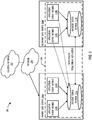
- FIG. 1 is a schematic diagram of an embodiment of a computing system 100, such as a cloud computing system, where embodiments of the present disclosure may operate herein.
- Computing system 100 may include a customer network 102, network 108, and developmental platform network 110.
- the customer network 102 may be a local private network, such as local area network (LAN) that includes a variety of network devices that include, but are not limited to switches, servers, and routers.
- LAN local area network
- the customer network 102 represents an enterprise network that could include one or more local area networks (LANs), virtual networks, data centers 112 and/or other remote networks. As shown in FIG.
- LANs local area network
- FIG. 1 is a schematic diagram of an embodiment of a computing system 100, such as a cloud computing system, where embodiments of the present disclosure may operate herein.
- Computing system 100 may include a customer network 102, network 108, and developmental platform network 110.
- the customer network 102 may be a local private network, such as local area network (LAN)
- the customer network 102 is able to connect to one or more client devices 104A-C so that the client devices are able to communicate with each other and/or with the developmental platform network 110.
- the client devices 104A-C may be computing systems and/or other types of computing devices generally referred to as Internet of Things that access cloud computing services, for example, via a web browser application or via an edge device 116 that may act as a gateway between the client device and the remote device.
- FIG. 1 also illustrates that the customer network 102 includes a management, instrumentation, and discovery (MID) server 106 that facilitates communication of data between the developmental platform network 110, other external applications, data sources, and services, and the customer network 102.
- the customer network 102 may also include a connecting network device (e.g., gateway or router) or a combination of devices that implement a customer firewall or intrusion protection system.
- a connecting network device e.g., gateway or router
- FIG. 1 illustrates that customer network 102 is coupled to a network 108.
- the network 108 may include one or more computing networks available today, such as other LANs, wide area networks (WAN), the Internet, and/or other remote networks, in order to transfer data between the client devices 104A-C and the developmental platform network 110.
- Each of the computing networks within network 108 may contain wired and/or wireless programmable devices that operate in the electrical and/or optical domain.
- network 108 may include wireless networks, such as cellular networks (e.g., Global System for Mobile Communications (GSM) based cellular network), wireless fidelity (WiFi ® (WIFI is a registered trademark owned by Wi-Fi Alliance Corporation)) networks, and/or other suitable radio based network as would be appreciated by one of ordinary skill in the art upon viewing this disclosure.
- the network 108 may also employ any number of network communication protocols, such as Transmission Control Protocol (TCP) and Internet Protocol (IP).
- TCP Transmission Control Protocol
- IP Internet Protocol
- network 108 may include a variety of network devices, such as servers, routers, network switches, and/or other network hardware devices configured to transport data over networks.
- the developmental platform network 110 is a remote network (e.g., a cloud network) that is able to communicate with the client devices 104A-C via the customer network 102 and network 108.
- the developmental platform network 110 provides additional computing resources to the client devices 104A-C and/or customer network 102.
- users of client devices 104A-C are able to build and execute applications, such as automated processes for various enterprise, IT, and/or other organization-related functions.
- the developmental platform network 110 includes one or more data centers 112, where each data center 112 could correspond to a different geographic location.
- Each of the data center 112 includes a plurality of server instances 114, where each server instance 114 can be implemented on a physical computing system, such as a single electronic computing device (e.g., a single physical hardware server) or could be in the form a multi-computing device (e.g., multiple physical hardware servers).
- server instances 114 include, but are not limited to a web server instance (e.g., a unitary Apache installation), an application server instance (e.g., unitary Java@ Virtual Machine), and/or a database server instance (e.g., a unitary MySQL ® catalog (MySQL ® is a registered trademark owned by MySQL AB A COMPANY)).
- one or more of the data centers 112 are configured using a multi-instance cloud architecture to provide every customer its own unique customer instance.
- a multi-instance cloud architecture could provide each customer instance with its own dedicated application server and dedicated database server.
- the multi-instance cloud architecture could deploy a single server instance 114 and/or other combinations of server instances 114, such as one or more dedicated web server instances, one or more dedicated application server instances, and one or more database server instances, for each customer instance.
- multiple customer instances could be installed on a single physical hardware server where each customer instance is allocated certain portions of the physical server resources, such as computing memory, storage, and processing power.
- each customer instance has its own unique software stack that provides the benefit of data isolation, relatively less downtime for customers to access the developmental platform network 110, and customer-driven upgrade schedules.
- An example of implementing a customer instance within a multi-instance cloud architecture will be discussed in more detail below when describing FIG. 2 .
- a customer instance includes a development platform that creates and executes flow plans.
- the development platform includes a flow plan creation component and flow plan execution component. Prior to executing a flow plan, the development platform can create flow plans using a service hub system.
- the term "action flow plan” refers to a flow plan during the creation phase and prior to being converted (e.g. compiled) by a flow plan builder.
- the action flow plan contains one or more triggers, actions, and action steps.
- a trigger refers to something that initiates when a certain condition or event is met (e.g., a record matching a filter is changed, a timer expires, and an inbound REST call arrives).
- the service hub system includes a flow designer user interface, an action designer user interface, and web service API that drives a data model that represents the action flow plan.
- a user may use the service hub system to create new action flow plans and/or make updates to an already existing action flow plan.
- the new action flow plans and/or changes made to existing action flow plan are stored as data models within the development platform network 110.
- a flow builder API coverts (e.g., compiles) the stored data model and generates a run-time flow plan that the development platform's flow engine executes.
- the development platform's flow engine executes run-time flow plans that are directed to acyclic graphs of operations that move data between operation nodes in a declarative manner as each operation completes.
- Each operation node in the run-time flow plan may have data signatures defining input and output values.
- Input values may be fixed values (e.g., hard coded to specific values), registered as an observer of a previous operation node, left unassigned, or a combination thereof.
- Operation nodes may also be registered as a descendent of a previous node.
- a flow engine executes an operation node once the operation node's input values have been supplied and once, if any, of the operation node's ancestor operation nodes have completed successfully.
- a computing device associated with customer network 102 can execute at least a portion of the run-time flow plan.
- the development platform includes a second flow engine located on the MID server 106.
- the development platform may be able to offload the execution of the run-time flow plan to the MID server 106 in situations where the customer instance is unable to perform certain operations within the flow plan and/or would require too much computational resources.
- the development platform may offload portions of the flow plan to the MID server 106 in order to obtain data and/or transfer data to other server instances 112 that the customer instance does not have permission to access. Utilizing a flow engine on a MID server 106 is described in more detail with reference to FIG. 6 .
- the development platform can create and execute flow plans that support a broad-range of uses cases pertaining to automating enterprise, IT, and/or other organization-related functions.
- the developmental platform may also be able to accommodate different user personas, such as IT workers and programmers to process-orientated non-IT line of enterprise customers.
- one use case involves creating and executing a flow plan pertaining to security incident notification.
- a user can design the flow plan's trigger to initiate when a recorded incident is created in a specific security category.
- the flow plan creates a task for the Security Response Team to immediately investigate the incident, and send potential security breach notifications.
- FIG. 2 is a schematic diagram of an embodiment of a multi-instance cloud architecture 200 where embodiments of the present disclosure may operate herein.
- FIG. 2 illustrates that the multi-instance cloud architecture 200 includes a customer network 202 that connects to two data centers 206a and 206b via network 204.
- Customer network 202 and network 204 may be substantially similar to customer network 102 and network 108 as described in FIG. 1 , respectively.
- Data centers 206a and 206b can correspond to FIG. 1 's data centers 112 located within developmental platform network 110.
- a customer instance 208 is composed of four dedicated application server instances 210a-210d and two dedicated database server instances 212a and 212b.
- the application server instances 210a-210d and database server instances 212a and 212b are not shared with other customer instances 208.
- Other embodiments of the multi-instance cloud architecture 200 could include other types of dedicated server instances, such as a web server instance.
- the customer instance 208 could include the four dedicated application server instances 210a-210d, two dedicated database server instances 212a and 212b, and four dedicated web server instances (not shown in FIG. 2 ).
- the application server instances 210a-210d and database server instances 212a and 212b are allocated to two different data centers 206a and 206b, where one of the data centers 206 acts as a backup data center.
- data center 206a acts as a primary data center 206a that includes a primary pair of application server instances 210a and 210b and the primary database server instance 212a for the customer instance 208
- data center 206b acts as a secondary data center 206b to back up the primary data center 206a for a customer instance 208.
- the secondary data center 206 includes a secondary pair of application server instances 210c and 210d and a secondary database server instance 212b.
- the primary database server instance 212a is able to replicate data to the secondary database server instance 212b.
- the primary database server instance 212a replicates data to the secondary database server instance 212b using a Master-Master MySQL Binlog replication operation.
- the replication of data between data could be implemented by performing full backups weekly and daily incremental backups in both data centers 206a and 206b.
- FIGS. 1 and 2 illustrate specific embodiments of a cloud computing system 100 and a multi-instance cloud architecture 200, respectively, the disclosure is not limited to the specific embodiments illustrated in FIGS. 1 and 2 .
- FIG. 1 illustrates that the developmental platform network 110 is implemented using data centers
- FIG. 2 illustrates that the application server instances 210 and database server instances 212 can be combined into a single server instance.
- FIGS. 1 and 2 are only examples to facilitate ease of description and explanation and are not intended to limit the disclosure to the specific examples.
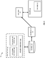
- FIG. 3 is a schematic diagram of an embodiment of a development platform 300 for creating and executing a flow plan.
- the development platform 300 may separate out the user experience in creating the action flow plan from the run-time considerations of storing and executing the run-time flow plan.
- the development platform 300 uses a service hub system 302 to create the action flow plan using database structures, and the flow engines 314 and 318 are configured to have no knowledge of the database structure of the action flow plans and/or actions designed with the service hub system 302.
- the flow engines 314 and 318 may execute a run-time version of the action flow plan, which in one embodiment are compiled JSON documents built via a flow plan builder API 312.
- a flow engine 318 can be implemented on a MID server 316 using the same engine code base as being executed on a server instance.
- the run-time flow is constructed from operations with data dependencies between each of the operations.
- the flow engines 314 and 318 may be able to execute the operation such that the data dependencies are met along with any explicitly execution order dependencies. The details of how any given operation performs or executes its functions are abstracted away from the flow engines 314 and 318.
- the service hub system 302 may implemented using a Java ® -based client device that would construct the active flow plan and request the flow engines 314 and/or 318 to run the active flow plan.
- the user could build a series of actions and variable bindings and chain them together into a flow plan. How the user constructs the action flow plan can be entirely up to the user.
- an action flow plan can be metadata driven or it can be hard-coded.
- development platform 300 constructs and generates the action flow plan, the user can choose to save for future execution, or simply pass the action flow plan to the flow engines 314 and/or 318 for immediate execution.
- service hub system 302 can also be generally referred to as and may be considered synonymous with the term "flow designer.”
- a user can create an action flow plan via the flow designer interface 306 by specifying one or more triggers for an action flow plan and one or more actions that follow in response to the triggers.
- a user may create an action flow plan for a financial enterprise operation that triggers when a specific incident report is created (e.g., a created report that customer lost credit card).
- the creation of the specific incident report results in the creation of a financial action (e.g., lookup credit card account information).
- the creation of the financial action can use some of the data from the triggering event, which in this example would be the creation of the specific incident report, as an input signature (e.g., name of credit card holder and credit card number) for the created action.
- the action flow plan could also include other financial actions (e.g., cancelling credit card) with other input signatures.
- the action designer user interface 304 allows the user to construct customizable actions within the action flow plan using action steps.
- Each action within the action flow plan can include one or more action steps.
- each action step includes a configured action step template that specifies the operation to perform, defines the input and output data signatures for the action step, and what data values to pass to other action steps in the action flow plan.
- the input signatures for the action step can be a fixed value, registered as an observer of one of a previous action step's output, left unset, or combinations thereof.
- the action step may provide the input signature to the operation to produce an output data signature.
- the action step can then be configured to pass the output data signature to one or more other actions steps within the same action and/or other actions within the action flow plan.
- FIG. 3 also depicts that the service hub system 302 includes a web service API 308, such as a REST API, to interface with a configuration management database (CMDB) that creates a data model 310 representative of the action flow plan.
- CMDB configuration management database
- the flow designer interface 306 and the action designer user interface 304 may call a web service API 308, which may also be part of the service hub 302, to drive a data model 310 for the action flow plan.
- the data model 310 acts as a database structure that defines the action flow plan as a user continuously modifies the action flow plan.
- the user via the flow designer interface 306 and/or the action designer user interface 304 can save the action flow plan for later execution or provide instructions to publish the action flow plan.
- flow plan builder API 312 can also be generally referred to as "flow plan builder.”
- the developmental platform 300 provides the flow plan builder API 312 to convert the action flow plan represented by data model 310 into a run-time flow plan, for example, a JSON document.
- the flow plan builder API 312 provides a structure to add action steps to actions and actions to the flow plan.
- Each element (e.g., action step or action) within the created flow plan has an input and output signature. Inputs can be fixed values (e.g., hard coded) or set to observe a previous element output.
- An example layout of an action flow plan and a run-time flow plan are shown and discussed in more detail in FIG. 4 .
- Action flow plans may not be executed by flow engines 314 and 318 until a user instructs a client device to publish the action flow plan.
- publishing the action flow plan causes the development platform 300 to activate the action flow plan by reading the data model 310 using a glide-flow-service, call the flow plan builder API 312 to convert (e.g., compile) the data model 310, and store the generated run-time flow plan.
- the run-time flow plan is stored as a JSON string in a trigger table.
- the specified type of trigger for the action flow plan may also determine what other records the compilation process creates to instantiate and execute an instance of the run-time flow plan.
- the flow engines 314 and 318 execute the run-time flow plan (e.g., JSON document) once one or more conditions or events occur that satisfy the trigger.
- the flow engine 314 and 318 annotates it run-time state information to determine whether operations within the run-time flow plan are ready to run. An operation within a run-time flow plan is ready to run when its input values are ready and the flow engine has completed any predecessor operations.
- the run-time flow plan when de-serialized from JSON, is composed of OpDatum objects that hold input values and output values, operation class references, execution state, application scope, and ancestor and predecessor operation references.
- the flow engines 314 and 318 execute the operations as they are ready. An operation within the run-time flow may be ready when all its input values report ready and the operations predecessors have completed.
- the flow engines 314 and 318 call the execute method of the operation class. This sets the specified application scope and then calls the abstract run method. As the various run methods update the output values, registered input values observers are automatically notified. If there are no exceptions thrown, the operation is marked as having been completed. This process continues while there are ready operations.
- the run-time flow plan serializes into a context record.
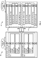
- FIG. 4 is an illustration that maps the relationship between an action flow plan 400 and a run-time flow plan 402.
- FIG. 4 's depiction of the action flow plan 400 is a graphical representation of a data model prior to compilation. Recall the action flow plan 400 can be created using a developmental platform's service hub system that drives the data model representation of the action flow plan 400.
- the action flow plan 400 may include a trigger component element 404 and a flow component element 408.
- the flow component element 408 includes a plurality of action component elements 412, where each action component element 412 includes action step component elements 414.
- the action component element 412 may be considered an abstraction boundary that is generally defined in domain terms and the action step component elements is typically defined in application platform based specific terms, such as a script and/or create, read, update and delete (CRUD) operations on a specific data structure.
- the trigger component element 404, action component elements 412 and action step component elements 414 can be customized, modified, and updated using the service hub system. For example, a user may select when the action flow plan 400 should execute by selecting and configuring the trigger component element 404.
- the service hub system is able link input values within an input signature 428 of a given component element (e.g., flow component element 408, action component elements 412, and action step component elements 414) with output values within an output signatures 426 of other component elements and/or input values of component element located within the given component element.
- the linking between the input values and output values create an observer and observable relationship between the different component elements. For example, input values for one or more action step elements 414 located within the given action component element 412 can observe a given action component element's 412 input values.
- the input signature of the given component element register could include input values that have fixed values (e.g., hard coded), are left unset, or combinations thereof.
- FIG. 4 depicts that the trigger component element 404 includes an output signature 426, and the flow component element 408, action component elements 412, and action step component elements 414 include both input signatures 428 and output signatures 426.
- the trigger component element's 404 output signature 426 links to the flow component element's 408 input signature 428.
- the flow component element's 408 input signature 428 then becomes action component element's 412a input signature 428, which then is linked to action step component element's 414a input signature 428.
- Action step component 414b's input signature 428 then observes action step component element's 414a output signature 426.
- Action step 414b's output signature 426 subsequently links to action 412a's output signature 426.
- Action component element's 412b input signature 428 then observes action component element's 412a output signature 426.
- the input signatures 428 and output signatures 426 for action step component element 414c's and 414d's located within action component element 412b follow a similar observer/observable relationship as described for action step component element 414a and 414b.
- Action component element's 412b output signature 426 is then linked to the flow component element's 408 output signature 426.
- a user may provide instructions to publish the action flow plan 400 via the service hub system.
- the developmental platform's flow builder API converts (e.g., compiles) the action flow plan 400 to generate a run-time flow plan 402.
- the flow builder API provides a structure to add action step components 414 to action component element 412 and action a component element to flow component element 408.
- the flow builder API coverts the action step component 414 into an OpDatum record in the run-time flow plan's 402 action 434.
- action component element's 412 operation plans are added to the flow operation 410.
- FIG. 4 illustrates the resulting run-time flow plan 402 after compiling the action flow plan 400.
- the run-time flow plan 402 includes a trigger operation 406 and flow plan operation 410.
- the trigger operation 406 can include a responder that executes flow plan operation 410 stored with the trigger operation 406.
- Examples of types of trigger operations 506 include a record watcher trigger created to execute flow plan operation 410 for a record that meets specific conditions, scheduled triggers created to flow plan operation 410 periodically or once at a specific time, and REST triggers created to execute the flow plan operation 410 in response to inbound REST requests.
- Other embodiments of the action flow plan 400 and corresponding run-time flow plan 402 can include other types of triggers.
- the flow plan operation 410 includes a serializable set of operations 416, 418, 420, 422, and 424, where each operation includes input signatures 430 and output signatures 432.
- the flow plan operation 410 includes a flow start directive operation 416 that contains the input signature 430 of the flow plan operation 410, which observes the trigger operation's output signature 432.
- the flow plan operation 410 includes a flow end directive operation 424 that hosts the output signature 432 for the flow plan operation 410.
- a flow engine that executes the flow plan operation 410 may minimize database operations within a CMDB to a read operation corresponding to flow start directive operation 416 and a write operation corresponding to the flow end directive operation 424. When executing the flow plan operation 410, the flow engine can avoid other database operations within the CMDB, such as managing a global state.
- Each action 434 likewise gets an action start directive operation 418 and action end directive operation 422.
- a user may map the input signatures 430 of the action component elements 412 from the flow component element 408 or from other action component elements 412.
- the flow start directive operation 416, action start directive operation 418, and/or end directive operations 422 provide a structure in the flow plan operation 410 for the mapping of input signatures 430.
- each action step operation 420 may become a single operation.
- the action step operation 420 may have its inputs values mapped from the action's 434 input signature, which is hosted on the action start directive operation 418, or from a predecessor action step operation 420.
- input values within input signatures 430 may reference output values found within output signatures 432.
- FIG. 4 illustrates specific embodiments of an action flow plan 400 and a run-time flow plan 402 that arranges actions (e.g., action component element 412A and action 434) in a linear sequence
- the disclosure is not limited to the specific embodiments illustrated in FIG. 3 .
- other embodiments of the action flow plan 400 and a run-time flow plan 402 could include branching, looping, and/or parallel execution semantics.
- the action flow plan 400 and a run-time flow plan 402 may be configured to include dynamic mutation operations that dynamically create actions and/or operations that execute repeatable operations over sets of data and/or while a condition state exists.
- action flow plan 400 and a run-time flow plan 402 may be configured to include conditional logic that optionally executes actions and/or operations based upon a condition state.
- conditional logic that optionally executes actions and/or operations based upon a condition state.
- FIG. 5 illustrates a serializable set of operations 502a-502c that corresponds to a portion of a run-time flow plan 500.
- operations 502a can correspond to an action start directive operation 418 and operations 502b and 502c correspond to action step operations 420.
- operations 502a-502c could correspond to action step operations 420.
- FIG. 5 depicts that the each operation 502a-502c in the run-time flow plan 500 has an input signature 504 and output signature 510.
- the input signature 504 includes input values 506a-506j and the output signatures 510 include output values 508a-508h.
- the input values 506a-506j and output values 508a-508h are linked together to implement a serializable, observer/observable relationship between the operations 502a-502c. As operations 502a-502c complete and populate their output values 508a-508h with data, the output values 508a-508h will notify all of its registered observer input values 506a-506j. When a flow engine queries the input values 506a-506j as to their status, the input values 506a-506j will report that they are not ready if the input values 506a-506j have not been notified of their value by their registered observable output values 508a-508h. If the input values 506a-506j have been notified, or are not observing anything, the input values 506a-506j report as ready.
- operation 502a may include an input signature 504a that includes four input values 506a-506d and an output signature 510a with three output values 508a-508c;
- operation 502b may include an input signature 504b that includes two input values 506e and 506f and an output signature 510b with two output values 508d and 508e;
- operation 502c may include an input signature 504c that includes four input values 506g-506j and an output signature 510c with three output values 508f-508h.
- operation 502a executes to produce output values 508a-508c.
- Input values 506e and 506f of operation 502b observes the output values 508a and 508b, respectively, and input values 506i and 506j of operation 502c observes the output values 508b and 508c, respectively.
- operation 502b's input values 506e and 506f are ready and operation 502b is then able to execute to produce the two output values 508d and 508e.
- the input values 506g and 506h from operation 502c observe the two output values 508d and 508e.
- operation 502b executes and notifies operation 502c that input values 506g and 506h are ready and operation 502a executes and notifies operation 502c input values 506i and 506j are ready, operation 502c executes to produce output values 508f-508h.
- FIG. 6 is a schematic diagram of another embodiment of a development platform 600 for creating and executing a flow plan.
- the flow designer 602, flow plan builder 604, and service hub data model 608 are similar to FIG. 3 's service hub system 302, flow plan builder API 312, and data model 310, respectively.
- the flow designer 602 can include one or more user interfaces for a user to customize, modify, and update an action flow plan.
- the flow designer 602 drives the service hub data model 608, which defines the action flow plan.
- the flow designer 602 may send the trigger operation information associated with the run-time flow plan to a trigger responder 606.
- the trigger responder 606 monitors whether a computing operation satisfies one or more conditions or events specified by the trigger operation information.
- the trigger responder 606 inserts a scheduled job for the run-time flow plan into a scheduler queue 610.
- the worker pool 612 may assign one or more existing worker threads for the flow engine 614 to execute the run-time flow plan.
- the flow engine 614 may use multiple worker threads to support execution of actions within the run-time flow plan.
- Having the trigger responder 606 insert a scheduled job within the scheduler queue 610 and subsequently assigning worker threads from worker pool 612 can minimize performance impact and disruption when executing the run-time flow plan.
- the different actions for the run-time flow plan may run asynchronously from a main thread, and thus not block the main thread when running long operations for the run-time flow plan.
- FIG. 6 illustrates that a flow engine 614 and a flow engine 616 can be implemented on both a customer instance and a MID server, respectively.
- the flow plan builder 604 For flow engine 616 to execute an action of a run-time flow plan on the MID server, the flow plan builder 604 generates a run-time flow plan that includes two action start directive operations and two action end directive operations.
- the action 434 instead of having the action 434 include a single set of an action start directive operation 418 and action end directive operation 422, the action 434 can instead include two pairs of action start directive operation 418 and action end directive operation 422.
- the second pair of action start directive operation 418 and action end directive operation 422 may be located between the first pair of action start directive operation 418 and action end directive operation 422.
- the flow engine 614 executes the first action start directive operation 418 within a run-time flow plan
- the flow engine 614 propagates inputs for the second action start directive operation's 418 input signature.
- the flow engine 614 can package all of the operations (e.g., action step operations) between the second action start directive operation 418 and action end directive operation 422 and forward the packaged operations to the External Communication Channel (ECC) queue 618.
- ECC External Communication Channel
- the ECC queue 618 then forwards the package operations as an ECC queue message to the MID server.
- the ECC queue 618 is a database table that is normally queried, updated, and inserted into by other computing system operating outside the customer instance. Each record in the ECC queue 618 may be a message, either from the customer instance (e.g., flow engine 614) to some other system or from the other system to the customer instance.
- the ECC queue 618 can act as a connection point (though not the only possible one) between the customer instance and other systems that integrate with it. As shown in FIG. 6 , the ECC queue also acts as the connection between the customer instance and the MID server. As such, although FIG. 6 illustrates that the flow engine 616 is located on the MID server, other embodiments could have the flow engine 616 located on another remote computing system.
- Flow engine 616 uses the received context records to updates the flow engine's 616 run-time state information and resume executing operations based on the received context records.
- flow engine 616 is done executing the run-time flow plan, either because the flow engine 616 has completed all operations or because it is waiting for external events, the run-time flow plan serializes to a context record.
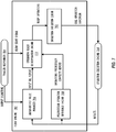
- FIG. 7 is a schematic diagram of an embodiment of a flow engine 702 for executing run-time flow plans.
- a trigger responder 704 which is similar to the trigger responder 606 shown in FIG. 6 , detects that one or more conditions or events satisfy a trigger for a run-time flow plan.
- the trigger responder 704 can send its output signature and a flow start signal to the flow engine 702.
- the flow engine's 702 input/output value manager 706 receives the output signature from the trigger responder 704 and the operation ready determination engine 710 receives the flow start signal.
- the input/output value manager 706 maps and manages the observer/observable relationship for the different operations within the run-time flow plan.
- the input/output value manager 706 may be aware of the input and output data signatures for each action step operation and what values to pass to other action step operation within the run-time flow plan. Based on the observer/observable relationship information, the input/output value manager 706 uses the output signature from the trigger responder 704 and/or other executed operations to generate an input value report that indicates which operations' input values are ready. As shown in FIG. 7 , the input/output value manager 706 provides the input value report to the operation ready determination engine 710 for further evaluation.
- the operation ready determination engine 710 begins to evaluate which operations are ready to run.
- FIG. 7 depicts that the operation ready determination engine 710 receives the input value report that indicates which operation's input values are ready and receives an operations predecessor complete report that indicates which predecessor operations have been completed. The operation ready determination engine 710 then uses the input value report and operations predecessor complete report to evaluate which operations are ready for execution. Rather than using a shared global state to determine the exact order of operation, the operation ready determination engine 710 is able to determine whether an operation is ready to run when its input values are ready and the flow engine has completed any predecessor operations. In other words, the flow engine 702 does not drive, coordinate, or manage when each operations should execute, but instead simplifies the evaluation process by detecting whether each operation's execution state have been met.
- FIG. 8 is a flowchart of an embodiment of method 800 that creates and executes a flow plan.
- Method 800 may create and execute flows using hardware, software, or both.
- FIGS. 3 as an example, method 800 may be implemented using the development platform 300, where the service hub 302 creates the action flow plan, the flow plan builder API 312 converts the action flow plan to a run-time flow plan, and the flow engine executes the run-time flow plan.
- method 800 may be implemented on a flow engine located in a customer instance.
- method 800 may be implemented on a two separate flow engines, one located on a customer instance and another located on another remote computing system, such as a MID server.
- FIG. 8 illustrates that the blocks of method 800 are implemented in a sequential operation, other embodiments of method 800 may have one or more blocks implemented in parallel operations.
- Method 800 may start at block 802 to create an action flow plan using one or more user interfaces. As discussed in FIGS. 3 and 6 , the user interfaces allow a user to create an action flow plan and drive a data model that represents the action flow plan. Method 800 may then move to block 804 to convert (e.g. compile) the action flow plan to a run-time flow plan. Method 800 may not convert the action flow plan to the fun-time flow plan until a user decides to publish the action flow plan. Once a user provides instructions via the user interfaces to publish the action flow plan, method 800 may use a flow plan builder for the conversion. From block 804, method 800 may continue to block 806 to determine that one or more conditions or events are satisfied for a trigger of the run-time flow plan.
- convert e.g. compile
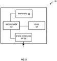
- FIG. 9 a block diagram illustrates a computing device 900 that may be used for implementing the techniques described herein in accordance with one or more embodiments (e.g., developmental platform 300, developmental platform 600, flow engine 314, flow engine 614, and method 800).
- the computing device 900 illustrated in FIG. 9 could represent a client device or a physical server device.
- the computing device 900 can include can also include one or more input/output devices, such as a network communication unit 908 that could include a wired communication component and/or a wireless communications component 290, which can be coupled to processing element 902.
- the network communication unit 208 can utilized any of a variety of standardized network protocols, such as Ethernet, TCP/IP, to name a few of many protocols, to effect communications between devices and comprise one or more transceiver(s) that utilize the Ethernet, power line communication (PLC), WiFi ® , and/or other communication methods.
- Ethernet Ethernet
- TCP/IP Transmission Control Protocol
- PLC power line communication
- WiFi ® Wireless Fidelity
- the computing system 900 includes a processing element 902 that contains one or more hardware processors, where each hardware processor may have a single or multiple processor cores.
- the processing element 902 may include at least one shared cache that store data (e.g., computing instructions) that are utilized by one or more other components of processing element 902.
- the shared cache may be locally cache data stored in a memory for faster access by components of the processing elements 902.
- the shared cache may include one or more mid-level caches, such as level 2 (L2), level 3 (L3), level 4 (L4), or other levels of cache, a last level cache (LLC), or combinations thereof.
- processors include, but are not limited to a central processing unit (CPU) a microprocessor.
- processing element 902 may also include one or more other types of hardware processing components, such as graphics processing units (GPU), application specific integrated circuits (ASICs), field-programmable gate arrays (FPGAs), and/or digital signal processors (DSPs).
- GPU graphics processing units
- ASICs application specific integrated circuits
- FPGAs field-programmable gate arrays
- DSPs digital signal processors
- FIG. 9 illustrates that memory 904 may be operatively coupled to processing element 902.
- Memory 904 may be a non-transitory medium configured to store various types of data.
- memory 904 may include one or more memory devices that comprise a non-volatile storage device and/or volatile memory.
- Volatile memory such as random access memory (RAM)
- RAM random access memory
- the non-volatile storage devices can include one or more disk drives, optical drives, solid-state drives (SSDs), tap drives, flash memory, read only memory (ROM), and/or any other type memory designed to maintain data for a duration time after a power loss or shut down operation.
- the non-volatile storage device may be used to store overflow data if allocated RAM is not large enough to hold all working data.
- the non-volatile storage device may also be used to store programs that are loaded into the RAM when such programs are selected for execution.
- the compiling process of the software program may transform program code written in a programming language to another computer language such that the processing element 902 is able to execute the programming code.
- the compiling process of the software program may generate an executable program that provides encoded instructions (e.g., machine code instructions) for processor 902 to accomplish specific, non-generic, particular computing functions.
- the encoded instructions may then be loaded as computer executable instructions or process steps to processing element 902 from storage (e.g., memory 904) and/or embedded within the processing element 902 (e.g., cache).
- Processing element 902 can execute the stored instructions or process steps in order to perform instructions or process steps to transform the computing device into a non-generic, particular, specially programmed machine or apparatus.
- Stored data e.g., data stored by a storage device, can be accessed by processing element 902 during the execution of computer executable instructions or process steps to instruct one or more components within the computing device 900.
- a user interface 910 can include a display, positional input device (such as a mouse, touchpad, touchscreen, or the like), keyboard, or other forms of user input and output devices.
- the user interface 910 can be coupled to processor element 902.
- Other output devices that permit a user to program or otherwise use the computing device can be provided in addition to or as an alternative to network communication unit 908.
- the display can be implemented in various ways, including by a liquid crystal display (LCD) or a cathode-ray tube (CRT) or light emitting diode (LED) display, such as an OLED display.
- LCD liquid crystal display
- CRT cathode-ray tube
- LED light emitting diode
- the computing device 900 may comprise other components well known in the art, such as sensors, powers sources, and/or analog-to-digital converters, not explicitly shown in FIG. 9 .
- FIG. 9 explanation of these other components well known in the art.
Landscapes
- Business, Economics & Management (AREA)
- Engineering & Computer Science (AREA)
- Human Resources & Organizations (AREA)
- Physics & Mathematics (AREA)
- General Physics & Mathematics (AREA)
- Economics (AREA)
- Entrepreneurship & Innovation (AREA)
- Strategic Management (AREA)
- Automation & Control Theory (AREA)
- Educational Administration (AREA)
- Theoretical Computer Science (AREA)
- Quality & Reliability (AREA)
- Tourism & Hospitality (AREA)
- Marketing (AREA)
- General Business, Economics & Management (AREA)
- Game Theory and Decision Science (AREA)
- Operations Research (AREA)
- Development Economics (AREA)
- Computer Networks & Wireless Communication (AREA)
- Signal Processing (AREA)
- Management, Administration, Business Operations System, And Electronic Commerce (AREA)
- Feedback Control In General (AREA)
- Combined Controls Of Internal Combustion Engines (AREA)
Claims (12)
- System, das Folgendes umfasst:einen nicht flüchtigen Speicher (904); undeinen oder mehrere Hardware-Prozessoren (902), die konfiguriert sind, um Anweisungen aus dem nicht flüchtigen Speicher (904) zu lesen, um das System zu Folgendem zu veranlassen:Erhalten eines Laufzeitflussplans (402), der einen Auslöser (406), einen ersten Ablauf (416, 418, 420, 422) und einen zweiten Ablauf (418, 420, 422, 424) umfasst, wobei der erste Ablauf (416, 418, 420, 422) dem zweiten Ablauf (418, 420, 422, 424) innerhalb des Laufzeitflussplans (402) vorangeht, und ein oder mehrere Eingabewerte (430) des zweiten Ablaufs (416, 418, 420, 422) mit dem ersten Ablauf (416, 418, 420, 422) verknüpft sind;Bestimmen, ob eine oder mehrere Bedingungen des Auslösers (406) erfüllt sind;Ausführen des ersten Ablaufs (416, 418, 420, 422) basierend wenigstens auf der Bestimmung, dass die eine oder die mehreren Bedingungen des Auslösers (406) erfüllt sind;Überwachen, ob der zweite Ablauf (418, 420, 422, 424) für die Ausführung bereit ist, basierend wenigstens auf Folgendem:Bestimmen, ob der eine oder die mehreren Eingabewerte (430) des zweiten Ablaufs (418, 420, 422, 424) bereit sind, wobei der eine oder die mehreren Eingabewerte (430) bereit sind, nachdem der erste Ablauf (416, 418, 420, 422) ausgeführt wurde; undBestimmen, ob der zweite Ablauf (418, 420, 422, 424) zu viele Rechenressourcen erfordern würde:Übertragen des zweiten Ablaufs (418, 420, 422, 424) und des einen oder der mehreren Eingabewerte (430) an einen Verwaltungs-, Instrumentierungs- und Ermittlungs(management, instrumentation, and discovery - MID)-Server (106) über eine Warteschlange eines externen Kommunikationskanals (external communication channel - ECC) (618) als Reaktion auf das Bestimmen, dass der eine oder die mehreren Eingabewerte (430) bereit sind und dass der zweite Ablauf (418, 420, 422, 424) zu viele Rechenressourcen erfordern würde, wobei der MID-Server (106) konfiguriert ist, um den zweiten Ablauf (418, 420, 422, 424) als Reaktion auf ein Empfangen des zweiten Ablaufs (418, 420, 422, 424) und des einen oder der mehreren Eingabewerte (430) auszuführen; undEmpfangen eines oder mehrerer Ausgabewerte (432), die dem zweiten Ablauf (418, 420, 422, 424) zugehörig sind, von dem MID-Server (106) über die ECC-Warteschlange (618).
- System nach Anspruch 1, wobei die Anweisungen das System zu Folgendem veranlassen:Empfangen eines Aktionsflussplans (400), der mehrere Aktionen (412) umfasst, wobei jede Aktion (412) einen Aktionsschritt (414) umfasst; undUmwandeln des Aktionsflussplans (400) in den Laufzeitflussplan (402), wobei jeder Aktionsschritt (414) jeder Aktion (412) in einen Aktionsschrittablauf (420) umgewandelt wird.
- System nach Anspruch 2, wobei der erste Ablauf (416, 418, 420, 422) ein Aktionsschrittablauf (420) ist.
- System nach Anspruch 2, wobei der Aktionsflussplan (400) als ein Datenmodell (310) innerhalb einer Konfigurationsverwaltungsdatenbank (212) dargestellt wird.
- System nach Anspruch 1, wobei ein globaler Zustand nicht verwendet wird, um zu überwachen, ob der zweite Ablauf (418, 420, 422, 424) für die Ausführung bereit ist.
- System nach Anspruch 1, wobei die Anweisungen das System veranlassen, zu überwachen, ob der zweite Ablauf (418, 420, 422, 424) für die Ausführung bereit ist, basierend wenigstens auf dem Bestimmen, ob der eine oder die mehreren Eingabewerte (430) des zweiten Ablaufs (418, 420, 422, 424) bereit sind, dem Bestimmen, ob der zweite Ablauf (418, 420, 422, 424) zu viele Rechenressourcen erfordern würde, und dem Bestimmen, ob ein dritter Ablauf innerhalb des Laufzeitflussplans (402) die Ausführung abgeschlossen hat.
- System nach Anspruch 1, wobei der erste Ablauf (416, 418, 420, 422) ein erster Aktionsstart-Richtlinienablauf (418) ist und der zweite Ablauf (418, 420, 422, 424) ein zweiter Aktionsstart-Richtlinienablauf (418) ist.
- System nach Anspruch 1, wobei der Laufzeitflussplan (402) ferner einen dritten Ablauf (420, 422, 424) umfasst, der mit dem einen oder den mehreren Ausgabewerten (432) verknüpft ist, die dem zweiten Ablauf (418, 420, 422, 424) zugehörig sind.
- Verfahren, das Folgendes umfasst:Erhalten eines Laufzeitflussplans (402), der einen Auslöser (406), einen ersten Ablauf (416, 418, 420, 422) und einen zweiten Ablauf (418, 420, 422, 424) umfasst, wobei der erste Ablauf (416, 418, 420, 422) dem zweiten Ablauf (418, 420, 422, 424) innerhalb des Laufzeitflussplans (402) vorangeht, und ein oder mehrere Eingabewerte (430) des zweiten Ablaufs (418, 420, 422, 424) mit dem ersten Ablauf (416, 418, 420, 422) verknüpft sind;Bestimmen, ob eine oder mehrere Bedingungen des Auslösers (406) erfüllt sind;Ausführen des ersten Ablaufs (416, 418, 420, 422) basierend wenigstens auf der Bestimmung, dass die eine oder die mehreren Bedingungen des Auslösers (406) erfüllt sind;Überwachen, ob der zweite Ablauf für die Ausführung bereit ist, basierend wenigstens auf Folgendem:Bestimmen, ob der eine oder die mehreren Eingabewerte (430) des zweiten Ablaufs (418, 420, 422, 424) bereit sind, wobei der eine oder die mehreren Eingabewerte (430) bereit sind, nachdem der erste Ablauf (416, 418, 420, 422) ausgeführt wurde; undBestimmen, ob der zweite Ablauf (418, 420, 422, 424) zu viele Rechenressourcen erfordern würde:Übertragen des zweiten Ablaufs (418, 420, 422, 424) und des einen oder der mehreren Eingabewerte (430) an einen Verwaltungs-, Instrumentierungs- und Ermittlungs(MID)-Server (106) über eine Warteschlange eines externen Kommunikationskanals (ECC) (618) als Reaktion auf das Bestimmen, dass der eine oder die mehreren Eingabewerte (430) bereit sind und dass der zweite Ablauf (418, 420, 422, 424) zu viele Rechenressourcen erfordern würde, wobei der MID-Server (106) konfiguriert ist, um den zweiten Ablauf als Reaktion auf das Empfangen des zweiten Ablaufs (418, 420, 422, 424) und des einen oder der mehreren Eingabewerte (430) auszuführen; undEmpfangen des einen oder der mehreren Ausgabewerte (432), die dem zweiten Ablauf (418, 420, 422, 424) zugehörig sind, von dem MID-Server (106) über die ECC-Warteschlange (618).
- Verfahren nach Anspruch 9, das ferner Folgendes umfasst:Empfangen eines Aktionsflussplans (400), der mehrere Aktionen (412) umfasst, wobei jede Aktion (412) einen Aktionsschritt (414) umfasst; undUmwandeln des Aktionsflussplans (400) in den Laufzeitflussplan (402), wobei jeder Aktionsschritt (414) jeder Aktion (412) in einen Aktionsschrittablauf (420) umgewandelt wird.
- Verfahren nach Anspruch 9, wobei der erste Ablauf (416, 418, 420, 422) ein erster Aktionsstart-Richtlinienablauf (418) ist und der zweite Ablauf (418, 420, 422, 424) ein zweiter Aktionsstart-Richtlinienablauf (418) ist.
- Verfahren nach Anspruch 9, wobei der Laufzeitflussplan (402) einen dritten Ablauf (420, 422, 424) umfasst, der mit dem einen oder den mehreren Ausgabewerten (432) verknüpft ist, die dem zweiten Ablauf (418, 420, 422, 424) zugehörig sind.
Applications Claiming Priority (1)
| Application Number | Priority Date | Filing Date | Title |
|---|---|---|---|
| US15/587,075 US10534337B2 (en) | 2017-05-04 | 2017-05-04 | Flow engine for building automated flows within a cloud based developmental platform |
Publications (2)
| Publication Number | Publication Date |
|---|---|
| EP3399476A1 EP3399476A1 (de) | 2018-11-07 |
| EP3399476B1 true EP3399476B1 (de) | 2022-01-12 |
Family
ID=60143500
Family Applications (1)
| Application Number | Title | Priority Date | Filing Date |
|---|---|---|---|
| EP17194240.2A Active EP3399476B1 (de) | 2017-05-04 | 2017-09-29 | Strömungsmaschine zum aufbauen von automatisierten abläufen innerhalb einer cloud-basierten entwicklungsplattform |
Country Status (4)
| Country | Link |
|---|---|
| US (2) | US10534337B2 (de) |
| EP (1) | EP3399476B1 (de) |
| AU (1) | AU2017236024B2 (de) |
| CA (2) | CA3032515C (de) |
Families Citing this family (11)
| Publication number | Priority date | Publication date | Assignee | Title |
|---|---|---|---|---|
| US10534337B2 (en) | 2017-05-04 | 2020-01-14 | Servicenow, Inc. | Flow engine for building automated flows within a cloud based developmental platform |
| CN110008034A (zh) * | 2018-11-22 | 2019-07-12 | 阿里巴巴集团控股有限公司 | 任务自动化执行方法、装置、电子设备及存储介质 |
| US10848379B2 (en) * | 2019-01-30 | 2020-11-24 | Hewlett Packard Enterprise Development Lp | Configuration options for cloud environments |
| US10929107B2 (en) | 2019-03-19 | 2021-02-23 | Servicenow, Inc. | Workflow support for dynamic action output |
| US10452360B1 (en) | 2019-03-19 | 2019-10-22 | Servicenow, Inc. | Workflow support for dynamic action input |
| US11100075B2 (en) * | 2019-03-19 | 2021-08-24 | Servicenow, Inc. | Graphical user interfaces for incorporating complex data objects into a workflow |
| US10678418B1 (en) | 2019-03-19 | 2020-06-09 | Servicenow, Inc. | Graphical user interfaces for defining complex data objects |
| US11258865B2 (en) | 2019-03-28 | 2022-02-22 | Servicenow, Inc. | Automated integration with cloud-based services |
| US11743350B2 (en) | 2021-01-07 | 2023-08-29 | The Toronto-Dominion Bank | System and method for integrating external services into process workflow environments |
| US11561827B2 (en) | 2021-01-07 | 2023-01-24 | The Toronto-Dominion Bank | System and method for executing a dynamic routing service |
| US11449312B2 (en) | 2021-01-07 | 2022-09-20 | The Toronto-Dominion Bank | System and method for executing a process workflow |
Family Cites Families (35)
| Publication number | Priority date | Publication date | Assignee | Title |
|---|---|---|---|---|
| US6321229B1 (en) | 1999-02-26 | 2001-11-20 | Hewlett-Packard Company | Method and apparatus for using an information model to organize an information repository into a hierarchy of information |
| US6678887B1 (en) | 2000-07-11 | 2004-01-13 | Networks Associates Technology, Inc. | Customizing business logic and data sources by modifying methods defined within an API |
| US7350209B2 (en) | 2001-06-29 | 2008-03-25 | Bmc Software | System and method for application performance management |
| US20030187495A1 (en) | 2002-04-01 | 2003-10-02 | Cully Edward H. | Endoluminal devices, embolic filters, methods of manufacture and use |
| US7020706B2 (en) | 2002-06-17 | 2006-03-28 | Bmc Software, Inc. | Method and system for automatically updating multiple servers |
| US7194728B1 (en) | 2002-11-18 | 2007-03-20 | Bmc Software, Inc. | System and method for packaging updates |
| US7925981B2 (en) | 2003-05-14 | 2011-04-12 | Hewlett-Packard Development Company, L.P. | Systems and methods for managing web services via a framework of interfaces |
| US20070017410A1 (en) * | 2003-10-14 | 2007-01-25 | Sky Train Corporation | Overhead Suspended Transportation System and Method |
| US7133884B1 (en) | 2003-11-26 | 2006-11-07 | Bmc Software, Inc. | Unobtrusive point-in-time consistent copies |
| US20060074735A1 (en) | 2004-10-01 | 2006-04-06 | Microsoft Corporation | Ink-enabled workflow authoring |
| GB0427133D0 (en) * | 2004-12-10 | 2005-01-12 | British Telecomm | Workflow scheduler |
| US8612408B2 (en) | 2004-12-21 | 2013-12-17 | Bmc Software, Inc. | System and method for business service management |
| US7716353B2 (en) | 2005-12-21 | 2010-05-11 | Bmc Software, Inc. | Web services availability cache |
| US7610512B2 (en) | 2006-01-06 | 2009-10-27 | Hewlett-Packard Development Company, L.P. | System and method for automated and assisted resolution of it incidents |
| US8555287B2 (en) | 2006-08-31 | 2013-10-08 | Bmc Software, Inc. | Automated capacity provisioning method using historical performance data |
| US8234623B2 (en) * | 2006-09-11 | 2012-07-31 | The Mathworks, Inc. | System and method for using stream objects to perform stream processing in a text-based computing environment |
| US10411975B2 (en) | 2013-03-15 | 2019-09-10 | Csc Agility Platform, Inc. | System and method for a cloud computing abstraction with multi-tier deployment policy |
| US8646093B2 (en) | 2009-03-31 | 2014-02-04 | Bmc Software, Inc. | Method and system for configuration management database software license compliance |
| US9122536B2 (en) | 2009-12-30 | 2015-09-01 | Bmc Software, Inc. | Automating application provisioning for heterogeneous datacenter environments |
| US8832652B2 (en) | 2010-03-26 | 2014-09-09 | Bmc Software, Inc. | Method for customizing software applications |
| US8402127B2 (en) | 2010-06-28 | 2013-03-19 | Bmc Software, Inc. | System and method for offering virtual private clouds within a public cloud environment |
| CN104335179B (zh) | 2012-02-13 | 2018-01-23 | 甲骨文国际公司 | 云计算环境中的过程的协调 |
| US8914768B2 (en) | 2012-03-28 | 2014-12-16 | Bmc Software, Inc. | Automated blueprint assembly for assembling an application |
| EP2645196B1 (de) * | 2012-03-30 | 2018-12-12 | The Boeing Company | Netzwerk aus unbemannten Fahrzeugen |
| US9122552B2 (en) | 2012-06-29 | 2015-09-01 | Bmc Software, Inc. | Hybrid cloud infrastructures |
| US9645833B2 (en) | 2012-12-31 | 2017-05-09 | Bmc Software, Inc. | Additive independent object modification |
| US9317327B2 (en) | 2013-02-28 | 2016-04-19 | Bmc Software, Inc. | Computing infrastructure planning |
| US9098322B2 (en) | 2013-03-15 | 2015-08-04 | Bmc Software, Inc. | Managing a server template |
| US9654473B2 (en) | 2013-06-28 | 2017-05-16 | Bmc Software, Inc. | Authentication proxy agent |
| EP3047453A1 (de) * | 2013-09-16 | 2016-07-27 | VII Network Inc. | Internet- und mobilplattform zur verbindung von workflow-management und einer asynchronen videozusammenarbeit zur gesundheitspflege |
| US10198490B2 (en) | 2014-01-06 | 2019-02-05 | Salesforce.Com, Inc. | Systems and methods for interactively configuring multiple conditions and multiple actions in a workflow application |
| US20150378784A1 (en) * | 2014-06-27 | 2015-12-31 | International Business Machines Corporation | Work flow level job input/output |
| US9535737B2 (en) | 2015-01-30 | 2017-01-03 | Bladelogic, Inc. | Dynamic virtual port provisioning |
| US10684890B2 (en) | 2015-05-08 | 2020-06-16 | Accenture Global Services Limited | Network deployment for cellular, backhaul, fiber optic and other network infrastructure |
| US10534337B2 (en) | 2017-05-04 | 2020-01-14 | Servicenow, Inc. | Flow engine for building automated flows within a cloud based developmental platform |
-
2017
- 2017-05-04 US US15/587,075 patent/US10534337B2/en active Active
- 2017-09-29 CA CA3032515A patent/CA3032515C/en active Active
- 2017-09-29 EP EP17194240.2A patent/EP3399476B1/de active Active
- 2017-09-29 CA CA2980914A patent/CA2980914C/en active Active
- 2017-09-29 AU AU2017236024A patent/AU2017236024B2/en active Active
-
2019
- 2019-12-16 US US16/716,174 patent/US11137732B2/en active Active
Non-Patent Citations (1)
| Title |
|---|
| None * |
Also Published As
| Publication number | Publication date |
|---|---|
| US11137732B2 (en) | 2021-10-05 |
| US20200209823A1 (en) | 2020-07-02 |
| CA3032515A1 (en) | 2018-11-04 |
| US10534337B2 (en) | 2020-01-14 |
| CA3032515C (en) | 2023-01-03 |
| CA2980914A1 (en) | 2018-11-04 |
| CA2980914C (en) | 2022-10-04 |
| AU2017236024B2 (en) | 2019-09-12 |
| EP3399476A1 (de) | 2018-11-07 |
| AU2017236024A1 (en) | 2018-11-22 |
| US20180321654A1 (en) | 2018-11-08 |
Similar Documents
| Publication | Publication Date | Title |
|---|---|---|
| EP3399476B1 (de) | Strömungsmaschine zum aufbauen von automatisierten abläufen innerhalb einer cloud-basierten entwicklungsplattform | |
| AU2019232804B2 (en) | Decision tables and flow engine for building automated flows within a cloud based development platform | |
| US10956013B2 (en) | User interface for automated flows within a cloud based developmental platform | |
| US11294711B2 (en) | Wait a duration timer action and flow engine for building automated flows within a cloud based development platform | |
| CA3003773C (en) | User interface for automated flows within a cloud based developmental platform | |
| US10101972B1 (en) | Data modelling and flow engine for building automated flows within a cloud based developmental platform | |
| US12554554B2 (en) | Management instrumentation and discovery (MID) server support for executing automated flows within a cloud based system | |
| CA3017085C (en) | Data modelling and flow engine for building automated flows within a cloud based developmental platform | |
| US11726796B2 (en) | Platform-based enterprise technology service portfolio management | |
| US10824642B2 (en) | Data synchronization architecture | |
| CN116414518A (zh) | Kubernetes上的大数据的数据局部性 | |
| EP3624027A1 (de) | Entscheidungstabellen und ablauf-maschine zum erstellen von automatisierten abläufen innerhalb einer cloud-basierten entwicklungsplattform | |
| US10997002B2 (en) | Quick actions | |
| Weissman et al. | Azure Arc-Enabled Data Services | |
| CA3003625C (en) | Capability based planning |
Legal Events
| Date | Code | Title | Description |
|---|---|---|---|
| PUAI | Public reference made under article 153(3) epc to a published international application that has entered the european phase |
Free format text: ORIGINAL CODE: 0009012 |
|
| STAA | Information on the status of an ep patent application or granted ep patent |
Free format text: STATUS: THE APPLICATION HAS BEEN PUBLISHED |
|
| AK | Designated contracting states |
Kind code of ref document: A1 Designated state(s): AL AT BE BG CH CY CZ DE DK EE ES FI FR GB GR HR HU IE IS IT LI LT LU LV MC MK MT NL NO PL PT RO RS SE SI SK SM TR |
|
| AX | Request for extension of the european patent |
Extension state: BA ME |
|
| STAA | Information on the status of an ep patent application or granted ep patent |
Free format text: STATUS: REQUEST FOR EXAMINATION WAS MADE |
|
| 17P | Request for examination filed |
Effective date: 20190503 |
|
| RBV | Designated contracting states (corrected) |
Designated state(s): AL AT BE BG CH CY CZ DE DK EE ES FI FR GB GR HR HU IE IS IT LI LT LU LV MC MK MT NL NO PL PT RO RS SE SI SK SM TR |
|
| STAA | Information on the status of an ep patent application or granted ep patent |
Free format text: STATUS: EXAMINATION IS IN PROGRESS |
|
| 17Q | First examination report despatched |
Effective date: 20190920 |
|
| RAP1 | Party data changed (applicant data changed or rights of an application transferred) |
Owner name: SERVICENOW, INC. |
|
| GRAP | Despatch of communication of intention to grant a patent |
Free format text: ORIGINAL CODE: EPIDOSNIGR1 |
|
| STAA | Information on the status of an ep patent application or granted ep patent |
Free format text: STATUS: GRANT OF PATENT IS INTENDED |
|
| INTG | Intention to grant announced |
Effective date: 20210722 |
|
| GRAS | Grant fee paid |
Free format text: ORIGINAL CODE: EPIDOSNIGR3 |
|
| GRAA | (expected) grant |
Free format text: ORIGINAL CODE: 0009210 |
|
| STAA | Information on the status of an ep patent application or granted ep patent |
Free format text: STATUS: THE PATENT HAS BEEN GRANTED |
|
| AK | Designated contracting states |
Kind code of ref document: B1 Designated state(s): AL AT BE BG CH CY CZ DE DK EE ES FI FR GB GR HR HU IE IS IT LI LT LU LV MC MK MT NL NO PL PT RO RS SE SI SK SM TR |
|
| REG | Reference to a national code |
Ref country code: GB Ref legal event code: FG4D |
|
| REG | Reference to a national code |
Ref country code: CH Ref legal event code: EP |
|
| REG | Reference to a national code |
Ref country code: DE Ref legal event code: R096 Ref document number: 602017052202 Country of ref document: DE |
|
| REG | Reference to a national code |
Ref country code: IE Ref legal event code: FG4D |
|
| REG | Reference to a national code |
Ref country code: AT Ref legal event code: REF Ref document number: 1462871 Country of ref document: AT Kind code of ref document: T Effective date: 20220215 |
|
| REG | Reference to a national code |
Ref country code: NL Ref legal event code: FP |
|
| REG | Reference to a national code |
Ref country code: LT Ref legal event code: MG9D |
|
| REG | Reference to a national code |
Ref country code: AT Ref legal event code: MK05 Ref document number: 1462871 Country of ref document: AT Kind code of ref document: T Effective date: 20220112 |
|
| PG25 | Lapsed in a contracting state [announced via postgrant information from national office to epo] |
Ref country code: SE Free format text: LAPSE BECAUSE OF FAILURE TO SUBMIT A TRANSLATION OF THE DESCRIPTION OR TO PAY THE FEE WITHIN THE PRESCRIBED TIME-LIMIT Effective date: 20220112 Ref country code: RS Free format text: LAPSE BECAUSE OF FAILURE TO SUBMIT A TRANSLATION OF THE DESCRIPTION OR TO PAY THE FEE WITHIN THE PRESCRIBED TIME-LIMIT Effective date: 20220112 Ref country code: PT Free format text: LAPSE BECAUSE OF FAILURE TO SUBMIT A TRANSLATION OF THE DESCRIPTION OR TO PAY THE FEE WITHIN THE PRESCRIBED TIME-LIMIT Effective date: 20220512 Ref country code: NO Free format text: LAPSE BECAUSE OF FAILURE TO SUBMIT A TRANSLATION OF THE DESCRIPTION OR TO PAY THE FEE WITHIN THE PRESCRIBED TIME-LIMIT Effective date: 20220412 Ref country code: LT Free format text: LAPSE BECAUSE OF FAILURE TO SUBMIT A TRANSLATION OF THE DESCRIPTION OR TO PAY THE FEE WITHIN THE PRESCRIBED TIME-LIMIT Effective date: 20220112 Ref country code: HR Free format text: LAPSE BECAUSE OF FAILURE TO SUBMIT A TRANSLATION OF THE DESCRIPTION OR TO PAY THE FEE WITHIN THE PRESCRIBED TIME-LIMIT Effective date: 20220112 Ref country code: ES Free format text: LAPSE BECAUSE OF FAILURE TO SUBMIT A TRANSLATION OF THE DESCRIPTION OR TO PAY THE FEE WITHIN THE PRESCRIBED TIME-LIMIT Effective date: 20220112 Ref country code: BG Free format text: LAPSE BECAUSE OF FAILURE TO SUBMIT A TRANSLATION OF THE DESCRIPTION OR TO PAY THE FEE WITHIN THE PRESCRIBED TIME-LIMIT Effective date: 20220412 |
|
| PG25 | Lapsed in a contracting state [announced via postgrant information from national office to epo] |
Ref country code: PL Free format text: LAPSE BECAUSE OF FAILURE TO SUBMIT A TRANSLATION OF THE DESCRIPTION OR TO PAY THE FEE WITHIN THE PRESCRIBED TIME-LIMIT Effective date: 20220112 Ref country code: LV Free format text: LAPSE BECAUSE OF FAILURE TO SUBMIT A TRANSLATION OF THE DESCRIPTION OR TO PAY THE FEE WITHIN THE PRESCRIBED TIME-LIMIT Effective date: 20220112 Ref country code: GR Free format text: LAPSE BECAUSE OF FAILURE TO SUBMIT A TRANSLATION OF THE DESCRIPTION OR TO PAY THE FEE WITHIN THE PRESCRIBED TIME-LIMIT Effective date: 20220413 Ref country code: FI Free format text: LAPSE BECAUSE OF FAILURE TO SUBMIT A TRANSLATION OF THE DESCRIPTION OR TO PAY THE FEE WITHIN THE PRESCRIBED TIME-LIMIT Effective date: 20220112 Ref country code: AT Free format text: LAPSE BECAUSE OF FAILURE TO SUBMIT A TRANSLATION OF THE DESCRIPTION OR TO PAY THE FEE WITHIN THE PRESCRIBED TIME-LIMIT Effective date: 20220112 |
|
| PG25 | Lapsed in a contracting state [announced via postgrant information from national office to epo] |
Ref country code: IS Free format text: LAPSE BECAUSE OF FAILURE TO SUBMIT A TRANSLATION OF THE DESCRIPTION OR TO PAY THE FEE WITHIN THE PRESCRIBED TIME-LIMIT Effective date: 20220512 |
|
| REG | Reference to a national code |
Ref country code: DE Ref legal event code: R097 Ref document number: 602017052202 Country of ref document: DE |
|
| PG25 | Lapsed in a contracting state [announced via postgrant information from national office to epo] |
Ref country code: SM Free format text: LAPSE BECAUSE OF FAILURE TO SUBMIT A TRANSLATION OF THE DESCRIPTION OR TO PAY THE FEE WITHIN THE PRESCRIBED TIME-LIMIT Effective date: 20220112 Ref country code: SK Free format text: LAPSE BECAUSE OF FAILURE TO SUBMIT A TRANSLATION OF THE DESCRIPTION OR TO PAY THE FEE WITHIN THE PRESCRIBED TIME-LIMIT Effective date: 20220112 Ref country code: RO Free format text: LAPSE BECAUSE OF FAILURE TO SUBMIT A TRANSLATION OF THE DESCRIPTION OR TO PAY THE FEE WITHIN THE PRESCRIBED TIME-LIMIT Effective date: 20220112 Ref country code: EE Free format text: LAPSE BECAUSE OF FAILURE TO SUBMIT A TRANSLATION OF THE DESCRIPTION OR TO PAY THE FEE WITHIN THE PRESCRIBED TIME-LIMIT Effective date: 20220112 Ref country code: DK Free format text: LAPSE BECAUSE OF FAILURE TO SUBMIT A TRANSLATION OF THE DESCRIPTION OR TO PAY THE FEE WITHIN THE PRESCRIBED TIME-LIMIT Effective date: 20220112 Ref country code: CZ Free format text: LAPSE BECAUSE OF FAILURE TO SUBMIT A TRANSLATION OF THE DESCRIPTION OR TO PAY THE FEE WITHIN THE PRESCRIBED TIME-LIMIT Effective date: 20220112 |
|
| PLBE | No opposition filed within time limit |
Free format text: ORIGINAL CODE: 0009261 |
|
| STAA | Information on the status of an ep patent application or granted ep patent |
Free format text: STATUS: NO OPPOSITION FILED WITHIN TIME LIMIT |
|
| PG25 | Lapsed in a contracting state [announced via postgrant information from national office to epo] |
Ref country code: AL Free format text: LAPSE BECAUSE OF FAILURE TO SUBMIT A TRANSLATION OF THE DESCRIPTION OR TO PAY THE FEE WITHIN THE PRESCRIBED TIME-LIMIT Effective date: 20220112 |
|
| 26N | No opposition filed |
Effective date: 20221013 |
|
| PG25 | Lapsed in a contracting state [announced via postgrant information from national office to epo] |
Ref country code: SI Free format text: LAPSE BECAUSE OF FAILURE TO SUBMIT A TRANSLATION OF THE DESCRIPTION OR TO PAY THE FEE WITHIN THE PRESCRIBED TIME-LIMIT Effective date: 20220112 |
|
| PG25 | Lapsed in a contracting state [announced via postgrant information from national office to epo] |
Ref country code: MC Free format text: LAPSE BECAUSE OF FAILURE TO SUBMIT A TRANSLATION OF THE DESCRIPTION OR TO PAY THE FEE WITHIN THE PRESCRIBED TIME-LIMIT Effective date: 20220112 |
|
| REG | Reference to a national code |
Ref country code: CH Ref legal event code: PL |
|
| REG | Reference to a national code |
Ref country code: BE Ref legal event code: MM Effective date: 20220930 |
|
| PG25 | Lapsed in a contracting state [announced via postgrant information from national office to epo] |
Ref country code: LU Free format text: LAPSE BECAUSE OF NON-PAYMENT OF DUE FEES Effective date: 20220929 |
|
| PG25 | Lapsed in a contracting state [announced via postgrant information from national office to epo] |
Ref country code: LI Free format text: LAPSE BECAUSE OF NON-PAYMENT OF DUE FEES Effective date: 20220930 Ref country code: IT Free format text: LAPSE BECAUSE OF FAILURE TO SUBMIT A TRANSLATION OF THE DESCRIPTION OR TO PAY THE FEE WITHIN THE PRESCRIBED TIME-LIMIT Effective date: 20220112 Ref country code: IE Free format text: LAPSE BECAUSE OF NON-PAYMENT OF DUE FEES Effective date: 20220929 Ref country code: CH Free format text: LAPSE BECAUSE OF NON-PAYMENT OF DUE FEES Effective date: 20220930 |
|
| PG25 | Lapsed in a contracting state [announced via postgrant information from national office to epo] |
Ref country code: BE Free format text: LAPSE BECAUSE OF NON-PAYMENT OF DUE FEES Effective date: 20220930 |
|
| PG25 | Lapsed in a contracting state [announced via postgrant information from national office to epo] |
Ref country code: HU Free format text: LAPSE BECAUSE OF FAILURE TO SUBMIT A TRANSLATION OF THE DESCRIPTION OR TO PAY THE FEE WITHIN THE PRESCRIBED TIME-LIMIT; INVALID AB INITIO Effective date: 20170929 |
|
| PG25 | Lapsed in a contracting state [announced via postgrant information from national office to epo] |
Ref country code: CY Free format text: LAPSE BECAUSE OF FAILURE TO SUBMIT A TRANSLATION OF THE DESCRIPTION OR TO PAY THE FEE WITHIN THE PRESCRIBED TIME-LIMIT Effective date: 20220112 |
|
| PG25 | Lapsed in a contracting state [announced via postgrant information from national office to epo] |
Ref country code: MK Free format text: LAPSE BECAUSE OF FAILURE TO SUBMIT A TRANSLATION OF THE DESCRIPTION OR TO PAY THE FEE WITHIN THE PRESCRIBED TIME-LIMIT Effective date: 20220112 |
|
| PG25 | Lapsed in a contracting state [announced via postgrant information from national office to epo] |
Ref country code: MT Free format text: LAPSE BECAUSE OF FAILURE TO SUBMIT A TRANSLATION OF THE DESCRIPTION OR TO PAY THE FEE WITHIN THE PRESCRIBED TIME-LIMIT Effective date: 20220112 |
|
| PGFP | Annual fee paid to national office [announced via postgrant information from national office to epo] |
Ref country code: DE Payment date: 20250926 Year of fee payment: 9 |
|
| PGFP | Annual fee paid to national office [announced via postgrant information from national office to epo] |
Ref country code: NL Payment date: 20250925 Year of fee payment: 9 |
|
| PGFP | Annual fee paid to national office [announced via postgrant information from national office to epo] |
Ref country code: GB Payment date: 20250923 Year of fee payment: 9 |
|
| PGFP | Annual fee paid to national office [announced via postgrant information from national office to epo] |
Ref country code: FR Payment date: 20250925 Year of fee payment: 9 |
|
| PG25 | Lapsed in a contracting state [announced via postgrant information from national office to epo] |
Ref country code: TR Free format text: LAPSE BECAUSE OF FAILURE TO SUBMIT A TRANSLATION OF THE DESCRIPTION OR TO PAY THE FEE WITHIN THE PRESCRIBED TIME-LIMIT Effective date: 20220112 |