EP3399346A1 - Normierungskristalleffizienzschätzung für die kontinuierliche bewegungsbetterfassung - Google Patents
Normierungskristalleffizienzschätzung für die kontinuierliche bewegungsbetterfassung Download PDFInfo
- Publication number
- EP3399346A1 EP3399346A1 EP18170350.5A EP18170350A EP3399346A1 EP 3399346 A1 EP3399346 A1 EP 3399346A1 EP 18170350 A EP18170350 A EP 18170350A EP 3399346 A1 EP3399346 A1 EP 3399346A1
- Authority
- EP
- European Patent Office
- Prior art keywords
- ρθz
- cbm
- data
- ρθζ
- normalization
- Prior art date
- Legal status (The legal status is an assumption and is not a legal conclusion. Google has not performed a legal analysis and makes no representation as to the accuracy of the status listed.)
- Granted
Links
Images


Classifications
-
- G—PHYSICS
- G06—COMPUTING OR CALCULATING; COUNTING
- G06T—IMAGE DATA PROCESSING OR GENERATION, IN GENERAL
- G06T7/00—Image analysis
- G06T7/0002—Inspection of images, e.g. flaw detection
- G06T7/0012—Biomedical image inspection
-
- A—HUMAN NECESSITIES
- A61—MEDICAL OR VETERINARY SCIENCE; HYGIENE
- A61B—DIAGNOSIS; SURGERY; IDENTIFICATION
- A61B6/00—Apparatus or devices for radiation diagnosis; Apparatus or devices for radiation diagnosis combined with radiation therapy equipment
- A61B6/02—Arrangements for diagnosis sequentially in different planes; Stereoscopic radiation diagnosis
- A61B6/03—Computed tomography [CT]
- A61B6/037—Emission tomography
-
- A—HUMAN NECESSITIES
- A61—MEDICAL OR VETERINARY SCIENCE; HYGIENE
- A61B—DIAGNOSIS; SURGERY; IDENTIFICATION
- A61B6/00—Apparatus or devices for radiation diagnosis; Apparatus or devices for radiation diagnosis combined with radiation therapy equipment
- A61B6/04—Positioning of patients; Tiltable beds or the like
- A61B6/0407—Supports, e.g. tables or beds, for the body or parts of the body
-
- G—PHYSICS
- G01—MEASURING; TESTING
- G01T—MEASUREMENT OF NUCLEAR OR X-RADIATION
- G01T1/00—Measuring X-radiation, gamma radiation, corpuscular radiation, or cosmic radiation
- G01T1/16—Measuring radiation intensity
- G01T1/20—Measuring radiation intensity with scintillation detectors
- G01T1/202—Measuring radiation intensity with scintillation detectors the detector being a crystal
-
- G—PHYSICS
- G01—MEASURING; TESTING
- G01T—MEASUREMENT OF NUCLEAR OR X-RADIATION
- G01T1/00—Measuring X-radiation, gamma radiation, corpuscular radiation, or cosmic radiation
- G01T1/29—Measurement performed on radiation beams, e.g. position or section of the beam; Measurement of spatial distribution of radiation
- G01T1/2914—Measurement of spatial distribution of radiation
- G01T1/2985—In depth localisation, e.g. using positron emitters; Tomographic imaging (longitudinal and transverse section imaging; apparatus for radiation diagnosis sequentially in different planes, steroscopic radiation diagnosis)
-
- G—PHYSICS
- G06—COMPUTING OR CALCULATING; COUNTING
- G06T—IMAGE DATA PROCESSING OR GENERATION, IN GENERAL
- G06T2207/00—Indexing scheme for image analysis or image enhancement
- G06T2207/10—Image acquisition modality
- G06T2207/10072—Tomographic images
- G06T2207/10104—Positron emission tomography [PET]
Definitions
- the present disclosure relates in general to patient-based detector crystal quality control for time-of-flight (TOF) data acquisition in continuous bed motion (CBM) acquisition.
- this disclosure relates to patient-based detector crystal quality control for TOF data acquisition in CBM acquisition in positron emission tomography (PET) systems.
- TOF time-of-flight
- CBM continuous bed motion
- PET positron emission tomography
- PET scanner quality check control is performed on a daily basis.
- Siemens scanners for example, data is acquired from a uniform cylinder and the estimation of a crystal efficiency (CE) normalization component is carried out.
- CE crystal efficiency
- the CEs analysis can also determine whether additional calibration should be performed.
- PET is an imaging method that is used in nuclear medicine and radiation therapy.
- a positron is emitted inside the body of a patient subject being examined due to radioactive decay.
- the relevant radioactive decay may be induced, for example, by injection or inhalation of a radioactively marked radiopharmaceutical, such as a tracer.
- Disease information may be determined based on the spatial distribution of the tracer.
- the positron enters into interaction with an electron.
- the interaction destroys both particles.
- the destruction creates a pair of gamma quanta.
- the quanta are at an angle of 180° from one another.
- the gamma quanta penetrate the patient body and after exiting the body are recorded by two opposed detectors.
- a PET scanner for imaging includes a plurality of gamma radiation detectors, which surround the patient to be examined.
- PET One of the physics ingredients of PET is scanner detector efficiencies, which are typically assumed to be known before image reconstruction.
- a component-based method is commonly used to model the normalization factors, which are the inverse of efficiencies for each Line-of-Response (LOR).
- LOR Line-of-Response
- a majority of components, such as geometric and crystal interference, are estimated once for a particular scanner type. Contrary to this, the crystal efficiency (CE) normalization component is estimated on a regular basis.
- CE normalization component can be estimated by the Maximum Likelihood (ML) approach. This approach has the advantage of versatility, where all available data are easily accommodated.
- ML Maximum Likelihood
- PET scanner calibration is a routine procedure that is usually performed daily in order to provide accurate results when a patient is subjected to a scan.
- data are acquired for about 20 to 30 minutes each day using a phantom that is a 20 cm diameter uniform cylinder.
- a scintillation CE normalization component is conducted, since the rest of the normalization components are fixed for a given scanner type.
- Normalization factors are corrections that compensate for non-uniformity of PET detector pair efficiencies.
- a component-based method is used to improve accuracy of the normalization factors.
- Most components, such as geometric and crystal interference components, can be estimated in advance for a particular scanner type. This is contrary to the scintillation CE normalization component, which is estimated on a regular basis.
- the crystal efficiency values are used in daily Quality Control (QC) procedures. In this procedure, particular crystal block sensitivities are checked against the average scintillation detector crystal block sensitivity. A significant deviation from the average crystal block sensitivity will signal for replacement or monitoring of the particular crystal block. Potentially, data originating from this particular crystal block maybe excluded during list mode data histogramming and reconstruction.
- a scintillation detector crystal block is an array of crystals and consists of many crystals, each referred to as a pixel.
- Inventor has previously provided a method for calibrating a PET detector by reconstructing the estimation of a scintillation CE normalization component simultaneously along with the reconstruction of the activity from TOF patient data.
- the method is described in United States patent publication No. 2015/0297168 , the contents of which are incorporated herein by reference.
- the method allows monitoring of PET scanner performance as step-and-shoot (S&S) patient scans are performed, eliminating the need for the separate quality check scans.
- a method for simultaneously monitoring a PET scanner performance during a CBM acquisition, wherein the PET scanner has a patient bed that moves a patient in an axial motion through the PET scanner during the CBM acquisition comprising:
- a PET calibration system comprising: a PET scanner having a patient bed that moves a patient in an axial motion through the PET scanner during the CBM acquisition; and a scintillation crystal efficiency calibration system that performs a method comprising:
- a PET calibration system which is adapted to carry out a method according the first aspect of the invention.
- a non-transitory, machine readable storage medium encoded with computer program software such that when a processor executes the computer program software, the processor performs a method for simultaneously monitoring a positron emission tomography (PET) scanner performance during a continuous-bed-motion (CBM) acquisition, wherein the PET scanner has a patient bed that moves a patient in an axial motion through the PET scanner during the CBM acquisition, the method comprising:
- a method for simultaneous scanner performance monitoring (i.e. scanner calibration) during a CBM acquisition patient scanning is disclosed.
- CBM data formation counts from various detector pairs are combined together taking into account the axial bed motion. While it is beneficial for activity reconstruction, axial CE structure is practically lost in corresponding computed normalization array due to averaging over the axial bed motion.
- additional complimentary data is generated during the CBM acquisition process. In the complimentary data set, activity from TOF patient data is integrated over the axial bed motion, however CE structure is preserved. The same rebinner can be used to generate both data sets.
- the ML reconstruction of activity and crystal efficiency (A-CE) problem has additional aspects: the scattering event modeling takes part in the efficiencies estimation, and the model equations are non-linear with respect to scintillation CE with the known activity. What is attenuation and activity are defined up to scaling constant, since only their product is used in estimation. Thus, unknown global scaling is a lesser problem, since the average efficiency value is known due to the separate calibration of voxel activity to injected dose of the radioactive tracer.
- CBM uses an acquisition generalization protocol where gamma ray detection counts from various detector pairs are combined together, taking into account the axial bed motion. While this is beneficial for activity reconstruction, axial CE structure is practically lost in the computed normalization array due to the averaging over the patient motion.
- additional data set similar to the S&S data, is produced in order to estimate CE.
- the additional data set (referred to hereafter as the complimentary data set)
- activity is integrated over the axial bed motion; however, the CE axial structure is preserved.
- activity was assumed to be uniform after motion integration and an approximate fan-sum method was used to evaluate CE.
- rebinner can be used to generate both the CBM and S&S data sets.
- the axial bed motion is integrated into the rebinning process, and in the S&S case, it is ignored.
- the rebinner software/hardware is optimized for data production and it is desirable to use its single version. Using two complimentary data sets, the simultaneous reconstruction of activity and CE is made to be practical in CBM.
- CBM acquisition performs a scan of the patient while the patient is moving through the PET system.
- PET measures the activity for each ring of detectors.
- LOR line-of-response
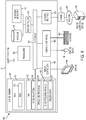
- FIG. 1 shows a PET system 10 featuring CBM acquisition.
- the PET system 10 includes rings of detectors 16, a bed 20, coincidence processors 22, a memory 26, and a central controller 28.
- the central controller 28, memory 26, and/or a display are part of the PET system 10 or are separate (e.g., a computer or workstation). Additional, different, or fewer components may be provided.
- the system is a computer without the detectors 16 and bed 20, instead relying on data acquired by a separate scanner.
- the PET system 10 includes power supplies, communications systems, and user interface systems.
- the bed 20 is a gurney, table, or other support to hold an examination subject such as a patient.
- a robot, gears, cable, track, and/or other device moves the bed 20.
- the movement is along an axial dimension represented by double arrow 24.
- the detectors 16 and/or PET scanner 10 form a bore or hollow cylinder through which the bed 20 moves the patient.
- the distance from the axial axis is the radial distance.
- the angle about the axial axis is the azimuth.
- Other coordinate systems such as a cylindrical or polar coordinate system, may be used.
- the movement is continuous, at least during part of the scanning.
- the bed 20, while supporting the patient, is moved at a same or a varying velocity along the axial dimension 24.
- the head of the patient is scanned with 1.5 mm/s movement of the patient, and the torso is scanned with 1.0 mm/s movement of the patient.
- Other combinations of the same or different rates, with or without a greater number of different velocities, may be used.
- the movement may pass the patient through the bore or merely partly into the bore.
- the movement is with or without acceleration.
- the movement is back and forth, scanning the patient multiple times in a cyclical pattern. A single pass may be used in other embodiments.
- the movement occurs during scanning (e.g., detection or measurement) by the detectors 16.
- the PET detectors 16 are crystals or other photon detectors.
- the detectors 16 are scintillation crystals coupled to avalanche photo diodes.
- scintillation crystals are coupled with photomultiplier tubes.
- the scintillation crystals are bismuth germanium oxide, gadolinium oxyorthosilicate, or lutetium oxyorthosilicate crystals, but other crystals may be used.
- the detectors 16 are arranged individually or in groups. Blocks or groups of detectors 16 are arranged in any pattern around the bore.
- FIG. 2 represents blocks of detectors 16 arranged as separate rings around the bore. The rings are shown spaced apart, but are placed adjacent or abutting each other. Any gap may be provided between blocks within a ring, detectors within a block, and/or between rings. Any number of detectors in a block (e.g., 8 or 16), detector blocks in a ring, and/or rings may be used.
- the separate detectors 16 of each ring have their own singles rate and/or efficiency.
- the rings may extend completely or only partially around the bore.
- the PET system 10 is a nuclear imaging system.
- the detectors 16 detect gamma rays emitted indirectly by a positron-emitting tracer. Pairs of gamma rays generated by a same positron may be detected using the ring of the detectors 16. The pairs of gamma rays travel about 180 degrees apart. If the direction of travel intersects the arrangement of detectors 16 at two locations, a coincident pair may be detected. To distinguish specific pairs, the coincidence of detected gamma rays is determined. The timing of receipt is used to pair the detected gamma rays.
- the patient passes through the rings.
- a given part (e.g., organ) of the patient is within different rings at different times due to the continuous bed motion.
- the line-of-responses for the same part of the patient and corresponding actual three-dimensional location (i.e., point along the line-of-response) is at different locations at different times.
- the detectors 16 continue to detect gamma rays as the bed 20 and patient moves so different lines-of-response may be for the part of the patient at different positions within the bore.
- Each individual detection output from the detectors 16 includes energy, position, and timing information.
- the detectors 16 output energy information and a receiving processor determines the timing and position (e.g., based on port assignment or connections).
- the timing information is used to determine coincidence of detection by different detectors by the coincidence processors 22. Pairs of gamma rays associated with a same positron emission are determined. Based on the detected event, an LOR is determined given the detectors involved in the detection of that event.
- the detected events are passed to the memory 26 and/or the central controller 28.
- the coincidence processor 22 implements the computation of normalization coefficients rather than a separate processor 28.
- the central controller 28 connects with the detectors 16, such as through the coincidence processors 22.
- the central controller 28 is a general processor, digital signal processor, graphics processing unit, application specific integrated circuit, field programmable gate array, digital circuit, analog circuit, combinations thereof, or other now known or later developed device for processing detected line-of-response events, computing normalization coefficients, normalizing, and/or reconstructing.
- the central controller 28 is a single device, a plurality of devices, or a network. For more than one device, parallel or sequential division of processing may be used. Different devices making up the processor 20 may perform different functions, such as one processor for calculating normalization coefficients and another processor for normalizing the line-of-response data.
- the central controller 28 is a control processor or other processor of the PET system 10. In other embodiments, the central controller 28 is part of a separate workstation or computer.
- the central controller 28 operates pursuant to stored instructions to perform various acts described herein, such as determining decay correction efficiency, determining a singles rate for a given time, determining detection time efficiency, calculating the normalization coefficients, normalizing the line-of-response data, and/or reconstruction.
- the central controller 28 is configured by software and/or hardware to perform any or all of the acts of the method summarized in FIG. 3 .
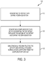
- FIG. 3 is a flowchart 100 illustrating a method for simultaneously monitoring a PET scanner performance during a CBM acquisition, wherein the PET scanner has a patient bed that moves a patient in an axial bed motion through the PET scanner during the CBM acquisition.
- the method comprises (a) generating TOF patient data during the CBM acquisition, while accounting for the axial motion of the patient bed during the CBM acquisition, as a first data set (see Box 110 ); (b) generating a complimentary data set by integrating the TOF patient data over the axial motion of the patient bed during the CBM acquisition (see Box 120 ); and (c) simultaneously reconstructing the activity and crystal efficiency normalization coefficient from the complimentary data set (see Box 130 ).
- the operation and configuration of the central controller 28 is first described in general below.
- One example implementation is described in more detail in the following discussion.
- the central controller 28 is configured to determine normalization coefficients.
- the weighting to account for differences in efficiency for detecting different lines of response relative to the patient is calculated.
- CBM the lines-of-response change axial position over time when considered relative to the patient.
- various detector pairs and other factors contribute to the efficiency of detection. These factors, which may vary over time, are included in the computation of the normalization coefficients.
- the central controller 28 accounts for the decay.
- a decay correction efficiency is determined for an isotope used during the PET scan.
- the isotope's decay characteristic changes over time. This variation in decay is used for the decay correction efficiency.
- the central controller 28 accounts for the velocity variation of the bed and patient. As the velocity of the bed changes, the detection time efficiency changes. The detection time efficiency at different times and corresponding positions of the bed or patient during the PET scan is determined based, in part, on the velocity.
- the central controller 28 may account for other factors as well, such as the time variation of the singles rate and/or normalization of the scanner (e.g., normalization used in S&S or other scanning protocols without the axial bed motion during the scan).
- the central controller 28 applies the normalization coefficients. For each given LOR, the activity is weighted by the normalization coefficient for that LOR.
- the central controller 28 or another processor may reconstruct the object space from the normalized LOR.
- the central controller 28 uses the events (e.g., line-of-response events), empirical information (e.g., global singles rate), and/or known information (e.g., decay correction constant) stored in the memory 26 for processing.
- the data bypasses the memory 26, is temporarily stored in the memory 26, or is loaded from the memory 26.
- the detected events LOR information (e.g., sinograms), time step, singles rate, decay information, scanner normalization information, CBM normalization coefficients, reconstructed image, or other data is stored in the memory 26.
- the data is stored in any format.
- the memory 26 is a buffer, cache, RAM, removable media, hard drive, magnetic, optical, database, or other now known or later developed memory.
- the memory 26 is a single device or group of two or more devices.
- the memory 26 is part of the PET system 10 or a remote workstation or database, such as a PACS memory.
- the memory 26 is additionally or alternatively a non-transitory computer readable storage medium with processing instructions.
- the memory 26 stores data representing instructions executable by the programmed central controller 28 for computing normalization coefficients in continuous bed motion acquisition.
- the instructions for implementing the processes, methods and/or techniques discussed herein are provided on non-transitory computer-readable storage media or memories, such as a cache, buffer, RAM, removable media, hard drive or other computer readable storage media.
- Computer readable storage media include various types of volatile and nonvolatile storage media. The functions, acts or tasks illustrated in the figures or described herein are executed in response to one or more sets of instructions stored in or on computer readable storage media.
- the functions, acts or tasks are independent of the particular type of instructions set, storage media, processor or processing strategy and may be performed by software, hardware, integrated circuits, firmware, micro code and the like, operating alone or in combination.
- processing strategies may include multiprocessing, multitasking, parallel processing and the like.
- the instructions are stored on a removable media device for reading by local or remote systems.
- the instructions are stored in a remote location for transfer through a computer network or over telephone lines.
- the instructions are stored within a given computer, CPU, GPU, or system.
- the PET system 10 may include a display.
- the central controller 28 reconstructs the patient or object being scanned from the normalized line-of-response data.
- the reconstruction is used for three-dimensional rendering, multi-planar reconstruction, or two-dimensional imaging of the function of the object or patient.
- the images are displayed on the display.
- the display is a CRT, LCD, plasma screen, projector, printer, or other output device for showing an image.
- the method for simultaneous scanner performance monitoring during a patient scanning by CBM acquisition involves CBM Data Rebinning.
- CBM Data Rebinning There are two systems of coordinates in CBM acquisition as illustrated in FIGS. 4A and 4B . Only the axial axis of the patient bed is shown. One is laboratory, which is aligned with a scanner. The second is moving, where the object is stationary.
- the CBM scanner data are represented by transaxial radial coordinate ⁇ , azimuthal coordinate ⁇ , and axial plane coordinate z, which includes a polar angle.
- the moving object virtual LORs have the same transaxial coordinates, but are described by different axial coordinate ⁇ Let us denote a function in which we map coordinate ⁇ onto the scanner system coordinate as z ( ⁇ ,t ) .
- This function uses object/bed axial motion knowledge.
- the function aligns laboratory and moving system axial coordinates with the nearest neighbor approximation in order to preserve Poisson statistics during data rebinning.
- the rebinner produces two types of data: one data set for A (activity reconstruction) and a complimentary data set for CE estimations.
- ⁇ is the decay correction constant for a specific isotope
- ⁇ is Kronecker's delta
- d is the dead time correction factor
- t acq CBM acquisition time.
- Dead time correction which accommodates for signal loss when detector processes relatively high count rate, is time dependent due to the variable single rate.
- Equation (2) describes the averaging process of virtual LOR efficiency over scanner LOR efficiencies and is discussed in more detail by the inventor in V.Y. Panin, A.M. Smith, J. Hu, F. Kehren and M.E. Casey, "Continuous bed motion on clinical scanner: Design, Data Correction and Reconstruction", Phys. Med. Bio., vol. 59, pp. 6153-6174, 2014 .
- the CBM normalization array Due to integration over axial movement in (2), the CBM normalization array loses information about the axial CE structure. Therefore, the described data set is used for activity reconstruction, assuming known CEs.
- CE-step modeled true p includes attenuation in the blurring operation. Due to integration over movement in (6), the axial structure of the activity distribution will be lost.
- the total acquisition time can be different between (2) and (6), since modeling in (5) should not include projection outside the axial range of the reconstructed activity field-of-view (FOV). Random means are different between the two data sets as well and are estimated differently from delay events.
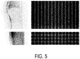
- Simultaneous activity and crystal efficiency normalization component reconstruction can be carried out using the two data sets shown in FIG. 5 .
- the first column represents modeled activity projection.
- the second column represents normalization array, direct planes.
- the first row is the activity reconstruction step (A-step) and the second row is the CE normalization component reconstruction step (CE-step).
- Vertical axis is axial direction. The optimization is performed by iterations; each is divided into the two steps described above.
- the A-step is the activity update with the fixed normalization (efficiencies) array, where CBM TOF data are used.
- the CE-step is the efficiencies updated by the iterative algorithm described in V.Y. Panin, "Monotonic Iterative Algorithms for Crystal Efficiencies Estimation from Normalization Data and Single Rates Estimation from Compressed Random Coincidence Data," 2013 IEEE Nucl. Sci. Symp. and Med. Imag. Conf. (Seoul, Korea), M23-1, 2013 , where the motion blurred activity and scatter distributions will be known from the A-step.
- complimentary TOF or non-TOF data are used and four iterations are performed in the estimation of CE.
- TOF information was eliminated in the computing of A and B, where p j and S j represent summation of p jT and S jT over TOF bin index T . However, TOF information is preserved in the computing of C . If non-TOF data are used in the CE-step, then the computing of C has no summation over the T index.
- Each step uses a simultaneous monotonic update algorithm.
- the two steps together can represent the sequential update method.
- the method can be interpreted as regular activity ML reconstruction with a nested loop of CE normalization component estimation, which uses effectively the same data yet is compressed differently.
- ML-ACE will denote CE normalization component estimations from TOF/non-TOF CE-step data.
- the ML-ACE initial condition was CE initiated by the average block values and uniform activity distribution. Three iterations of the sequential update method were performed. This effectively resulted in three iterations and 21 subsets of OS-EM activity reconstruction and 12 iterations of CE normalization component estimation.
- FIG. 9 illustrates an exemplary computing environment 900 within which includes an embodiments of the central controller 28 of FIG. 1 .
- computing environment 900 can be used to implement the method disclosed herein.
- Computers and computing environments, such as central controller 28 and computing environment 900, are known to those of skill in the art and thus are described briefly here.
- the central controller 28 can include a communication mechanism such as a system bus 921 or other communication mechanism for communicating information within the central controller 28.
- the central controller 28 further includes one or more processors 920 coupled with the system bus 921 for processing the information.
- the processors 920 can include one or more central processing units (CPUs), graphical processing units (GPUs), or any other processor known in the art. More generally, a processor can include a device for executing machine-readable instructions stored on a computer readable medium, for performing tasks and can comprise any one or combination of, hardware and firmware. A processor can also comprise memory storing machine-readable instructions executable for performing tasks. A processor acts upon information by manipulating, analyzing, modifying, converting or transmitting information for use by an executable procedure or an information device, and/or by routing the information to an output device. A processor can use or comprise the capabilities of a computer, controller or microprocessor, for example, and be conditioned using executable instructions to perform special purpose functions not performed by a general purpose computer.
- CPUs central processing units
- GPUs graphical processing units
- a processor can be coupled (electrically and/or as comprising executable components) with any other processor enabling interaction and/or communication there-between.
- a user interface processor or generator can include electronic circuitry or software or a combination of both for generating display images or portions thereof.
- a user interface can comprise one or more display images enabling user interaction with a processor or other device
- the central controller 28 also includes a system memory 930 coupled to the system bus 921 for storing information and instructions to be executed by processors 920.
- the system memory 930 can include computer readable storage media in the form of volatile and/or nonvolatile memory, such as read only memory (ROM) 931 and/or random access memory (RAM) 932.
- the RAM 932 can include other dynamic storage device(s) (e.g., dynamic RAM, static RAM, and synchronous DRAM).
- the ROM 931 can include other static storage device(s) (e.g., programmable ROM, erasable PROM, and electrically erasable PROM).
- system memory 930 can be used for storing temporary variables or other intermediate information during the execution of instructions by the processors 920.
- a basic input/output system 933 (BIOS) containing the basic routines that help to transfer information between elements within central controller 28, such as during start-up, can be stored in the ROM 931.
- RAM 932 can contain data and/or program modules that are immediately accessible to and/or presently being operated on by the processors 920.
- System memory 930 can additionally include, for example, operating system 934, application programs 935, other program modules 936 and program data 937.
- the central controller 28 can also include a disk controller 940 coupled to the system bus 921 to control one or more storage devices for storing information and instructions, such as a magnetic hard disk 941 and a removable media drive 942 (e.g., floppy disk drive, compact disc drive, tape drive, and/or solid state drive).
- Storage devices can be added to the central controller 28 using an appropriate device interface (e.g., a small computer system interface (SCSI), integrated device electronics (IDE), Universal Serial Bus (USB), or FireWire).
- SCSI small computer system interface
- IDE integrated device electronics
- USB Universal Serial Bus
- FireWire FireWire
- the central controller 28 can also include a display controller 965 coupled to the system bus 921 to control a display or monitor 966, such as a liquid crystal display (LCD), for displaying information to a computer user.
- the computer system includes an input interface 960 and one or more input devices, such as a keyboard 962 and a pointing device 961, for interacting with a computer user and providing information to the processors 920.
- the pointing device 961 for example, can be a mouse, a light pen, a trackball, or a joy stick for communicating direction information and command selections to the processors 920 and for controlling cursor movement on the display 966.
- the display 966 can provide a touch screen interface which allows input to supplement or replace the communication of direction information and command selections by the pointing device 961.
- the central controller 28 can perform a portion or all of the processing steps of embodiments in response to the processors 920 executing one or more sequences of one or more instructions contained in a memory, such as the system memory 930.
- a memory such as the system memory 930.
- Such instructions can be read into the system memory 930 from another computer readable medium, such as a magnetic hard disk 941 or a removable media drive 942.
- the magnetic hard disk 941 can contain one or more data stores and data files used by various embodiments. Data store contents and data files can be encrypted to improve security.
- the processors 920 can also be employed in a multiprocessing arrangement to execute the one or more sequences of instructions contained in system memory 930.
- hard-wired circuitry can be used in place of or in combination with software instructions. Thus, embodiments are not limited to any specific combination of hardware circuitry and software.
- Some embodiments include software instructions written in a high level language, such as C, C++, C#, Java, Fortran or Python. Some embodiments are written for a multi-paradigm numerical computing environment, such as Matlab, sold by Mathworks, Inc. of Natick, Massachusetts, or the like.
- the central controller 28 can include at least one computer readable medium or memory for holding instructions and for containing data structures, tables, records, or other data described herein.
- the term "computer readable medium” as used herein refers to any non-transitory machine-readable storage medium that participates in providing instructions to the processors 920 for execution.
- a computer readable medium can take many forms including, but not limited to, non-transitory, non-volatile media and volatile media.
- Nonlimiting examples of non-volatile media include optical disks, solid state drives, magnetic disks, and magneto-optical disks, such as magnetic hard disk 941 or removable media drive 942.
- Nonlimiting examples of volatile media include dynamic memory, such as dynamic random access memory 930.
- the central controller 28 can operate in a networked environment using logical connections to one or more remote computers, such as remote computing device 980.
- Remote computing device 980 can be a personal computer (laptop or desktop), a mobile device, a server, a router, a network PC, a peer device or other common network node, and typically includes many or all of the elements described above relative to central controller 28.
- central controller 28 can include modem 972 for establishing communications over a network 971, such as the Internet. Modem 972 can be connected to system bus 921 via user network interface 970, or via another appropriate mechanism.
- Network 971 can include, but is not limited to, the Internet, an intranet, a local area network (LAN), a wide area network (WAN), a metropolitan area network (MAN), a personal area network (PAN) a direct connection or series of connections, a cellular telephone network, or any other network or medium capable of facilitating communication between central controller 28 and other computers (e.g., remote computing device 980).
- the network 971 can be wired, wireless or a combination thereof. Wired connections can be implemented using Ethernet, Universal Serial Bus (USB), RJ-6, or any other wired connection.
- Wireless connections can be implemented using Wi-Fi, WiMAX, and Bluetooth, infrared, cellular networks, satellite or any other wireless connection methodology. Additionally, several networks can work alone or in communication with each other to facilitate communication in the network 971.
- An activity performed automatically is performed in response to one or more executable instructions or device operation without user direct initiation of the activity.
- the methods and system described herein can be at least partially embodied in the form of computer-implemented processes and apparatus for practicing those processes.
- the disclosed methods can also be at least partially embodied in the form of tangible, non-transitory machine readable storage media encoded with computer program code.
- the media can include, for example, RAMs, ROMs, CD-ROMs, DVD-ROMs, BD-ROMs, hard disk drives, flash memories, or any other non-transitory machine-readable storage medium, wherein, when the computer program code is loaded into and executed by a computer, the computer becomes an apparatus for practicing the method.
- the methods can also be at least partially embodied in the form of a computer into which computer program code is loaded and/or executed, such that, the computer becomes a special purpose computer for practicing the methods.
- the computer program code segments configure the processor to create specific logic circuits.
- the methods can alternatively be at least partially embodied in a digital signal processor formed of application specific integrated circuits for performing the methods.
- a non-transitory, machine readable storage medium encoded with computer program software such that when a processor executes the computer program software, the processor performs a method for simultaneously monitoring a positron emission tomography (PET) scanner performance during a continuous-bed-motion (CBM) acquisition is disclosed, wherein the PET scanner has a patient bed that moves a patient in an axial motion through the PET scanner during the CBM acquisition, the method comprising:
- the method of the present disclosure was verified on Siemens mCT Flow patient data acquired with 0.8 mm/sec bed speed in list mode. During histogramming of the list mode file, a fraction of counts acquired on LORs that originated in the four blocks was withdrawn. This artificially created hot spots in the affected block's CE map. The central crystals maintained original efficiency, while the rest of the crystals lost 50% of their original efficiency. This data set will be denoted as the one with defects present. A defect-absent (all counts used) data set was produced as well.
- the gold standard CE normalization component estimation was extracted from the daily QC normalization file. Note that the coordinate ascent algorithm is used in Siemens daily QC software for CE normalization component estimations, making direct comparison with ML-ACE results difficult.
- the 233 planes of image data which corresponds to an axial extend of three mCT S&S acquisitions, was reconstructed. Scatter was estimated using the gold standard CE normalization component estimation and was fixed in investigation. Attenuation was produced in a regular way based on the CT scan. Dead time and decay corrections were ignored in normalization array computations.
- A-step CBM random data were used as-is, while CE-step random data underwent a random smoothing procedure with 50 iterations of monotonic algorithm.
- CBM data were reconstructed all at once, resulting in production of a single image.
- a data chunking scheme was not used, contrary to clinical environment reconstruction.
- the image was rescaled according to the total activity of the gold standard image, which was 3 iterations of OSEM reconstruction using daily QC CE normalization. While activity and CE each can be rescaled consistently so that modeled projections will maintain their original scales, this did not hold true for the scatter component. Scatter was constant during the investigations and CE scaling affected its scale
- CE In the CE-step, all available data were used. Outside of the true events support, CE are modeled through scatter components. True events modeled projections were zeroed outside the patient boundary (image support is derived from the CT-based attenuation map) before implementing the blurring operator (5).
- the blurring operator (5) is a simple summation over modeled projection planes.
- the activity reconstructions were 400 x 400 x 233 (image volume in 400 voxel in xy direction and y direction and 233 voxel in axial, z, direction), 2 x 2 x 2 mm (each voxel size, apparently cubic one).
- the four ring mCT scanner consists of 48 transaxial blocks (horizontal direction in the following figures) and 4 axial blocks (vertical). Each of the 48 blocks contains 13 x 13 crystals (4 x 4 x 2 mm each). Therefore, the CE array consists of 624 x 52 detectors.
- a CE contrast-noise trade-off curve was built. Recovery of hot spots was computed as the ratio of the central crystals in an affected block to the central crystals of a neighboring block. Recovery was averaged over all four affected blocks. In order to understand the noise property, we computed the standard deviation of each crystal efficiency in one block (total 13 x 13 crystals) over all 48 transaxial blocks, normalized by the average block efficiency value. Noise was computed as the average standard deviation over all 13 x 13 crystals. Forty blocks (10 x 4) were used in the noise assessment. Recovery of hot spots versus noise in the crystal efficiencies estimation was considered as a function of the iteration number to understand the algorithm convergence property.
- FIGS. 6A-6C show patient activity reconstructions created by the OSEM reconstruction algorithm using daily QC CE, and by ML-ACE from defect-absent data.
- FIG. 6A shows patient activity by regular OSEM reconstruction with gold standard.
- FIG. 6B shows patient activity by ML-ACE reconstruction.
- FIG. 6C shows the relative difference between the patient activities shown in FIG. 6A and FIG. 6B . Visually these images were practically of identical quality. Nevertheless, the relative difference image, FIG. 6C , reveals that there was a difference in cold spots, such as the outside of the patient support. In regular uptake regions the difference was relatively small, around 5-7%.
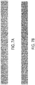
- FIGS. 7A-7C The corresponding ML-ACE crystal efficiencies estimations are presented in FIGS. 7A-7C along with the gold standard, daily QC CE.
- FIG. 7A shows the gold standard crystal efficiencies from morning scan.
- FIG. 7B shows CE of ML-ACE reconstruction.
- FIG. 7C shows CE normalized transaxial profile, averaged over axial dimension.
- the black curve in the graph in FIG. 7C represents gold standard QC CE, and the gray curve represents ML-ACE CE.
- the noise level appears to be less compared to that of the gold standard estimation due to a difference in CE estimation algorithms. Both efficiency distributions displayed a similar uncommon block pattern of certain crystals.
- Overall the CE estimation uniformity was satisfactory, according to FIG. 7C . We observed that random smoothing and zeroing of residual reconstruction activity outside of patient boundaries was essential in assuring overall CE estimation uniformity.
- FIGS. 8A-8E represent patient activity and CE estimation reconstructions from defect-induced (i.e. defect-present) data.
- FIG. 8A shows ML-ACE reconstructed CE.
- FIG. 8B shows patient transaxial slices used in generating the FGS. 8C and 8D.
- FIG. 8C shows an image of relative difference between OSEM reconstruction using daily QC normalization from defect-free and defect-induced data.
- FIG. 8D shows an image of relative difference between ML-ACE reconstruction from defect-free and defect-induced data.
- the influence of normalization mismatch was relatively mild. This supports the currently well-known fact that TOF reconstruction significantly reduces correction factor mismatch related artifacts.
- FIG. 8E shows CE hot spot recovery versus noise.
- the black curve represents non-TOF nested loop ML-ACE reconstruction
- the red curve represents TOF nested loop ML-ACE reconstruction.
- FIG. 8E demonstrates that there was a benefit, through relatively small, in the TOF (rather than smaller size data in non-TOF) CE nested loop of ML-ACE.
- FIG. 8E demonstrates that there was relatively small benefit in the TOF nested loop of ML-ACE. Therefore, production of non-TOF data for the CE step seems to be a more attractive option from a practical point of view.
- the proposed CE estimation scheme is applicable for the daily QC procedure (known activity object) as well.
- object position especially in the axial direction, will need to be determined from the A-step.
- the axially short object can be used in CBM acquisition coverage of the whole FOV. This phantom will be easier to manufacture and handle during the daily routine.
- CBM patient self-normalization and QC are feasible with the help of additional data rebinning.
- Patient data from a Siemens mCT scanner were used to validate the proposed scheme.
- Initial investigations showed the proposed method can produce crystal efficiencies maps comparable to those of the daily phantom scans and therefore is suitable for a patient based QC procedure.
Landscapes
- Health & Medical Sciences (AREA)
- Life Sciences & Earth Sciences (AREA)
- Engineering & Computer Science (AREA)
- Physics & Mathematics (AREA)
- Medical Informatics (AREA)
- High Energy & Nuclear Physics (AREA)
- Molecular Biology (AREA)
- General Physics & Mathematics (AREA)
- Radiology & Medical Imaging (AREA)
- General Health & Medical Sciences (AREA)
- Nuclear Medicine, Radiotherapy & Molecular Imaging (AREA)
- Spectroscopy & Molecular Physics (AREA)
- Biophysics (AREA)
- Public Health (AREA)
- Biomedical Technology (AREA)
- Heart & Thoracic Surgery (AREA)
- Surgery (AREA)
- Animal Behavior & Ethology (AREA)
- Optics & Photonics (AREA)
- Veterinary Medicine (AREA)
- Pathology (AREA)
- Quality & Reliability (AREA)
- Computer Vision & Pattern Recognition (AREA)
- Theoretical Computer Science (AREA)
- Chemical & Material Sciences (AREA)
- Crystallography & Structural Chemistry (AREA)
- Nuclear Medicine (AREA)
Applications Claiming Priority (1)
| Application Number | Priority Date | Filing Date | Title |
|---|---|---|---|
| US15/586,485 US10482596B2 (en) | 2017-05-04 | 2017-05-04 | Normalization crystal efficiencies estimation for continuous motion bed acquisition |
Publications (3)
| Publication Number | Publication Date |
|---|---|
| EP3399346A1 true EP3399346A1 (de) | 2018-11-07 |
| EP3399346C0 EP3399346C0 (de) | 2023-10-25 |
| EP3399346B1 EP3399346B1 (de) | 2023-10-25 |
Family
ID=62104188
Family Applications (1)
| Application Number | Title | Priority Date | Filing Date |
|---|---|---|---|
| EP18170350.5A Active EP3399346B1 (de) | 2017-05-04 | 2018-05-02 | Normierungskristalleffizienzschätzung für die kontinuierliche bewegungsbetterfassung |
Country Status (3)
| Country | Link |
|---|---|
| US (1) | US10482596B2 (de) |
| EP (1) | EP3399346B1 (de) |
| CA (1) | CA3003664C (de) |
Cited By (1)
| Publication number | Priority date | Publication date | Assignee | Title |
|---|---|---|---|---|
| US20220309718A1 (en) * | 2019-10-09 | 2022-09-29 | Siemens Medical Solutions Usa, Inc. | Continuous bed motion acquisition with axially short phantom for pet imaging system setup and quality control |
Families Citing this family (5)
| Publication number | Priority date | Publication date | Assignee | Title |
|---|---|---|---|---|
| CN109938765B (zh) * | 2019-03-15 | 2023-01-17 | 上海联影医疗科技股份有限公司 | Pet床码识别方法、系统、可读存储介质和设备 |
| CN110301927B (zh) * | 2019-07-04 | 2023-05-30 | 沈阳智核医疗科技有限公司 | 确定晶体固有效率的方法、装置、存储介质及医疗设备 |
| CN112205996B (zh) * | 2020-11-01 | 2023-05-26 | 南昌华亮光电有限责任公司 | 基于光子随机偏移量的图像加密系统与方法 |
| CN117202852A (zh) * | 2021-06-08 | 2023-12-08 | 中加健康工程研究院(合肥)有限公司 | 探测pet设备的晶体效率的方法、装置、系统、介质及程序 |
| EP4242696A1 (de) | 2022-03-10 | 2023-09-13 | Positrigo AG | Verfahren zur bestimmung der relativen effizienz von detektorelementen in einer pet-abtastvorrichtung |
Citations (4)
| Publication number | Priority date | Publication date | Assignee | Title |
|---|---|---|---|---|
| US20140200848A1 (en) * | 2013-01-11 | 2014-07-17 | Siemens Medical Solutions Usa, Inc. | Normalization Coefficients in PET Continuous Bed Motion Acquisition |
| US20150199302A1 (en) * | 2012-10-26 | 2015-07-16 | The Regents Of The University Of California | Image-based point-spread-function modelling in time-of-flight positron-emission-tomography iterative list-mode reconstruction |
| US20150297168A1 (en) | 2014-04-18 | 2015-10-22 | Siemens Medical Solutions Usa, Inc. | Patient Based Detector Crystal Quality Control for Time of Flight Acquisition |
| US20170091963A1 (en) * | 2015-09-28 | 2017-03-30 | Siemens Medical Solutions Usa, Inc. | Motion correction in a projection domain in time of flight positron emission tomography |
Family Cites Families (1)
| Publication number | Priority date | Publication date | Assignee | Title |
|---|---|---|---|---|
| US9044153B2 (en) | 2013-01-09 | 2015-06-02 | Siemens Medical Solutions Usa, Inc. | Random sinogram variance reduction in continuous bed motion acquisition |
-
2017
- 2017-05-04 US US15/586,485 patent/US10482596B2/en active Active
-
2018
- 2018-05-02 EP EP18170350.5A patent/EP3399346B1/de active Active
- 2018-05-02 CA CA3003664A patent/CA3003664C/en active Active
Patent Citations (4)
| Publication number | Priority date | Publication date | Assignee | Title |
|---|---|---|---|---|
| US20150199302A1 (en) * | 2012-10-26 | 2015-07-16 | The Regents Of The University Of California | Image-based point-spread-function modelling in time-of-flight positron-emission-tomography iterative list-mode reconstruction |
| US20140200848A1 (en) * | 2013-01-11 | 2014-07-17 | Siemens Medical Solutions Usa, Inc. | Normalization Coefficients in PET Continuous Bed Motion Acquisition |
| US20150297168A1 (en) | 2014-04-18 | 2015-10-22 | Siemens Medical Solutions Usa, Inc. | Patient Based Detector Crystal Quality Control for Time of Flight Acquisition |
| US20170091963A1 (en) * | 2015-09-28 | 2017-03-30 | Siemens Medical Solutions Usa, Inc. | Motion correction in a projection domain in time of flight positron emission tomography |
Non-Patent Citations (4)
| Title |
|---|
| M. DEFRISE ET AL.: "A Normalization Technique for 3D PET Data", PHYS. MED. BIOL., vol. 36, 1991, pages 939 - 952, XP002246408, DOI: doi:10.1088/0031-9155/36/7/003 |
| V.Y. PANIN: "Monotonic Iterative Algorithms for Crystal Efficiencies Estimation from Normalization Data and Single Rates Estimation from Compressed Random Coincidence Data", IEEE NUCL. SCI. SYMP. AND MED. IMAG. CONF., 2013 |
| V.Y. PANIN; A.M. SMITH; J. HU; F. KEHREN; M.E. CASEY: "Continuous bed motion on clinical scanner: Design, Data Correction and Reconstruction", PHYS. MED. BIO., vol. 59, 2014, pages 6153 - 6174, XP020270497, DOI: doi:10.1088/0031-9155/59/20/6153 |
| VY PANIN ET AL: "Continuous bed motion on clinical scanner: design, data correction, and reconstruction", PHYSICS IN MEDICINE AND BIOLOGY, INSTITUTE OF PHYSICS PUBLISHING, BRISTOL GB, vol. 59, no. 20, 25 September 2014 (2014-09-25), pages 6153 - 6174, XP020270497, ISSN: 0031-9155, [retrieved on 20140925], DOI: 10.1088/0031-9155/59/20/6153 * |
Cited By (3)
| Publication number | Priority date | Publication date | Assignee | Title |
|---|---|---|---|---|
| US20220309718A1 (en) * | 2019-10-09 | 2022-09-29 | Siemens Medical Solutions Usa, Inc. | Continuous bed motion acquisition with axially short phantom for pet imaging system setup and quality control |
| US11961164B2 (en) * | 2019-10-09 | 2024-04-16 | Siemens Medical Solutions Usa, Inc. | Continuous bed motion acquisition with axially short phantom for PET imaging system setup and quality control |
| US12141898B2 (en) | 2019-10-09 | 2024-11-12 | Siemens Medical Solutions Usa, Inc. | Continuous bed motion acquisition with axially short phantom for PET imaging system setup and quality control |
Also Published As
| Publication number | Publication date |
|---|---|
| EP3399346C0 (de) | 2023-10-25 |
| CA3003664A1 (en) | 2018-11-04 |
| CA3003664C (en) | 2020-08-18 |
| US20180322626A1 (en) | 2018-11-08 |
| EP3399346B1 (de) | 2023-10-25 |
| US10482596B2 (en) | 2019-11-19 |
Similar Documents
| Publication | Publication Date | Title |
|---|---|---|
| EP3399346B1 (de) | Normierungskristalleffizienzschätzung für die kontinuierliche bewegungsbetterfassung | |
| Ollinger | Model-based scatter correction for fully 3D PET | |
| US12141898B2 (en) | Continuous bed motion acquisition with axially short phantom for PET imaging system setup and quality control | |
| Tong et al. | Image reconstruction for PET/CT scanners: past achievements and future challenges | |
| EP3494547B1 (de) | Time-of-flight (tof)-pet-bildrekonstruktion mit lokal modifizierten tof-kernen | |
| EP2852931B1 (de) | Schnelle streuungsmessung in einer pet-rekonstruktion | |
| US9747701B2 (en) | Systems and methods for emission tomography quantitation | |
| US9645261B2 (en) | Normalization coefficients in PET continuous bed motion acquisition | |
| US7777189B2 (en) | Dirty isotope PET reconstruction | |
| EP2984631B1 (de) | Verfahren zur modellierung und erfassung von kaskaden-gammas in bildern | |
| US7928727B2 (en) | Adapting acquisition time in nuclear imaging | |
| US10126439B2 (en) | Reconstruction with multiple photopeaks in quantitative single photon emission computed tomography | |
| Hamill et al. | Energy‐based scatter estimation in clinical PET | |
| US9916670B1 (en) | Fast, efficient, and list-mode compatible tomographic image reconstruction using a novel quadratic surrogate | |
| US12475613B2 (en) | Scatter estimation for PET from image-based convolutional neural network | |
| US10354417B2 (en) | Medical image processing apparatus and medical image diagnosis apparatus and medical image processing method | |
| US12488446B2 (en) | Apparatus and methods for unsupervised image denoising using double over-parameterization | |
| Panin | Simultaneous activity and crystal efficiencies reconstruction for continuous motion bed acquisition | |
| Shopa | High-quality iterative TOF MLEM reconstruction for short scans in total-body J-PET | |
| Yuan et al. | GPU‐based list‐mode TOF PET image reconstruction with complete correction techniques | |
| Gillen et al. | Towards Accurate Partial Volume Correction–Perturbation for SPECT Resolution Estimation | |
| Schoenahl | Performance characterization and development of quantitative procedures for PET-CT scanners. | |
| Ralli | 4D reconstruction of oncological dynamic PET data | |
| Valiollahzadeh | Compressive sensing in positron emission tomography (PET) imaging | |
| Fuin | Estimation of the Image Quality in Emission Tomography: Application to Optimization of SPECT System Design |
Legal Events
| Date | Code | Title | Description |
|---|---|---|---|
| PUAI | Public reference made under article 153(3) epc to a published international application that has entered the european phase |
Free format text: ORIGINAL CODE: 0009012 |
|
| STAA | Information on the status of an ep patent application or granted ep patent |
Free format text: STATUS: REQUEST FOR EXAMINATION WAS MADE |
|
| 17P | Request for examination filed |
Effective date: 20180502 |
|
| AK | Designated contracting states |
Kind code of ref document: A1 Designated state(s): AL AT BE BG CH CY CZ DE DK EE ES FI FR GB GR HR HU IE IS IT LI LT LU LV MC MK MT NL NO PL PT RO RS SE SI SK SM TR |
|
| AX | Request for extension of the european patent |
Extension state: BA ME |
|
| RBV | Designated contracting states (corrected) |
Designated state(s): AL AT BE BG CH CY CZ DE DK EE ES FI FR GB GR HR HU IE IS IT LI LT LU LV MC MK MT NL NO PL PT RO RS SE SI SK SM TR |
|
| STAA | Information on the status of an ep patent application or granted ep patent |
Free format text: STATUS: EXAMINATION IS IN PROGRESS |
|
| 17Q | First examination report despatched |
Effective date: 20210407 |
|
| GRAP | Despatch of communication of intention to grant a patent |
Free format text: ORIGINAL CODE: EPIDOSNIGR1 |
|
| STAA | Information on the status of an ep patent application or granted ep patent |
Free format text: STATUS: GRANT OF PATENT IS INTENDED |
|
| INTG | Intention to grant announced |
Effective date: 20230818 |
|
| GRAS | Grant fee paid |
Free format text: ORIGINAL CODE: EPIDOSNIGR3 |
|
| GRAA | (expected) grant |
Free format text: ORIGINAL CODE: 0009210 |
|
| STAA | Information on the status of an ep patent application or granted ep patent |
Free format text: STATUS: THE PATENT HAS BEEN GRANTED |
|
| AK | Designated contracting states |
Kind code of ref document: B1 Designated state(s): AL AT BE BG CH CY CZ DE DK EE ES FI FR GB GR HR HU IE IS IT LI LT LU LV MC MK MT NL NO PL PT RO RS SE SI SK SM TR |
|
| REG | Reference to a national code |
Ref country code: GB Ref legal event code: FG4D |
|
| REG | Reference to a national code |
Ref country code: CH Ref legal event code: EP |
|
| REG | Reference to a national code |
Ref country code: DE Ref legal event code: R096 Ref document number: 602018059830 Country of ref document: DE |
|
| REG | Reference to a national code |
Ref country code: IE Ref legal event code: FG4D |
|
| U01 | Request for unitary effect filed |
Effective date: 20231122 |
|
| U07 | Unitary effect registered |
Designated state(s): AT BE BG DE DK EE FI FR IT LT LU LV MT NL PT SE SI Effective date: 20231128 |
|
| PG25 | Lapsed in a contracting state [announced via postgrant information from national office to epo] |
Ref country code: GR Free format text: LAPSE BECAUSE OF FAILURE TO SUBMIT A TRANSLATION OF THE DESCRIPTION OR TO PAY THE FEE WITHIN THE PRESCRIBED TIME-LIMIT Effective date: 20240126 |
|
| PG25 | Lapsed in a contracting state [announced via postgrant information from national office to epo] |
Ref country code: IS Free format text: LAPSE BECAUSE OF FAILURE TO SUBMIT A TRANSLATION OF THE DESCRIPTION OR TO PAY THE FEE WITHIN THE PRESCRIBED TIME-LIMIT Effective date: 20240225 |
|
| PG25 | Lapsed in a contracting state [announced via postgrant information from national office to epo] |
Ref country code: ES Free format text: LAPSE BECAUSE OF FAILURE TO SUBMIT A TRANSLATION OF THE DESCRIPTION OR TO PAY THE FEE WITHIN THE PRESCRIBED TIME-LIMIT Effective date: 20231025 |
|
| PG25 | Lapsed in a contracting state [announced via postgrant information from national office to epo] |
Ref country code: IS Free format text: LAPSE BECAUSE OF FAILURE TO SUBMIT A TRANSLATION OF THE DESCRIPTION OR TO PAY THE FEE WITHIN THE PRESCRIBED TIME-LIMIT Effective date: 20240225 Ref country code: GR Free format text: LAPSE BECAUSE OF FAILURE TO SUBMIT A TRANSLATION OF THE DESCRIPTION OR TO PAY THE FEE WITHIN THE PRESCRIBED TIME-LIMIT Effective date: 20240126 Ref country code: ES Free format text: LAPSE BECAUSE OF FAILURE TO SUBMIT A TRANSLATION OF THE DESCRIPTION OR TO PAY THE FEE WITHIN THE PRESCRIBED TIME-LIMIT Effective date: 20231025 |
|
| PG25 | Lapsed in a contracting state [announced via postgrant information from national office to epo] |
Ref country code: RS Free format text: LAPSE BECAUSE OF FAILURE TO SUBMIT A TRANSLATION OF THE DESCRIPTION OR TO PAY THE FEE WITHIN THE PRESCRIBED TIME-LIMIT Effective date: 20231025 Ref country code: PL Free format text: LAPSE BECAUSE OF FAILURE TO SUBMIT A TRANSLATION OF THE DESCRIPTION OR TO PAY THE FEE WITHIN THE PRESCRIBED TIME-LIMIT Effective date: 20231025 Ref country code: NO Free format text: LAPSE BECAUSE OF FAILURE TO SUBMIT A TRANSLATION OF THE DESCRIPTION OR TO PAY THE FEE WITHIN THE PRESCRIBED TIME-LIMIT Effective date: 20240125 Ref country code: HR Free format text: LAPSE BECAUSE OF FAILURE TO SUBMIT A TRANSLATION OF THE DESCRIPTION OR TO PAY THE FEE WITHIN THE PRESCRIBED TIME-LIMIT Effective date: 20231025 |
|
| U20 | Renewal fee for the european patent with unitary effect paid |
Year of fee payment: 7 Effective date: 20240517 |
|
| PG25 | Lapsed in a contracting state [announced via postgrant information from national office to epo] |
Ref country code: CZ Free format text: LAPSE BECAUSE OF FAILURE TO SUBMIT A TRANSLATION OF THE DESCRIPTION OR TO PAY THE FEE WITHIN THE PRESCRIBED TIME-LIMIT Effective date: 20231025 |
|
| REG | Reference to a national code |
Ref country code: DE Ref legal event code: R097 Ref document number: 602018059830 Country of ref document: DE |
|
| PG25 | Lapsed in a contracting state [announced via postgrant information from national office to epo] |
Ref country code: SK Free format text: LAPSE BECAUSE OF FAILURE TO SUBMIT A TRANSLATION OF THE DESCRIPTION OR TO PAY THE FEE WITHIN THE PRESCRIBED TIME-LIMIT Effective date: 20231025 |
|
| PG25 | Lapsed in a contracting state [announced via postgrant information from national office to epo] |
Ref country code: SM Free format text: LAPSE BECAUSE OF FAILURE TO SUBMIT A TRANSLATION OF THE DESCRIPTION OR TO PAY THE FEE WITHIN THE PRESCRIBED TIME-LIMIT Effective date: 20231025 Ref country code: SK Free format text: LAPSE BECAUSE OF FAILURE TO SUBMIT A TRANSLATION OF THE DESCRIPTION OR TO PAY THE FEE WITHIN THE PRESCRIBED TIME-LIMIT Effective date: 20231025 Ref country code: RO Free format text: LAPSE BECAUSE OF FAILURE TO SUBMIT A TRANSLATION OF THE DESCRIPTION OR TO PAY THE FEE WITHIN THE PRESCRIBED TIME-LIMIT Effective date: 20231025 Ref country code: CZ Free format text: LAPSE BECAUSE OF FAILURE TO SUBMIT A TRANSLATION OF THE DESCRIPTION OR TO PAY THE FEE WITHIN THE PRESCRIBED TIME-LIMIT Effective date: 20231025 |
|
| PLBE | No opposition filed within time limit |
Free format text: ORIGINAL CODE: 0009261 |
|
| STAA | Information on the status of an ep patent application or granted ep patent |
Free format text: STATUS: NO OPPOSITION FILED WITHIN TIME LIMIT |
|
| 26N | No opposition filed |
Effective date: 20240726 |
|
| REG | Reference to a national code |
Ref country code: CH Ref legal event code: PL |
|
| PG25 | Lapsed in a contracting state [announced via postgrant information from national office to epo] |
Ref country code: MC Free format text: LAPSE BECAUSE OF FAILURE TO SUBMIT A TRANSLATION OF THE DESCRIPTION OR TO PAY THE FEE WITHIN THE PRESCRIBED TIME-LIMIT Effective date: 20231025 |
|
| PG25 | Lapsed in a contracting state [announced via postgrant information from national office to epo] |
Ref country code: MC Free format text: LAPSE BECAUSE OF FAILURE TO SUBMIT A TRANSLATION OF THE DESCRIPTION OR TO PAY THE FEE WITHIN THE PRESCRIBED TIME-LIMIT Effective date: 20231025 Ref country code: CH Free format text: LAPSE BECAUSE OF NON-PAYMENT OF DUE FEES Effective date: 20240531 |
|
| PG25 | Lapsed in a contracting state [announced via postgrant information from national office to epo] |
Ref country code: IE Free format text: LAPSE BECAUSE OF NON-PAYMENT OF DUE FEES Effective date: 20240502 |
|
| U20 | Renewal fee for the european patent with unitary effect paid |
Year of fee payment: 8 Effective date: 20250520 |
|
| PGFP | Annual fee paid to national office [announced via postgrant information from national office to epo] |
Ref country code: GB Payment date: 20250610 Year of fee payment: 8 |
|
| PG25 | Lapsed in a contracting state [announced via postgrant information from national office to epo] |
Ref country code: CY Free format text: LAPSE BECAUSE OF FAILURE TO SUBMIT A TRANSLATION OF THE DESCRIPTION OR TO PAY THE FEE WITHIN THE PRESCRIBED TIME-LIMIT; INVALID AB INITIO Effective date: 20180502 |
|
| PG25 | Lapsed in a contracting state [announced via postgrant information from national office to epo] |
Ref country code: HU Free format text: LAPSE BECAUSE OF FAILURE TO SUBMIT A TRANSLATION OF THE DESCRIPTION OR TO PAY THE FEE WITHIN THE PRESCRIBED TIME-LIMIT; INVALID AB INITIO Effective date: 20180502 |