EP3399303A1 - Handheld backscatter imager and imaging method thereof - Google Patents
Handheld backscatter imager and imaging method thereof Download PDFInfo
- Publication number
- EP3399303A1 EP3399303A1 EP16880624.8A EP16880624A EP3399303A1 EP 3399303 A1 EP3399303 A1 EP 3399303A1 EP 16880624 A EP16880624 A EP 16880624A EP 3399303 A1 EP3399303 A1 EP 3399303A1
- Authority
- EP
- European Patent Office
- Prior art keywords
- ray
- passing region
- modulator
- ray passing
- pixel points
- Prior art date
- Legal status (The legal status is an assumption and is not a legal conclusion. Google has not performed a legal analysis and makes no representation as to the accuracy of the status listed.)
- Granted
Links
Images


Classifications
-
- G—PHYSICS
- G01—MEASURING; TESTING
- G01N—INVESTIGATING OR ANALYSING MATERIALS BY DETERMINING THEIR CHEMICAL OR PHYSICAL PROPERTIES
- G01N23/00—Investigating or analysing materials by the use of wave or particle radiation, e.g. X-rays or neutrons, not covered by groups G01N3/00 – G01N17/00, G01N21/00 or G01N22/00
- G01N23/20—Investigating or analysing materials by the use of wave or particle radiation, e.g. X-rays or neutrons, not covered by groups G01N3/00 – G01N17/00, G01N21/00 or G01N22/00 by using diffraction of the radiation by the materials, e.g. for investigating crystal structure; by using scattering of the radiation by the materials, e.g. for investigating non-crystalline materials; by using reflection of the radiation by the materials
- G01N23/203—Measuring back scattering
-
- G—PHYSICS
- G01—MEASURING; TESTING
- G01T—MEASUREMENT OF NUCLEAR OR X-RADIATION
- G01T7/00—Details of radiation-measuring instruments
-
- G—PHYSICS
- G01—MEASURING; TESTING
- G01V—GEOPHYSICS; GRAVITATIONAL MEASUREMENTS; DETECTING MASSES OR OBJECTS; TAGS
- G01V5/00—Prospecting or detecting by the use of ionising radiation, e.g. of natural or induced radioactivity
- G01V5/20—Detecting prohibited goods, e.g. weapons, explosives, hazardous substances, contraband or smuggled objects
- G01V5/22—Active interrogation, i.e. by irradiating objects or goods using external radiation sources, e.g. using gamma rays or cosmic rays
- G01V5/222—Active interrogation, i.e. by irradiating objects or goods using external radiation sources, e.g. using gamma rays or cosmic rays measuring scattered radiation
-
- G—PHYSICS
- G01—MEASURING; TESTING
- G01N—INVESTIGATING OR ANALYSING MATERIALS BY DETERMINING THEIR CHEMICAL OR PHYSICAL PROPERTIES
- G01N2223/00—Investigating materials by wave or particle radiation
- G01N2223/30—Accessories, mechanical or electrical features
- G01N2223/301—Accessories, mechanical or electrical features portable apparatus
-
- G—PHYSICS
- G01—MEASURING; TESTING
- G01N—INVESTIGATING OR ANALYSING MATERIALS BY DETERMINING THEIR CHEMICAL OR PHYSICAL PROPERTIES
- G01N2223/00—Investigating materials by wave or particle radiation
- G01N2223/30—Accessories, mechanical or electrical features
- G01N2223/33—Accessories, mechanical or electrical features scanning, i.e. relative motion for measurement of successive object-parts
- G01N2223/3301—Accessories, mechanical or electrical features scanning, i.e. relative motion for measurement of successive object-parts beam is modified for scan, e.g. moving collimator
-
- G—PHYSICS
- G01—MEASURING; TESTING
- G01N—INVESTIGATING OR ANALYSING MATERIALS BY DETERMINING THEIR CHEMICAL OR PHYSICAL PROPERTIES
- G01N2223/00—Investigating materials by wave or particle radiation
- G01N2223/30—Accessories, mechanical or electrical features
- G01N2223/33—Accessories, mechanical or electrical features scanning, i.e. relative motion for measurement of successive object-parts
- G01N2223/3302—Accessories, mechanical or electrical features scanning, i.e. relative motion for measurement of successive object-parts object and detector fixed
Definitions
- the present disclosure relates to the field of X-ray imaging application, and particularly, to a handheld backscatter imager for inspection of an object and an imaging method of the handheld backscatter imager, here, the object may be luggage, vehicles, walls of buildings, and various objects that need to be identified in aspect of safety of internal structures thereof and goods therein.
- the most commonly used scanning method is a flying-spot scanning, that is: after being collimated and modulated, rays become pencil ray beams (flying-spots), and the latter fast scan an object to be inspected point by point in a first dimensional direction; a plane of the pencil ray beams, together with detector, translates relative to the object to be inspected in a second dimensional direction; a motion speed in the second dimensional direction is greatly lower than a motion speed in the first dimensional direction, and the second dimensional direction is substantially perpendicular to the first dimensional direction; at the same time, a detector receives rays that are scattered back by the object, as a signal of a scanning point at that time, and in the data processing, a two dimensional backscatter image that reflects information of the object can be obtained by point correspondence of the scanning position and the signal point.
- the flying-spot scanning belongs to a point scanning (that scans one point at one time), which is lowest in efficiency and in scanning speed, and takes the longest time, compared to a line scanning (that scans one line at one time) and a surface scanning (that scans one surface at one time).
- the characteristics of the back scattering cause low dosage of the rays, great fluctuation in signals received by the detector, which will result in great noise and poor quality of a final image.
- a usual method is to increase parameters in voltage and current of the X-ray machine or to reduce the scanning speed that was not really fast (that is, to further prolong the scanning time).
- the X-ray machine has very small power due to its limited space and weight, which means that a voltage and a current of the X-ray machine are set to have smaller parameter values.
- the image quality and the scanning time are in a dilemma. If image quality is to be assured, a very low scanning speed will certainly test the operator in stability and durability of the low speed motions, which seriously affects the operation experience; and if scanning time is to be assured, a low image quality will affect accuracy of the determination of the image by the operator.
- the handheld backscatter imager cannot require an operator to operate it in a long scanning time, so a low image quality is the result in most cases.
- At least one object of the present disclosure is to provide a handheld backscatter imager and an imaging method of the handheld backscatter imager, which solve a contradiction between the image quality and the scanning time by a special "flying-line" scanning mode.
- a handheld backscatter imager comprising:
- the controller is further configured to: calculate, based on a successive differential algorithm, a difference value between a currently acquired scattering signal and a formerly acquired scattering signal; calculate, based on currently acquired angular information, spatially angular information of emission of a current X-ray beam; determine a position of the pixel point, corresponding to the current X-ray beam, in the imaging image, and a corresponding compensation value according to the spatially angular information; and determine, based on the difference value and the corresponding compensation value, a pixel point value at the position of the pixel point corresponding to the current X-ray beam, so as to obtain a final scanning image.
- the controller is further configured to control rotation of the modulator.
- the modulator assumes a circular ring shape having a central axis of the X-ray source as its axis, and the at least one X-ray passing region is formed in a ring surface of the circular ring shape.
- the at least one collimator corresponds to the at least one X-ray passing region
- the collimator assumes a sector shape and is provided between the corresponding X-ray passing region of the modulator and the X-ray source, and the corresponding X-ray passing region is designed to be perpendicular to a sector-shaped surface of the collimator.
- the at least one X-ray passing region is designed to have a long and narrow slot configuration.
- the at least one X-ray passing region is designed to have a configuration of a long and narrow column of apertures, formed by a series of apertures connected to one another.
- the at least one X-ray passing region is designed to have a configuration of a long and narrow slot with a smaller diameter end.
- the at least one X-ray passing region is designed to have a configuration of a long and narrow column of apertures, formed by a series of apertures connected to one another and including a smaller-diameter aperture.
- a handheld backscatter imaging method comprising:
- the controller is configured to: calculate, based on a successive differential algorithm, a difference value between a currently acquired scattering signal and a formerly acquired scattering signal; calculate, based on currently acquired angular information, spatially angular information of emission of a current X-ray beam; determine a position of the pixel point, corresponding to the current X-ray beam, in the imaging image, and a corresponding compensation value according to the spatially angular information; and determine, based on the difference value and the corresponding compensation value, a pixel point value at the position of the pixel point corresponding to the current X-ray beam, so as to obtain a final scanning image.
- the controller is further configured to control rotation of the modulator.
- the at least one X-ray passing region is designed to have a long and narrow slot configuration.
- a length-width ratio of a collimating slit in the collimator is n and a length-width ratio of the at least one X-ray passing region is m, 2 ⁇ m ⁇ n /2, and, i is the number of imaging pixel points corresponding to a single X-ray beam
- signals acquired by the detector are S 1 , S 2 , ??, S n , started from when the at least one X-ray passing region just enters a range of the collimating slit
- values of the pixel points for displaying in the final scanning image are P 1 , P 2 , Hence, P n
- the at least one X-ray passing region is designed to have a configuration of a long and narrow column of apertures, formed by a series of apertures connected to one another.
- a length-width ratio of a collimating slit in the collimator is n and a length-width ratio of the at least one X-ray passing region is m, 2 ⁇ m ⁇ n /2, and, i is the number of imaging pixel points corresponding to a single X-ray beam
- the at least one X-ray passing region is designed to have a configuration of a long and narrow slot with a smaller diameter end.
- a length-width ratio of a collimating slit in the collimator is n and a length-width ratio of the at least one X-ray passing region is m, 2 ⁇ m ⁇ n /2
- a length-width ratio coefficient of the smaller diameter end is a
- i is the number of imaging pixel points corresponding to a single X-ray beam
- signals acquired by the detector are S 1 , S 2 , ......, S n , started from when the at least one X-ray passing region just enters a range of the collimating slit
- values of the pixel points for displaying in the final scanning image are P 1 , P 2 , ...., P n
- the at least one X-ray passing region is designed to have a configuration of a long and narrow column of apertures, formed by a series of apertures connected to one another and including a smaller-diameter aperture.
- a length-width ratio of a collimating slit in the collimator is n and a length-width ratio of the at least one X-ray passing region is m, 2 ⁇ m ⁇ n /2
- a diameter ratio coefficient between the smaller-diameter aperture and a normal-diameter aperture is a
- signals acquired by the detector are S 1 , S 2 , ......, S n , started from when the at least one X-ray passing region just enters a range of the collimating slit
- values of the pixel points for displaying in a final scanning image are P 1 , P 2 , ...., P
- the present disclosure at least achieves the following technical advantages:
- the present disclosure provides a special "flying-line" scanning mode which is suitable for backscatter scanning imaging of an object.
- the handheld device is operated by an operator, which means that it is impossible to require the operator to operate it for a long scanning time and thus tends to reduce the scanning time.
- restrictions on weight and space usually entail that the power of the X-ray machine is small, which also means that output dosage of the X-ray machine is very low; however, in order to improve the image quality, it has to increase the scanning time.
- the present disclosure solves this contradiction.
- the output dosage of the X-ray machine is greatly increased actually, while maintaining the scanning time unchanged. Because the object to be scanned is goods instead of a human being, a great output dosage will not cause a risk on radiation safety of the object to be inspected.
- the output dosage in the "flying-line” scanning mode is several times more than that in the "flying-spot” scanning mode, and the increase of dosage is helpful fundamentally to reduce random fluctuation of signal and to improve signal-to-noise ratio of the signal.
- 100 - handheld backscatter imager 1 - X-ray source, 2 - collimator, 3 - modulator, 30 - passing region, 31 - long and narrow slot, 32 - long and narrow column of apertures, 310 - "short tail” slot, 320 - smaller-diameter aperture, 4 - detector, 5 - electric motor, and, 6 - controller.
- the present disclosure provides a handheld backscatter imager and an imaging method thereof.
- a handheld backscatter imager 100 mainly comprises: an X-ray source 1, a collimator 2, a modulator 3, a detector 4, an electric motor 5 and a controller 6.
- the X-ray source 1 is a device that generates an X-ray.
- the X-ray source 1 is usually an X-ray machine.
- the collimator 2 is configured to constrain a ray emitted by the X-ray source 1 into a fan-beam.
- the collimator 2 is made of an X-ray shielding material, such as lead, tungsten, copper, steel, lead oxide, tungsten oxide, or the like, with adequate thickness, or a mixture of some of them.
- the collimator 2 is formed with a collimating slit having a certain width, so that the X-ray can pass through the collimating slit freely, forming a fan-beam.
- the modulator 3 is a device that forms a spatially modulated beam.
- the modulator 3 generally assumes a circular ring shape, and an X-ray passing region 30 (which is a blank region allowing the X-ray to pass therethrough freely and having a certain geometric shape) is formed in the ring and is configured for allowing the X-ray beam corresponding in actual size to more than one pixel point for an image to pass therethrough freely.
- the modulator 3 is made of an X-ray shielding material, such as lead, tungsten, copper, steel, lead oxide, tungsten oxide, or the like, with adequate thickness, or a mixture of some of them.
- the X-ray passing region 30 is formed in the circular ring of the modulator 3.
- the modulator 3 may rotate, and has its rotating axis perpendicular to a plane of the fan-beam.
- the passing region 30 is a blank region opened in the shielding material and allowing the X-ray to pass therethrough freely and having a certain geometric shape.
- the passing region 30 may consist of several slots 31 having certain lengths and uniform diameters, and a length-width ratio of each slot 31 is determined according to actual requirements and ranges from 2:1 to 50:1, its length direction is consistent with a linear speed direction of rotation of the ring; for another example, the passing region 30 may consist of several sets of apertures 32 closely adjacent to one another, and the number of each set of apertures 32 can range from 2 to 50, and an arrangement direction of the apertures 32 is consistent with the linear speed direction of rotation of the ring.
- the fan-beam forms a ray beam flow with predefined certain shape, after passing through the collimator 2 and then through the passing region 30 of the modulator.
- the modulator 3 rotates, the ray beam flow can change continuously spatially, that is, a spatial modulation is achieved.
- the output dosage in the "flying-line” mode is several times more than that in the "flying-spot” scanning mode, and the increase of dosage is helpful fundamentally to reduce random fluctuation of signal and to improve signal-to-noise ratio of the signal.
- the detector 4 receives the X-ray, scattered by an object to be inspected and generates a scattering signal. For example, the detector 4 absorbs the ray, scattered by an object to be inspected, from the "flying-line" beam flow, and further converts it into a digital signal to be processed according to rotation angle of the modulator 3.
- the electric motor 5 is configured to provide power, for example for driving the modulator 3 to rotate with a certain angular speed.
- the controller 6 controls rotation of the modulator 3, and acquires angular information of the modulator 3 and the scattering signal of the detector 4.
- the controller 6 directly controls the electric motor 5 to control angular speed of rotation, while acquiring angular information of the modulator 3 and the scattering signal of the detector 4.
- the "flying-line” equals several "flying-spots" incident on the object to be inspected at the same time, accordingly, the manner in which scanning positions and scattering signals are in a simple one-to-one correspondence in the traditional "flying-spot” scanning mode does not apply in “flying-line” mode obviously. It is necessary to decompose actual signal of each position in signals.
- the imaging method is provided as follows:
- a final scanning image is achieved by computing, according to the imaging algorithm, the angular information and the scattering signals acquired.
- the imaging algorithm operates in the controller 6, and the final scanning image is achieved by computing, according to the successive differential algorithm, the angular information and the scattering signals acquired.
- the controller 6 calculates, based on a successive differential algorithm, a difference value between a currently acquired scattering signal and a formerly acquired scattering signal; calculates, based on currently acquired angular information, spatially angular information of emission of a current X-ray beam, and determines a position of the pixel point, corresponding to the current X-ray beam and being in the imaging image, and a corresponding compensation value according to the spatially angular information; and determines, based on the difference value and the corresponding compensation value, a pixel point value at the position of the pixel point corresponding to the current X-ray beam; so as to obtain a final scanning image.
- the embodiments about configurations of the X-ray passing region 30 in the modulator 3 and the algorithms of values of the pixel points in the imaging method are presented as follows.
- the X-ray passing region 30 in the modulator 3 is designed to have the configuration of a slot.
- the X-ray passing region 30 in the modulator 3 is designed to have a configuration of apertures.
- a length-width ratio of a collimating slit in the collimator 2 is n
- the X-ray passing region 30 in the modulator 3 is designed to have another configuration of a slot.
- a length-width ratio of a collimating slit in the collimator 2 is n
- the passing region 30 is designed to have a slot 31, with a "short tail” slot 310 (that is, with a smaller diameter end 310) at its end in a counter-rotation direction, a length of the "short tail” slot 310 equals to a width of the slot 31 while a width of the "short tail” slot 310 is less than the width of the slot 31, with a ratio coefficient of ⁇ ( ⁇ ⁇ 1).
- a length-width ratio of the slot 31 together with the "short tail" slot 310 is m, 2 ⁇ m ⁇ n /2, that is to say, the number of spots in each scanning line is n, a maximum spot number being covered by the flying-line is m, and i is the number of imaging pixel points corresponding to a single X-ray beam.
- This configuration can rapidly reduce influence of former signals on later signals, achieving better image effect.
- the X-ray passing region 30 in the modulator 3 is designed to have another configuration of apertures.
- a length-width ratio of a collimating slit in the collimator 2 is n
- the passing region 30 is designed to have a series of apertures 32 connected to one another and including a smaller-diameter aperture 320, wherein a diameter of the smaller-diameter aperture 320 is less than that of normal apertures 32, and a ratio coefficient of ⁇ ( ⁇ ⁇ 1).
- the total number of the long and narrow column of apertures 32 together with the smaller-diameter aperture 320 is m, 2 ⁇ m ⁇ n /2, that is to say, the number of spots in each scanning line is n, a maximum spot number being covered by the flying-line is m, and i is the number of imaging pixel points corresponding to a single X-ray beam.
- This configuration can rapidly reduce influence of former signals on later signals, achieving better image effect.
- the output dosage of the X-ray machine is greatly increased actually, while maintaining the scanning time unchanged. Because the object to be scanned is goods instead of a human being, a great output dosage will not cause a risk on radiation safety of the object to be inspected.
- the output dosage in the "flying-line” scanning mode is several times more than that in the "flying-spot” scanning mode, and the increase of dosage is helpful fundamentally to reduce random fluctuation of signal and to improve signal-to-noise ratio of the signal.
Landscapes
- Physics & Mathematics (AREA)
- Chemical & Material Sciences (AREA)
- Life Sciences & Earth Sciences (AREA)
- General Physics & Mathematics (AREA)
- Health & Medical Sciences (AREA)
- Crystallography & Structural Chemistry (AREA)
- High Energy & Nuclear Physics (AREA)
- Analytical Chemistry (AREA)
- Biochemistry (AREA)
- General Health & Medical Sciences (AREA)
- Immunology (AREA)
- Pathology (AREA)
- Spectroscopy & Molecular Physics (AREA)
- Molecular Biology (AREA)
- General Life Sciences & Earth Sciences (AREA)
- Geophysics (AREA)
- Analysing Materials By The Use Of Radiation (AREA)
- Apparatus For Radiation Diagnosis (AREA)
Abstract
Description
- The present disclosure relates to the field of X-ray imaging application, and particularly, to a handheld backscatter imager for inspection of an object and an imaging method of the handheld backscatter imager, here, the object may be luggage, vehicles, walls of buildings, and various objects that need to be identified in aspect of safety of internal structures thereof and goods therein.
- In applications of backscatter inspection imaging, due to characteristics of backscatter signals, the most commonly used scanning method is a flying-spot scanning, that is: after being collimated and modulated, rays become pencil ray beams (flying-spots), and the latter fast scan an object to be inspected point by point in a first dimensional direction; a plane of the pencil ray beams, together with detector, translates relative to the object to be inspected in a second dimensional direction; a motion speed in the second dimensional direction is greatly lower than a motion speed in the first dimensional direction, and the second dimensional direction is substantially perpendicular to the first dimensional direction; at the same time, a detector receives rays that are scattered back by the object, as a signal of a scanning point at that time, and in the data processing, a two dimensional backscatter image that reflects information of the object can be obtained by point correspondence of the scanning position and the signal point.
- In application of the backscatter technique, a flying-spot scanning mode is typical and has been widely used, however, it has a natural disadvantage of low scanning efficiency. The reason is in that, the flying-spot scanning belongs to a point scanning (that scans one point at one time), which is lowest in efficiency and in scanning speed, and takes the longest time, compared to a line scanning (that scans one line at one time) and a surface scanning (that scans one surface at one time).
- In addition, the characteristics of the back scattering cause low dosage of the rays, great fluctuation in signals received by the detector, which will result in great noise and poor quality of a final image. In order to enhance the signal from the detector, a usual method is to increase parameters in voltage and current of the X-ray machine or to reduce the scanning speed that was not really fast (that is, to further prolong the scanning time).
- In some applications, it is difficult to increase parameters in voltage and current of the X-ray machine, and in this case, in order to ensure certain image quality, it has to prolong the scanning time; or else, in order to ensure a shorter scanning time, it has to sacrifice certain image quality. The image quality and the scanning time are like two ends of a seesaw, and designers have to balance them or make a choice between them.
- For example, in a handheld backscatter imager, the X-ray machine has very small power due to its limited space and weight, which means that a voltage and a current of the X-ray machine are set to have smaller parameter values. At this moment, the image quality and the scanning time are in a dilemma. If image quality is to be assured, a very low scanning speed will certainly test the operator in stability and durability of the low speed motions, which seriously affects the operation experience; and if scanning time is to be assured, a low image quality will affect accuracy of the determination of the image by the operator. Usually, the handheld backscatter imager cannot require an operator to operate it in a long scanning time, so a low image quality is the result in most cases.
- In view of the above defects and problems existing in the prior art, at least one object of the present disclosure is to provide a handheld backscatter imager and an imaging method of the handheld backscatter imager, which solve a contradiction between the image quality and the scanning time by a special "flying-line" scanning mode.
- According to one aspect of the present disclosure, there is provided a handheld backscatter imager, comprising:
- an X-ray source, configured for generating an X-ray;
- at least one collimator, configured for collimation of the X-ray;
- a modulator, configured to surround the X-ray source and capable of rotating around the X-ray source, the modulator being formed with at least one X-ray passing region that allows an X-ray beam corresponding to more than one pixel point for an imaging image to pass therethrough;
- a detector, configured to receive a scattered X-ray, which is generated after the X-ray beam modulated by the modulator is scattered by an object to be inspected, and to generate a corresponding scattering signal; and
- a controller, configured to acquire angular information of the X-ray passing region and the scattering signal of the detector.
- Preferably, the controller is further configured to: calculate, based on a successive differential algorithm, a difference value between a currently acquired scattering signal and a formerly acquired scattering signal; calculate, based on currently acquired angular information, spatially angular information of emission of a current X-ray beam; determine a position of the pixel point, corresponding to the current X-ray beam, in the imaging image, and a corresponding compensation value according to the spatially angular information; and determine, based on the difference value and the corresponding compensation value, a pixel point value at the position of the pixel point corresponding to the current X-ray beam, so as to obtain a final scanning image.
- Preferably, the controller is further configured to control rotation of the modulator.
- Preferably, the modulator assumes a circular ring shape having a central axis of the X-ray source as its axis, and the at least one X-ray passing region is formed in a ring surface of the circular ring shape.
- Preferably, the at least one collimator corresponds to the at least one X-ray passing region, the collimator assumes a sector shape and is provided between the corresponding X-ray passing region of the modulator and the X-ray source, and the corresponding X-ray passing region is designed to be perpendicular to a sector-shaped surface of the collimator.
- Preferably, the at least one X-ray passing region is designed to have a long and narrow slot configuration.
- Preferably, the at least one X-ray passing region is designed to have a configuration of a long and narrow column of apertures, formed by a series of apertures connected to one another.
- Preferably, the at least one X-ray passing region is designed to have a configuration of a long and narrow slot with a smaller diameter end.
- Preferably, the at least one X-ray passing region is designed to have a configuration of a long and narrow column of apertures, formed by a series of apertures connected to one another and including a smaller-diameter aperture.
- According to one aspect of the present disclosure, there is provided a handheld backscatter imaging method, comprising:
- generating, by an X-ray source, an X-ray;
- collimating, by a collimator, the X-ray;
- passing an X-ray beam corresponding to more than one pixel point through at least one X-ray passing region of the modulator, the modulator being configured to surround the X-ray source and be capable of rotating around the X-ray source, the modulator being formed with the at least one X-ray passing region;
- receiving, by a detector, a scattered X-ray, which is generated after the X-ray beam modulated by the modulator is scattered by an object to be inspected, and generating a corresponding scattering signal by the detector; and
- acquiring, by a controller, angular information of the modulator and the scattering signal of the detector.
- Preferably, the controller is configured to: calculate, based on a successive differential algorithm, a difference value between a currently acquired scattering signal and a formerly acquired scattering signal; calculate, based on currently acquired angular information, spatially angular information of emission of a current X-ray beam; determine a position of the pixel point, corresponding to the current X-ray beam, in the imaging image, and a corresponding compensation value according to the spatially angular information; and determine, based on the difference value and the corresponding compensation value, a pixel point value at the position of the pixel point corresponding to the current X-ray beam, so as to obtain a final scanning image.
- Preferably, the controller is further configured to control rotation of the modulator.
- Preferably, the at least one X-ray passing region is designed to have a long and narrow slot configuration. In the above preferred example, if a length-width ratio of a collimating slit in the collimator is n and a length-width ratio of the at least one X-ray passing region is m, 2 ≤ m < n/2, and, i is the number of imaging pixel points corresponding to a single X-ray beam, signals acquired by the detector are S1, S2, ......, Sn, started from when the at least one X-ray passing region just enters a range of the collimating slit, and values of the pixel points for displaying in the final scanning image are P1, P2, ......, Pn, then, calculation formulas of the values of the pixel points are as follows:

- Preferably, the at least one X-ray passing region is designed to have a configuration of a long and narrow column of apertures, formed by a series of apertures connected to one another. In the above preferred example, if a length-width ratio of a collimating slit in the collimator is n and a length-width ratio of the at least one X-ray passing region is m, 2 ≤ m < n/2, and, i is the number of imaging pixel points corresponding to a single X-ray beam, signals acquired by the detector are S1, S2, ......, Sn, started from when the at least one X-ray passing region just enters a range of the collimating slit, and values of the pixel points for displaying in the final scanning image are P1, P2, ......, Pn, then, calculation formulas of the values of the pixel points are as follows:

- Preferably, the at least one X-ray passing region is designed to have a configuration of a long and narrow slot with a smaller diameter end. In the above preferred example, if a length-width ratio of a collimating slit in the collimator is n and a length-width ratio of the at least one X-ray passing region is m, 2 ≤ m < n/2, a length-width ratio coefficient of the smaller diameter end is a, and, i is the number of imaging pixel points corresponding to a single X-ray beam, signals acquired by the detector are S1, S2, ......, Sn, started from when the at least one X-ray passing region just enters a range of the collimating slit, and values of the pixel points for displaying in the final scanning image are P1, P2, ......, Pn, then, calculation formulas of the values of the pixel points are as follows:

- Preferably, the at least one X-ray passing region is designed to have a configuration of a long and narrow column of apertures, formed by a series of apertures connected to one another and including a smaller-diameter aperture. In the above preferred example, if a length-width ratio of a collimating slit in the collimator is n and a length-width ratio of the at least one X-ray passing region is m, 2 ≤ m < n/2, a diameter ratio coefficient between the smaller-diameter aperture and a normal-diameter aperture is a, and, i is the number of imaging pixel points corresponding to a single X-ray beam, signals acquired by the detector are S1, S2, ......, Sn, started from when the at least one X-ray passing region just enters a range of the collimating slit, and values of the pixel points for displaying in a final scanning image are P1, P2, ......, Pn, then, calculation formulas of the values of the pixel points are as follows:

- The present disclosure at least achieves the following technical advantages:
The present disclosure provides a special "flying-line" scanning mode which is suitable for backscatter scanning imaging of an object. - Specifically, in applications of the handheld backscatter scanning, the handheld device is operated by an operator, which means that it is impossible to require the operator to operate it for a long scanning time and thus tends to reduce the scanning time. On the other hand, restrictions on weight and space usually entail that the power of the X-ray machine is small, which also means that output dosage of the X-ray machine is very low; however, in order to improve the image quality, it has to increase the scanning time.
- The present disclosure solves this contradiction. By the special "flying-line" scanning mode, the output dosage of the X-ray machine is greatly increased actually, while maintaining the scanning time unchanged. Because the object to be scanned is goods instead of a human being, a great output dosage will not cause a risk on radiation safety of the object to be inspected.
- Meanwhile, the output dosage in the "flying-line" scanning mode is several times more than that in the "flying-spot" scanning mode, and the increase of dosage is helpful fundamentally to reduce random fluctuation of signal and to improve signal-to-noise ratio of the signal.
- Other aspects and technical advantages of the present disclosure will become apparent and more readily appreciated from the following description of the specific embodiments, taken in conjunction with the accompanying drawings.
- In order to provide a more clear understanding of the abovementioned and other objects, features and advantages of the present disclosure, the present disclosure will be further described hereinafter in detail and completely with reference to the attached drawings.
-
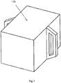
Fig. 1 is a schematic view showing a whole structure of a handheld backscatter imager according to an embodiment of the present disclosure; -
Fig. 2 is a schematic view showing structures of main internal components of the handheld backscatter imager shown inFig. 1 ; -
Fig. 3 is a schematic view showing a structure of a modulator of the handheld backscatter imager shown inFig. 1 ; -
Fig. 4a is a schematic view showing a structure of the modulator shown inFig. 3 , in a configuration of slot; -
Fig. 4b is a schematic view showing a structure of the modulator shown inFig. 3 , in a configuration of apertures; -
Fig. 4c is a schematic view showing a structure of the modulator shown inFig. 3 , in another configuration of slot; and -
Fig. 4d is a schematic view showing a structure of the modulator shown inFig. 3 , in another configuration of apertures. - 100 - handheld backscatter imager, 1 - X-ray source, 2 - collimator, 3 - modulator, 30 - passing region, 31 - long and narrow slot, 32 - long and narrow column of apertures, 310 - "short tail" slot, 320 - smaller-diameter aperture, 4 - detector, 5 - electric motor, and, 6 - controller.
- Specific embodiments of the present disclosure will be described hereinafter in detail, and examples of the specific embodiments are illustrated in the attached drawings, wherein the like reference numerals refer to the like or similar elements throughout the drawings. The specific embodiments described hereinafter with reference to the attached drawings are examples and are intended to explain and illustrate the present disclosure, but not to be interpreted as a limitation to the present disclosure.
- The present disclosure provides a handheld backscatter imager and an imaging method thereof.
- Referring to
Figs. 1-3 , ahandheld backscatter imager 100 according to the present disclosure mainly comprises: anX-ray source 1, a collimator 2, amodulator 3, a detector 4, anelectric motor 5 and acontroller 6. - The
X-ray source 1 is a device that generates an X-ray. TheX-ray source 1 is usually an X-ray machine. - The collimator 2 is configured to constrain a ray emitted by the
X-ray source 1 into a fan-beam. The collimator 2 is made of an X-ray shielding material, such as lead, tungsten, copper, steel, lead oxide, tungsten oxide, or the like, with adequate thickness, or a mixture of some of them. The collimator 2 is formed with a collimating slit having a certain width, so that the X-ray can pass through the collimating slit freely, forming a fan-beam. - The
modulator 3 is a device that forms a spatially modulated beam. Themodulator 3 generally assumes a circular ring shape, and an X-ray passing region 30 (which is a blank region allowing the X-ray to pass therethrough freely and having a certain geometric shape) is formed in the ring and is configured for allowing the X-ray beam corresponding in actual size to more than one pixel point for an image to pass therethrough freely. Themodulator 3 is made of an X-ray shielding material, such as lead, tungsten, copper, steel, lead oxide, tungsten oxide, or the like, with adequate thickness, or a mixture of some of them. TheX-ray passing region 30 is formed in the circular ring of themodulator 3. Themodulator 3 may rotate, and has its rotating axis perpendicular to a plane of the fan-beam. - The passing
region 30 is a blank region opened in the shielding material and allowing the X-ray to pass therethrough freely and having a certain geometric shape. For example, the passingregion 30 may consist ofseveral slots 31 having certain lengths and uniform diameters, and a length-width ratio of eachslot 31 is determined according to actual requirements and ranges from 2:1 to 50:1, its length direction is consistent with a linear speed direction of rotation of the ring; for another example, the passingregion 30 may consist of several sets ofapertures 32 closely adjacent to one another, and the number of each set ofapertures 32 can range from 2 to 50, and an arrangement direction of theapertures 32 is consistent with the linear speed direction of rotation of the ring. - The fan-beam forms a ray beam flow with predefined certain shape, after passing through the collimator 2 and then through the passing
region 30 of the modulator. When themodulator 3 rotates, the ray beam flow can change continuously spatially, that is, a spatial modulation is achieved. - Traditional "flying-spot" scanning is to form a spatially modulated beam flow of a "spot", while according to the present disclosure, a spatially modulated beam flow of a "line" is formed, and thus it is called "flying line" scanning.
- Because several beam flows of "spot" are provided in the "flying-line" mode at a time, the output dosage in the "flying-line" mode is several times more than that in the "flying-spot" scanning mode, and the increase of dosage is helpful fundamentally to reduce random fluctuation of signal and to improve signal-to-noise ratio of the signal.
- The detector 4 receives the X-ray, scattered by an object to be inspected and generates a scattering signal. For example, the detector 4 absorbs the ray, scattered by an object to be inspected, from the "flying-line" beam flow, and further converts it into a digital signal to be processed according to rotation angle of the
modulator 3. - The
electric motor 5 is configured to provide power, for example for driving themodulator 3 to rotate with a certain angular speed. - The
controller 6 controls rotation of themodulator 3, and acquires angular information of themodulator 3 and the scattering signal of the detector 4. For example, thecontroller 6 directly controls theelectric motor 5 to control angular speed of rotation, while acquiring angular information of themodulator 3 and the scattering signal of the detector 4. - In the
handheld backscatter imager 100 according to the present disclosure, the "flying-line" equals several "flying-spots" incident on the object to be inspected at the same time, accordingly, the manner in which scanning positions and scattering signals are in a simple one-to-one correspondence in the traditional "flying-spot" scanning mode does not apply in "flying-line" mode obviously. It is necessary to decompose actual signal of each position in signals. The imaging method is provided as follows: - by means of the modulator, the X-ray beam corresponding in actual size to more than one pixel point is emitted, (in the traditional "flying-spot" scanning, a size of a pencil beam flow through a flying-spot modulation device is an actual size of one pixel point of an image);
- detector signals acquired at each time represent a sum of a plurality of pixel points of an image; by an imaging algorithm, value of each of the pixel points of the image is decomposed from the detector signals.
- In the imaging method of the
handheld backscatter imager 100 according to the present disclosure, a final scanning image is achieved by computing, according to the imaging algorithm, the angular information and the scattering signals acquired. For example, the imaging algorithm operates in thecontroller 6, and the final scanning image is achieved by computing, according to the successive differential algorithm, the angular information and the scattering signals acquired. Specifically, thecontroller 6 calculates, based on a successive differential algorithm, a difference value between a currently acquired scattering signal and a formerly acquired scattering signal; calculates, based on currently acquired angular information, spatially angular information of emission of a current X-ray beam, and determines a position of the pixel point, corresponding to the current X-ray beam and being in the imaging image, and a corresponding compensation value according to the spatially angular information; and determines, based on the difference value and the corresponding compensation value, a pixel point value at the position of the pixel point corresponding to the current X-ray beam; so as to obtain a final scanning image. - According to the
handheld backscatter imager 100 and the imaging method of the handheld backscatter imager according to the present disclosure, the embodiments about configurations of theX-ray passing region 30 in themodulator 3 and the algorithms of values of the pixel points in the imaging method are presented as follows. - The
X-ray passing region 30 in themodulator 3 is designed to have the configuration of a slot. - A length-width ratio of a collimating slit in the collimator 2 is n and a length-width ratio of the passing
region 30 is m, 2 ≤ m < n/2 (when m = 1, it is a conventional flying-spot scanning mode with formation of a square hole), that is to say, the number of spots in each scanning line is n, a maximum spot number being covered by the flying-line is m, and i is the number of imaging pixel points corresponding to a single X-ray beam. - Once the
modulator 3 rotates, signals acquired by thedetector 3 are S1, S2, ......, Sn, started from when theslot 31 just enters a range of the collimating slit, and values of the pixel points for displaying in the final scanning image are P1, P2, ......, Pn, then, calculation formulas of the values of the pixel points are as follows:
- The
X-ray passing region 30 in themodulator 3 is designed to have a configuration of apertures. - A length-width ratio of a collimating slit in the collimator 2 is n, the passing
region 30 is designed to have a long and narrow column of a series ofapertures 32, wherein the number of the apertures is m (when m = 1, it is a conventional flying-spot scanning mode with formation of a circular hole), that is to say, the number of spots in each scanning line is n, a maximum spot number being covered by the flying-line is m, and i is the number of imaging pixel points corresponding to a single X-ray beam. - Once the
modulator 3 rotates, signals acquired by thedetector 3 are S1, S2, ......, Sn, started from when theapertures 32 just enter a range of the collimating slit, and values of the pixel points for displaying in the final scanning image are P1, P2, ......, Pn, then, calculation formulas of the values of the pixel points are as follows:
- The
X-ray passing region 30 in themodulator 3 is designed to have another configuration of a slot. - A length-width ratio of a collimating slit in the collimator 2 is n, the passing
region 30 is designed to have aslot 31, with a "short tail" slot 310 (that is, with a smaller diameter end 310) at its end in a counter-rotation direction, a length of the "short tail"slot 310 equals to a width of theslot 31 while a width of the "short tail"slot 310 is less than the width of theslot 31, with a ratio coefficient of α (α < 1). A length-width ratio of theslot 31 together with the "short tail"slot 310 is m, 2 ≤ m < n/2, that is to say, the number of spots in each scanning line is n, a maximum spot number being covered by the flying-line is m, and i is the number of imaging pixel points corresponding to a single X-ray beam. - Once the
modulator 3 rotates, signals acquired by thedetector 3 are S1, S2, ......, Sn, started from when theslot 31 just enters a range of the collimating slit, and values of the pixel points for displaying in the final scanning image are P1, P2, ......, Pn, then, calculation formulas of the values of the pixel points are as follows:
- This configuration can rapidly reduce influence of former signals on later signals, achieving better image effect.
- The
X-ray passing region 30 in themodulator 3 is designed to have another configuration of apertures. - A length-width ratio of a collimating slit in the collimator 2 is n, the passing
region 30 is designed to have a series ofapertures 32 connected to one another and including a smaller-diameter aperture 320, wherein a diameter of the smaller-diameter aperture 320 is less than that ofnormal apertures 32, and a ratio coefficient of α (α < 1). The total number of the long and narrow column ofapertures 32 together with the smaller-diameter aperture 320 is m, 2 ≤ m < n/2, that is to say, the number of spots in each scanning line is n, a maximum spot number being covered by the flying-line is m, and i is the number of imaging pixel points corresponding to a single X-ray beam. - Once the
modulator 3 rotates, signals acquired by thedetector 3 are S1, S2, ......, Sn, started from when the column ofapertures 32 just enters a range of the collimating slit, and values of the pixel points for displaying in a final scanning image are P1, P2, ......, Pn, then, calculation formulas of the values of the pixel points are as follows:
- This configuration can rapidly reduce influence of former signals on later signals, achieving better image effect.
- Thus it can be seen from the above that, with the handheld backscatter imager and the imaging method of the handheld backscatter imager according to the present disclosure, by the "flying-line" scanning mode, the output dosage of the X-ray machine is greatly increased actually, while maintaining the scanning time unchanged. Because the object to be scanned is goods instead of a human being, a great output dosage will not cause a risk on radiation safety of the object to be inspected.
- Meanwhile, the output dosage in the "flying-line" scanning mode is several times more than that in the "flying-spot" scanning mode, and the increase of dosage is helpful fundamentally to reduce random fluctuation of signal and to improve signal-to-noise ratio of the signal.
- The above specific embodiments of the present disclosure merely exemplarily explain principles and advantages of the present disclosure, but not to limit the present disclosure. It would be appreciated by those skilled in the art that any changes and modifications made on the present disclosure without departing from the principles and spirit of the present disclosure fall into the scope of the present disclosure, the scope of which is defined in the claims.
Claims (20)
- A handheld backscatter imager, characterized in that, the handheld backscatter imager comprises:an X-ray source, configured for generating an X-ray;at least one collimator, configured for collimation of the X-ray;a modulator, configured to surround the X-ray source and capable of rotating around the X-ray source, the modulator being formed with at least one X-ray passing region that allows an X-ray beam corresponding to more than one pixel point for an imaging image to pass therethrough;a detector, configured to receive a scattered X-ray, which is generated after the X-ray beam modulated by the modulator is scattered by an object to be inspected, and to generate a corresponding scattering signal; anda controller, configured to acquire angular information of the X-ray passing region and the scattering signal of the detector.
- The handheld backscatter imager of claim 1, characterized in that, the controller is further configured to:calculate, based on a successive differential algorithm, a difference value between a currently acquired scattering signal and a formerly acquired scattering signal;calculate, based on currently acquired angular information, spatially angular information of emission of a current X-ray beam;determine a position of the pixel point, corresponding to the current X-ray beam, in the imaging image, and a corresponding compensation value according to the spatially angular information; anddetermine, based on the difference value and the corresponding compensation value, a pixel point value at the position of the pixel point corresponding to the current X-ray beam, so as to obtain a final scanning image.
- The handheld backscatter imager of claim 1, characterized in that, the controller is further configured to control rotation of the modulator.
- The handheld backscatter imager of any one of claims 1-3, characterized in that,
the modulator assumes a circular ring shape having a central axis of the X-ray source as its axis, and the at least one X-ray passing region is formed in a ring surface of the circular ring shape. - The handheld backscatter imager of claim 4, characterized in that, the at least one collimator corresponds to the at least one X-ray passing region, the collimator assumes a sector shape and is provided between the corresponding X-ray passing region of the modulator and the X-ray source, and the corresponding X-ray passing region is designed to be perpendicular to a sector-shaped surface of the collimator.
- The handheld backscatter imager of claim 5, characterized in that, the at least one X-ray passing region is designed to have a long and narrow slot configuration.
- The handheld backscatter imager of claim 5, characterized in that, the at least one X-ray passing region is designed to have a configuration of a long and narrow column of apertures, formed by a series of apertures connected to one another.
- The handheld backscatter imager of claim 5, characterized in that, the at least one X-ray passing region is designed to have a configuration of a long and narrow slot with a smaller diameter end.
- The handheld backscatter imager of claim 5, characterized in that, the at least one X-ray passing region is designed to have a configuration of a long and narrow column of apertures, formed by a series of apertures connected to one another and including a smaller-diameter aperture.
- A handheld backscatter imaging method, characterized in that, the imaging method comprises:generating, by an X-ray source, an X-ray;collimating, by a collimator, the X-ray;passing an X-ray beam corresponding to more than one pixel point through at least one X-ray passing region of the modulator, the modulator being configured to surround the X-ray source and be capable of rotating around the X-ray source, the modulator being formed with the at least one X-ray passing region;receiving, by a detector, a scattered X-ray, which is generated after the X-ray beam modulated by the modulator is scattered by an object to be inspected, and generating a corresponding scattering signal by the detector; andacquiring, by a controller, angular information of the modulator and the scattering signal of the detector.
- The imaging method of claim 10, characterized in that, the controller is configured to:calculate, based on a successive differential algorithm, a difference value between a currently acquired scattering signal and a formerly acquired scattering signal;calculate, based on currently acquired angular information, spatially angular information of emission of a current X-ray beam;determine a position of the pixel point, corresponding to the current X-ray beam, in the imaging image, and a corresponding compensation value according to the spatially angular information; anddetermine, based on the difference value and the corresponding compensation value, a pixel point value at the position of the pixel point corresponding to the current X-ray beam, so as to obtain a final scanning image.
- The imaging method of claim 11, characterized in that, the controller is further configured to control rotation of the modulator.
- The imaging method of claim 12, characterized in that, the at least one X-ray passing region is designed to have a long and narrow slot configuration.
- The imaging method of claim 13, characterized in that,
if a length-width ratio of a collimating slit in the collimator is n and a length-width ratio of the at least one X-ray passing region is m, 2 ≤ m < n/2, and, i is the number of imaging pixel points corresponding to a single X-ray beam, signals acquired by the detector are S1, S2, ......, Sn, started from when the at least one X-ray passing region just enters a range of the collimating slit, and values of the pixel points for displaying in the final scanning image are P1, P2, ......, Pn, then, calculation formulas of the values of the pixel points are as follows:
- The imaging method of claim 12, characterized in that, the at least one X-ray passing region is designed to have a configuration of a long and narrow column of apertures, formed by a series of apertures connected to one another.
- The imaging method of claim 15, characterized in that,
if a length-width ratio of a collimating slit in the collimator is n and a length-width ratio of the at least one X-ray passing region is m, 2 ≤ m < n/2, and, i is the number of imaging pixel points corresponding to a single X-ray beam, signals acquired by the detector are S1, S2, ......, Sn, started from when the at least one X-ray passing region just enters a range of the collimating slit, and values of the pixel points for displaying in the final scanning image are P1, P2, ......, Pn, then, calculation formulas of the values of the pixel points are as follows:
- The imaging method of claim 12, characterized in that, the at least one X-ray passing region is designed to have a configuration of a long and narrow slot with a smaller diameter end.
- The imaging method of claim 17, characterized in that,
if a length-width ratio of a collimating slit in the collimator is n and a length-width ratio of the at least one X-ray passing region is m, 2 ≤ m < n/2, a length-width ratio coefficient of the smaller diameter end is a, and, i is the number of imaging pixel points corresponding to a single X-ray beam, signals acquired by the detector are S1, S2, ......, Sn, started from when the at least one X-ray passing region just enters a range of the collimating slit, and values of the pixel points for displaying in the final scanning image are P1, P2, ......, Pn, then, calculation formulas of the values of the pixel points are as follows:
- The imaging method of claim 12, characterized in that, the at least one X-ray passing region is designed to have a configuration of a long and narrow column of apertures, formed by a series of apertures connected to one another and including a smaller-diameter aperture.
- The imaging method of claim 19, characterized in that,
if a length-width ratio of a collimating slit in the collimator is n and a length-width ratio of the at least one X-ray passing region is m, 2 ≤ m < n/2, a diameter ratio coefficient between the smaller-diameter aperture and a normal-diameter aperture is a, and, i is the number of imaging pixel points corresponding to a single X-ray beam, signals acquired by the detector are S1, S2, , Sn, started from when the at least one X-ray passing region just enters a range of the collimating slit, and values of the pixel points for displaying in a final scanning image are P1, P2, ......, Pn, then, calculation formulas of the values of the pixel points are as follows:
Applications Claiming Priority (2)
| Application Number | Priority Date | Filing Date | Title |
|---|---|---|---|
| CN201511009171.1A CN105445303B (en) | 2015-12-29 | 2015-12-29 | Hand-held back scattering imaging instrument and its imaging method |
| PCT/CN2016/096654 WO2017113831A1 (en) | 2015-12-29 | 2016-08-25 | Handheld backscatter imager and imaging method thereof |
Publications (3)
| Publication Number | Publication Date |
|---|---|
| EP3399303A1 true EP3399303A1 (en) | 2018-11-07 |
| EP3399303A4 EP3399303A4 (en) | 2019-01-23 |
| EP3399303B1 EP3399303B1 (en) | 2021-04-28 |
Family
ID=55555748
Family Applications (1)
| Application Number | Title | Priority Date | Filing Date |
|---|---|---|---|
| EP16880624.8A Active EP3399303B1 (en) | 2015-12-29 | 2016-08-25 | Handheld backscatter imager and imaging method thereof |
Country Status (4)
| Country | Link |
|---|---|
| EP (1) | EP3399303B1 (en) |
| CN (1) | CN105445303B (en) |
| BR (1) | BR112017025704B1 (en) |
| WO (1) | WO2017113831A1 (en) |
Cited By (2)
| Publication number | Priority date | Publication date | Assignee | Title |
|---|---|---|---|---|
| US20240013947A1 (en) * | 2022-07-07 | 2024-01-11 | Viken Detection Corporation | Rotating Hoop Chopper Wheel for X-Ray Imagers |
| US12347582B2 (en) | 2014-11-20 | 2025-07-01 | Viken Detection Corporation | X-ray scanning system |
Families Citing this family (8)
| Publication number | Priority date | Publication date | Assignee | Title |
|---|---|---|---|---|
| CN105445303B (en) * | 2015-12-29 | 2019-02-19 | 清华大学 | Hand-held back scattering imaging instrument and its imaging method |
| CN109142404B (en) * | 2018-11-01 | 2024-06-11 | 同方威视技术股份有限公司 | Backscatter imaging system, scanning inspection system and backscatter imaging method |
| CN109471186A (en) * | 2018-12-18 | 2019-03-15 | 东莞深圳清华大学研究院创新中心 | A flying spot scanning security checker and its scanning method |
| US11683879B2 (en) * | 2020-06-09 | 2023-06-20 | Moxtek, Inc. | Scanning x-ray system |
| CN114166875B (en) * | 2020-09-11 | 2024-01-12 | 同方威视技术股份有限公司 | Backscatter inspection system |
| CN113552643A (en) * | 2021-09-06 | 2021-10-26 | 山东医工健康科技有限公司 | Flying spot scanning device for X-ray source |
| CN119290936B (en) * | 2024-12-12 | 2025-04-22 | 杭州睿影科技有限公司 | Back scattering detection device, imaging method, imaging equipment and storage medium |
| CN120559001B (en) * | 2025-06-20 | 2026-03-03 | 中北大学 | Backscatter imaging device and line scan imaging method |
Family Cites Families (13)
| Publication number | Priority date | Publication date | Assignee | Title |
|---|---|---|---|---|
| CN1107882C (en) * | 1999-08-25 | 2003-05-07 | 沈阳师范学院 | Multifunctional industrial X-ray imaging system |
| WO2006116100A1 (en) * | 2005-04-22 | 2006-11-02 | American Science And Engineering, Inc. | X-ray backscatter inspection with coincident optical beam |
| CN102565110B (en) * | 2010-12-31 | 2015-04-01 | 同方威视技术股份有限公司 | A scanning device and method for a ray beam for backscattered imaging |
| US9151721B2 (en) * | 2011-06-20 | 2015-10-06 | The Boeing Company | Integrated backscatter X-ray system |
| CN202177591U (en) * | 2011-07-07 | 2012-03-28 | 董明 | X-ray rotating disk type breaker flying spot forming device |
| CN103063691B (en) * | 2011-10-18 | 2014-11-12 | 北京睿思厚德辐射信息科技开发有限公司 | Double-flying line multi-slit scanning backscatter planar imaging, stereoscopic imaging and self-scanning imaging device |
| WO2013112819A1 (en) * | 2012-01-27 | 2013-08-01 | American Science And Engineering, Inc. | Hand-held x-ray backscatter imaging device |
| FR3000211B1 (en) * | 2012-12-20 | 2015-12-11 | Commissariat Energie Atomique | SCANNING LIGHTING DEVICE, IMAGING DEVICE COMPRISING SAME, AND METHOD FOR OPERATING SAME |
| CN103901064B (en) * | 2012-12-27 | 2017-05-10 | 清华大学 | Ray emission device, imaging system and inspection method |
| US9020103B2 (en) * | 2013-02-15 | 2015-04-28 | American Science And Engineering, Inc. | Versatile beam scanner with fan beam |
| US9204848B2 (en) * | 2015-01-26 | 2015-12-08 | Martin Annis Patent Trust—2009 | Low-dose X-ray backscatter system for three dimensional medical imaging using a conventional X-ray tube |
| CN205484137U (en) * | 2015-12-29 | 2016-08-17 | 清华大学 | Hand -held type back scattering imaging appearance |
| CN105445303B (en) * | 2015-12-29 | 2019-02-19 | 清华大学 | Hand-held back scattering imaging instrument and its imaging method |
-
2015
- 2015-12-29 CN CN201511009171.1A patent/CN105445303B/en active Active
-
2016
- 2016-08-25 BR BR112017025704-1A patent/BR112017025704B1/en active IP Right Grant
- 2016-08-25 EP EP16880624.8A patent/EP3399303B1/en active Active
- 2016-08-25 WO PCT/CN2016/096654 patent/WO2017113831A1/en not_active Ceased
Cited By (4)
| Publication number | Priority date | Publication date | Assignee | Title |
|---|---|---|---|---|
| US12347582B2 (en) | 2014-11-20 | 2025-07-01 | Viken Detection Corporation | X-ray scanning system |
| US20240013947A1 (en) * | 2022-07-07 | 2024-01-11 | Viken Detection Corporation | Rotating Hoop Chopper Wheel for X-Ray Imagers |
| WO2024011247A3 (en) * | 2022-07-07 | 2024-02-15 | Viken Detection Corporation | Rotating hoop chopper wheel for x-ray imagers |
| US12125605B2 (en) | 2022-07-07 | 2024-10-22 | Viken Detection Corporation | Rotating hoop chopper wheel for x-ray imagers |
Also Published As
| Publication number | Publication date |
|---|---|
| CN105445303B (en) | 2019-02-19 |
| EP3399303B1 (en) | 2021-04-28 |
| BR112017025704A2 (en) | 2018-08-07 |
| CN105445303A (en) | 2016-03-30 |
| WO2017113831A1 (en) | 2017-07-06 |
| EP3399303A4 (en) | 2019-01-23 |
| BR112017025704B1 (en) | 2023-04-18 |
Similar Documents
| Publication | Publication Date | Title |
|---|---|---|
| EP3399303B1 (en) | Handheld backscatter imager and imaging method thereof | |
| US20230204812A1 (en) | Hand-Held Portable Backscatter Inspection System | |
| EP2755557B1 (en) | Forward- and variable-offset hoop for beam scanning | |
| EP2963455B1 (en) | X-ray backscattering safety inspection system having distributed x-ray source and method using the same | |
| US8116426B2 (en) | Computed tomography device and method using circular-pixel position-adaptive interpolation | |
| KR102033233B1 (en) | Multi modal detection system and method | |
| JPS6411296B2 (en) | ||
| US11914045B2 (en) | LiDAR and storage medium | |
| AU2017265073B2 (en) | Inspection devices, inspection methods and inspection systems | |
| MX2012009013A (en) | Scanning systems. | |
| WO2017101471A1 (en) | Liquid assay method and system | |
| US20230290533A1 (en) | X-Ray Scanning with Variable Resolution | |
| JP2005296653A (en) | Computer tomography image forming method and computer tomography apparatus using computer tomography apparatus | |
| CN204129240U (en) | X ray backscattered channel formula safe examination system | |
| US20220091051A1 (en) | Multi-channel static ct device | |
| CN113834834B (en) | Backscatter imaging device and backscatter detection system | |
| US8724872B1 (en) | Single radiation data from multiple radiation sources | |
| WO2025098079A1 (en) | Ct scanning imaging system and method based on single linear scanning channel | |
| CN110146524B (en) | CT scanning and reconstruction method based on inverse Compton scattering source and imaging system | |
| CN119575496A (en) | Radiation inspection system | |
| WO2014092073A1 (en) | Method and device for measuring scattering intensity distribution | |
| CN205484137U (en) | Hand -held type back scattering imaging appearance | |
| CN216449466U (en) | Back scattering imaging device and back scattering detection system | |
| JP2011232226A (en) | X-ray generator and x-ray inspection device | |
| CN108078580B (en) | Radiographic method and system therefor |
Legal Events
| Date | Code | Title | Description |
|---|---|---|---|
| STAA | Information on the status of an ep patent application or granted ep patent |
Free format text: STATUS: THE INTERNATIONAL PUBLICATION HAS BEEN MADE |
|
| PUAI | Public reference made under article 153(3) epc to a published international application that has entered the european phase |
Free format text: ORIGINAL CODE: 0009012 |
|
| STAA | Information on the status of an ep patent application or granted ep patent |
Free format text: STATUS: REQUEST FOR EXAMINATION WAS MADE |
|
| 17P | Request for examination filed |
Effective date: 20171130 |
|
| AK | Designated contracting states |
Kind code of ref document: A1 Designated state(s): AL AT BE BG CH CY CZ DE DK EE ES FI FR GB GR HR HU IE IS IT LI LT LU LV MC MK MT NL NO PL PT RO RS SE SI SK SM TR |
|
| AX | Request for extension of the european patent |
Extension state: BA ME |
|
| A4 | Supplementary search report drawn up and despatched |
Effective date: 20181221 |
|
| RIC1 | Information provided on ipc code assigned before grant |
Ipc: G01N 23/203 20060101AFI20181217BHEP Ipc: G01T 7/00 20060101ALI20181217BHEP Ipc: G01V 5/00 20060101ALI20181217BHEP |
|
| DAV | Request for validation of the european patent (deleted) | ||
| DAX | Request for extension of the european patent (deleted) | ||
| STAA | Information on the status of an ep patent application or granted ep patent |
Free format text: STATUS: EXAMINATION IS IN PROGRESS |
|
| 17Q | First examination report despatched |
Effective date: 20200305 |
|
| GRAP | Despatch of communication of intention to grant a patent |
Free format text: ORIGINAL CODE: EPIDOSNIGR1 |
|
| STAA | Information on the status of an ep patent application or granted ep patent |
Free format text: STATUS: GRANT OF PATENT IS INTENDED |
|
| INTG | Intention to grant announced |
Effective date: 20201120 |
|
| GRAS | Grant fee paid |
Free format text: ORIGINAL CODE: EPIDOSNIGR3 |
|
| GRAA | (expected) grant |
Free format text: ORIGINAL CODE: 0009210 |
|
| STAA | Information on the status of an ep patent application or granted ep patent |
Free format text: STATUS: THE PATENT HAS BEEN GRANTED |
|
| AK | Designated contracting states |
Kind code of ref document: B1 Designated state(s): AL AT BE BG CH CY CZ DE DK EE ES FI FR GB GR HR HU IE IS IT LI LT LU LV MC MK MT NL NO PL PT RO RS SE SI SK SM TR |
|
| REG | Reference to a national code |
Ref country code: GB Ref legal event code: FG4D |
|
| REG | Reference to a national code |
Ref country code: CH Ref legal event code: EP |
|
| REG | Reference to a national code |
Ref country code: AT Ref legal event code: REF Ref document number: 1387621 Country of ref document: AT Kind code of ref document: T Effective date: 20210515 |
|
| REG | Reference to a national code |
Ref country code: DE Ref legal event code: R096 Ref document number: 602016057136 Country of ref document: DE |
|
| REG | Reference to a national code |
Ref country code: IE Ref legal event code: FG4D |
|
| REG | Reference to a national code |
Ref country code: LT Ref legal event code: MG9D |
|
| REG | Reference to a national code |
Ref country code: AT Ref legal event code: MK05 Ref document number: 1387621 Country of ref document: AT Kind code of ref document: T Effective date: 20210428 |
|
| PG25 | Lapsed in a contracting state [announced via postgrant information from national office to epo] |
Ref country code: HR Free format text: LAPSE BECAUSE OF FAILURE TO SUBMIT A TRANSLATION OF THE DESCRIPTION OR TO PAY THE FEE WITHIN THE PRESCRIBED TIME-LIMIT Effective date: 20210428 Ref country code: AT Free format text: LAPSE BECAUSE OF FAILURE TO SUBMIT A TRANSLATION OF THE DESCRIPTION OR TO PAY THE FEE WITHIN THE PRESCRIBED TIME-LIMIT Effective date: 20210428 Ref country code: BG Free format text: LAPSE BECAUSE OF FAILURE TO SUBMIT A TRANSLATION OF THE DESCRIPTION OR TO PAY THE FEE WITHIN THE PRESCRIBED TIME-LIMIT Effective date: 20210728 Ref country code: NL Free format text: LAPSE BECAUSE OF FAILURE TO SUBMIT A TRANSLATION OF THE DESCRIPTION OR TO PAY THE FEE WITHIN THE PRESCRIBED TIME-LIMIT Effective date: 20210428 Ref country code: FI Free format text: LAPSE BECAUSE OF FAILURE TO SUBMIT A TRANSLATION OF THE DESCRIPTION OR TO PAY THE FEE WITHIN THE PRESCRIBED TIME-LIMIT Effective date: 20210428 Ref country code: LT Free format text: LAPSE BECAUSE OF FAILURE TO SUBMIT A TRANSLATION OF THE DESCRIPTION OR TO PAY THE FEE WITHIN THE PRESCRIBED TIME-LIMIT Effective date: 20210428 |
|
| PG25 | Lapsed in a contracting state [announced via postgrant information from national office to epo] |
Ref country code: GR Free format text: LAPSE BECAUSE OF FAILURE TO SUBMIT A TRANSLATION OF THE DESCRIPTION OR TO PAY THE FEE WITHIN THE PRESCRIBED TIME-LIMIT Effective date: 20210729 Ref country code: IS Free format text: LAPSE BECAUSE OF FAILURE TO SUBMIT A TRANSLATION OF THE DESCRIPTION OR TO PAY THE FEE WITHIN THE PRESCRIBED TIME-LIMIT Effective date: 20210828 Ref country code: LV Free format text: LAPSE BECAUSE OF FAILURE TO SUBMIT A TRANSLATION OF THE DESCRIPTION OR TO PAY THE FEE WITHIN THE PRESCRIBED TIME-LIMIT Effective date: 20210428 Ref country code: NO Free format text: LAPSE BECAUSE OF FAILURE TO SUBMIT A TRANSLATION OF THE DESCRIPTION OR TO PAY THE FEE WITHIN THE PRESCRIBED TIME-LIMIT Effective date: 20210728 Ref country code: PL Free format text: LAPSE BECAUSE OF FAILURE TO SUBMIT A TRANSLATION OF THE DESCRIPTION OR TO PAY THE FEE WITHIN THE PRESCRIBED TIME-LIMIT Effective date: 20210428 Ref country code: PT Free format text: LAPSE BECAUSE OF FAILURE TO SUBMIT A TRANSLATION OF THE DESCRIPTION OR TO PAY THE FEE WITHIN THE PRESCRIBED TIME-LIMIT Effective date: 20210830 Ref country code: RS Free format text: LAPSE BECAUSE OF FAILURE TO SUBMIT A TRANSLATION OF THE DESCRIPTION OR TO PAY THE FEE WITHIN THE PRESCRIBED TIME-LIMIT Effective date: 20210428 Ref country code: SE Free format text: LAPSE BECAUSE OF FAILURE TO SUBMIT A TRANSLATION OF THE DESCRIPTION OR TO PAY THE FEE WITHIN THE PRESCRIBED TIME-LIMIT Effective date: 20210428 |
|
| REG | Reference to a national code |
Ref country code: NL Ref legal event code: MP Effective date: 20210428 |
|
| PG25 | Lapsed in a contracting state [announced via postgrant information from national office to epo] |
Ref country code: SK Free format text: LAPSE BECAUSE OF FAILURE TO SUBMIT A TRANSLATION OF THE DESCRIPTION OR TO PAY THE FEE WITHIN THE PRESCRIBED TIME-LIMIT Effective date: 20210428 Ref country code: SM Free format text: LAPSE BECAUSE OF FAILURE TO SUBMIT A TRANSLATION OF THE DESCRIPTION OR TO PAY THE FEE WITHIN THE PRESCRIBED TIME-LIMIT Effective date: 20210428 Ref country code: CZ Free format text: LAPSE BECAUSE OF FAILURE TO SUBMIT A TRANSLATION OF THE DESCRIPTION OR TO PAY THE FEE WITHIN THE PRESCRIBED TIME-LIMIT Effective date: 20210428 Ref country code: EE Free format text: LAPSE BECAUSE OF FAILURE TO SUBMIT A TRANSLATION OF THE DESCRIPTION OR TO PAY THE FEE WITHIN THE PRESCRIBED TIME-LIMIT Effective date: 20210428 Ref country code: DK Free format text: LAPSE BECAUSE OF FAILURE TO SUBMIT A TRANSLATION OF THE DESCRIPTION OR TO PAY THE FEE WITHIN THE PRESCRIBED TIME-LIMIT Effective date: 20210428 Ref country code: RO Free format text: LAPSE BECAUSE OF FAILURE TO SUBMIT A TRANSLATION OF THE DESCRIPTION OR TO PAY THE FEE WITHIN THE PRESCRIBED TIME-LIMIT Effective date: 20210428 Ref country code: ES Free format text: LAPSE BECAUSE OF FAILURE TO SUBMIT A TRANSLATION OF THE DESCRIPTION OR TO PAY THE FEE WITHIN THE PRESCRIBED TIME-LIMIT Effective date: 20210428 |
|
| REG | Reference to a national code |
Ref country code: DE Ref legal event code: R097 Ref document number: 602016057136 Country of ref document: DE |
|
| REG | Reference to a national code |
Ref country code: DE Ref legal event code: R119 Ref document number: 602016057136 Country of ref document: DE |
|
| PLBE | No opposition filed within time limit |
Free format text: ORIGINAL CODE: 0009261 |
|
| STAA | Information on the status of an ep patent application or granted ep patent |
Free format text: STATUS: NO OPPOSITION FILED WITHIN TIME LIMIT |
|
| REG | Reference to a national code |
Ref country code: CH Ref legal event code: PL |
|
| PG25 | Lapsed in a contracting state [announced via postgrant information from national office to epo] |
Ref country code: MC Free format text: LAPSE BECAUSE OF FAILURE TO SUBMIT A TRANSLATION OF THE DESCRIPTION OR TO PAY THE FEE WITHIN THE PRESCRIBED TIME-LIMIT Effective date: 20210428 |
|
| 26N | No opposition filed |
Effective date: 20220131 |
|
| REG | Reference to a national code |
Ref country code: BE Ref legal event code: MM Effective date: 20210831 |
|
| GBPC | Gb: european patent ceased through non-payment of renewal fee |
Effective date: 20210825 |
|
| PG25 | Lapsed in a contracting state [announced via postgrant information from national office to epo] |
Ref country code: LI Free format text: LAPSE BECAUSE OF NON-PAYMENT OF DUE FEES Effective date: 20210831 Ref country code: CH Free format text: LAPSE BECAUSE OF NON-PAYMENT OF DUE FEES Effective date: 20210831 |
|
| PG25 | Lapsed in a contracting state [announced via postgrant information from national office to epo] |
Ref country code: IS Free format text: LAPSE BECAUSE OF FAILURE TO SUBMIT A TRANSLATION OF THE DESCRIPTION OR TO PAY THE FEE WITHIN THE PRESCRIBED TIME-LIMIT Effective date: 20210828 Ref country code: LU Free format text: LAPSE BECAUSE OF NON-PAYMENT OF DUE FEES Effective date: 20210825 Ref country code: AL Free format text: LAPSE BECAUSE OF FAILURE TO SUBMIT A TRANSLATION OF THE DESCRIPTION OR TO PAY THE FEE WITHIN THE PRESCRIBED TIME-LIMIT Effective date: 20210428 |
|
| PG25 | Lapsed in a contracting state [announced via postgrant information from national office to epo] |
Ref country code: IT Free format text: LAPSE BECAUSE OF FAILURE TO SUBMIT A TRANSLATION OF THE DESCRIPTION OR TO PAY THE FEE WITHIN THE PRESCRIBED TIME-LIMIT Effective date: 20210428 Ref country code: IE Free format text: LAPSE BECAUSE OF NON-PAYMENT OF DUE FEES Effective date: 20210825 Ref country code: GB Free format text: LAPSE BECAUSE OF NON-PAYMENT OF DUE FEES Effective date: 20210825 Ref country code: FR Free format text: LAPSE BECAUSE OF NON-PAYMENT OF DUE FEES Effective date: 20210831 Ref country code: DE Free format text: LAPSE BECAUSE OF NON-PAYMENT OF DUE FEES Effective date: 20220301 Ref country code: BE Free format text: LAPSE BECAUSE OF NON-PAYMENT OF DUE FEES Effective date: 20210831 |
|
| PG25 | Lapsed in a contracting state [announced via postgrant information from national office to epo] |
Ref country code: CY Free format text: LAPSE BECAUSE OF FAILURE TO SUBMIT A TRANSLATION OF THE DESCRIPTION OR TO PAY THE FEE WITHIN THE PRESCRIBED TIME-LIMIT Effective date: 20210428 |
|
| PG25 | Lapsed in a contracting state [announced via postgrant information from national office to epo] |
Ref country code: HU Free format text: LAPSE BECAUSE OF FAILURE TO SUBMIT A TRANSLATION OF THE DESCRIPTION OR TO PAY THE FEE WITHIN THE PRESCRIBED TIME-LIMIT; INVALID AB INITIO Effective date: 20160825 |
|
| PG25 | Lapsed in a contracting state [announced via postgrant information from national office to epo] |
Ref country code: MK Free format text: LAPSE BECAUSE OF FAILURE TO SUBMIT A TRANSLATION OF THE DESCRIPTION OR TO PAY THE FEE WITHIN THE PRESCRIBED TIME-LIMIT Effective date: 20210428 |
|
| PG25 | Lapsed in a contracting state [announced via postgrant information from national office to epo] |
Ref country code: MT Free format text: LAPSE BECAUSE OF FAILURE TO SUBMIT A TRANSLATION OF THE DESCRIPTION OR TO PAY THE FEE WITHIN THE PRESCRIBED TIME-LIMIT Effective date: 20210428 |
|
| PG25 | Lapsed in a contracting state [announced via postgrant information from national office to epo] |
Ref country code: TR Free format text: LAPSE BECAUSE OF FAILURE TO SUBMIT A TRANSLATION OF THE DESCRIPTION OR TO PAY THE FEE WITHIN THE PRESCRIBED TIME-LIMIT Effective date: 20210428 |