EP3399266A1 - A flat tube for a heat exchanger and a heat exchanger - Google Patents
A flat tube for a heat exchanger and a heat exchanger Download PDFInfo
- Publication number
- EP3399266A1 EP3399266A1 EP17169136.3A EP17169136A EP3399266A1 EP 3399266 A1 EP3399266 A1 EP 3399266A1 EP 17169136 A EP17169136 A EP 17169136A EP 3399266 A1 EP3399266 A1 EP 3399266A1
- Authority
- EP
- European Patent Office
- Prior art keywords
- tube
- wall
- nose
- multilayer
- heat exchanger
- Prior art date
- Legal status (The legal status is an assumption and is not a legal conclusion. Google has not performed a legal analysis and makes no representation as to the accuracy of the status listed.)
- Granted
Links
Images
Classifications
-
- F—MECHANICAL ENGINEERING; LIGHTING; HEATING; WEAPONS; BLASTING
- F28—HEAT EXCHANGE IN GENERAL
- F28D—HEAT-EXCHANGE APPARATUS, NOT PROVIDED FOR IN ANOTHER SUBCLASS, IN WHICH THE HEAT-EXCHANGE MEDIA DO NOT COME INTO DIRECT CONTACT
- F28D1/00—Heat-exchange apparatus having stationary conduit assemblies for one heat-exchange medium only, the media being in contact with different sides of the conduit wall, in which the other heat-exchange medium is a large body of fluid, e.g. domestic or motor car radiators
- F28D1/02—Heat-exchange apparatus having stationary conduit assemblies for one heat-exchange medium only, the media being in contact with different sides of the conduit wall, in which the other heat-exchange medium is a large body of fluid, e.g. domestic or motor car radiators with heat-exchange conduits immersed in the body of fluid
- F28D1/03—Heat-exchange apparatus having stationary conduit assemblies for one heat-exchange medium only, the media being in contact with different sides of the conduit wall, in which the other heat-exchange medium is a large body of fluid, e.g. domestic or motor car radiators with heat-exchange conduits immersed in the body of fluid with plate-like or laminated conduits
- F28D1/0391—Heat-exchange apparatus having stationary conduit assemblies for one heat-exchange medium only, the media being in contact with different sides of the conduit wall, in which the other heat-exchange medium is a large body of fluid, e.g. domestic or motor car radiators with heat-exchange conduits immersed in the body of fluid with plate-like or laminated conduits a single plate being bent to form one or more conduits
-
- F—MECHANICAL ENGINEERING; LIGHTING; HEATING; WEAPONS; BLASTING
- F28—HEAT EXCHANGE IN GENERAL
- F28F—DETAILS OF HEAT-EXCHANGE AND HEAT-TRANSFER APPARATUS, OF GENERAL APPLICATION
- F28F1/00—Tubular elements; Assemblies of tubular elements
- F28F1/02—Tubular elements of cross-section which is non-circular
Definitions
- the object of the invention is a flat tube for a heat exchanger and a heat exchanger.
- tubes for heat exchangers for example condensers, which are used to guide a fluid and enable its cooling.
- Such heat exchangers can be implemented in vehicles, e.g. cars. These vehicles are directly exposed to debris such as stones or other objects, either when they are moving or when they are stationary. The stones can travel at significant speed and can impact the heat exchanger, which in most cases is situated in front of the car and is at least partly exposed or can be reached after passing through the radiator grill. Impact of such objects can cause damage to the elements of the heat exchanger, which may lead to leaks of the fluid flowing through them and/or to deterioration of their performance.
- the object of invention is a flat tube for a heat exchanger, with two open ends defining its longitudinal direction, comprising a first wall and a second wall which are flat and parallel to each other, thereby delimiting the inner space of the tube, wherein one of the lateral sides of the first wall forms a multilayer nose by means of consecutive folds compounded towards the second wall, the lateral side of the second wall being bent to cover said multilayer nose, wherein the folds are at least partially displaced laterally towards the inner side of the tube with respect to the first bending point of said lateral side of the first wall.
- the inner facing arched portions of the folds laterally precede the first bending point of the multilayer nose.
- the lateral side of the second wall, bent over the multilayer nose is also double walled.
- the lateral side of the second wall, bent over the multilayer nose consists of one layer.
- the thickness of the reinforced tube nose in lateral direction is in the range [0.5 x tube height ; 1.5 x tube height] and preferentially in the range [0.5 x tube height; tube height].
- Another object of the invention is a heat exchanger comprising a described tube.
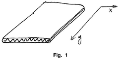
- Fig. 1 presents a general shape of a flat tube which is an object of the invention.
- the invention specifically regards tube nose, which is depicted in detail in the following figures.
- the tube is defined by reference to general directions: longitudinal and lateral. These are presented in Fig. 1 , as y axis and x axis, respectively.
- the reinforced tube nose can be located on the front area of the heat exchanger (e.g. condenser), e.g. facing the road.
- the heat exchanger e.g. condenser
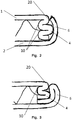
- Fig. 2 shows a first example of the flat tube.
- the tube comprises a first wall 1 and a second wall 2, which are flat and parallel to each other. Together they delimit the inner space of the tube.
- the tube has two opened ends, which define a longitudinal direction of the tube and a general path for the fluid flow.
- the tube can further comprise an inner fin.
- the fin is however optional.
- One of the lateral sides of the first wall 1 forms a multilayer nose 4 by means of consecutive folds compounded towards the second wall 2.
- the lateral side 6 of the second wall 2 is bent to cover said multilayer nose 4.
- the folds are at least partially displaced laterally towards the inner side of the tube with respect to the first bending point 20 of said lateral side of the first wall 1.
- the multilayer nose is constituted by flat portions of first and second walls 1, 2 and multiple layers of the multilayer nose 4.
- the inner facing arched portions 10 of the folds laterally precede the first bending point 20 of the multilayer nose 4.
- the folds of the multilayer nose 4 are substantially parallel to the first and second walls.
- planes of the folds are parallel to planes of the first wall 1 and the second wall 2.
- the respective end of the second wall 2 is bent around the multilayer nose 4 so that it encompasses it.
- this end consists of a single layer.
- the lateral end of the second wall 2 forms a side wall 6, which covers the multilayer nose 4 of the first wall 1. This further strengthens the tube. At the same time it protects the multilayer nose 4 and enables the tube to have a unitary, unobtrusive shape.
- Fig. 3 shows the second example of the tube.
- the side wall 6 is also double walled. This fold extends along the circumference of the multilayer nose 4.
- the examples present folds of certain lateral length.
- the lateral length of folds of the multilayer nose 4 is dependent on the lateral length of the walls of the multilayer nose 4. The longer the folds, the more resistant the nose of the tube, as the thicknesses of the multilayer nose 4 and the side of the second wall 6 compound at longer distance.
- the tube according to the invention may be a tube made of a single sheet of material. It can also be made of two sheets of material, constituting for example separately its first and second walls. Consequently, the disclosed nose of the tube can be present on one lateral side of the tube, or both lateral sides of the tube.
- the thickness of the reinforced tube nose can be in the range [0.5 x tube height ; 1.5 x tube height] and preferentially in the range [0.5 x tube height; tube height].
- the tube height here is defined along an axis perpendicular to longitudinal and lateral directions.
- These tubes can be produced by roll forming, similar to the process for currently known tubes with bends or folds.
Landscapes
- Engineering & Computer Science (AREA)
- Physics & Mathematics (AREA)
- Thermal Sciences (AREA)
- Mechanical Engineering (AREA)
- General Engineering & Computer Science (AREA)
- Geometry (AREA)
- Heat-Exchange Devices With Radiators And Conduit Assemblies (AREA)
Abstract
Description
- The object of the invention is a flat tube for a heat exchanger and a heat exchanger.
- There are known in the art tubes for heat exchangers, for example condensers, which are used to guide a fluid and enable its cooling.
- Such heat exchangers can be implemented in vehicles, e.g. cars. These vehicles are directly exposed to debris such as stones or other objects, either when they are moving or when they are stationary. The stones can travel at significant speed and can impact the heat exchanger, which in most cases is situated in front of the car and is at least partly exposed or can be reached after passing through the radiator grill. Impact of such objects can cause damage to the elements of the heat exchanger, which may lead to leaks of the fluid flowing through them and/or to deterioration of their performance.
- It is thus desirable to provide an improved tube for a heat exchanger, which would be more resistant to debris and consequently which would reduce a chance of leakage and/or decrease in performance.
- The object of invention is a flat tube for a heat exchanger, with two open ends defining its longitudinal direction, comprising a first wall and a second wall which are flat and parallel to each other, thereby delimiting the inner space of the tube, wherein one of the lateral sides of the first wall forms a multilayer nose by means of consecutive folds compounded towards the second wall, the lateral side of the second wall being bent to cover said multilayer nose, wherein the folds are at least partially displaced laterally towards the inner side of the tube with respect to the first bending point of said lateral side of the first wall.
- Preferably, the inner facing arched portions of the folds laterally precede the first bending point of the multilayer nose.
- Preferably, the lateral side of the second wall, bent over the multilayer nose, is also double walled.
- Preferably, the lateral side of the second wall, bent over the multilayer nose, consists of one layer.
- Preferably, the thickness of the reinforced tube nose in lateral direction is in the range [0.5 x tube height ; 1.5 x tube height] and preferentially in the range [0.5 x tube height; tube height].
- Another object of the invention is a heat exchanger comprising a described tube.
- The object of the invention has been presented by means of a drawing, in which:
-
Fig. 1 shows a general shape of a flat tube, -
Fig. 2 presents a tube according to a first example, -
Fig. 3 presents a tube according to a second example. -
Fig. 1 presents a general shape of a flat tube which is an object of the invention. The invention specifically regards tube nose, which is depicted in detail in the following figures. The tube is defined by reference to general directions: longitudinal and lateral. These are presented inFig. 1 , as y axis and x axis, respectively. The reinforced tube nose can be located on the front area of the heat exchanger (e.g. condenser), e.g. facing the road. -
Fig. 2 shows a first example of the flat tube. The tube comprises afirst wall 1 and asecond wall 2, which are flat and parallel to each other. Together they delimit the inner space of the tube. The tube has two opened ends, which define a longitudinal direction of the tube and a general path for the fluid flow. The tube can further comprise an inner fin. The fin is however optional. One of the lateral sides of thefirst wall 1 forms amultilayer nose 4 by means of consecutive folds compounded towards thesecond wall 2. Thelateral side 6 of thesecond wall 2 is bent to cover saidmultilayer nose 4. The folds are at least partially displaced laterally towards the inner side of the tube with respect to thefirst bending point 20 of said lateral side of thefirst wall 1. This means that there is at least one cross-section of the tube in which the multilayer nose is constituted by flat portions of first andsecond walls multilayer nose 4. Preferably, the inner facingarched portions 10 of the folds laterally precede thefirst bending point 20 of themultilayer nose 4. - Preferably, the folds of the
multilayer nose 4 are substantially parallel to the first and second walls. In other words, planes of the folds are parallel to planes of thefirst wall 1 and thesecond wall 2. - The respective end of the
second wall 2 is bent around themultilayer nose 4 so that it encompasses it. In this example, this end consists of a single layer. In other words, the lateral end of thesecond wall 2 forms aside wall 6, which covers themultilayer nose 4 of thefirst wall 1. This further strengthens the tube. At the same time it protects themultilayer nose 4 and enables the tube to have a unitary, unobtrusive shape. -
Fig. 3 shows the second example of the tube. In this example, theside wall 6 is also double walled. This fold extends along the circumference of themultilayer nose 4. - The examples present folds of certain lateral length. The lateral length of folds of the
multilayer nose 4 is dependent on the lateral length of the walls of themultilayer nose 4. The longer the folds, the more resistant the nose of the tube, as the thicknesses of themultilayer nose 4 and the side of thesecond wall 6 compound at longer distance. - The tube according to the invention may be a tube made of a single sheet of material. It can also be made of two sheets of material, constituting for example separately its first and second walls. Consequently, the disclosed nose of the tube can be present on one lateral side of the tube, or both lateral sides of the tube. The thickness of the reinforced tube nose can be in the range [0.5 x tube height ; 1.5 x tube height] and preferentially in the range [0.5 x tube height; tube height]. The tube height here is defined along an axis perpendicular to longitudinal and lateral directions.
- These tubes can be produced by roll forming, similar to the process for currently known tubes with bends or folds.
Claims (6)
- A flat tube for a heat exchanger, with two open ends defining its longitudinal direction, comprising a first wall (1) and a second wall (2) which are flat and parallel to each other, thereby delimiting the inner space of the tube, wherein one of the lateral sides of the first wall (1) forms a multilayer nose (4) by means of consecutive folds compounded towards the second wall (2), the lateral side (6) of the second wall (2) being bent to cover said multilayer nose (4), wherein the folds are at least partially displaced laterally towards the inner side of the tube with respect to the first bending point (20) of said lateral side of the first wall (1).
- The tube according to claim 1, wherein the inner facing arched portions (10) of the folds laterally precede the first bending point (20) of the multilayer nose (4).
- The tube according to any preceding claim, wherein the lateral side of the second wall (2), bent over the multilayer nose (4), is also double walled.
- The tube according to any of claims 1-2, wherein the lateral side of the second wall (2), bent over the multilayer nose (4), consists of one layer.
- The tube according to any preceding claim, wherein the thickness of the reinforced tube nose in lateral direction is in the range [0.5 x tube height ; 1.5 x tube height] and preferentially in the range [0.5 x tube height; tube height].
- A heat exchanger comprising a tube according to any of claims 1-5.
Priority Applications (1)
| Application Number | Priority Date | Filing Date | Title |
|---|---|---|---|
| EP17169136.3A EP3399266B1 (en) | 2017-05-02 | 2017-05-02 | A flat tube for a heat exchanger and a heat exchanger |
Applications Claiming Priority (1)
| Application Number | Priority Date | Filing Date | Title |
|---|---|---|---|
| EP17169136.3A EP3399266B1 (en) | 2017-05-02 | 2017-05-02 | A flat tube for a heat exchanger and a heat exchanger |
Publications (2)
| Publication Number | Publication Date |
|---|---|
| EP3399266A1 true EP3399266A1 (en) | 2018-11-07 |
| EP3399266B1 EP3399266B1 (en) | 2023-05-31 |
Family
ID=58668771
Family Applications (1)
| Application Number | Title | Priority Date | Filing Date |
|---|---|---|---|
| EP17169136.3A Active EP3399266B1 (en) | 2017-05-02 | 2017-05-02 | A flat tube for a heat exchanger and a heat exchanger |
Country Status (1)
| Country | Link |
|---|---|
| EP (1) | EP3399266B1 (en) |
Citations (6)
| Publication number | Priority date | Publication date | Assignee | Title |
|---|---|---|---|---|
| WO1998044306A1 (en) * | 1997-03-28 | 1998-10-08 | Sanden Corporation | Heat exchanger tube and method of its manufacture |
| DE19753724A1 (en) * | 1997-12-04 | 1999-06-10 | Behr Gmbh & Co | Heat transfer device e.g. for cooling engine oil in vehicles |
| WO2007084984A2 (en) * | 2006-01-19 | 2007-07-26 | Modine Manufacturing Company | Flat tube, flat tube heat exchanger, and method of manufacturing same |
| DE102006016711A1 (en) * | 2006-04-08 | 2007-10-11 | Modine Manufacturing Co., Racine | Heat exchanger tube comprises first thin sheet of material partially forming broad and narrow sides of tube body and partially enclosing an interior space, and second sheet of material partially forming fin brazed to tube body |
| US20090019695A1 (en) * | 2006-01-19 | 2009-01-22 | Werner Zobel | Flat tube, flat tube heat exchanger, and method of manufacturing same |
| EP3096102A1 (en) * | 2015-05-22 | 2016-11-23 | Delphi Automotive Systems Luxembourg SA | Flat tube for a heat exchanger |
-
2017
- 2017-05-02 EP EP17169136.3A patent/EP3399266B1/en active Active
Patent Citations (6)
| Publication number | Priority date | Publication date | Assignee | Title |
|---|---|---|---|---|
| WO1998044306A1 (en) * | 1997-03-28 | 1998-10-08 | Sanden Corporation | Heat exchanger tube and method of its manufacture |
| DE19753724A1 (en) * | 1997-12-04 | 1999-06-10 | Behr Gmbh & Co | Heat transfer device e.g. for cooling engine oil in vehicles |
| WO2007084984A2 (en) * | 2006-01-19 | 2007-07-26 | Modine Manufacturing Company | Flat tube, flat tube heat exchanger, and method of manufacturing same |
| US20090019695A1 (en) * | 2006-01-19 | 2009-01-22 | Werner Zobel | Flat tube, flat tube heat exchanger, and method of manufacturing same |
| DE102006016711A1 (en) * | 2006-04-08 | 2007-10-11 | Modine Manufacturing Co., Racine | Heat exchanger tube comprises first thin sheet of material partially forming broad and narrow sides of tube body and partially enclosing an interior space, and second sheet of material partially forming fin brazed to tube body |
| EP3096102A1 (en) * | 2015-05-22 | 2016-11-23 | Delphi Automotive Systems Luxembourg SA | Flat tube for a heat exchanger |
Also Published As
| Publication number | Publication date |
|---|---|
| EP3399266B1 (en) | 2023-05-31 |
Similar Documents
| Publication | Publication Date | Title |
|---|---|---|
| JP6069194B2 (en) | Method of forming a heat exchanger tube | |
| US20110005738A1 (en) | Soldered flat tube for condensers and/or evaporators | |
| WO2018059443A1 (en) | Heat exchange assembly for heat exchanger, heat exchanger, and mold | |
| US8522862B2 (en) | Vehicle radiator | |
| US11226161B2 (en) | Heat exchanger | |
| US20200080794A1 (en) | B-tube reform for improved thermal cycle performance | |
| EP3096102A1 (en) | Flat tube for a heat exchanger | |
| JP5970924B2 (en) | Heat exchanger with tubes | |
| EP3623738B1 (en) | Heat exchanger tube | |
| JP6050958B2 (en) | Flat heat exchanger tube | |
| EP3399266B1 (en) | A flat tube for a heat exchanger and a heat exchanger | |
| EP3399267A1 (en) | A flat tube for a heat exchanger and a heat exchanger | |
| EP3399265B1 (en) | A flat tube for a heat exchanger and a heat exchanger | |
| US11421944B2 (en) | Flat tube for a heat exchanger and a heat exchanger that is more resistant to debris | |
| JP2009109183A (en) | Tube for heat exchanger | |
| CN110017703B (en) | heat exchanger | |
| EP3521746B1 (en) | A flat tube for a heat exchanger | |
| US12209815B2 (en) | Flat heat exchanger tube | |
| US20150198374A1 (en) | Heat exchanger | |
| EP3040669B1 (en) | Turbulator fin for a tube-fin assembly adapted for a heat exchanger and a fin forming roll adapted to form said turbulator fin | |
| EP3521745B1 (en) | A flat tube assembly for a heat exchanger | |
| US20140262182A1 (en) | Micro channel heat exchanger alloy system | |
| JP2003056945A (en) | Condenser of air conditioner for automobile | |
| JP2887495B2 (en) | Evaporator for car air conditioner | |
| JP6787301B2 (en) | Heat exchanger tube and heat exchanger |
Legal Events
| Date | Code | Title | Description |
|---|---|---|---|
| PUAI | Public reference made under article 153(3) epc to a published international application that has entered the european phase |
Free format text: ORIGINAL CODE: 0009012 |
|
| STAA | Information on the status of an ep patent application or granted ep patent |
Free format text: STATUS: THE APPLICATION HAS BEEN PUBLISHED |
|
| AK | Designated contracting states |
Kind code of ref document: A1 Designated state(s): AL AT BE BG CH CY CZ DE DK EE ES FI FR GB GR HR HU IE IS IT LI LT LU LV MC MK MT NL NO PL PT RO RS SE SI SK SM TR |
|
| AX | Request for extension of the european patent |
Extension state: BA ME |
|
| STAA | Information on the status of an ep patent application or granted ep patent |
Free format text: STATUS: REQUEST FOR EXAMINATION WAS MADE |
|
| 17P | Request for examination filed |
Effective date: 20190510 |
|
| RBV | Designated contracting states (corrected) |
Designated state(s): AL AT BE BG CH CY CZ DE DK EE ES FI FR GB GR HR HU IE IS IT LI LT LU LV MC MK MT NL NO PL PT RO RS SE SI SK SM TR |
|
| STAA | Information on the status of an ep patent application or granted ep patent |
Free format text: STATUS: EXAMINATION IS IN PROGRESS |
|
| 17Q | First examination report despatched |
Effective date: 20210609 |
|
| GRAP | Despatch of communication of intention to grant a patent |
Free format text: ORIGINAL CODE: EPIDOSNIGR1 |
|
| STAA | Information on the status of an ep patent application or granted ep patent |
Free format text: STATUS: GRANT OF PATENT IS INTENDED |
|
| INTG | Intention to grant announced |
Effective date: 20221207 |
|
| GRAS | Grant fee paid |
Free format text: ORIGINAL CODE: EPIDOSNIGR3 |
|
| GRAA | (expected) grant |
Free format text: ORIGINAL CODE: 0009210 |
|
| STAA | Information on the status of an ep patent application or granted ep patent |
Free format text: STATUS: THE PATENT HAS BEEN GRANTED |
|
| AK | Designated contracting states |
Kind code of ref document: B1 Designated state(s): AL AT BE BG CH CY CZ DE DK EE ES FI FR GB GR HR HU IE IS IT LI LT LU LV MC MK MT NL NO PL PT RO RS SE SI SK SM TR |
|
| REG | Reference to a national code |
Ref country code: GB Ref legal event code: FG4D Ref country code: CH Ref legal event code: EP |
|
| REG | Reference to a national code |
Ref country code: DE Ref legal event code: R096 Ref document number: 602017069163 Country of ref document: DE |
|
| RIN2 | Information on inventor provided after grant (corrected) |
Inventor name: DURBECQ, GAEL |
|
| REG | Reference to a national code |
Ref country code: AT Ref legal event code: REF Ref document number: 1571144 Country of ref document: AT Kind code of ref document: T Effective date: 20230615 |
|
| REG | Reference to a national code |
Ref country code: IE Ref legal event code: FG4D |
|
| P01 | Opt-out of the competence of the unified patent court (upc) registered |
Effective date: 20230528 |
|
| REG | Reference to a national code |
Ref country code: LT Ref legal event code: MG9D |
|
| REG | Reference to a national code |
Ref country code: NL Ref legal event code: MP Effective date: 20230531 |
|
| REG | Reference to a national code |
Ref country code: AT Ref legal event code: MK05 Ref document number: 1571144 Country of ref document: AT Kind code of ref document: T Effective date: 20230531 |
|
| PG25 | Lapsed in a contracting state [announced via postgrant information from national office to epo] |
Ref country code: SE Free format text: LAPSE BECAUSE OF FAILURE TO SUBMIT A TRANSLATION OF THE DESCRIPTION OR TO PAY THE FEE WITHIN THE PRESCRIBED TIME-LIMIT Effective date: 20230531 Ref country code: NO Free format text: LAPSE BECAUSE OF FAILURE TO SUBMIT A TRANSLATION OF THE DESCRIPTION OR TO PAY THE FEE WITHIN THE PRESCRIBED TIME-LIMIT Effective date: 20230831 Ref country code: ES Free format text: LAPSE BECAUSE OF FAILURE TO SUBMIT A TRANSLATION OF THE DESCRIPTION OR TO PAY THE FEE WITHIN THE PRESCRIBED TIME-LIMIT Effective date: 20230531 Ref country code: AT Free format text: LAPSE BECAUSE OF FAILURE TO SUBMIT A TRANSLATION OF THE DESCRIPTION OR TO PAY THE FEE WITHIN THE PRESCRIBED TIME-LIMIT Effective date: 20230531 |
|
| PG25 | Lapsed in a contracting state [announced via postgrant information from national office to epo] |
Ref country code: RS Free format text: LAPSE BECAUSE OF FAILURE TO SUBMIT A TRANSLATION OF THE DESCRIPTION OR TO PAY THE FEE WITHIN THE PRESCRIBED TIME-LIMIT Effective date: 20230531 Ref country code: PL Free format text: LAPSE BECAUSE OF FAILURE TO SUBMIT A TRANSLATION OF THE DESCRIPTION OR TO PAY THE FEE WITHIN THE PRESCRIBED TIME-LIMIT Effective date: 20230531 Ref country code: NL Free format text: LAPSE BECAUSE OF FAILURE TO SUBMIT A TRANSLATION OF THE DESCRIPTION OR TO PAY THE FEE WITHIN THE PRESCRIBED TIME-LIMIT Effective date: 20230531 Ref country code: LV Free format text: LAPSE BECAUSE OF FAILURE TO SUBMIT A TRANSLATION OF THE DESCRIPTION OR TO PAY THE FEE WITHIN THE PRESCRIBED TIME-LIMIT Effective date: 20230531 Ref country code: LT Free format text: LAPSE BECAUSE OF FAILURE TO SUBMIT A TRANSLATION OF THE DESCRIPTION OR TO PAY THE FEE WITHIN THE PRESCRIBED TIME-LIMIT Effective date: 20230531 Ref country code: IS Free format text: LAPSE BECAUSE OF FAILURE TO SUBMIT A TRANSLATION OF THE DESCRIPTION OR TO PAY THE FEE WITHIN THE PRESCRIBED TIME-LIMIT Effective date: 20230930 Ref country code: HR Free format text: LAPSE BECAUSE OF FAILURE TO SUBMIT A TRANSLATION OF THE DESCRIPTION OR TO PAY THE FEE WITHIN THE PRESCRIBED TIME-LIMIT Effective date: 20230531 |
|
| PG25 | Lapsed in a contracting state [announced via postgrant information from national office to epo] |
Ref country code: FI Free format text: LAPSE BECAUSE OF FAILURE TO SUBMIT A TRANSLATION OF THE DESCRIPTION OR TO PAY THE FEE WITHIN THE PRESCRIBED TIME-LIMIT Effective date: 20230531 |
|
| PG25 | Lapsed in a contracting state [announced via postgrant information from national office to epo] |
Ref country code: SK Free format text: LAPSE BECAUSE OF FAILURE TO SUBMIT A TRANSLATION OF THE DESCRIPTION OR TO PAY THE FEE WITHIN THE PRESCRIBED TIME-LIMIT Effective date: 20230531 |
|
| PG25 | Lapsed in a contracting state [announced via postgrant information from national office to epo] |
Ref country code: SM Free format text: LAPSE BECAUSE OF FAILURE TO SUBMIT A TRANSLATION OF THE DESCRIPTION OR TO PAY THE FEE WITHIN THE PRESCRIBED TIME-LIMIT Effective date: 20230531 Ref country code: SK Free format text: LAPSE BECAUSE OF FAILURE TO SUBMIT A TRANSLATION OF THE DESCRIPTION OR TO PAY THE FEE WITHIN THE PRESCRIBED TIME-LIMIT Effective date: 20230531 Ref country code: RO Free format text: LAPSE BECAUSE OF FAILURE TO SUBMIT A TRANSLATION OF THE DESCRIPTION OR TO PAY THE FEE WITHIN THE PRESCRIBED TIME-LIMIT Effective date: 20230531 Ref country code: PT Free format text: LAPSE BECAUSE OF FAILURE TO SUBMIT A TRANSLATION OF THE DESCRIPTION OR TO PAY THE FEE WITHIN THE PRESCRIBED TIME-LIMIT Effective date: 20231002 Ref country code: EE Free format text: LAPSE BECAUSE OF FAILURE TO SUBMIT A TRANSLATION OF THE DESCRIPTION OR TO PAY THE FEE WITHIN THE PRESCRIBED TIME-LIMIT Effective date: 20230531 Ref country code: DK Free format text: LAPSE BECAUSE OF FAILURE TO SUBMIT A TRANSLATION OF THE DESCRIPTION OR TO PAY THE FEE WITHIN THE PRESCRIBED TIME-LIMIT Effective date: 20230531 Ref country code: CZ Free format text: LAPSE BECAUSE OF FAILURE TO SUBMIT A TRANSLATION OF THE DESCRIPTION OR TO PAY THE FEE WITHIN THE PRESCRIBED TIME-LIMIT Effective date: 20230531 |
|
| REG | Reference to a national code |
Ref country code: DE Ref legal event code: R097 Ref document number: 602017069163 Country of ref document: DE |
|
| PLBE | No opposition filed within time limit |
Free format text: ORIGINAL CODE: 0009261 |
|
| STAA | Information on the status of an ep patent application or granted ep patent |
Free format text: STATUS: NO OPPOSITION FILED WITHIN TIME LIMIT |
|
| PG25 | Lapsed in a contracting state [announced via postgrant information from national office to epo] |
Ref country code: SI Free format text: LAPSE BECAUSE OF FAILURE TO SUBMIT A TRANSLATION OF THE DESCRIPTION OR TO PAY THE FEE WITHIN THE PRESCRIBED TIME-LIMIT Effective date: 20230531 |
|
| 26N | No opposition filed |
Effective date: 20240301 |
|
| PG25 | Lapsed in a contracting state [announced via postgrant information from national office to epo] |
Ref country code: SI Free format text: LAPSE BECAUSE OF FAILURE TO SUBMIT A TRANSLATION OF THE DESCRIPTION OR TO PAY THE FEE WITHIN THE PRESCRIBED TIME-LIMIT Effective date: 20230531 Ref country code: IT Free format text: LAPSE BECAUSE OF FAILURE TO SUBMIT A TRANSLATION OF THE DESCRIPTION OR TO PAY THE FEE WITHIN THE PRESCRIBED TIME-LIMIT Effective date: 20230531 |
|
| PG25 | Lapsed in a contracting state [announced via postgrant information from national office to epo] |
Ref country code: BG Free format text: LAPSE BECAUSE OF FAILURE TO SUBMIT A TRANSLATION OF THE DESCRIPTION OR TO PAY THE FEE WITHIN THE PRESCRIBED TIME-LIMIT Effective date: 20230531 |
|
| PG25 | Lapsed in a contracting state [announced via postgrant information from national office to epo] |
Ref country code: BG Free format text: LAPSE BECAUSE OF FAILURE TO SUBMIT A TRANSLATION OF THE DESCRIPTION OR TO PAY THE FEE WITHIN THE PRESCRIBED TIME-LIMIT Effective date: 20230531 |
|
| REG | Reference to a national code |
Ref country code: CH Ref legal event code: PL |
|
| PG25 | Lapsed in a contracting state [announced via postgrant information from national office to epo] |
Ref country code: MC Free format text: LAPSE BECAUSE OF FAILURE TO SUBMIT A TRANSLATION OF THE DESCRIPTION OR TO PAY THE FEE WITHIN THE PRESCRIBED TIME-LIMIT Effective date: 20230531 |
|
| PG25 | Lapsed in a contracting state [announced via postgrant information from national office to epo] |
Ref country code: LU Free format text: LAPSE BECAUSE OF NON-PAYMENT OF DUE FEES Effective date: 20240502 |
|
| GBPC | Gb: european patent ceased through non-payment of renewal fee |
Effective date: 20240502 |
|
| PG25 | Lapsed in a contracting state [announced via postgrant information from national office to epo] |
Ref country code: MC Free format text: LAPSE BECAUSE OF FAILURE TO SUBMIT A TRANSLATION OF THE DESCRIPTION OR TO PAY THE FEE WITHIN THE PRESCRIBED TIME-LIMIT Effective date: 20230531 Ref country code: LU Free format text: LAPSE BECAUSE OF NON-PAYMENT OF DUE FEES Effective date: 20240502 Ref country code: CH Free format text: LAPSE BECAUSE OF NON-PAYMENT OF DUE FEES Effective date: 20240531 |
|
| REG | Reference to a national code |
Ref country code: BE Ref legal event code: MM Effective date: 20240531 |
|
| PG25 | Lapsed in a contracting state [announced via postgrant information from national office to epo] |
Ref country code: IE Free format text: LAPSE BECAUSE OF NON-PAYMENT OF DUE FEES Effective date: 20240502 |
|
| PG25 | Lapsed in a contracting state [announced via postgrant information from national office to epo] |
Ref country code: BE Free format text: LAPSE BECAUSE OF NON-PAYMENT OF DUE FEES Effective date: 20240531 |
|
| PG25 | Lapsed in a contracting state [announced via postgrant information from national office to epo] |
Ref country code: GB Free format text: LAPSE BECAUSE OF NON-PAYMENT OF DUE FEES Effective date: 20240502 |
|
| PGFP | Annual fee paid to national office [announced via postgrant information from national office to epo] |
Ref country code: DE Payment date: 20250513 Year of fee payment: 9 |
|
| PGFP | Annual fee paid to national office [announced via postgrant information from national office to epo] |
Ref country code: FR Payment date: 20250530 Year of fee payment: 9 |
|
| PG25 | Lapsed in a contracting state [announced via postgrant information from national office to epo] |
Ref country code: CY Free format text: LAPSE BECAUSE OF FAILURE TO SUBMIT A TRANSLATION OF THE DESCRIPTION OR TO PAY THE FEE WITHIN THE PRESCRIBED TIME-LIMIT; INVALID AB INITIO Effective date: 20170502 |
|
| PG25 | Lapsed in a contracting state [announced via postgrant information from national office to epo] |
Ref country code: HU Free format text: LAPSE BECAUSE OF FAILURE TO SUBMIT A TRANSLATION OF THE DESCRIPTION OR TO PAY THE FEE WITHIN THE PRESCRIBED TIME-LIMIT; INVALID AB INITIO Effective date: 20170502 |
|
| PG25 | Lapsed in a contracting state [announced via postgrant information from national office to epo] |
Ref country code: GR Free format text: LAPSE BECAUSE OF FAILURE TO SUBMIT A TRANSLATION OF THE DESCRIPTION OR TO PAY THE FEE WITHIN THE PRESCRIBED TIME-LIMIT; INVALID AB INITIO Effective date: 20170502 |