EP3399254A1 - Compressor oil storage assembly, air conditioner, and control method therefor - Google Patents
Compressor oil storage assembly, air conditioner, and control method therefor Download PDFInfo
- Publication number
- EP3399254A1 EP3399254A1 EP17805864.0A EP17805864A EP3399254A1 EP 3399254 A1 EP3399254 A1 EP 3399254A1 EP 17805864 A EP17805864 A EP 17805864A EP 3399254 A1 EP3399254 A1 EP 3399254A1
- Authority
- EP
- European Patent Office
- Prior art keywords
- oil
- compressor
- electromagnetic valve
- turn
- storage tank
- Prior art date
- Legal status (The legal status is an assumption and is not a legal conclusion. Google has not performed a legal analysis and makes no representation as to the accuracy of the status listed.)
- Granted
Links
Images
Classifications
-
- F—MECHANICAL ENGINEERING; LIGHTING; HEATING; WEAPONS; BLASTING
- F25—REFRIGERATION OR COOLING; COMBINED HEATING AND REFRIGERATION SYSTEMS; HEAT PUMP SYSTEMS; MANUFACTURE OR STORAGE OF ICE; LIQUEFACTION SOLIDIFICATION OF GASES
- F25B—REFRIGERATION MACHINES, PLANTS OR SYSTEMS; COMBINED HEATING AND REFRIGERATION SYSTEMS; HEAT PUMP SYSTEMS
- F25B31/00—Compressor arrangements
- F25B31/002—Lubrication
- F25B31/004—Lubrication oil recirculating arrangements
-
- F—MECHANICAL ENGINEERING; LIGHTING; HEATING; WEAPONS; BLASTING
- F25—REFRIGERATION OR COOLING; COMBINED HEATING AND REFRIGERATION SYSTEMS; HEAT PUMP SYSTEMS; MANUFACTURE OR STORAGE OF ICE; LIQUEFACTION SOLIDIFICATION OF GASES
- F25B—REFRIGERATION MACHINES, PLANTS OR SYSTEMS; COMBINED HEATING AND REFRIGERATION SYSTEMS; HEAT PUMP SYSTEMS
- F25B43/00—Arrangements for separating or purifying gases or liquids; Arrangements for vaporising the residuum of liquid refrigerant, e.g. by heat
- F25B43/006—Accumulators
-
- F—MECHANICAL ENGINEERING; LIGHTING; HEATING; WEAPONS; BLASTING
- F25—REFRIGERATION OR COOLING; COMBINED HEATING AND REFRIGERATION SYSTEMS; HEAT PUMP SYSTEMS; MANUFACTURE OR STORAGE OF ICE; LIQUEFACTION SOLIDIFICATION OF GASES
- F25B—REFRIGERATION MACHINES, PLANTS OR SYSTEMS; COMBINED HEATING AND REFRIGERATION SYSTEMS; HEAT PUMP SYSTEMS
- F25B49/00—Arrangement or mounting of control or safety devices
- F25B49/02—Arrangement or mounting of control or safety devices for compression type machines, plants or systems
- F25B49/022—Compressor control arrangements
-
- F—MECHANICAL ENGINEERING; LIGHTING; HEATING; WEAPONS; BLASTING
- F25—REFRIGERATION OR COOLING; COMBINED HEATING AND REFRIGERATION SYSTEMS; HEAT PUMP SYSTEMS; MANUFACTURE OR STORAGE OF ICE; LIQUEFACTION SOLIDIFICATION OF GASES
- F25B—REFRIGERATION MACHINES, PLANTS OR SYSTEMS; COMBINED HEATING AND REFRIGERATION SYSTEMS; HEAT PUMP SYSTEMS
- F25B2600/00—Control issues
- F25B2600/02—Compressor control
-
- F—MECHANICAL ENGINEERING; LIGHTING; HEATING; WEAPONS; BLASTING
- F25—REFRIGERATION OR COOLING; COMBINED HEATING AND REFRIGERATION SYSTEMS; HEAT PUMP SYSTEMS; MANUFACTURE OR STORAGE OF ICE; LIQUEFACTION SOLIDIFICATION OF GASES
- F25B—REFRIGERATION MACHINES, PLANTS OR SYSTEMS; COMBINED HEATING AND REFRIGERATION SYSTEMS; HEAT PUMP SYSTEMS
- F25B2600/00—Control issues
- F25B2600/25—Control of valves
-
- F—MECHANICAL ENGINEERING; LIGHTING; HEATING; WEAPONS; BLASTING
- F25—REFRIGERATION OR COOLING; COMBINED HEATING AND REFRIGERATION SYSTEMS; HEAT PUMP SYSTEMS; MANUFACTURE OR STORAGE OF ICE; LIQUEFACTION SOLIDIFICATION OF GASES
- F25B—REFRIGERATION MACHINES, PLANTS OR SYSTEMS; COMBINED HEATING AND REFRIGERATION SYSTEMS; HEAT PUMP SYSTEMS
- F25B2600/00—Control issues
- F25B2600/25—Control of valves
- F25B2600/2519—On-off valves
Definitions
- the present disclosure relates to a field of air conditioner technology, and more particularly to an oil storage assembly for a compressor, an air conditioner and a control method thereof.
- a main objective of the present disclosure is to provide an oil storage assembly for a compressor, an air conditioner and a control method thereof, which may aim to solve a technical problem that the compressor is easy to be short of oil after long-term shutdown.
- the oil storage assembly for the compressor provided by the present disclosure includes a compressor and an oil storage tank.
- the compressor is provided with an oil drain outlet.
- the oil storage tank is provided with an oil inlet and an oil outlet.
- the oil drain outlet and the oil inlet are connected with a first pipeline, and the first pipeline is provided with a first electromagnetic valve.
- a second pipeline is connected between the oil outlet and a return air port of the compressor, and the second pipeline is provided with a second electromagnetic valve.
- a height of the oil drain outlet relative to a bottom of the compressor is less than half a height of the compressor.
- the oil drain outlet is higher than a top of a cylinder inside the compressor.
- a diameter of the first pipeline is less than or equal to a diameter of an air outlet of the compressor.
- the oil storage assembly for the compressor is applied to an air conditioner, both the first electromagnetic valve and the second electromagnetic valve are connected with a controller of the air conditioner, wherein the controller is configured to control the second electromagnetic valve to turn off and control the first electromagnetic valve to turn on when receiving a stop signal, to enable the oil storage tank to store oil when the compressor is shut down; the controller is configured to control the first electromagnetic valve to turn off when the oil storage tank finishes storing oil during shutdown of the compressor; the controller is configured to control the second electromagnetic valve to turn on to enable the oil storage tank to drain oil when receiving a power-on signal.
- the controller is further configured to control the first electromagnetic valve to turn off and control the second electromagnetic valve to turn on for a first preset time period, which enables the oil storage tank to switch to a negative pressure state.
- the controller is further configured to turn off the second electromagnetic valve when the oil storage tank finishes draining oil.
- the controller when the compressor is operating, is further configured to calculate a discharge superheat degree of the compressor, and to control the second electromagnetic valve to turn off and control the first electromagnetic valve to turn on when the discharge superheat degree continues to be greater than a preset threshold for a second preset time period, to enable the oil storage tank to store oil during operating process of the compressor.
- the controller is further configured to turn off the first electromagnetic valve.
- an air conditioner further provided by the present disclosure includes an oil storage assembly for a compressor.
- the oil storage assembly of the compressor includes a compressor and an oil storage tank.
- the compressor is provided with an oil drain outlet.
- the oil storage tank is provided with an oil inlet and an oil outlet.
- the oil drain outlet and the oil inlet are connected with a first pipeline, and the first pipeline is provided with a first electromagnetic valve.
- a second pipeline is connected between the oil outlet and a return air port of the compressor, and the second pipeline is provided with a second electromagnetic valve.
- a control method of an air conditioner further provided by the present disclosure includes:
- control method before controlling the second electromagnetic valve to turn off and controlling the first electromagnetic valve to turn on, the control method further includes: controlling the first electromagnetic valve to turn off and controlling the second electromagnetic valve to turn on for a first preset time period, to enable the oil storage tank to switch to a negative pressure state.
- control method further includes: turning off the second electromagnetic valve when the oil storage tank finishes draining oil.
- control method further includes:
- control method before controlling the second electromagnetic valve to turn off and controlling the first electromagnetic valve to turn on to enable the oil storage tank to store oil when the compressor is operating, the control method further includes: controlling the first electromagnetic valve to turn off and controlling the second electromagnetic valve to turn on for a third preset time period, to enable the oil storage tank to switch to a negative pressure state.
- the present disclosure further provides a non-transitory computer-readable storage medium.
- the storage medium is stored with computer programs, in which the programs are configured to be executed by a processor to realize the control method above.
- the oil storage assembly for the compressor, the air conditioner and the control method thereof provided by the present disclosure control the second electromagnetic valve to turn off and control the first electromagnetic valve to turn on when receiving the stop signal , to enable the refrigeration oil in the compressor to flow into the oil storage tank via the first pipeline, which controls the oil storage tank to store oil when the compressor is shut down; and control the first electromagnetic valve to turn off when the oil storage tank finishes storing oil during shutdown of the compressor; and control the second electromagnetic to turn on when receiving the power-on signal, to enable the refrigeration oil in the oil storage tank to flow into the compressor via the second pipeline, which controls the oil storage tank to drain oil.
- the refrigeration oil with a high concentration inside the oil storage tank may be stored in the oil storage tank in time, and when the compressor is restarted, the refrigeration oil with the high concentration inside the oil storage tank may be provided to the compressor in time, and thus an occurrence of the oil shortage of the compressor after a long-time shutdown is effectively avoided.
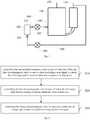
- the oil storage assembly for the compressor includes a compressor 100 and an oil storage tank 200.
- the compressor 100 is provided with an oil drain outlet 110.
- the oil storage tank 200 is provided with an oil inlet 210 and an oil outlet 220.
- the oil drain outlet 110 and the oil inlet 210 are connected with a first pipeline 300, and the first pipeline 300 is provided with a first electromagnetic valve 400.
- a second pipeline 500 is connected between the oil outlet 220 and a return air port 120 of the compressor 100, and the second pipeline 500 is provided with a second electromagnetic valve 600.
- the oil drain outlet 110 of the compressor 100, the first pipeline 300, the oil inlet 210 of the oil storage tank 200, the oil outlet 220 of the oil storage tank 200, the second pipeline 500 and the return air port 120 of the compressor 100 are sequentially connected, forming a circuit.
- both the first electromagnetic valve 400 and the second electromagnetic valve 600 are connected with a controller of the air conditioner, wherein the controller is configured to control the first electromagnetic valve 400 and the second electromagnetic valve 600 to turn on and off.
- the controller may control the second electromagnetic valve 600 to turn off and control the first electromagnetic valve 400 to turn on when receiving a stop signal, to enable the refrigeration oil in the compressor 100 to flow into the oil storage tank 200 via the first pipeline 300, so as to control the oil storage tank 200 to store oil when the compressor 100 is shut down.
- the controller may turn off the first electromagnetic valve 400.
- the controller may control the second electromagnetic valve 600 to turn on, to enable the refrigeration oil in the oil storage tank 200 to flow into the compressor 100 via the second pipeline 500, so as to enable the oil storage tank 200 to drain oil.
- the controller when the controller detects that the compressor 100 is shut down, it can be considered that the controller receives the stop signal; or when the controller receives the shutdown signal sent by a user, it can be considered that the controller receives the stop signal.
- the first electromagnetic valve 400 is controlled to turn on, the refrigeration oil in the compressor 100 can flow into the oil storage tank 200 via the pipeline 100 under the high pressure inside the compressor 100, such that the oil storage tank 200 can store oil when the compressor is shut down.
- an oil level detecting device may be arranged in the oil storage tank 200 for detecting an oil-storing volume of the oil storage tank 200, and when the oil level detecting device detects that the oil-storing volume of the oil storage tank 200 reaches a preset oil volume, it can be considered as finishing storing oil.
- the oil level detecting device may include, for example, a float provided in the oil storage tank 200 and a proximity switch provided on the top of the oil storage tank 200, and the proximity switch automatically switches on or off depending on the distance between the float and the proximity switch.
- the first electromagnetic valve 400 When the compressor 100 is restarted, the first electromagnetic valve 400 is in a turn-off state, and the second electromagnetic valve 600 is controlled to turn on. Under a negative pressure of the return air port 120 of the compressor 100, the refrigeration oil in the oil storage tank 200 may flow into the compressor 100 via the second pipeline500, such that the refrigeration oil in the oil storage tank 200 returns to the inside of the compressor 100 again, and thus the occurrence of the oil shortage of the compressor 100 after long-term shutdown is avoided.
- oil temperature of the refrigeration oil at the bottom of the compressor 100 is relatively high, and concentration of the refrigeration oil may be relatively high.
- the compressor 100 is shut down, the refrigeration oil with the relatively high concentration in the compressor 100 can flow into the oil storage tank 200 through the oil drain outlet 110 and the first pipeline 300.
- the first electromagnetic valve 400 is controlled to turn off, such that the stored refrigeration oil is sealed in the oil storage tank 200.
- the compressor 100 is shut down for a long time, the refrigeration oil at the bottom of the compressor 100 is diluted with transferred refrigerant, and the concentration of the refrigeration oil in the oil storage tank 200 is higher at this time.
- the second electromagnetic valve 600 When the compressor 100 is restarted, the second electromagnetic valve 600 is turned on, such that the refrigeration oil with the relatively high concentration in the oil storage tank 200 returns into the compressor 100 through the oil outlet 220 and the second pipeline 500, and thus the refrigeration oil with the higher concentration is provided to the compressor 100 in time, which increases the concentration of the refrigeration oil at the bottom of the compressor 100, and effectively avoids the oil shortage in the compressor 100.
- a height of the oil drain outlet 110 relative to the bottom of the compressor 100 is less than half a height of the compressor100. Since the refrigeration oil of the compressor 100 usually accumulates at the bottom of the compressor 100, the height of the oil drain outlet 110 cannot be too high, otherwise the refrigeration oil will not reach the oil drain outlet 110.
- the oil drain outlet 110 is higher than a top of the cylinder inside the compressor, such that the oil level of the refrigeration oil inside the compressor 100 is always higher than the cylinder, which ensures that the refrigeration oil always exists at the periphery of the cylinder, so that the cylinder can always work normally.
- a diameter of the first pipeline 300 is less than or equal to a diameter of the air outlet 130 of the compressor100. Therefore, it ensures that the pressure at the air outlet 130 of the compressor 100 is not too small due to the exhaust action of the first pipeline 300, ensuring a heat exchange capacity of the air conditioner.
- a volume of the oil storage tank 200 is between 10% and 20% of a volume of the refrigeration oil of the air conditioner. Therefore, it not only ensures that the compressor 100 is not short of oil during the long-term shutdown, but also can ensure that the oil storage tank 200 does not affect the heat exchange capability of the compressor 100 too much after storing oil.
- a height of the oil inlet 210 of the oil storage tank 200 relative to the bottom of the oil storage tank 200 is greater than two-thirds of the height of the oil storage tank 200. Since the refrigeration oil flowing out through the oil drain outlet 110 of the compressor 100 may contain gaseous refrigerant, the oil inlet 210 of the oil storage tank 200 may be provided at a higher position of the oil storage tank 200, which is more advantageous for the refrigeration oil inside the compressor 100 to enter into the oil storage tank 200 via the first pipeline 300.
- the oil outlet 220 is provided at the bottom of the oil storage tank 200, which is more advantageous for the refrigeration oil in the oil storage tank 200 to flow into the compressor 100.
- the present disclosure further provides an air conditioner.
- the air conditioner includes a controller and an oil storage assembly for a compressor.
- an oil storage assembly for the compressor With respect to a specific structure of the oil storage assembly for the compressor, reference can be made to the above embodiments. Since the air conditioner adopts all the technical solutions of all the above embodiments of the compressor oil storage assembly, it also has all the beneficial effects brought by the technical solutions of the above embodiments, which will not be elaborated herein.
- a control method of an air conditioner includes the following steps.
- the controller when the controller detects that the compressor 100 is shut down, it can be considered that the stop signal is received; or when the controller receives the shutdown signal sent by a user, it can be considered that the stop signal is received.
- the first electromagnetic valve 400 When the first electromagnetic valve 400 is controlled to turn on, the refrigeration oil in the compressor 100 may flow into the oil storage tank 200 via the pipeline 100 under the high pressure inside the compressor 100, such that the oil storage tank 200 can store oil when the compressor is shut down.
- an oil level detecting device may be arranged in the oil storage tank 200 for detecting an oil-storing volume of the oil storage tank 200, and when the oil level detecting device detects that the oil-storing volume of the oil storage tank 200 reaches a preset oil volume, it can be considered as finishing storing oil.
- the oil level detecting device may include, for example, a float provided in the oil storage tank 200 and a proximity switch provided on the top of the oil storage tank 200, and the proximity switch automatically switches on or off depending on the distance between the float and the proximity switch.
- the second electromagnetic valve 600 is controlled to turn on, such that the refrigeration oil in the oil storage tank 200 flows into the compressor 100 via the second pipeline 500, to enable the oil storage tank 200 to drain oil.
- the first electromagnetic valve 400 When the compressor 100 is restarted, the first electromagnetic valve 400 is in a turn-off state, and the second electromagnetic valve 600 is controlled to turn on. Under a negative pressure of the return air port 120 of the compressor 100, the refrigeration oil in the oil storage tank 200 may flow into the compressor 100 via the second pipeline 500, such that the refrigeration oil in the oil storage tank 200 returns to the inside of the compressor 100 again, and thus the occurrence of the oil shortage of the compressor 100 after long-term shutdown is avoided.
- the second electromagnetic valve 600 is controlled to turn off.
- the oil storage tank 200 does not always communicate with the compressor 100, and further does not affect the heat exchange capacity of the compressor 100 during the normal operating process of the compressor 100.
- the power-on signal is received, and when the second electromagnetic valve 600 is controlled to turn on for a fourth preset time period, it can be considered that the oil storage tank 200 finishes draining oil.
- oil temperature of the refrigeration oil at the bottom of the compressor 100 is relatively high, and concentration of the refrigeration oil may be relatively high.
- the compressor 100 is shut down, the refrigeration oil with the relatively high concentration inside the compressor 100 can flow into the oil storage tank 200 through the oil drain outlet 110 and the first pipeline 300.
- the first electromagnetic valve 400 is controlled to turn off, such that the stored refrigeration oil is sealed in the oil storage tank 200.
- the compressor 100 is shut down for a long time, the refrigeration oil at the bottom of the compressor 100 is diluted with transferred refrigerant, and the concentration of the refrigeration oil in the oil storage tank 200 is higher at this time.
- the second electromagnetic valve 600 When the compressor 100 is restarted, the second electromagnetic valve 600 is turned on, such that the refrigeration oil with the relatively high concentration in the oil storage tank 200 returns into the compressor 100 through the oil outlet 220 and the second pipeline 500, and thus the refrigeration oil with the higher concentration is provided to the compressor 100 in time, which increases the concentration of the refrigeration oil at the bottom of the compressor 100, and effectively avoids the oil shortage in the compressor 100.
- the second electromagnetic valve 200 when the stop signal is received, the second electromagnetic valve 200 is controlled to turn off, and the first electromagnetic valve 400 is controlled to turn on, such that the refrigeration oil in the compressor 100 flows into the oil storage tank 200 via the first pipeline 300, which controls the oil storage tank 200 to store oil when the compressor 100 is shut down.
- the first electromagnetic valve 400 when the oil storage tank 200 finishes storing oil during shutdown of the compressor, the first electromagnetic valve 400 is turned off, and when the power-on signal is received, the second electromagnetic valve 600 is controlled to turn on, such that the refrigeration oil in the oil storage tank 200 flows into the compressor 100 via the second pipeline 500, which control the oil storage tank 200 to drain oil.
- the refrigeration oil with the relatively high concentration inside the compressor 100 may be stored in the oil storage tank 200 in time, and when the compressor 100 is restarted, the high-concentration refrigeration oil in the oil storage tank 200 can be provided to the compressor 100 in time, and thus the oil shortage of the compressor 100 after long-term shutdown is effectively avoided.
- the present disclosure further provides a second embodiment of the control method of the air conditioner, which further performs following operations before controlling the second electromagnetic valve 600 to turn off and controlling the first electromagnetic valve400 to turn on to enable the oil storage tank 200 to store oil when the compressor is shut down: controlling the first electromagnetic valve 400 to turn off and controlling the second electromagnetic valve 600 to turn on for a first preset time period, to enable the oil storage tank 200 to switch to a negative pressure state.
- the first electromagnetic valve 400 when the stop signal is received, before the second electromagnetic valve 600 is controlled to turn off and the first electromagnetic valve 400 is controlled to turn on, the first electromagnetic valve 400 is controlled to turn off and the second electromagnetic valve 600 is controlled to turn on for a first preset time period. Or, it is also possible to control the first electromagnetic valve 400 to turn off and control the second electromagnetic valve 600 to turn on for a first preset time period before receiving the stop signal, that is, during operating of the compressor 100.
- the return air port 120 of the compressor 100 has a suction force during operating of the compressor 100, and the suction force of the return air port 120 keeps existing until the stop signal is received. Therefore, when the first electromagnetic valve 400 is turned off and the second electromagnetic valve 600 is turned on, a pressure in the oil storage tank 200 will gradually decrease under the suction force of the return air port 120 of the compressor 100, reaching a low pressure state, which can be referred as a negative pressure state. Therefore, when the oil storage tank 200 is controlled to store oil, the refrigeration oil in the compressor 100 is easy to flow into the oil storage tank 200 in the negative pressure state.
- the present disclosure further provides a third embodiment of the control method of the air conditioner, which further includes:
- the discharge superheat degree is a difference between a discharge temperature and a discharge saturation temperature of the compressor 100.
- the discharge superheat degree is an existing concept, and will not be described in detail here.
- the first electromagnetic valve 400 is always in the turn-off state.
- the second electromagnetic valve 600 is also in the turn-off state.
- the discharge superheat degree of the compressor 100 may be detected in real time, and it is determined whether the discharge superheat degree is greater than the preset threshold for the second preset time period.
- the preset threshold may be between 5°C and 15°C. Alternatively, it can be set to 10°C. Alternatively, the second preset duration may be about 5 minutes.
- the oil storage tank 200 finishes storing oil during operating of the compressor 100.
- the oil level detecting device detects that the oil-storing volume of the oil storage tank 200 reaches the preset oil volume, it can be considered that the oil storage tank 200 finishes storing oil during operating of the compressor 100.
- concentration of the refrigeration oil in the compressor 100 is relatively high, and excess refrigeration oil in the compressor 100 may be stored, which further increases the concentration of the oil storage in the oil storage tank 200, and effectively avoids the shortage of oil when the compressor 100 is shut down.
- the present disclosure further provides a forth embodiment of a control method of an air conditioner, which further includes following operations before controlling the second electromagnetic valve 600 to turn off and controlling the first electromagnetic valve 400 to turn on to enable the oil storage tank 200 to store oil during operating of the compressor 100: controlling the first electromagnetic valve 400 to turn off and controlling the second electromagnetic valve 600 to turn on for a third preset time period, to enable the oil storage tank 200 to switch to a negative pressure state.
- the discharge superheat degree continues to be greater than a preset threshold for a second preset time period
- the return air port 120 of the compressor 100 has a suction force during operating of the compressor 100, and the suction force of the return air port 120 keeps existing until the stop signal is received. Therefore, when the first electromagnetic valve 400 is turned off and the second electromagnetic valve 600 is turned on, a pressure in the oil storage tank 200 will gradually decrease under the suction force of the return air port 120 of the compressor 100, reaching a low pressure state, which can be referred as a negative pressure state. Therefore, when the oil storage tank 200 is controlled to store oil, the refrigeration oil in the compressor 100 is easy to flow into the oil storage tank 200 in the negative pressure state.
- Embodiments of the present disclosure further provide a non-transitory computer-readable storage medium.
- the storage medium is stored with computer programs, in which the programs are configured to be executed by a processor to realize the control method of the air conditioner described above.
- the technology solution of the present disclosure essentially or in a part contributing to a related technology may be embodied in the form of a software product, the computer software product is stored in a memory medium (it may be ROM/RAM, a magnetic disk, or an optical disk), several instructions are included to enable a terminal device(it may be a telephone, a computer, a server, an air conditioner, or a network device, etc.) to perform the methods described in the various embodiments of the present disclosure.
Landscapes
- Engineering & Computer Science (AREA)
- Physics & Mathematics (AREA)
- Mechanical Engineering (AREA)
- Thermal Sciences (AREA)
- General Engineering & Computer Science (AREA)
- Chemical & Material Sciences (AREA)
- Analytical Chemistry (AREA)
- Power Engineering (AREA)
- Air Conditioning Control Device (AREA)
Abstract
Description
- The present disclosure relates to a field of air conditioner technology, and more particularly to an oil storage assembly for a compressor, an air conditioner and a control method thereof.
- When a compressor of an air conditioner is shut down, with an attracting effect of refrigeration oil inside the compressor, refrigerant moves to an inside of the compressor, and mass of the refrigerant would accumulate in the compressor. When the compressor is restarted after long-term shutdown, the mass of the refrigerant accumulated inside the compressor will carry off the refrigeration oil inside the compressor during thermal cycling, resulting in oil shortage of the compressor.
- A main objective of the present disclosure is to provide an oil storage assembly for a compressor, an air conditioner and a control method thereof, which may aim to solve a technical problem that the compressor is easy to be short of oil after long-term shutdown.
- The oil storage assembly for the compressor provided by the present disclosure includes a compressor and an oil storage tank. The compressor is provided with an oil drain outlet. The oil storage tank is provided with an oil inlet and an oil outlet. The oil drain outlet and the oil inlet are connected with a first pipeline, and the first pipeline is provided with a first electromagnetic valve. A second pipeline is connected between the oil outlet and a return air port of the compressor, and the second pipeline is provided with a second electromagnetic valve.
- Preferably, a height of the oil drain outlet relative to a bottom of the compressor is less than half a height of the compressor.
- Preferably, the oil drain outlet is higher than a top of a cylinder inside the compressor.
- Preferably, a diameter of the first pipeline is less than or equal to a diameter of an air outlet of the compressor.
- Further, the oil storage assembly for the compressor is applied to an air conditioner, both the first electromagnetic valve and the second electromagnetic valve are connected with a controller of the air conditioner, wherein the controller is configured to control the second electromagnetic valve to turn off and control the first electromagnetic valve to turn on when receiving a stop signal, to enable the oil storage tank to store oil when the compressor is shut down; the controller is configured to control the first electromagnetic valve to turn off when the oil storage tank finishes storing oil during shutdown of the compressor; the controller is configured to control the second electromagnetic valve to turn on to enable the oil storage tank to drain oil when receiving a power-on signal.
- Further, before controlling the second electromagnetic valve to turn off and controlling the first electromagnetic valve to turn on to enable the oil storage tank to store oil when the compressor is shut down, the controller is further configured to control the first electromagnetic valve to turn off and control the second electromagnetic valve to turn on for a first preset time period, which enables the oil storage tank to switch to a negative pressure state.
- Further, after controlling the second electromagnetic valve to turn on when receiving the power-on signal, the controller is further configured to turn off the second electromagnetic valve when the oil storage tank finishes draining oil.
- Further, when the compressor is operating, the controller is further configured to calculate a discharge superheat degree of the compressor, and to control the second electromagnetic valve to turn off and control the first electromagnetic valve to turn on when the discharge superheat degree continues to be greater than a preset threshold for a second preset time period, to enable the oil storage tank to store oil during operating process of the compressor. When the oil storage tank finishes storing oil during operating of the compressor, the controller is further configured to turn off the first electromagnetic valve.
- In addition, an air conditioner further provided by the present disclosure includes an oil storage assembly for a compressor. The oil storage assembly of the compressor includes a compressor and an oil storage tank. The compressor is provided with an oil drain outlet. The oil storage tank is provided with an oil inlet and an oil outlet. The oil drain outlet and the oil inlet are connected with a first pipeline, and the first pipeline is provided with a first electromagnetic valve. A second pipeline is connected between the oil outlet and a return air port of the compressor, and the second pipeline is provided with a second electromagnetic valve.
- In addition, a control method of an air conditioner further provided by the present disclosure includes:
- controlling the second electromagnetic valve to turn off and controlling the first electromagnetic valve to turn on when receiving a stop signal to enable the oil storage tank to store oil when the compressor is shut down;
- turning off the first electromagnetic valve when the oil storage tank finishes storing oil during shutdown of the compressor;
- controlling the second electromagnetic valve to turn on to enable the oil storage tank to drain oil when receiving a power-on signal.
- Preferably, before controlling the second electromagnetic valve to turn off and controlling the first electromagnetic valve to turn on, the control method further includes:
controlling the first electromagnetic valve to turn off and controlling the second electromagnetic valve to turn on for a first preset time period, to enable the oil storage tank to switch to a negative pressure state. - Preferably, after controlling the second electromagnetic valve to turn on when receiving the power-on signal, the control method further includes:
turning off the second electromagnetic valve when the oil storage tank finishes draining oil. - Preferably, the control method further includes:
- when the compressor is operating, calculating a discharge superheat degree of the compressor;
- when the discharge superheat degree is greater than a preset threshold for a second preset time period, controlling the second electromagnetic valve to turn off and controlling the first electromagnetic valve to turn on, to enable the oil storage tank to store oil when the compressor is operating;
- when the oil storage tank finishes storing oil during operating of the compressor, turning off the first electromagnetic valve.
- Preferably, before controlling the second electromagnetic valve to turn off and controlling the first electromagnetic valve to turn on to enable the oil storage tank to store oil when the compressor is operating, the control method further includes:
controlling the first electromagnetic valve to turn off and controlling the second electromagnetic valve to turn on for a third preset time period, to enable the oil storage tank to switch to a negative pressure state. - The present disclosure further provides a non-transitory computer-readable storage medium. The storage medium is stored with computer programs, in which the programs are configured to be executed by a processor to realize the control method above.
- The oil storage assembly for the compressor, the air conditioner and the control method thereof provided by the present disclosure control the second electromagnetic valve to turn off and control the first electromagnetic valve to turn on when receiving the stop signal , to enable the refrigeration oil in the compressor to flow into the oil storage tank via the first pipeline, which controls the oil storage tank to store oil when the compressor is shut down; and control the first electromagnetic valve to turn off when the oil storage tank finishes storing oil during shutdown of the compressor; and control the second electromagnetic to turn on when receiving the power-on signal, to enable the refrigeration oil in the oil storage tank to flow into the compressor via the second pipeline, which controls the oil storage tank to drain oil. In this way, when the compressor is shut down, the refrigeration oil with a high concentration inside the oil storage tank may be stored in the oil storage tank in time, and when the compressor is restarted, the refrigeration oil with the high concentration inside the oil storage tank may be provided to the compressor in time, and thus an occurrence of the oil shortage of the compressor after a long-time shutdown is effectively avoided.
-
-
Fig. 1 is a block diagram illustrating an oil storage assembly for a compressor according to the present disclosure. -
Fig. 2 is a flow chart illustrating a control method of an air conditioner according to a first embodiment of the present disclosure. - Implementation of objectives, and functional features and advantages of the present disclosure will be further illustrated in combination with embodiments and with reference to drawings.
- It is to be understood that, specific embodiments described herein are used to explain the present disclosure, and are not used to limit the present disclosure.
- The present disclosure provides an oil storage assembly for a compressor, which is applied to an air conditioner. Referring to
Fig.1 , which is a block diagram illustrating the oil storage assembly for the compressor according to an embodiment of the present disclosure, the oil storage assembly for the compressor includes acompressor 100 and anoil storage tank 200. Thecompressor 100 is provided with anoil drain outlet 110. Theoil storage tank 200 is provided with anoil inlet 210 and anoil outlet 220. Theoil drain outlet 110 and theoil inlet 210 are connected with afirst pipeline 300, and thefirst pipeline 300 is provided with a firstelectromagnetic valve 400. Asecond pipeline 500 is connected between theoil outlet 220 and areturn air port 120 of thecompressor 100, and thesecond pipeline 500 is provided with a second electromagnetic valve 600. - In this embodiment, the
oil drain outlet 110 of thecompressor 100, thefirst pipeline 300, theoil inlet 210 of theoil storage tank 200, theoil outlet 220 of theoil storage tank 200, thesecond pipeline 500 and thereturn air port 120 of thecompressor 100 are sequentially connected, forming a circuit. - Alternatively, both the first
electromagnetic valve 400 and the second electromagnetic valve 600 are connected with a controller of the air conditioner, wherein the controller is configured to control the firstelectromagnetic valve 400 and the second electromagnetic valve 600 to turn on and off. - Alternatively, the controller may control the second electromagnetic valve 600 to turn off and control the first
electromagnetic valve 400 to turn on when receiving a stop signal, to enable the refrigeration oil in thecompressor 100 to flow into theoil storage tank 200 via thefirst pipeline 300, so as to control theoil storage tank 200 to store oil when thecompressor 100 is shut down. - When the
oil storage tank 200 finishes storing oil during shutdown of thecompressor 100, the controller may turn off the firstelectromagnetic valve 400. - When receiving a power-on signal, the controller may control the second electromagnetic valve 600 to turn on, to enable the refrigeration oil in the
oil storage tank 200 to flow into thecompressor 100 via thesecond pipeline 500, so as to enable theoil storage tank 200 to drain oil. - In embodiments, when the controller detects that the
compressor 100 is shut down, it can be considered that the controller receives the stop signal; or when the controller receives the shutdown signal sent by a user, it can be considered that the controller receives the stop signal. When the firstelectromagnetic valve 400 is controlled to turn on, the refrigeration oil in thecompressor 100 can flow into theoil storage tank 200 via thepipeline 100 under the high pressure inside thecompressor 100, such that theoil storage tank 200 can store oil when the compressor is shut down. - When the controller receives the stop signal, and controls the second electromagnetic valve 600 to turn off and controls the first
electromagnetic valve 400 to turn on for a fifth preset time period, it can be considered that theoil storage tank 200 finishes storing oil when the compressor is shut down. Alternatively, an oil level detecting device may be arranged in theoil storage tank 200 for detecting an oil-storing volume of theoil storage tank 200, and when the oil level detecting device detects that the oil-storing volume of theoil storage tank 200 reaches a preset oil volume, it can be considered as finishing storing oil. The oil level detecting device may include, for example, a float provided in theoil storage tank 200 and a proximity switch provided on the top of theoil storage tank 200, and the proximity switch automatically switches on or off depending on the distance between the float and the proximity switch. - When the
compressor 100 is restarted, the firstelectromagnetic valve 400 is in a turn-off state, and the second electromagnetic valve 600 is controlled to turn on. Under a negative pressure of thereturn air port 120 of thecompressor 100, the refrigeration oil in theoil storage tank 200 may flow into thecompressor 100 via the second pipeline500, such that the refrigeration oil in theoil storage tank 200 returns to the inside of thecompressor 100 again, and thus the occurrence of the oil shortage of thecompressor 100 after long-term shutdown is avoided. - In embodiments, when the
compressor 100 is steadily operating, oil temperature of the refrigeration oil at the bottom of thecompressor 100 is relatively high, and concentration of the refrigeration oil may be relatively high. When thecompressor 100 is shut down, the refrigeration oil with the relatively high concentration in thecompressor 100 can flow into theoil storage tank 200 through theoil drain outlet 110 and thefirst pipeline 300. When the oil storage is completed, the firstelectromagnetic valve 400 is controlled to turn off, such that the stored refrigeration oil is sealed in theoil storage tank 200. When thecompressor 100 is shut down for a long time, the refrigeration oil at the bottom of thecompressor 100 is diluted with transferred refrigerant, and the concentration of the refrigeration oil in theoil storage tank 200 is higher at this time. When thecompressor 100 is restarted, the second electromagnetic valve 600 is turned on, such that the refrigeration oil with the relatively high concentration in theoil storage tank 200 returns into thecompressor 100 through theoil outlet 220 and thesecond pipeline 500, and thus the refrigeration oil with the higher concentration is provided to thecompressor 100 in time, which increases the concentration of the refrigeration oil at the bottom of thecompressor 100, and effectively avoids the oil shortage in thecompressor 100. - Further, a height of the
oil drain outlet 110 relative to the bottom of thecompressor 100 is less than half a height of the compressor100. Since the refrigeration oil of thecompressor 100 usually accumulates at the bottom of thecompressor 100, the height of theoil drain outlet 110 cannot be too high, otherwise the refrigeration oil will not reach theoil drain outlet 110. - Further, in order to ensure a normal operation of a cylinder inside the
compressor 100, theoil drain outlet 110 is higher than a top of the cylinder inside the compressor, such that the oil level of the refrigeration oil inside thecompressor 100 is always higher than the cylinder, which ensures that the refrigeration oil always exists at the periphery of the cylinder, so that the cylinder can always work normally. - Further, a diameter of the
first pipeline 300 is less than or equal to a diameter of theair outlet 130 of the compressor100. Therefore, it ensures that the pressure at theair outlet 130 of thecompressor 100 is not too small due to the exhaust action of thefirst pipeline 300, ensuring a heat exchange capacity of the air conditioner. - Further, a volume of the
oil storage tank 200 is between 10% and 20% of a volume of the refrigeration oil of the air conditioner. Therefore, it not only ensures that thecompressor 100 is not short of oil during the long-term shutdown, but also can ensure that theoil storage tank 200 does not affect the heat exchange capability of thecompressor 100 too much after storing oil. - Further, a height of the
oil inlet 210 of theoil storage tank 200 relative to the bottom of theoil storage tank 200 is greater than two-thirds of the height of theoil storage tank 200. Since the refrigeration oil flowing out through theoil drain outlet 110 of thecompressor 100 may contain gaseous refrigerant, theoil inlet 210 of theoil storage tank 200 may be provided at a higher position of theoil storage tank 200, which is more advantageous for the refrigeration oil inside thecompressor 100 to enter into theoil storage tank 200 via thefirst pipeline 300. Preferably, theoil outlet 220 is provided at the bottom of theoil storage tank 200, which is more advantageous for the refrigeration oil in theoil storage tank 200 to flow into thecompressor 100. - The present disclosure further provides an air conditioner. The air conditioner includes a controller and an oil storage assembly for a compressor. With respect to a specific structure of the oil storage assembly for the compressor, reference can be made to the above embodiments. Since the air conditioner adopts all the technical solutions of all the above embodiments of the compressor oil storage assembly, it also has all the beneficial effects brought by the technical solutions of the above embodiments, which will not be elaborated herein.
- The present disclosure provides a control method for an air conditioner. With respect to a structure of the air conditioner, reference may be made to the embodiments above, which will not be elaborated here. Referring to
Fig. 2 , which is a flow chart illustrating a control method of an air conditioner according to a first embodiment of the present disclosure, a control method of an air conditioner provided by the present disclosure includes the following steps. - In block S10, when a stop signal is received, the second electromagnetic valve 600 is controlled to turn off, the first
electromagnetic valve 400 is controlled to turn on, to enable the refrigeration oil in thecompressor 100 to flow into theoil storage tank 200 via thefirst pipeline 300, so as to control theoil storage tank 200 to store oil when thecompressor 100 is shut down. - In embodiments, when the controller detects that the
compressor 100 is shut down, it can be considered that the stop signal is received; or when the controller receives the shutdown signal sent by a user, it can be considered that the stop signal is received. When the firstelectromagnetic valve 400 is controlled to turn on, the refrigeration oil in thecompressor 100 may flow into theoil storage tank 200 via thepipeline 100 under the high pressure inside thecompressor 100, such that theoil storage tank 200 can store oil when the compressor is shut down. - In block S20, when the
oil storage tank 200 finishes storing oil during shutdown of thecompressor 100, the firstelectromagnetic valve 400 is controlled to turn off. - When the controller receives the stop signal, and controls the second electromagnetic valve 600 to turn off and controls the first
electromagnetic valve 400 to turn on for a fifth preset time period, it can be considered that theoil storage tank 200 finishes storing oil when the controller is shut down. Alternatively, an oil level detecting device may be arranged in theoil storage tank 200 for detecting an oil-storing volume of theoil storage tank 200, and when the oil level detecting device detects that the oil-storing volume of theoil storage tank 200 reaches a preset oil volume, it can be considered as finishing storing oil. The oil level detecting device may include, for example, a float provided in theoil storage tank 200 and a proximity switch provided on the top of theoil storage tank 200, and the proximity switch automatically switches on or off depending on the distance between the float and the proximity switch. - In block S30, when a power-on signal is received, the second electromagnetic valve 600 is controlled to turn on, such that the refrigeration oil in the
oil storage tank 200 flows into thecompressor 100 via thesecond pipeline 500, to enable theoil storage tank 200 to drain oil. - When the
compressor 100 is restarted, the firstelectromagnetic valve 400 is in a turn-off state, and the second electromagnetic valve 600 is controlled to turn on. Under a negative pressure of thereturn air port 120 of thecompressor 100, the refrigeration oil in theoil storage tank 200 may flow into thecompressor 100 via thesecond pipeline 500, such that the refrigeration oil in theoil storage tank 200 returns to the inside of thecompressor 100 again, and thus the occurrence of the oil shortage of thecompressor 100 after long-term shutdown is avoided. - Alternatively, when the
oil storage tank 200 finishes draining oil, the second electromagnetic valve 600 is controlled to turn off. In this way, theoil storage tank 200 does not always communicate with thecompressor 100, and further does not affect the heat exchange capacity of thecompressor 100 during the normal operating process of thecompressor 100. When the power-on signal is received, and when the second electromagnetic valve 600 is controlled to turn on for a fourth preset time period, it can be considered that theoil storage tank 200 finishes draining oil. - In embodiments, when the
compressor 100 is steadily operating, oil temperature of the refrigeration oil at the bottom of thecompressor 100 is relatively high, and concentration of the refrigeration oil may be relatively high. When thecompressor 100 is shut down, the refrigeration oil with the relatively high concentration inside thecompressor 100 can flow into theoil storage tank 200 through theoil drain outlet 110 and thefirst pipeline 300. When the oil storage is completed, the firstelectromagnetic valve 400 is controlled to turn off, such that the stored refrigeration oil is sealed in theoil storage tank 200. When thecompressor 100 is shut down for a long time, the refrigeration oil at the bottom of thecompressor 100 is diluted with transferred refrigerant, and the concentration of the refrigeration oil in theoil storage tank 200 is higher at this time. When thecompressor 100 is restarted, the second electromagnetic valve 600 is turned on, such that the refrigeration oil with the relatively high concentration in theoil storage tank 200 returns into thecompressor 100 through theoil outlet 220 and thesecond pipeline 500, and thus the refrigeration oil with the higher concentration is provided to thecompressor 100 in time, which increases the concentration of the refrigeration oil at the bottom of thecompressor 100, and effectively avoids the oil shortage in thecompressor 100. - With the present disclosure, when the stop signal is received, the second
electromagnetic valve 200 is controlled to turn off, and the firstelectromagnetic valve 400 is controlled to turn on, such that the refrigeration oil in thecompressor 100 flows into theoil storage tank 200 via thefirst pipeline 300, which controls theoil storage tank 200 to store oil when thecompressor 100 is shut down. Moreover, when theoil storage tank 200 finishes storing oil during shutdown of the compressor, the firstelectromagnetic valve 400 is turned off, and when the power-on signal is received, the second electromagnetic valve 600 is controlled to turn on, such that the refrigeration oil in theoil storage tank 200 flows into thecompressor 100 via thesecond pipeline 500, which control theoil storage tank 200 to drain oil. Therefore, when thecompressor 100 is shut down, the refrigeration oil with the relatively high concentration inside thecompressor 100 may be stored in theoil storage tank 200 in time, and when thecompressor 100 is restarted, the high-concentration refrigeration oil in theoil storage tank 200 can be provided to thecompressor 100 in time, and thus the oil shortage of thecompressor 100 after long-term shutdown is effectively avoided. - Further, in order to further improve the automatic oil storage capacity of the
oil storage tank 200, based on the first embodiment of a control method of an air conditioner in the present disclosure, the present disclosure further provides a second embodiment of the control method of the air conditioner, which further performs following operations before controlling the second electromagnetic valve 600 to turn off and controlling the first electromagnetic valve400 to turn on to enable theoil storage tank 200 to store oil when the compressor is shut down:
controlling the firstelectromagnetic valve 400 to turn off and controlling the second electromagnetic valve 600 to turn on for a first preset time period, to enable theoil storage tank 200 to switch to a negative pressure state. - In embodiments, when the stop signal is received, before the second electromagnetic valve 600 is controlled to turn off and the first
electromagnetic valve 400 is controlled to turn on, the firstelectromagnetic valve 400 is controlled to turn off and the second electromagnetic valve 600 is controlled to turn on for a first preset time period. Or, it is also possible to control the firstelectromagnetic valve 400 to turn off and control the second electromagnetic valve 600 to turn on for a first preset time period before receiving the stop signal, that is, during operating of thecompressor 100. - The
return air port 120 of thecompressor 100 has a suction force during operating of thecompressor 100, and the suction force of thereturn air port 120 keeps existing until the stop signal is received. Therefore, when the firstelectromagnetic valve 400 is turned off and the second electromagnetic valve 600 is turned on, a pressure in theoil storage tank 200 will gradually decrease under the suction force of thereturn air port 120 of thecompressor 100, reaching a low pressure state, which can be referred as a negative pressure state. Therefore, when theoil storage tank 200 is controlled to store oil, the refrigeration oil in thecompressor 100 is easy to flow into theoil storage tank 200 in the negative pressure state. - Further, based on the first or the second embodiment of the control method of the air conditioner in the present disclosure, the present disclosure further provides a third embodiment of the control method of the air conditioner, which further includes:
- calculating a discharge superheat degree of the
compressor 100 when thecompressor 100 is operating; - when the discharge superheat degree is greater than a preset threshold for a second preset time period, controlling the second electromagnetic valve 600 to turn off and controlling the first
electromagnetic valve 400 to turn on, to enable the refrigeration oil in thecompressor 100 to flow into theoil storage tank 200 via the first pipeline300, such that theoil storage tank 200 is controlled to store oil when thecompressor 100 is operating; and - when the
oil storage tank 200 finishes storing oil during operating of thecompressor 100, turning off the firstelectromagnetic valve 400. - In embodiments, the discharge superheat degree is a difference between a discharge temperature and a discharge saturation temperature of the
compressor 100. The discharge superheat degree is an existing concept, and will not be described in detail here. - It is to be understood that, when the compressor is operating, and the discharge superheat degree does not continue to be greater than a preset threshold for a second preset time period, the first
electromagnetic valve 400 is always in the turn-off state. At this time, optionally, the second electromagnetic valve 600 is also in the turn-off state. During operating of thecompressor 100, the discharge superheat degree of thecompressor 100 may be detected in real time, and it is determined whether the discharge superheat degree is greater than the preset threshold for the second preset time period. - The preset threshold may be between 5°C and 15°C. Alternatively, it can be set to 10°C. Alternatively, the second preset duration may be about 5 minutes.
- When the second electromagnetic valve 600 is controlled to turn off and the first
electromagnetic valve 400 is controlled to turn on for a sixth preset time period after the discharge superheat degree continues to be greater than the preset threshold for the second preset time period, it can be considered that theoil storage tank 200 finishes storing oil during operating of thecompressor 100. Or, when the oil level detecting device detects that the oil-storing volume of theoil storage tank 200 reaches the preset oil volume, it can be considered that theoil storage tank 200 finishes storing oil during operating of thecompressor 100. - In embodiments, when the discharge superheat degree continues to be at a high level for a long time during the operating of the
compressor 100, concentration of the refrigeration oil in thecompressor 100 is relatively high, and excess refrigeration oil in thecompressor 100 may be stored, which further increases the concentration of the oil storage in theoil storage tank 200, and effectively avoids the shortage of oil when thecompressor 100 is shut down. - Further, in order to further improve the automatic oil storage capacity of the
oil storage tank 200, based on the third embodiment of the control method of the air conditioner in the present disclosure, the present disclosure further provides a forth embodiment of a control method of an air conditioner, which further includes following operations before controlling the second electromagnetic valve 600 to turn off and controlling the firstelectromagnetic valve 400 to turn on to enable theoil storage tank 200 to store oil during operating of the compressor 100:
controlling the firstelectromagnetic valve 400 to turn off and controlling the second electromagnetic valve 600 to turn on for a third preset time period, to enable theoil storage tank 200 to switch to a negative pressure state. - In embodiments, when the discharge superheat degree continues to be greater than a preset threshold for a second preset time period, it is possible to first control the first
electromagnetic valve 400 to turn off and control the second electromagnetic valve 600 to turn on for the third time period before controlling the second electromagnetic valve 600 to turn off and controlling the firstelectromagnetic valve 400 to turn on. Or, it is also possible to control the firstelectromagnetic valve 400 to turn off and control the second electromagnetic valve 600 to turn on for the third time period after thecompressor 100 is on or during operating of the compressor100, such that when the discharge superheat degree continues to be greater than the preset threshold for the second preset time period, theoil storage tank 200 can be switched to a negative state in advance. - The
return air port 120 of thecompressor 100 has a suction force during operating of thecompressor 100, and the suction force of thereturn air port 120 keeps existing until the stop signal is received. Therefore, when the firstelectromagnetic valve 400 is turned off and the second electromagnetic valve 600 is turned on, a pressure in theoil storage tank 200 will gradually decrease under the suction force of thereturn air port 120 of thecompressor 100, reaching a low pressure state, which can be referred as a negative pressure state. Therefore, when theoil storage tank 200 is controlled to store oil, the refrigeration oil in thecompressor 100 is easy to flow into theoil storage tank 200 in the negative pressure state. - Embodiments of the present disclosure further provide a non-transitory computer-readable storage medium. The storage medium is stored with computer programs, in which the programs are configured to be executed by a processor to realize the control method of the air conditioner described above.
- It should be noted that, as used herein, the terms "comprise," "include," or any other variation thereof are intended to cover a non-exclusive inclusion, so that a process, method, article, or device including a serious elements not only include those elements, but also other elements that are not explicitly listed, or further include elements that are inherent to such process, method, article, or device. In the absence of more restrictions, an element defined by the phrase "includes a..." does not exclude the existence of another identical element in the process, the method, the article, or the device that includes the element.
- The sequence numbers of the foregoing embodiments of the present disclosure are merely for description and do not represent the advantages and disadvantages of the embodiments.
- Through the above description of the embodiments, those skilled in the art can clearly understand that the above embodiment methods can be implemented by means of software plus a necessary general hardware platform, and of course, can also be achieved through hardware. But in many cases the former is a better implementation. Based on this understanding, the technology solution of the present disclosure essentially or in a part contributing to a related technology may be embodied in the form of a software product, the computer software product is stored in a memory medium (it may be ROM/RAM, a magnetic disk, or an optical disk), several instructions are included to enable a terminal device(it may be a telephone, a computer, a server, an air conditioner, or a network device, etc.) to perform the methods described in the various embodiments of the present disclosure.
- In addition, the description of "first", "second" and the like in the present disclosure is only for description purpose, it cannot be understood as indicating or implying its relative importance or implying the number of indicated technology features. Thus, features defined as "first", "second" may explicitly or implicitly include at least one of the features. In addition, the technology solutions between various embodiments can be combined with each other, but they must be based on the realization of ordinary skilled in the art, when the combination of technology solutions is contradictory or unachievable, it should be considered that the combination of such technology solutions does not exist and is not within the protection scope of the present disclosure.
- The above are merely preferred embodiments of the present disclosure, and thus do not limit the scope of the present disclosure. Any equivalent structure or equivalent process transformation made by using the contents of the specification and drawings of the present disclosure, or directly or indirectly applied in other related technical fields, is similarly included in the scope of patent protection of the present disclosure.
Claims (15)
- An oil storage assembly for a compressor, comprising a compressor and an oil storage tank, wherein the compressor is provided with an oil drain outlet, the oil storage tank is provided with an oil inlet and an oil outlet, the oil inlet and the oil drain outlet are connected with a first pipeline, and the first pipeline is provided with a first electromagnetic valve; a second pipeline is connected between the oil outlet and a return air port of the compressor, and the second pipeline is provided with a second electromagnetic valve.
- The assembly according to claim 1, wherein a height of the oil drain outlet relative to a bottom of the compressor is less than half a height of the compressor.
- The assembly according to claim 2, wherein the oil drain outlet is higher than a top of a cylinder inside the compressor.
- The assembly according to claim 1, wherein a diameter of the first pipeline is less than or equal to a diameter of an air outlet of the compressor.
- The assembly according to any of claims 1- 4, wherein the oil storage assembly for the compressor is applied to an air conditioner, both the first electromagnetic valve and the second electromagnetic valve are connected with a controller of the air conditioner, wherein,
the controller is configured to control the second electromagnetic valve to turn off and control the first electromagnetic valve to turn on when receiving a stop signal, to enable the oil storage tank to store oil when the compressor is shut down;
the controller is configured to control the first electromagnetic valve to turn off when the oil storage tank finishes storing oil during shutdown of the compressor;
the controller is configured to control the second electromagnetic valve to turn on to enable the oil storage tank to drain oil when receiving a power-on signal. - The assembly according to claim 5, wherein before controlling the second electromagnetic valve to turn off and controlling the first electromagnetic valve to turn on to enable the oil storage tank to store oil when the compressor is shut down, the controller is further configured to control the first electromagnetic valve to turn off and control the second electromagnetic valve to turn on for a first preset time period, to enable the oil storage tank to switch to a negative pressure state.
- The assembly according to claim 5, wherein after controlling the second electromagnetic valve to turn on when receiving the power-on signal, the controller is further configured to turn off the second electromagnetic valve when the oil storage tank finishes draining oil.
- The assembly according to claim 5, wherein the controller is further configured to calculate a discharge superheat degree of the compressor when the compressor is operating, and to control the second electromagnetic valve to turn off and control the first electromagnetic valve to turn on when the discharge superheat degree continues to be greater than a preset threshold for a second preset time period, to enable the oil storage tank to store oil when the compressor is operating;
the controller is further configured to turn off the first electromagnetic valve, when the oil storage tank finishes storing oil during operating of the compressor. - An air conditioner, comprising the oil storage assembly for a compressor according to any of claims 1-8.
- A control method of an air conditioner according to claim 9, comprising:controlling the second electromagnetic valve to turn off and controlling the first electromagnetic valve to turn on when receiving a stop signal, to enable the oil storage tank to store oil when the compressor is shut down;turning off the first electromagnetic valve when the oil storage tank finishes storing oil during shutdown of the compressor;controlling the second electromagnetic valve to turn on to enable the oil storage tank to drain oil, when receiving a power-on signal.
- The control method according to claim 10, wherein before controlling the second electromagnetic valve to turn off and controlling the first electromagnetic valve to turn on to enable the oil storage tank to store oil when the compressor is shut down, the control method further comprises:
controlling the first electromagnetic valve to turn off and controlling the second electromagnetic valve to turn on for a first preset time period, to enable the oil storage tank to switch to a negative pressure state. - The control method according to claim 10, wherein after controlling the second electromagnetic valve to turn on when receiving the power-on signal, the control method further comprises:
turning off the second electromagnetic valve when the oil storage tank finishes draining oil. - The control method according to any of claims 10-12, further comprising:calculating a discharge superheat degree of the compressor when the compressor is operating;controlling the second electromagnetic valve to turn off and controlling the first electromagnetic valve to turn on when the discharge superheat degree is greater than a preset threshold for a second preset time period, to enable the oil storage tank to store oil when the compressor is operating;turning off the first electromagnetic valve, when the oil storage tank finishes storing oil during operating of the compressor .
- The control method according to claim 13, wherein before controlling the second electromagnetic valve to turn off and controlling the first electromagnetic valve to be turn on to enable the oil storage tank to store oil when the compressor is operating, the control method further comprises:
controlling the first electromagnetic valve to turn off and controlling the second electromagnetic valve to turn on for a third preset time period, to enable the oil storage tank to switch to a negative pressure state. - A non-transitory computer-readable storage medium, stored with computer programs, wherein the programs are configured to be executed by a processor to realize the control method according to any of claims 10-14.
Applications Claiming Priority (2)
| Application Number | Priority Date | Filing Date | Title |
|---|---|---|---|
| CN201610382550.3A CN106091494B (en) | 2016-05-31 | 2016-05-31 | Compressor oil storage assembly, air conditioner and control method thereof |
| PCT/CN2017/086706 WO2017206919A1 (en) | 2016-05-31 | 2017-05-31 | Compressor oil storage assembly, air conditioner, and control method therefor |
Publications (3)
| Publication Number | Publication Date |
|---|---|
| EP3399254A1 true EP3399254A1 (en) | 2018-11-07 |
| EP3399254A4 EP3399254A4 (en) | 2019-02-27 |
| EP3399254B1 EP3399254B1 (en) | 2021-10-27 |
Family
ID=57447480
Family Applications (1)
| Application Number | Title | Priority Date | Filing Date |
|---|---|---|---|
| EP17805864.0A Active EP3399254B1 (en) | 2016-05-31 | 2017-05-31 | Air conditioner having a compressor oil storage assembly and control method therefor |
Country Status (4)
| Country | Link |
|---|---|
| EP (1) | EP3399254B1 (en) |
| CN (1) | CN106091494B (en) |
| ES (1) | ES2900153T3 (en) |
| WO (1) | WO2017206919A1 (en) |
Families Citing this family (8)
| Publication number | Priority date | Publication date | Assignee | Title |
|---|---|---|---|---|
| CN106091494B (en) * | 2016-05-31 | 2019-06-04 | 广东美的暖通设备有限公司 | Compressor oil storage assembly, air conditioner and control method thereof |
| EP3722701B1 (en) * | 2017-12-06 | 2023-11-01 | Mitsubishi Electric Corporation | Refrigeration cycle device |
| CN110821788B (en) * | 2019-10-21 | 2023-09-29 | 珠海格力电器股份有限公司 | An oil storage device, a compressor including the same, and an oil supply amount adjustment method |
| CN112747501B (en) * | 2019-10-31 | 2023-05-05 | 广东美的白色家电技术创新中心有限公司 | Compressor components, heat exchange systems and electrical equipment |
| CN112303862B (en) * | 2020-10-09 | 2023-03-28 | 青岛海尔空调电子有限公司 | Oil temperature control system and method for refrigeration oil in air-conditioning compressor |
| CN113390168B (en) * | 2021-06-24 | 2022-03-18 | 广东美的制冷设备有限公司 | Air conditioner control method and device, air conditioner and storage medium |
| CN113669784B (en) * | 2021-07-12 | 2022-11-25 | 浙江中广电器集团股份有限公司 | Control method for improving oil shortage of compressor during starting of waterless floor heating unit and triple co-generation system |
| CN117190543A (en) * | 2023-10-23 | 2023-12-08 | 珠海格力电器股份有限公司 | Control method of compressor oil supply system and related equipment |
Family Cites Families (11)
| Publication number | Priority date | Publication date | Assignee | Title |
|---|---|---|---|---|
| US5437162A (en) * | 1993-07-21 | 1995-08-01 | Eden; Herbert R. | Closed loop oil service system for AC or refrigerant compressor units |
| ES2228796T3 (en) * | 2000-01-21 | 2005-04-16 | Toshiba Carrier Corporation | OIL QUANTITY DETECTOR, REFRIGERATION DEVICE AND AIR CONDITIONER. |
| KR20030084426A (en) * | 2002-04-26 | 2003-11-01 | 캐리어엘지 유한회사 | Apparatus for interception lubricative oil in lubricative system of compressor |
| JP3685180B2 (en) * | 2003-04-14 | 2005-08-17 | ダイキン工業株式会社 | Hermetic compressor |
| KR20060055154A (en) * | 2004-11-18 | 2006-05-23 | 엘지전자 주식회사 | Compressor Oil Recovery Unit of Multi-type Air Conditioner |
| CN101093121B (en) * | 2006-06-21 | 2010-05-26 | 海尔集团公司 | A multi-connected air conditioner unit oil balance device |
| CN200952856Y (en) * | 2006-08-02 | 2007-09-26 | 海尔集团公司 | A multi-connected air conditioner unit oil balance device |
| CN101813396B (en) * | 2009-02-19 | 2011-09-21 | 珠海格力电器股份有限公司 | Air-conditioning device and method for detecting oil level of its compressor |
| JP2014181869A (en) * | 2013-03-21 | 2014-09-29 | Fujitsu General Ltd | Air conditioner |
| CN104296421B (en) * | 2013-07-15 | 2017-05-03 | 广东美的暖通设备有限公司 | Air conditioner and oil return control method thereof |
| CN106091494B (en) * | 2016-05-31 | 2019-06-04 | 广东美的暖通设备有限公司 | Compressor oil storage assembly, air conditioner and control method thereof |
-
2016
- 2016-05-31 CN CN201610382550.3A patent/CN106091494B/en active Active
-
2017
- 2017-05-31 WO PCT/CN2017/086706 patent/WO2017206919A1/en not_active Ceased
- 2017-05-31 EP EP17805864.0A patent/EP3399254B1/en active Active
- 2017-05-31 ES ES17805864T patent/ES2900153T3/en active Active
Also Published As
| Publication number | Publication date |
|---|---|
| CN106091494A (en) | 2016-11-09 |
| EP3399254A4 (en) | 2019-02-27 |
| ES2900153T3 (en) | 2022-03-16 |
| EP3399254B1 (en) | 2021-10-27 |
| WO2017206919A1 (en) | 2017-12-07 |
| CN106091494B (en) | 2019-06-04 |
Similar Documents
| Publication | Publication Date | Title |
|---|---|---|
| EP3399254B1 (en) | Air conditioner having a compressor oil storage assembly and control method therefor | |
| US11788748B2 (en) | Control method, control device for starting air conditioner, storage medium and air conditioner | |
| CN111811118B (en) | Air conditioner and heating control method and device thereof, and readable storage medium | |
| CN110631210B (en) | Air conditioner, method of controlling the same, and computer-readable storage medium | |
| WO2021120497A1 (en) | Air conditioner, refrigeration control method for air conditioner, and storage medium | |
| CN214701339U (en) | Oil return system of data center air conditioner compressor, compressor and air conditioning system | |
| CN104329839B (en) | Air conditioning system and low-temperature starting control method thereof | |
| EP4617582A1 (en) | Method for controlling environmental conditioning device, and environmental conditioning device and storage medium | |
| CN110822629A (en) | Air conditioner refrigerant leakage detection method, air conditioner and readable storage medium | |
| CN102788402B (en) | Control method of air conditioning refrigerant circulation system and air conditioning system | |
| EP3722701B1 (en) | Refrigeration cycle device | |
| CN109237711B (en) | Air-cooled water chilling unit refrigerating system and starting control method thereof | |
| JPWO2017022101A1 (en) | Chilling unit | |
| CN113390168B (en) | Air conditioner control method and device, air conditioner and storage medium | |
| CN111076350A (en) | A control method, device and air conditioner for compressor startup | |
| CN116294206A (en) | Air source heat pump water heater and its control method | |
| US12553637B2 (en) | Method and device for controlling air conditioner, air conditioner and storage medium | |
| CN114501954B (en) | Liquid cooling system and control method | |
| CN107014102A (en) | Air conditioner and its control method, device and computer-readable recording medium | |
| EP3594592A1 (en) | Refrigeration cycle device | |
| CN110953784B (en) | Compressor control method and device and readable storage medium | |
| EP3722700A1 (en) | Refrigeration cycle device | |
| CN205174898U (en) | Heat pump system | |
| CN116358189B (en) | A heat pump unit | |
| CN107131597A (en) | Air conditioner and its control method, device and computer-readable recording medium |
Legal Events
| Date | Code | Title | Description |
|---|---|---|---|
| STAA | Information on the status of an ep patent application or granted ep patent |
Free format text: STATUS: THE INTERNATIONAL PUBLICATION HAS BEEN MADE |
|
| PUAI | Public reference made under article 153(3) epc to a published international application that has entered the european phase |
Free format text: ORIGINAL CODE: 0009012 |
|
| STAA | Information on the status of an ep patent application or granted ep patent |
Free format text: STATUS: REQUEST FOR EXAMINATION WAS MADE |
|
| 17P | Request for examination filed |
Effective date: 20180730 |
|
| AK | Designated contracting states |
Kind code of ref document: A1 Designated state(s): AL AT BE BG CH CY CZ DE DK EE ES FI FR GB GR HR HU IE IS IT LI LT LU LV MC MK MT NL NO PL PT RO RS SE SI SK SM TR |
|
| AX | Request for extension of the european patent |
Extension state: BA ME |
|
| A4 | Supplementary search report drawn up and despatched |
Effective date: 20190124 |
|
| RIC1 | Information provided on ipc code assigned before grant |
Ipc: F25B 41/04 20060101AFI20190118BHEP Ipc: F25B 43/00 20060101ALI20190118BHEP Ipc: F25B 31/00 20060101ALI20190118BHEP |
|
| DAV | Request for validation of the european patent (deleted) | ||
| DAX | Request for extension of the european patent (deleted) | ||
| STAA | Information on the status of an ep patent application or granted ep patent |
Free format text: STATUS: EXAMINATION IS IN PROGRESS |
|
| 17Q | First examination report despatched |
Effective date: 20210121 |
|
| REG | Reference to a national code |
Ref country code: DE Ref legal event code: R079 Ref document number: 602017048369 Country of ref document: DE Free format text: PREVIOUS MAIN CLASS: F25B0041040000 Ipc: F25B0041000000 |
|
| GRAP | Despatch of communication of intention to grant a patent |
Free format text: ORIGINAL CODE: EPIDOSNIGR1 |
|
| STAA | Information on the status of an ep patent application or granted ep patent |
Free format text: STATUS: GRANT OF PATENT IS INTENDED |
|
| RIC1 | Information provided on ipc code assigned before grant |
Ipc: F25B 41/00 20210101AFI20210709BHEP |
|
| INTG | Intention to grant announced |
Effective date: 20210817 |
|
| GRAS | Grant fee paid |
Free format text: ORIGINAL CODE: EPIDOSNIGR3 |
|
| GRAA | (expected) grant |
Free format text: ORIGINAL CODE: 0009210 |
|
| STAA | Information on the status of an ep patent application or granted ep patent |
Free format text: STATUS: THE PATENT HAS BEEN GRANTED |
|
| AK | Designated contracting states |
Kind code of ref document: B1 Designated state(s): AL AT BE BG CH CY CZ DE DK EE ES FI FR GB GR HR HU IE IS IT LI LT LU LV MC MK MT NL NO PL PT RO RS SE SI SK SM TR |
|
| REG | Reference to a national code |
Ref country code: GB Ref legal event code: FG4D |
|
| REG | Reference to a national code |
Ref country code: CH Ref legal event code: EP |
|
| REG | Reference to a national code |
Ref country code: DE Ref legal event code: R096 Ref document number: 602017048369 Country of ref document: DE |
|
| REG | Reference to a national code |
Ref country code: AT Ref legal event code: REF Ref document number: 1442139 Country of ref document: AT Kind code of ref document: T Effective date: 20211115 |
|
| REG | Reference to a national code |
Ref country code: IE Ref legal event code: FG4D |
|
| REG | Reference to a national code |
Ref country code: LT Ref legal event code: MG9D |
|
| REG | Reference to a national code |
Ref country code: NL Ref legal event code: MP Effective date: 20211027 |
|
| REG | Reference to a national code |
Ref country code: AT Ref legal event code: MK05 Ref document number: 1442139 Country of ref document: AT Kind code of ref document: T Effective date: 20211027 |
|
| REG | Reference to a national code |
Ref country code: ES Ref legal event code: FG2A Ref document number: 2900153 Country of ref document: ES Kind code of ref document: T3 Effective date: 20220316 |
|
| PG25 | Lapsed in a contracting state [announced via postgrant information from national office to epo] |
Ref country code: RS Free format text: LAPSE BECAUSE OF FAILURE TO SUBMIT A TRANSLATION OF THE DESCRIPTION OR TO PAY THE FEE WITHIN THE PRESCRIBED TIME-LIMIT Effective date: 20211027 Ref country code: LT Free format text: LAPSE BECAUSE OF FAILURE TO SUBMIT A TRANSLATION OF THE DESCRIPTION OR TO PAY THE FEE WITHIN THE PRESCRIBED TIME-LIMIT Effective date: 20211027 Ref country code: FI Free format text: LAPSE BECAUSE OF FAILURE TO SUBMIT A TRANSLATION OF THE DESCRIPTION OR TO PAY THE FEE WITHIN THE PRESCRIBED TIME-LIMIT Effective date: 20211027 Ref country code: BG Free format text: LAPSE BECAUSE OF FAILURE TO SUBMIT A TRANSLATION OF THE DESCRIPTION OR TO PAY THE FEE WITHIN THE PRESCRIBED TIME-LIMIT Effective date: 20220127 Ref country code: AT Free format text: LAPSE BECAUSE OF FAILURE TO SUBMIT A TRANSLATION OF THE DESCRIPTION OR TO PAY THE FEE WITHIN THE PRESCRIBED TIME-LIMIT Effective date: 20211027 |
|
| PG25 | Lapsed in a contracting state [announced via postgrant information from national office to epo] |
Ref country code: IS Free format text: LAPSE BECAUSE OF FAILURE TO SUBMIT A TRANSLATION OF THE DESCRIPTION OR TO PAY THE FEE WITHIN THE PRESCRIBED TIME-LIMIT Effective date: 20220227 Ref country code: SE Free format text: LAPSE BECAUSE OF FAILURE TO SUBMIT A TRANSLATION OF THE DESCRIPTION OR TO PAY THE FEE WITHIN THE PRESCRIBED TIME-LIMIT Effective date: 20211027 Ref country code: PT Free format text: LAPSE BECAUSE OF FAILURE TO SUBMIT A TRANSLATION OF THE DESCRIPTION OR TO PAY THE FEE WITHIN THE PRESCRIBED TIME-LIMIT Effective date: 20220228 Ref country code: PL Free format text: LAPSE BECAUSE OF FAILURE TO SUBMIT A TRANSLATION OF THE DESCRIPTION OR TO PAY THE FEE WITHIN THE PRESCRIBED TIME-LIMIT Effective date: 20211027 Ref country code: NO Free format text: LAPSE BECAUSE OF FAILURE TO SUBMIT A TRANSLATION OF THE DESCRIPTION OR TO PAY THE FEE WITHIN THE PRESCRIBED TIME-LIMIT Effective date: 20220127 Ref country code: NL Free format text: LAPSE BECAUSE OF FAILURE TO SUBMIT A TRANSLATION OF THE DESCRIPTION OR TO PAY THE FEE WITHIN THE PRESCRIBED TIME-LIMIT Effective date: 20211027 Ref country code: LV Free format text: LAPSE BECAUSE OF FAILURE TO SUBMIT A TRANSLATION OF THE DESCRIPTION OR TO PAY THE FEE WITHIN THE PRESCRIBED TIME-LIMIT Effective date: 20211027 Ref country code: HR Free format text: LAPSE BECAUSE OF FAILURE TO SUBMIT A TRANSLATION OF THE DESCRIPTION OR TO PAY THE FEE WITHIN THE PRESCRIBED TIME-LIMIT Effective date: 20211027 Ref country code: GR Free format text: LAPSE BECAUSE OF FAILURE TO SUBMIT A TRANSLATION OF THE DESCRIPTION OR TO PAY THE FEE WITHIN THE PRESCRIBED TIME-LIMIT Effective date: 20220128 |
|
| REG | Reference to a national code |
Ref country code: DE Ref legal event code: R097 Ref document number: 602017048369 Country of ref document: DE |
|
| PG25 | Lapsed in a contracting state [announced via postgrant information from national office to epo] |
Ref country code: SM Free format text: LAPSE BECAUSE OF FAILURE TO SUBMIT A TRANSLATION OF THE DESCRIPTION OR TO PAY THE FEE WITHIN THE PRESCRIBED TIME-LIMIT Effective date: 20211027 Ref country code: SK Free format text: LAPSE BECAUSE OF FAILURE TO SUBMIT A TRANSLATION OF THE DESCRIPTION OR TO PAY THE FEE WITHIN THE PRESCRIBED TIME-LIMIT Effective date: 20211027 Ref country code: RO Free format text: LAPSE BECAUSE OF FAILURE TO SUBMIT A TRANSLATION OF THE DESCRIPTION OR TO PAY THE FEE WITHIN THE PRESCRIBED TIME-LIMIT Effective date: 20211027 Ref country code: EE Free format text: LAPSE BECAUSE OF FAILURE TO SUBMIT A TRANSLATION OF THE DESCRIPTION OR TO PAY THE FEE WITHIN THE PRESCRIBED TIME-LIMIT Effective date: 20211027 Ref country code: DK Free format text: LAPSE BECAUSE OF FAILURE TO SUBMIT A TRANSLATION OF THE DESCRIPTION OR TO PAY THE FEE WITHIN THE PRESCRIBED TIME-LIMIT Effective date: 20211027 Ref country code: CZ Free format text: LAPSE BECAUSE OF FAILURE TO SUBMIT A TRANSLATION OF THE DESCRIPTION OR TO PAY THE FEE WITHIN THE PRESCRIBED TIME-LIMIT Effective date: 20211027 |
|
| PLBE | No opposition filed within time limit |
Free format text: ORIGINAL CODE: 0009261 |
|
| STAA | Information on the status of an ep patent application or granted ep patent |
Free format text: STATUS: NO OPPOSITION FILED WITHIN TIME LIMIT |
|
| 26N | No opposition filed |
Effective date: 20220728 |
|
| PG25 | Lapsed in a contracting state [announced via postgrant information from national office to epo] |
Ref country code: AL Free format text: LAPSE BECAUSE OF FAILURE TO SUBMIT A TRANSLATION OF THE DESCRIPTION OR TO PAY THE FEE WITHIN THE PRESCRIBED TIME-LIMIT Effective date: 20211027 |
|
| PG25 | Lapsed in a contracting state [announced via postgrant information from national office to epo] |
Ref country code: SI Free format text: LAPSE BECAUSE OF FAILURE TO SUBMIT A TRANSLATION OF THE DESCRIPTION OR TO PAY THE FEE WITHIN THE PRESCRIBED TIME-LIMIT Effective date: 20211027 |
|
| REG | Reference to a national code |
Ref country code: DE Ref legal event code: R119 Ref document number: 602017048369 Country of ref document: DE |
|
| REG | Reference to a national code |
Ref country code: CH Ref legal event code: PL |
|
| REG | Reference to a national code |
Ref country code: BE Ref legal event code: MM Effective date: 20220531 |
|
| GBPC | Gb: european patent ceased through non-payment of renewal fee |
Effective date: 20220531 |
|
| PG25 | Lapsed in a contracting state [announced via postgrant information from national office to epo] |
Ref country code: MC Free format text: LAPSE BECAUSE OF FAILURE TO SUBMIT A TRANSLATION OF THE DESCRIPTION OR TO PAY THE FEE WITHIN THE PRESCRIBED TIME-LIMIT Effective date: 20211027 Ref country code: LU Free format text: LAPSE BECAUSE OF NON-PAYMENT OF DUE FEES Effective date: 20220531 Ref country code: LI Free format text: LAPSE BECAUSE OF NON-PAYMENT OF DUE FEES Effective date: 20220531 Ref country code: CH Free format text: LAPSE BECAUSE OF NON-PAYMENT OF DUE FEES Effective date: 20220531 |
|
| PG25 | Lapsed in a contracting state [announced via postgrant information from national office to epo] |
Ref country code: IE Free format text: LAPSE BECAUSE OF NON-PAYMENT OF DUE FEES Effective date: 20220531 |
|
| PG25 | Lapsed in a contracting state [announced via postgrant information from national office to epo] |
Ref country code: GB Free format text: LAPSE BECAUSE OF NON-PAYMENT OF DUE FEES Effective date: 20220531 Ref country code: DE Free format text: LAPSE BECAUSE OF NON-PAYMENT OF DUE FEES Effective date: 20221201 Ref country code: BE Free format text: LAPSE BECAUSE OF NON-PAYMENT OF DUE FEES Effective date: 20220531 |
|
| P01 | Opt-out of the competence of the unified patent court (upc) registered |
Effective date: 20230526 |
|
| PG25 | Lapsed in a contracting state [announced via postgrant information from national office to epo] |
Ref country code: HU Free format text: LAPSE BECAUSE OF FAILURE TO SUBMIT A TRANSLATION OF THE DESCRIPTION OR TO PAY THE FEE WITHIN THE PRESCRIBED TIME-LIMIT; INVALID AB INITIO Effective date: 20170531 |
|
| PG25 | Lapsed in a contracting state [announced via postgrant information from national office to epo] |
Ref country code: MK Free format text: LAPSE BECAUSE OF FAILURE TO SUBMIT A TRANSLATION OF THE DESCRIPTION OR TO PAY THE FEE WITHIN THE PRESCRIBED TIME-LIMIT Effective date: 20211027 Ref country code: CY Free format text: LAPSE BECAUSE OF FAILURE TO SUBMIT A TRANSLATION OF THE DESCRIPTION OR TO PAY THE FEE WITHIN THE PRESCRIBED TIME-LIMIT Effective date: 20211027 |
|
| PG25 | Lapsed in a contracting state [announced via postgrant information from national office to epo] |
Ref country code: MT Free format text: LAPSE BECAUSE OF FAILURE TO SUBMIT A TRANSLATION OF THE DESCRIPTION OR TO PAY THE FEE WITHIN THE PRESCRIBED TIME-LIMIT Effective date: 20211027 |
|
| PGFP | Annual fee paid to national office [announced via postgrant information from national office to epo] |
Ref country code: ES Payment date: 20250602 Year of fee payment: 9 |
|
| PGFP | Annual fee paid to national office [announced via postgrant information from national office to epo] |
Ref country code: IT Payment date: 20250519 Year of fee payment: 9 |
|
| PGFP | Annual fee paid to national office [announced via postgrant information from national office to epo] |
Ref country code: FR Payment date: 20250519 Year of fee payment: 9 |
|
| PG25 | Lapsed in a contracting state [announced via postgrant information from national office to epo] |
Ref country code: TR Free format text: LAPSE BECAUSE OF FAILURE TO SUBMIT A TRANSLATION OF THE DESCRIPTION OR TO PAY THE FEE WITHIN THE PRESCRIBED TIME-LIMIT Effective date: 20211027 |