EP3399230A1 - Lighting module, method for manufacturing the same and luminous signage device comprising such lighting module - Google Patents
Lighting module, method for manufacturing the same and luminous signage device comprising such lighting module Download PDFInfo
- Publication number
- EP3399230A1 EP3399230A1 EP18168072.9A EP18168072A EP3399230A1 EP 3399230 A1 EP3399230 A1 EP 3399230A1 EP 18168072 A EP18168072 A EP 18168072A EP 3399230 A1 EP3399230 A1 EP 3399230A1
- Authority
- EP
- European Patent Office
- Prior art keywords
- dimensional structure
- light radiation
- lighting module
- radiation sources
- main axis
- Prior art date
- Legal status (The legal status is an assumption and is not a legal conclusion. Google has not performed a legal analysis and makes no representation as to the accuracy of the status listed.)
- Granted
Links
Images



Classifications
-
- F—MECHANICAL ENGINEERING; LIGHTING; HEATING; WEAPONS; BLASTING
- F21—LIGHTING
- F21V—FUNCTIONAL FEATURES OR DETAILS OF LIGHTING DEVICES OR SYSTEMS THEREOF; STRUCTURAL COMBINATIONS OF LIGHTING DEVICES WITH OTHER ARTICLES, NOT OTHERWISE PROVIDED FOR
- F21V21/00—Supporting, suspending, or attaching arrangements for lighting devices; Hand grips
- F21V21/002—Supporting, suspending, or attaching arrangements for lighting devices; Hand grips making direct electrical contact, e.g. by piercing
-
- G—PHYSICS
- G09—EDUCATION; CRYPTOGRAPHY; DISPLAY; ADVERTISING; SEALS
- G09F—DISPLAYING; ADVERTISING; SIGNS; LABELS OR NAME-PLATES; SEALS
- G09F13/00—Illuminated signs; Luminous advertising
- G09F13/04—Signs, boards or panels, illuminated from behind the insignia
- G09F13/0404—Signs, boards or panels, illuminated from behind the insignia the light source being enclosed in a box forming the character of the sign
-
- F—MECHANICAL ENGINEERING; LIGHTING; HEATING; WEAPONS; BLASTING
- F21—LIGHTING
- F21Y—INDEXING SCHEME ASSOCIATED WITH SUBCLASSES F21K, F21L, F21S and F21V, RELATING TO THE FORM OR THE KIND OF THE LIGHT SOURCES OR OF THE COLOUR OF THE LIGHT EMITTED
- F21Y2107/00—Light sources with three-dimensionally disposed light-generating elements
- F21Y2107/30—Light sources with three-dimensionally disposed light-generating elements on the outer surface of cylindrical surfaces, e.g. rod-shaped supports having a circular or a polygonal cross section
-
- F—MECHANICAL ENGINEERING; LIGHTING; HEATING; WEAPONS; BLASTING
- F21—LIGHTING
- F21Y—INDEXING SCHEME ASSOCIATED WITH SUBCLASSES F21K, F21L, F21S and F21V, RELATING TO THE FORM OR THE KIND OF THE LIGHT SOURCES OR OF THE COLOUR OF THE LIGHT EMITTED
- F21Y2107/00—Light sources with three-dimensionally disposed light-generating elements
- F21Y2107/40—Light sources with three-dimensionally disposed light-generating elements on the sides of polyhedrons, e.g. cubes or pyramids
-
- F—MECHANICAL ENGINEERING; LIGHTING; HEATING; WEAPONS; BLASTING
- F21—LIGHTING
- F21Y—INDEXING SCHEME ASSOCIATED WITH SUBCLASSES F21K, F21L, F21S and F21V, RELATING TO THE FORM OR THE KIND OF THE LIGHT SOURCES OR OF THE COLOUR OF THE LIGHT EMITTED
- F21Y2107/00—Light sources with three-dimensionally disposed light-generating elements
- F21Y2107/70—Light sources with three-dimensionally disposed light-generating elements on flexible or deformable supports or substrates, e.g. for changing the light source into a desired form
Definitions
- the present description refers to lighting devices.
- One or more embodiments may refer to lighting devices employing solid-state electrically powered light radiation sources, e.g. LED sources.
- One or more embodiments may concern a method for producing a lighting module.
- One or more embodiments may also concern lighting modules for luminous signage devices, and luminous signage devices including said lighting modules.
- LED lighting modules have increasingly spread over the last few years.
- the LED lighting modules have been used in various applications, for example general lighting, automotive lighting, luminous signage etc.
- the various applications pose different requirements, and the need is felt of a universal LED module being adapted to meet the requirements in a variety of different applications.
- the lighting modules may be enclosed within a block of acrylic material, wherein three sides of the block may be coated with a reflective material in order to provide a uniform light radiation distribution on the letters or symbols of the luminous signage device.
- two systems are available in the state of the art: one may envisage the arrangement of a plurality of lighting modules below the light emission surface of the signage device, while the other may include the use of a complex system in order to produce multiple reflections and mix the light radiation inside the luminous signage device.
- the existing solutions may envisage the use of LED modules mounted on a planar printed circuit board.
- the possibility of obtaining a wide radiation pattern e.g. a batwings distribution
- the uniformity of the light radiation on the emission surface may be achieved by means of one or more of the following solutions:
- One or more embodiments aim at providing a lighting module offering a better light distribution uniformity, especially in signage applications.
- said object may be achieved thanks to a lighting module having the features set forth in the claims that follow.
- One or more embodiments may also refer to a method for producing a lighting module, and to a luminous signage device including one or more lighting modules.
- reference 10 denotes a planar printed circuit board.
- the printed circuit board 10 may have a first surface 12, on which a plurality of electrically powered light radiation sources 14 may be fixed.
- the electrically powered light radiation sources 14 may be solid-state light radiation sources, such as LED sources.
- the light radiation sources 14 may have respective light emission surfaces 16, parallel to the first surface 12 of printed circuit board 10.
- the light radiation sources 14 may be top emission LEDs.
- the printed circuit board 10 may include three or more rigid portions 18, which are mutually connected by means of flexible portions 20.
- the rigid portions 18 may have a square or rectangular shape.
- the printed circuit board 10 may be L-shaped, as shown in Figures 1 and 2 .
- the light radiation sources 14 may be fixed onto respective rigid portions 18 of the printed circuit board 10.
- Connector devices 22 may be fixed onto a rigid portion 18 devoid of light radiation sources 14.
- the printed circuit board 10 may also host electrical driving components (not shown) for driving and controlling the light radiation sources 14.
- the light radiation sources 14, the electrical connectors 22 and the electronic driving components may be attached to the printed circuit board 10 by soldering, according to techniques known in the field of production of LED lighting devices.
- the printed circuit board 10 may be folded into a three-dimensional structure 24, having three or more planar faces 26 formed by respective rigid portions 18 of the printed circuit board 10.
- the planar faces 26 of the three-dimensional structure 24 may extend around a main axis A.
- the rigid portion 18 carrying the connector devices 22 may be orthogonal to the main axis A.
- the flexible portions 20 of the printed circuit board 10 may form rounded corners between the planar faces 26 of the three-dimensional structure 24.
- the three-dimensional structure 24 may be folded around a rigid support 28 located within the three-dimensional structure 24.
- the three-dimensional structure 24 may be attached to the rigid support 28 e.g. by gluing.
- the rigid support 28 may have the shape of a three-dimensional solid figure having a polygonal shape, e.g. triangular, square, pentagonal etc.
- the three-dimensional structure 24 may have a cubic or parallelepiped shape, having four faces 26 oriented at 90° one with respect to the other.
- the three-dimensional structure 24 may be encapsulated into a polymeric material 30, which may form an encapsulating layer coating the printed circuit board 10, the light radiation sources 14 and other electronic components.
- the polymeric material 30 may be a material adapted to protect the light radiation sources 14 and other electronic components.
- the layer of polymeric material 30 may be formed by conventional moulding techniques.
- reference 32 denotes a finished lighting module which may be obtained by means of the method described in the foregoing.
- the lighting module 32 may include a planar printed circuit board 10, which is folded into a three-dimensional structure 24 having three or more planar faces 26 extending around a main axis A.
- the lighting module 32 may include three or more electrically powered light radiation sources 14, fixed to respective faces 26 of the three-dimensional structure 24.
- the light radiation sources 24 may have respective emission surfaces 16 facing outwards of the three-dimensional structure 24.
- the light radiation sources may be angularly equidistant from each other in a plane orthogonal to the main axis A, along an angle of 360°.
- the angular distance between the light radiation sources 14 may amount to 360°/n, wherein n is the number of faces 26 of the three-dimensional structure 24 parallel to main axis A.
- the faces 26 of the three-dimensional structure may be formed by respective rigid portions 18 of the printed circuit board 10, which are connected to each other by means of flexible portions 20.
- the three-dimensional structure 24 may be fixed to a rigid support 28 located within the three-dimensional structure 24.
- the three-dimensional structure 24 may include a base 34 orthogonal to the main axis A and carrying connector devices 22.
- the three-dimensional structure 24 may be encapsulated into a polymeric material 30.
- the connector devices 22 may be IDCs (Insulation-Displacement Connectors) provided with cutting edges 36, between which an insulated cable 38 may be inserted. As shown in Figures 7 and 8 , when the cable 38 is inserted between the cutting edges 36 of contacts 22, the edges 36 cut the insulating coating of cable 38 and establish an electrical connection with the conductive portion of cable 38.
- IDCs Insulation-Displacement Connectors
- the lighting module 32 may be devoid of light radiation sources on a surface orthogonal to main axis A opposed to base 34.
- the three-dimensional structure (24) may include three or more planar faces 26 in a plane containing said main axis (A) and carrying respective electrically-powered light radiation sources (14) equidistant from each other.
- the lighting module 32 may have a face orthogonal to axis A and opposite base 34 carrying a light radiation source 14.
- this arrangement may be obtained starting from a T-shaped planar printed circuit board, as shown in Figure 9 , which may then be folded so as to form a three-dimensional structure having two opposite faces orthogonal to main axis A.
- the signage device 40 may be a component of a lighted sign and may have the shape e.g. of a letter or a symbol.
- the signage device 40 may include a casing 42 having a cavity 44.
- the signage device 40 may include a light emitting wall 46, which may close one side of the cavity 44.
- the cavity 44 of the signage device 40 may host one or more lighting modules 32, arranged with the main axis A orthogonal to the light emitting wall 46.
- the cavity 44 may have a side wall 48, and the lighting modules 32 may be received within cavity 44 with the faces 26 of the three-dimensional structure 24 facing side wall 48.
- casing 42 may have a reflective side wall 50.
- the reflective side wall 50 may be the outer surface of casing 42.
- the cavity 44 may also have a bottom wall opposed to the light emitting wall 46. In one or more embodiments, also the bottom wall of cavity 44 may be reflective.
- the lighting modules 32 may emit light radiation having a distribution over 360° around the respective main axes A.
- the light radiation emitted by the lighting modules 32 may be parallel to the light emitting wall 46 of the luminous signage device 40.
- the light radiation generated by the lighting modules 32 may be reflected by the reflective outer surface 50 and by the bottom wall of cavity 44.
- the reflected light radiation may illuminate the light emitting wall 46 of the signage device 40 with a uniform distribution. This distribution may avoid or reduce light spots and/or dark areas on the light emitting wall 46.
- the light radiation generated by the lighting modules 32 may therefore be mainly directed onto the reflective walls of cavity 44, without directly illuminating the light emitting wall 46 of the signage device 40.
- the lighting modules 32 may be fixed in the casing 42 of the signage device 40 by means of an additional encapsulating layer. In one or more embodiments, the lighting modules 32 may be glued to the casing 42 or to the light emitting wall 46 of the signage device 40.
- the three-dimensional structure may include three or more faces (e.g. 26) in a plane containing said main axis (e.g. A) and carrying respective electrically powered light radiation sources (e.g. 14) equidistant from each other.
- the printed circuit board may include three or more rigid portions (e.g. 18) forming said faces (e.g. 26) and connected together by flexible portions (e.g. 20).
- the three-dimensional structure (e.g. 24) may be fixed to a rigid support (e.g. 28) located within the three-dimensional structure (e.g. 24).
- the three-dimensional structure may include a base (e.g. 34) orthogonal to the main axis (e.g. A) and carrying connector devices (e.g. 22).
- the three-dimensional structure may include an upper face (e.g. 26) perpendicular to the main axis (e.g. A) and carrying a respective electrically powered light radiation source (e.g. 14).
- the three-dimensional structure (e.g. 24) may be encapsulated in a polymeric material (e.g. 30).
- the light radiation sources may be top emission LEDs.
- One or more embodiments may concern a method for producing a lighting module (e.g. 32), including:
- the method may include attaching the three-dimensional structure (e.g. 24) to a rigid support (e.g. 28) located within said three-dimensional structure (e.g. 24).
- the method may include encapsulating said three-dimensional structure (e.g. 24) into a polymeric material (e.g. 32).
- One or more embodiments may concern a luminous signage device (e.g. 40) including a casing (e.g. 42) having a cavity (e.g. 44) and a light emitting wall (e.g. 46) that covers one side of said cavity (e.g. 44), including one or more lighting modules (e.g. 32) arranged in said cavity (e.g. 44), with said main axis (e.g. A) orthogonal to said light emitting wall (e.g. 46).
- a luminous signage device e.g. 40
- a casing e.g. 42
- a cavity e.g. 44
- a light emitting wall e.g. 46
- said main axis e.g. A
- the casing e.g. 42
- said emitting surfaces (e.g. 16) of said light radiation sources (e.g. 14) may be directed towards a side wall (e.g. 48) of the cavity (e.g. 44) of the casing (e.g. 42).
Landscapes
- Engineering & Computer Science (AREA)
- Physics & Mathematics (AREA)
- General Physics & Mathematics (AREA)
- Theoretical Computer Science (AREA)
- General Engineering & Computer Science (AREA)
- Non-Portable Lighting Devices Or Systems Thereof (AREA)
- Planar Illumination Modules (AREA)
- Arrangement Of Elements, Cooling, Sealing, Or The Like Of Lighting Devices (AREA)
- Fastening Of Light Sources Or Lamp Holders (AREA)
Abstract
- a planar printed circuit board (10) folded into a three-dimensional structure (24) having three or more planar faces (26) extending around a main axis (A),
- three or more electrically powered light radiation sources (14) fixed to respective faces (26) of said three-dimensional structure (24) and having respective light emitting surfaces (16) facing outwards of said three-dimensional structure (24),
wherein the light radiation sources (14) are angularly equidistant from each other in a plane orthogonal to said main axis (A) along an angle of 360°.
Description
- The present description refers to lighting devices.
- One or more embodiments may refer to lighting devices employing solid-state electrically powered light radiation sources, e.g. LED sources.
- One or more embodiments may concern a method for producing a lighting module.
- One or more embodiments may also concern lighting modules for luminous signage devices, and luminous signage devices including said lighting modules.
- The use of LED lighting modules has increasingly spread over the last few years. The LED lighting modules have been used in various applications, for example general lighting, automotive lighting, luminous signage etc. The various applications pose different requirements, and the need is felt of a universal LED module being adapted to meet the requirements in a variety of different applications.
- In the field of luminous signage there may be the need of illuminating letters or symbols for advertising or information purposes. In the luminous signage devices requiring an integrated illumination, the lighting modules may be enclosed within a block of acrylic material, wherein three sides of the block may be coated with a reflective material in order to provide a uniform light radiation distribution on the letters or symbols of the luminous signage device.
- In order to obtain a good uniformity of the light radiation, two systems are available in the state of the art: one may envisage the arrangement of a plurality of lighting modules below the light emission surface of the signage device, while the other may include the use of a complex system in order to produce multiple reflections and mix the light radiation inside the luminous signage device.
- The existing solutions may envisage the use of LED modules mounted on a planar printed circuit board. In such cases, the possibility of obtaining a wide radiation pattern (e.g. a batwings distribution) may be obtained by means of lenses or reflectors. The uniformity of the light radiation on the emission surface may be achieved by means of one or more of the following solutions:
- reducing the pitch between two consecutive lighting modules;
- increasing the distance between the lighting modules and the light emission surface;
- using lenses or reflectors in order to widen the light radiation pattern.
- One or more embodiments aim at providing a lighting module offering a better light distribution uniformity, especially in signage applications.
- According to one or more embodiments, said object may be achieved thanks to a lighting module having the features set forth in the claims that follow.
- One or more embodiments may also refer to a method for producing a lighting module, and to a luminous signage device including one or more lighting modules.
- The claims are an integral part of the technical teaching provided herein with reference to the embodiments.
- One or more embodiments will now be described, by way of non-limiting example only, with reference to the annexed Figures, wherein:
-
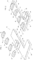
Figures 1-4 show a method for producing a lighting module, -
Figures 5 and 6 are perspective views, from different angles, of a lighting module, -
Figures 7 and 8 are side views of an embodiment of a connector device for a lighting module, -
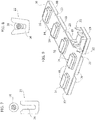
Figure 9 is a perspective view showing an alternative configuration of a printed circuit board for producing a lighting module, and -
Figures 10 and 11 are perspective views of a luminous signage device. - It will be appreciated that, for clarity and simplicity of illustration, the various Figures may not be drawn to the same scale.
- In the following description, various specific details are given to provide a thorough understanding of various exemplary embodiments. The embodiments may be practiced without one or several specific details, or with other methods, components, materials, etc. In other instances, well-known structures, materials or operations are not shown or described in detail in order to avoid obscuring various aspects of the embodiments.
- Reference throughout this specification to "one embodiment" or "an embodiment" means that a particular feature, structure, or characteristic described in connection with the embodiment is included in at least one embodiment. Thus, the possible appearances of the phrases "in one embodiment" or "in an embodiment" in various places throughout this specification are not necessarily all referring exactly to the same embodiment. Furthermore, particular features, structures, or characteristics may be combined in any suitable manner in one or more embodiments.
- The headings provided herein are for convenience only, and therefore do not interpret the extent of protection or scope of the embodiments.
- In
Figure 1 ,reference 10 denotes a planar printed circuit board. The printedcircuit board 10 may have afirst surface 12, on which a plurality of electrically poweredlight radiation sources 14 may be fixed. - The electrically powered
light radiation sources 14 may be solid-state light radiation sources, such as LED sources. Thelight radiation sources 14 may have respectivelight emission surfaces 16, parallel to thefirst surface 12 ofprinted circuit board 10. Thelight radiation sources 14 may be top emission LEDs. - The printed
circuit board 10 may include three or morerigid portions 18, which are mutually connected by means offlexible portions 20. Therigid portions 18 may have a square or rectangular shape. The printedcircuit board 10 may be L-shaped, as shown inFigures 1 and 2 . - The
light radiation sources 14 may be fixed onto respectiverigid portions 18 of the printedcircuit board 10.Connector devices 22 may be fixed onto arigid portion 18 devoid oflight radiation sources 14. The printedcircuit board 10 may also host electrical driving components (not shown) for driving and controlling thelight radiation sources 14. Thelight radiation sources 14, theelectrical connectors 22 and the electronic driving components may be attached to the printedcircuit board 10 by soldering, according to techniques known in the field of production of LED lighting devices. - As shown in
Figures 3 and 4 , in one or more embodiments the printedcircuit board 10 may be folded into a three-dimensional structure 24, having three or moreplanar faces 26 formed by respectiverigid portions 18 of the printedcircuit board 10. The planar faces 26 of the three-dimensional structure 24 may extend around a main axis A. Therigid portion 18 carrying theconnector devices 22 may be orthogonal to the main axis A. Theflexible portions 20 of the printedcircuit board 10 may form rounded corners between theplanar faces 26 of the three-dimensional structure 24. - With reference to
Figure 3 , in one or more embodiments the three-dimensional structure 24 may be folded around arigid support 28 located within the three-dimensional structure 24. The three-dimensional structure 24 may be attached to therigid support 28 e.g. by gluing. Therigid support 28 may have the shape of a three-dimensional solid figure having a polygonal shape, e.g. triangular, square, pentagonal etc. Specifically, in one or more embodiments, the three-dimensional structure 24 may have a cubic or parallelepiped shape, having fourfaces 26 oriented at 90° one with respect to the other. - With reference to
Figure 4 , in one or more embodiments the three-dimensional structure 24 may be encapsulated into apolymeric material 30, which may form an encapsulating layer coating the printedcircuit board 10, thelight radiation sources 14 and other electronic components. Thepolymeric material 30 may be a material adapted to protect thelight radiation sources 14 and other electronic components. The layer ofpolymeric material 30 may be formed by conventional moulding techniques. - In
Figures 5 and 6 ,reference 32 denotes a finished lighting module which may be obtained by means of the method described in the foregoing. Thelighting module 32 may include a planar printedcircuit board 10, which is folded into a three-dimensional structure 24 having three or moreplanar faces 26 extending around a main axis A. - In one or more embodiments, the
lighting module 32 may include three or more electrically poweredlight radiation sources 14, fixed torespective faces 26 of the three-dimensional structure 24. Thelight radiation sources 24 may have respective emission surfaces 16 facing outwards of the three-dimensional structure 24. The light radiation sources may be angularly equidistant from each other in a plane orthogonal to the main axis A, along an angle of 360°. The angular distance between thelight radiation sources 14 may amount to 360°/n, wherein n is the number offaces 26 of the three-dimensional structure 24 parallel to main axis A. - The faces 26 of the three-dimensional structure may be formed by respective
rigid portions 18 of the printedcircuit board 10, which are connected to each other by means offlexible portions 20. - The three-
dimensional structure 24 may be fixed to arigid support 28 located within the three-dimensional structure 24. The three-dimensional structure 24 may include a base 34 orthogonal to the main axis A and carryingconnector devices 22. - In one or more embodiments, the three-
dimensional structure 24 may be encapsulated into apolymeric material 30. - With reference to
Figures 7 and 8 , in one or more embodiments theconnector devices 22 may be IDCs (Insulation-Displacement Connectors) provided with cuttingedges 36, between which aninsulated cable 38 may be inserted. As shown inFigures 7 and 8 , when thecable 38 is inserted between the cutting edges 36 ofcontacts 22, theedges 36 cut the insulating coating ofcable 38 and establish an electrical connection with the conductive portion ofcable 38. - In one or more embodiments, the
lighting module 32 may be devoid of light radiation sources on a surface orthogonal to main axis A opposed tobase 34. - In one or more embodiments, the three-dimensional structure (24) may include three or more planar faces 26 in a plane containing said main axis (A) and carrying respective electrically-powered light radiation sources (14) equidistant from each other. For example, in one or more embodiments the
lighting module 32 may have a face orthogonal to axis A andopposite base 34 carrying alight radiation source 14. In one or more embodiments, this arrangement may be obtained starting from a T-shaped planar printed circuit board, as shown inFigure 9 , which may then be folded so as to form a three-dimensional structure having two opposite faces orthogonal to main axis A. - With reference to
Figures 10 and 11 , one or more embodiments may concern aluminous signage device 40. Thesignage device 40 may be a component of a lighted sign and may have the shape e.g. of a letter or a symbol. Thesignage device 40 may include acasing 42 having acavity 44. In one or more embodiments, thesignage device 40 may include alight emitting wall 46, which may close one side of thecavity 44. - In one or more embodiments, the
cavity 44 of thesignage device 40 may host one ormore lighting modules 32, arranged with the main axis A orthogonal to thelight emitting wall 46. In one or more embodiments, thecavity 44 may have aside wall 48, and thelighting modules 32 may be received withincavity 44 with thefaces 26 of the three-dimensional structure 24 facingside wall 48. - In one or more embodiments, casing 42 may have a
reflective side wall 50. Thereflective side wall 50 may be the outer surface ofcasing 42. Thecavity 44 may also have a bottom wall opposed to thelight emitting wall 46. In one or more embodiments, also the bottom wall ofcavity 44 may be reflective. - In one or more embodiments, the
lighting modules 32 may emit light radiation having a distribution over 360° around the respective main axes A. The light radiation emitted by thelighting modules 32 may be parallel to thelight emitting wall 46 of theluminous signage device 40. The light radiation generated by thelighting modules 32 may be reflected by the reflectiveouter surface 50 and by the bottom wall ofcavity 44. The reflected light radiation may illuminate thelight emitting wall 46 of thesignage device 40 with a uniform distribution. This distribution may avoid or reduce light spots and/or dark areas on thelight emitting wall 46. In one or more embodiments, the light radiation generated by thelighting modules 32 may therefore be mainly directed onto the reflective walls ofcavity 44, without directly illuminating thelight emitting wall 46 of thesignage device 40. - In one or more embodiments, the
lighting modules 32 may be fixed in thecasing 42 of thesignage device 40 by means of an additional encapsulating layer. In one or more embodiments, thelighting modules 32 may be glued to thecasing 42 or to thelight emitting wall 46 of thesignage device 40. - One or more embodiments may offer one or more of the following advantages:
- possibility of a wider spacing between two
consecutive LED modules 32, - possibility of using common top emission LEDs, instead of more expensive side emission LEDs,
- possibility of distributing the light radiation over 360°,
- possibility of changing the distance between the
lighting modules 32, - possibility of varying the length of the cables, in order to avoid floating cables which may originate shadows.
- One or more embodiments may therefore refer to a lighting module including:
- a planar printed circuit board (e.g. 10) folded into a three-dimensional structure (e.g. 24) having three or more planar faces (e.g. 26) extending around a main axis (e.g. A),
- three or more electrically powered light radiation sources (e.g. 14) fixed to respective faces (e.g. 26) of said three-dimensional structure (e.g. 24) and having respective light emission surfaces (e.g. 16) facing outwards of said three-dimensional structure (e.g. 24),
- In one or more embodiments, the three-dimensional structure (e.g. 24) may include three or more faces (e.g. 26) in a plane containing said main axis (e.g. A) and carrying respective electrically powered light radiation sources (e.g. 14) equidistant from each other.
- In one or more embodiments, the printed circuit board (e.g. 10) may include three or more rigid portions (e.g. 18) forming said faces (e.g. 26) and connected together by flexible portions (e.g. 20).
- In one or more embodiments, the three-dimensional structure (e.g. 24) may be fixed to a rigid support (e.g. 28) located within the three-dimensional structure (e.g. 24).
- In one or more embodiments, the three-dimensional structure (e.g. 24) may include a base (e.g. 34) orthogonal to the main axis (e.g. A) and carrying connector devices (e.g. 22).
- In one or more embodiments, the three-dimensional structure (e.g. 24) may include an upper face (e.g. 26) perpendicular to the main axis (e.g. A) and carrying a respective electrically powered light radiation source (e.g. 14).
- In one or more embodiments, the three-dimensional structure (e.g. 24) may be encapsulated in a polymeric material (e.g. 30).
- In one or more embodiments, the light radiation sources (e.g. 14) may be top emission LEDs.
- One or more embodiments may concern a method for producing a lighting module (e.g. 32), including:
- providing a planar printed circuit board (e.g. 10) carrying three or more electrically powered light radiation sources (e.g. 14),
- folding said planar printed circuit board (e.g. 10) into a three-dimensional structure (e.g. 24) having three or more planar faces (e.g. 26) extending around a main axis (e.g. A),
- In one or more embodiments, the method may include attaching the three-dimensional structure (e.g. 24) to a rigid support (e.g. 28) located within said three-dimensional structure (e.g. 24).
- In one or more embodiments, the method may include encapsulating said three-dimensional structure (e.g. 24) into a polymeric material (e.g. 32).
- One or more embodiments may concern a luminous signage device (e.g. 40) including a casing (e.g. 42) having a cavity (e.g. 44) and a light emitting wall (e.g. 46) that covers one side of said cavity (e.g. 44), including one or more lighting modules (e.g. 32) arranged in said cavity (e.g. 44), with said main axis (e.g. A) orthogonal to said light emitting wall (e.g. 46).
- In one or more embodiments, the casing (e.g. 42) may have a reflective side wall (e.g. 50).
- In one or more embodiments, said emitting surfaces (e.g. 16) of said light radiation sources (e.g. 14) may be directed towards a side wall (e.g. 48) of the cavity (e.g. 44) of the casing (e.g. 42).
- Without prejudice to the basic principle, the implementation details and the embodiments may vary, even appreciably, with respect to what has been described herein by way of non-limiting example only, without departing from the extent of protection.
- Said extent of protection is defined by the annexed claims.
LIST OF REFERENCE SIGNS printed circuit board 10 first surface 12 light radiation sources 14 light emission surfaces 16 rigid portions 18 flexible portions 20 connector devices 22 three- dimensional structure 24 planar faces 26 main axis A rigid support 28 polymeric material 30 finished lighting module 32 base 34 cutting edges 36 insulated cable 38 luminous signage device 40 casing 42 cavity 44 light emitting wall 46 side wall 48 reflective sidewall 50
wherein in said three-dimensional structure (e.g. 24) said light radiation sources (e.g. 14) may be angularly equidistant from each other in a plane orthogonal to the main axis (e.g. A) along an angle of 360°.
Claims (14)
- A lighting module comprising:- a planar printed circuit (10) folded into a three-dimensional structure (24) having three or more planar faces (26) extending around a main axis (A),- three or more electrically powered light radiation sources (14) fixed to respective faces (26) of said three-dimensional structure (24) and having respective light emitting surfaces (16) facing outwards of said three-dimensional structure (24),wherein the light radiation sources (14) are angularly equidistant from each other in a plane orthogonal to said main axis (A) along an angle of 360°.
- A lighting module according to claim 1, wherein said three-dimensional structure (24) comprises three or more planar faces (26) in a plane containing said main axis (A) and carrying respective electrically powered light radiation sources (14) equidistant from each other.
- A lighting module according to any one of the preceding claims, wherein said printed circuit board (10) comprises three or more rigid portions (18) forming said faces (26) and connected together by flexible portions (20).
- A lighting module according to any one of the preceding claims, wherein said three-dimensional structure (24) is fixed to a rigid support (28) located within the three-dimensional structure (24).
- A lighting module according to any one of the preceding claims, wherein said three-dimensional structure (24) comprises a base (34) orthogonal to said main axis (A) and carrying connector devices (22).
- A lighting module according to any one of the preceding claims, wherein said three-dimensional structure (24) comprises an upper face (26) perpendicular to said main axis (A) and carrying a respective electrically powered source of light radiation (14).
- A lighting module according to any one of the preceding claims, wherein said three-dimensional structure (24) is encapsulated in a polymeric material (30).
- A lighting module according to any one of the preceding claims, wherein said light radiation sources (14) are top emission LED.
- A process for producing a lighting module (32), comprising:- providing a planar printed circuit board (10) carrying three or more electrically powered light radiation sources (14),- folding said planar printed circuit board (10) in a three-dimensional structure (24) having three or more planar faces (26) extending around a main axis (A),wherein said light radiation sources (14) are fixed to respective faces (26) and have respective emission surfaces (16) facing outwards of said three-dimensional structure (24), and
wherein in said three-dimensional structure (24) said light radiation sources (14) are angularly equidistant from each other in a plane orthogonal to said main axis (A) along an angle of 360 °. - A method according to claim 9, comprising attaching said three-dimensional structure (24) to a rigid support (28) located within said three-dimensional structure (24).
- A method according to claim 9 or claim 10, comprising encapsulating said three-dimensional structure (24) in a polymeric material (32).
- A luminous signage device (40) comprising a casing (42) having a cavity (44) and a light emitting wall (46) that covers one side of said cavity (44), comprising one or more lighting modules (32) according to one or more of claims 1-8 disposed in said cavity (44) with said main axis (A) orthogonal to said light emitting wall (46).
- A luminous signage device (40) according to claim 11, wherein said casing (42) has at least one reflective sidewall (50).
- A luminous signage device (40) according to claim 13, wherein said emitting surfaces (16) of said light radiation sources (14) are directed toward said side wall (50).
Applications Claiming Priority (1)
| Application Number | Priority Date | Filing Date | Title |
|---|---|---|---|
| IT201700045168 | 2017-04-26 |
Publications (2)
| Publication Number | Publication Date |
|---|---|
| EP3399230A1 true EP3399230A1 (en) | 2018-11-07 |
| EP3399230B1 EP3399230B1 (en) | 2022-05-25 |
Family
ID=59811837
Family Applications (1)
| Application Number | Title | Priority Date | Filing Date |
|---|---|---|---|
| EP18168072.9A Active EP3399230B1 (en) | 2017-04-26 | 2018-04-18 | Lighting module, method for manufacturing the same and luminous signage device comprising such lighting module |
Country Status (1)
| Country | Link |
|---|---|
| EP (1) | EP3399230B1 (en) |
Citations (7)
| Publication number | Priority date | Publication date | Assignee | Title |
|---|---|---|---|---|
| DE10350913A1 (en) * | 2003-10-31 | 2005-06-02 | Osram Opto Semiconductors Gmbh | Light-emitting diode arrangement for a rotating warning light comprises a spatial arrangement of diodes, a support having rigid assembly regions and connecting regions arranged between the assembly regions, and a flexible circuit board |
| EP2295849A1 (en) * | 2009-09-09 | 2011-03-16 | Peugeot Citroën Automobiles SA | Vehicle light |
| GB2485745A (en) * | 2009-09-27 | 2012-05-23 | Dongguan Light Source Opto Tech Co Ltd | LED device for three-dimensional illumination |
| US20120238045A1 (en) * | 2010-12-22 | 2012-09-20 | E. I. Du Pont De Nemours And Company | Three dimensional light emitting diode systems, and compositions and methods relating thereto |
| US20130062631A1 (en) * | 2011-09-13 | 2013-03-14 | Lustrous Green Technology Of Lighting | Light emitting structure, light emitting module, and light emitting device |
| EP2722589A2 (en) * | 2012-10-16 | 2014-04-23 | The Sloan Company, Inc. dba Sloanled | Angled emitter channel letter lighting |
| US20160178166A1 (en) * | 2013-08-09 | 2016-06-23 | Sumitomo Electric Industries, Ltd. | Led module and led lighting fixture |
-
2018
- 2018-04-18 EP EP18168072.9A patent/EP3399230B1/en active Active
Patent Citations (7)
| Publication number | Priority date | Publication date | Assignee | Title |
|---|---|---|---|---|
| DE10350913A1 (en) * | 2003-10-31 | 2005-06-02 | Osram Opto Semiconductors Gmbh | Light-emitting diode arrangement for a rotating warning light comprises a spatial arrangement of diodes, a support having rigid assembly regions and connecting regions arranged between the assembly regions, and a flexible circuit board |
| EP2295849A1 (en) * | 2009-09-09 | 2011-03-16 | Peugeot Citroën Automobiles SA | Vehicle light |
| GB2485745A (en) * | 2009-09-27 | 2012-05-23 | Dongguan Light Source Opto Tech Co Ltd | LED device for three-dimensional illumination |
| US20120238045A1 (en) * | 2010-12-22 | 2012-09-20 | E. I. Du Pont De Nemours And Company | Three dimensional light emitting diode systems, and compositions and methods relating thereto |
| US20130062631A1 (en) * | 2011-09-13 | 2013-03-14 | Lustrous Green Technology Of Lighting | Light emitting structure, light emitting module, and light emitting device |
| EP2722589A2 (en) * | 2012-10-16 | 2014-04-23 | The Sloan Company, Inc. dba Sloanled | Angled emitter channel letter lighting |
| US20160178166A1 (en) * | 2013-08-09 | 2016-06-23 | Sumitomo Electric Industries, Ltd. | Led module and led lighting fixture |
Also Published As
| Publication number | Publication date |
|---|---|
| EP3399230B1 (en) | 2022-05-25 |
Similar Documents
| Publication | Publication Date | Title |
|---|---|---|
| US9074758B2 (en) | Interlocking light sheet tiles | |
| JP5462379B2 (en) | LED3D curved lead frame for light emitting device | |
| US9109765B2 (en) | Lighting module, lighting strip including a plurality of contiguous lighting modules, and method for preparing a lighting strip | |
| EP2716959B1 (en) | Light emitting device | |
| US10295123B2 (en) | Bulb apparatus and manufacturing method thereof | |
| EP3788419B1 (en) | Light fixture with dynamically controllable light distribution | |
| US20200166182A1 (en) | Substrate for led packaging, led package, and led bulb | |
| US20130077300A1 (en) | Display box lighting module | |
| US7339157B2 (en) | Illumination device | |
| US20140111992A1 (en) | Leadframe-based surface mount technology segmented display design and method of manufacture | |
| CN104798118B (en) | signal column | |
| US20150009673A1 (en) | Illumination device | |
| EP2722589B1 (en) | Angled emitter channel letter lighting | |
| US20130062631A1 (en) | Light emitting structure, light emitting module, and light emitting device | |
| US9982859B2 (en) | Light emitting diode, and headlamp and signal lamp having the same | |
| EP3399230B1 (en) | Lighting module, method for manufacturing the same and luminous signage device comprising such lighting module | |
| KR20120026767A (en) | Led lighting device and manufacturing method thereof | |
| CN104456472A (en) | Light emitting device and light source module thereof | |
| KR101480961B1 (en) | LED lighting board consisting of transparent plastic and method for manufacturing thereof | |
| US9004719B2 (en) | Trim cap illuminated channel letter lighting system and letter construction system | |
| CN203907349U (en) | Waterproof backlight module with lenses | |
| CN110998173A (en) | Flexible Lighting System | |
| US8356917B2 (en) | Light source | |
| JP2006058828A (en) | Display device and light source thereof | |
| CN203413435U (en) | LED (light-emitting diode) module and lighting device |
Legal Events
| Date | Code | Title | Description |
|---|---|---|---|
| PUAI | Public reference made under article 153(3) epc to a published international application that has entered the european phase |
Free format text: ORIGINAL CODE: 0009012 |
|
| STAA | Information on the status of an ep patent application or granted ep patent |
Free format text: STATUS: THE APPLICATION HAS BEEN PUBLISHED |
|
| AK | Designated contracting states |
Kind code of ref document: A1 Designated state(s): AL AT BE BG CH CY CZ DE DK EE ES FI FR GB GR HR HU IE IS IT LI LT LU LV MC MK MT NL NO PL PT RO RS SE SI SK SM TR |
|
| AX | Request for extension of the european patent |
Extension state: BA ME |
|
| STAA | Information on the status of an ep patent application or granted ep patent |
Free format text: STATUS: REQUEST FOR EXAMINATION WAS MADE |
|
| 17P | Request for examination filed |
Effective date: 20190417 |
|
| RBV | Designated contracting states (corrected) |
Designated state(s): AL AT BE BG CH CY CZ DE DK EE ES FI FR GB GR HR HU IE IS IT LI LT LU LV MC MK MT NL NO PL PT RO RS SE SI SK SM TR |
|
| RAP1 | Party data changed (applicant data changed or rights of an application transferred) |
Owner name: OSRAM S.P.A. - SOCIETA' RIUNITE OSRAM EDISON CLERICI Owner name: OSRAM GMBH |
|
| RAP3 | Party data changed (applicant data changed or rights of an application transferred) |
Owner name: OSRAM GMBH Owner name: OSRAM S.P.A. - SOCIETA' RIUNITE OSRAM EDISON CLERICI |
|
| STAA | Information on the status of an ep patent application or granted ep patent |
Free format text: STATUS: EXAMINATION IS IN PROGRESS |
|
| 17Q | First examination report despatched |
Effective date: 20210816 |
|
| RIC1 | Information provided on ipc code assigned before grant |
Ipc: F21Y 107/30 20160101ALN20211029BHEP Ipc: F21Y 107/40 20160101ALN20211029BHEP Ipc: F21Y 107/70 20160101ALN20211029BHEP Ipc: G09F 13/04 20060101ALI20211029BHEP Ipc: F21V 21/002 20060101AFI20211029BHEP |
|
| GRAP | Despatch of communication of intention to grant a patent |
Free format text: ORIGINAL CODE: EPIDOSNIGR1 |
|
| STAA | Information on the status of an ep patent application or granted ep patent |
Free format text: STATUS: GRANT OF PATENT IS INTENDED |
|
| RIC1 | Information provided on ipc code assigned before grant |
Ipc: F21Y 107/30 20160101ALN20211124BHEP Ipc: F21Y 107/40 20160101ALN20211124BHEP Ipc: F21Y 107/70 20160101ALN20211124BHEP Ipc: G09F 13/04 20060101ALI20211124BHEP Ipc: F21V 21/002 20060101AFI20211124BHEP |
|
| INTG | Intention to grant announced |
Effective date: 20211220 |
|
| GRAS | Grant fee paid |
Free format text: ORIGINAL CODE: EPIDOSNIGR3 |
|
| GRAA | (expected) grant |
Free format text: ORIGINAL CODE: 0009210 |
|
| STAA | Information on the status of an ep patent application or granted ep patent |
Free format text: STATUS: THE PATENT HAS BEEN GRANTED |
|
| AK | Designated contracting states |
Kind code of ref document: B1 Designated state(s): AL AT BE BG CH CY CZ DE DK EE ES FI FR GB GR HR HU IE IS IT LI LT LU LV MC MK MT NL NO PL PT RO RS SE SI SK SM TR |
|
| REG | Reference to a national code |
Ref country code: GB Ref legal event code: FG4D |
|
| REG | Reference to a national code |
Ref country code: CH Ref legal event code: EP |
|
| REG | Reference to a national code |
Ref country code: AT Ref legal event code: REF Ref document number: 1494392 Country of ref document: AT Kind code of ref document: T Effective date: 20220615 Ref country code: DE Ref legal event code: R096 Ref document number: 602018035916 Country of ref document: DE |
|
| REG | Reference to a national code |
Ref country code: IE Ref legal event code: FG4D |
|
| REG | Reference to a national code |
Ref country code: LT Ref legal event code: MG9D |
|
| REG | Reference to a national code |
Ref country code: NL Ref legal event code: MP Effective date: 20220525 |
|
| REG | Reference to a national code |
Ref country code: AT Ref legal event code: MK05 Ref document number: 1494392 Country of ref document: AT Kind code of ref document: T Effective date: 20220525 |
|
| PG25 | Lapsed in a contracting state [announced via postgrant information from national office to epo] |
Ref country code: SE Free format text: LAPSE BECAUSE OF FAILURE TO SUBMIT A TRANSLATION OF THE DESCRIPTION OR TO PAY THE FEE WITHIN THE PRESCRIBED TIME-LIMIT Effective date: 20220525 Ref country code: PT Free format text: LAPSE BECAUSE OF FAILURE TO SUBMIT A TRANSLATION OF THE DESCRIPTION OR TO PAY THE FEE WITHIN THE PRESCRIBED TIME-LIMIT Effective date: 20220926 Ref country code: NO Free format text: LAPSE BECAUSE OF FAILURE TO SUBMIT A TRANSLATION OF THE DESCRIPTION OR TO PAY THE FEE WITHIN THE PRESCRIBED TIME-LIMIT Effective date: 20220825 Ref country code: NL Free format text: LAPSE BECAUSE OF FAILURE TO SUBMIT A TRANSLATION OF THE DESCRIPTION OR TO PAY THE FEE WITHIN THE PRESCRIBED TIME-LIMIT Effective date: 20220525 Ref country code: LT Free format text: LAPSE BECAUSE OF FAILURE TO SUBMIT A TRANSLATION OF THE DESCRIPTION OR TO PAY THE FEE WITHIN THE PRESCRIBED TIME-LIMIT Effective date: 20220525 Ref country code: HR Free format text: LAPSE BECAUSE OF FAILURE TO SUBMIT A TRANSLATION OF THE DESCRIPTION OR TO PAY THE FEE WITHIN THE PRESCRIBED TIME-LIMIT Effective date: 20220525 Ref country code: GR Free format text: LAPSE BECAUSE OF FAILURE TO SUBMIT A TRANSLATION OF THE DESCRIPTION OR TO PAY THE FEE WITHIN THE PRESCRIBED TIME-LIMIT Effective date: 20220826 Ref country code: FI Free format text: LAPSE BECAUSE OF FAILURE TO SUBMIT A TRANSLATION OF THE DESCRIPTION OR TO PAY THE FEE WITHIN THE PRESCRIBED TIME-LIMIT Effective date: 20220525 Ref country code: ES Free format text: LAPSE BECAUSE OF FAILURE TO SUBMIT A TRANSLATION OF THE DESCRIPTION OR TO PAY THE FEE WITHIN THE PRESCRIBED TIME-LIMIT Effective date: 20220525 Ref country code: BG Free format text: LAPSE BECAUSE OF FAILURE TO SUBMIT A TRANSLATION OF THE DESCRIPTION OR TO PAY THE FEE WITHIN THE PRESCRIBED TIME-LIMIT Effective date: 20220825 Ref country code: AT Free format text: LAPSE BECAUSE OF FAILURE TO SUBMIT A TRANSLATION OF THE DESCRIPTION OR TO PAY THE FEE WITHIN THE PRESCRIBED TIME-LIMIT Effective date: 20220525 |
|
| PG25 | Lapsed in a contracting state [announced via postgrant information from national office to epo] |
Ref country code: RS Free format text: LAPSE BECAUSE OF FAILURE TO SUBMIT A TRANSLATION OF THE DESCRIPTION OR TO PAY THE FEE WITHIN THE PRESCRIBED TIME-LIMIT Effective date: 20220525 Ref country code: PL Free format text: LAPSE BECAUSE OF FAILURE TO SUBMIT A TRANSLATION OF THE DESCRIPTION OR TO PAY THE FEE WITHIN THE PRESCRIBED TIME-LIMIT Effective date: 20220525 Ref country code: LV Free format text: LAPSE BECAUSE OF FAILURE TO SUBMIT A TRANSLATION OF THE DESCRIPTION OR TO PAY THE FEE WITHIN THE PRESCRIBED TIME-LIMIT Effective date: 20220525 Ref country code: IS Free format text: LAPSE BECAUSE OF FAILURE TO SUBMIT A TRANSLATION OF THE DESCRIPTION OR TO PAY THE FEE WITHIN THE PRESCRIBED TIME-LIMIT Effective date: 20220925 |
|
| PG25 | Lapsed in a contracting state [announced via postgrant information from national office to epo] |
Ref country code: SM Free format text: LAPSE BECAUSE OF FAILURE TO SUBMIT A TRANSLATION OF THE DESCRIPTION OR TO PAY THE FEE WITHIN THE PRESCRIBED TIME-LIMIT Effective date: 20220525 Ref country code: SK Free format text: LAPSE BECAUSE OF FAILURE TO SUBMIT A TRANSLATION OF THE DESCRIPTION OR TO PAY THE FEE WITHIN THE PRESCRIBED TIME-LIMIT Effective date: 20220525 Ref country code: RO Free format text: LAPSE BECAUSE OF FAILURE TO SUBMIT A TRANSLATION OF THE DESCRIPTION OR TO PAY THE FEE WITHIN THE PRESCRIBED TIME-LIMIT Effective date: 20220525 Ref country code: EE Free format text: LAPSE BECAUSE OF FAILURE TO SUBMIT A TRANSLATION OF THE DESCRIPTION OR TO PAY THE FEE WITHIN THE PRESCRIBED TIME-LIMIT Effective date: 20220525 Ref country code: DK Free format text: LAPSE BECAUSE OF FAILURE TO SUBMIT A TRANSLATION OF THE DESCRIPTION OR TO PAY THE FEE WITHIN THE PRESCRIBED TIME-LIMIT Effective date: 20220525 Ref country code: CZ Free format text: LAPSE BECAUSE OF FAILURE TO SUBMIT A TRANSLATION OF THE DESCRIPTION OR TO PAY THE FEE WITHIN THE PRESCRIBED TIME-LIMIT Effective date: 20220525 |
|
| REG | Reference to a national code |
Ref country code: DE Ref legal event code: R097 Ref document number: 602018035916 Country of ref document: DE |
|
| PG25 | Lapsed in a contracting state [announced via postgrant information from national office to epo] |
Ref country code: AL Free format text: LAPSE BECAUSE OF FAILURE TO SUBMIT A TRANSLATION OF THE DESCRIPTION OR TO PAY THE FEE WITHIN THE PRESCRIBED TIME-LIMIT Effective date: 20220525 |
|
| PLBE | No opposition filed within time limit |
Free format text: ORIGINAL CODE: 0009261 |
|
| STAA | Information on the status of an ep patent application or granted ep patent |
Free format text: STATUS: NO OPPOSITION FILED WITHIN TIME LIMIT |
|
| 26N | No opposition filed |
Effective date: 20230228 |
|
| PG25 | Lapsed in a contracting state [announced via postgrant information from national office to epo] |
Ref country code: SI Free format text: LAPSE BECAUSE OF FAILURE TO SUBMIT A TRANSLATION OF THE DESCRIPTION OR TO PAY THE FEE WITHIN THE PRESCRIBED TIME-LIMIT Effective date: 20220525 |
|
| REG | Reference to a national code |
Ref country code: DE Ref legal event code: R081 Ref document number: 602018035916 Country of ref document: DE Owner name: OPTOTRONIC GMBH, DE Free format text: FORMER OWNER: OSRAM GMBH, 80807 MUENCHEN, DE Ref country code: DE Ref legal event code: R081 Ref document number: 602018035916 Country of ref document: DE Owner name: INVENTRONICS GMBH, DE Free format text: FORMER OWNER: OSRAM GMBH, 80807 MUENCHEN, DE |
|
| REG | Reference to a national code |
Ref country code: CH Ref legal event code: PL |
|
| GBPC | Gb: european patent ceased through non-payment of renewal fee |
Effective date: 20230418 |
|
| PG25 | Lapsed in a contracting state [announced via postgrant information from national office to epo] |
Ref country code: LU Free format text: LAPSE BECAUSE OF NON-PAYMENT OF DUE FEES Effective date: 20230418 |
|
| REG | Reference to a national code |
Ref country code: BE Ref legal event code: MM Effective date: 20230430 |
|
| PG25 | Lapsed in a contracting state [announced via postgrant information from national office to epo] |
Ref country code: MC Free format text: LAPSE BECAUSE OF FAILURE TO SUBMIT A TRANSLATION OF THE DESCRIPTION OR TO PAY THE FEE WITHIN THE PRESCRIBED TIME-LIMIT Effective date: 20220525 |
|
| PG25 | Lapsed in a contracting state [announced via postgrant information from national office to epo] |
Ref country code: GB Free format text: LAPSE BECAUSE OF NON-PAYMENT OF DUE FEES Effective date: 20230418 |
|
| PG25 | Lapsed in a contracting state [announced via postgrant information from national office to epo] |
Ref country code: MC Free format text: LAPSE BECAUSE OF FAILURE TO SUBMIT A TRANSLATION OF THE DESCRIPTION OR TO PAY THE FEE WITHIN THE PRESCRIBED TIME-LIMIT Effective date: 20220525 Ref country code: LI Free format text: LAPSE BECAUSE OF NON-PAYMENT OF DUE FEES Effective date: 20230430 Ref country code: IT Free format text: LAPSE BECAUSE OF FAILURE TO SUBMIT A TRANSLATION OF THE DESCRIPTION OR TO PAY THE FEE WITHIN THE PRESCRIBED TIME-LIMIT Effective date: 20220525 Ref country code: GB Free format text: LAPSE BECAUSE OF NON-PAYMENT OF DUE FEES Effective date: 20230418 Ref country code: FR Free format text: LAPSE BECAUSE OF NON-PAYMENT OF DUE FEES Effective date: 20230430 Ref country code: CH Free format text: LAPSE BECAUSE OF NON-PAYMENT OF DUE FEES Effective date: 20230430 |
|
| REG | Reference to a national code |
Ref country code: IE Ref legal event code: MM4A |
|
| PG25 | Lapsed in a contracting state [announced via postgrant information from national office to epo] |
Ref country code: BE Free format text: LAPSE BECAUSE OF NON-PAYMENT OF DUE FEES Effective date: 20230430 |
|
| PG25 | Lapsed in a contracting state [announced via postgrant information from national office to epo] |
Ref country code: IE Free format text: LAPSE BECAUSE OF NON-PAYMENT OF DUE FEES Effective date: 20230418 |
|
| PG25 | Lapsed in a contracting state [announced via postgrant information from national office to epo] |
Ref country code: IE Free format text: LAPSE BECAUSE OF NON-PAYMENT OF DUE FEES Effective date: 20230418 |
|
| REG | Reference to a national code |
Ref country code: DE Ref legal event code: R081 Ref document number: 602018035916 Country of ref document: DE Owner name: INVENTRONICS GMBH, DE Free format text: FORMER OWNER: OPTOTRONIC GMBH, 85748 GARCHING, DE |
|
| PGFP | Annual fee paid to national office [announced via postgrant information from national office to epo] |
Ref country code: DE Payment date: 20240418 Year of fee payment: 7 |
|
| PG25 | Lapsed in a contracting state [announced via postgrant information from national office to epo] |
Ref country code: BG Free format text: LAPSE BECAUSE OF FAILURE TO SUBMIT A TRANSLATION OF THE DESCRIPTION OR TO PAY THE FEE WITHIN THE PRESCRIBED TIME-LIMIT Effective date: 20220525 |
|
| PG25 | Lapsed in a contracting state [announced via postgrant information from national office to epo] |
Ref country code: BG Free format text: LAPSE BECAUSE OF FAILURE TO SUBMIT A TRANSLATION OF THE DESCRIPTION OR TO PAY THE FEE WITHIN THE PRESCRIBED TIME-LIMIT Effective date: 20220525 |
|
| PG25 | Lapsed in a contracting state [announced via postgrant information from national office to epo] |
Ref country code: CY Free format text: LAPSE BECAUSE OF FAILURE TO SUBMIT A TRANSLATION OF THE DESCRIPTION OR TO PAY THE FEE WITHIN THE PRESCRIBED TIME-LIMIT; INVALID AB INITIO Effective date: 20180418 |
|
| PG25 | Lapsed in a contracting state [announced via postgrant information from national office to epo] |
Ref country code: HU Free format text: LAPSE BECAUSE OF FAILURE TO SUBMIT A TRANSLATION OF THE DESCRIPTION OR TO PAY THE FEE WITHIN THE PRESCRIBED TIME-LIMIT; INVALID AB INITIO Effective date: 20180418 |
|
| REG | Reference to a national code |
Ref country code: DE Ref legal event code: R119 Ref document number: 602018035916 Country of ref document: DE |
|
| PG25 | Lapsed in a contracting state [announced via postgrant information from national office to epo] |
Ref country code: TR Free format text: LAPSE BECAUSE OF FAILURE TO SUBMIT A TRANSLATION OF THE DESCRIPTION OR TO PAY THE FEE WITHIN THE PRESCRIBED TIME-LIMIT Effective date: 20220525 |
|
| PG25 | Lapsed in a contracting state [announced via postgrant information from national office to epo] |
Ref country code: DE Free format text: LAPSE BECAUSE OF NON-PAYMENT OF DUE FEES Effective date: 20251104 |