EP3399201B1 - Improved carabiner system - Google Patents
Improved carabiner system Download PDFInfo
- Publication number
- EP3399201B1 EP3399201B1 EP18169755.8A EP18169755A EP3399201B1 EP 3399201 B1 EP3399201 B1 EP 3399201B1 EP 18169755 A EP18169755 A EP 18169755A EP 3399201 B1 EP3399201 B1 EP 3399201B1
- Authority
- EP
- European Patent Office
- Prior art keywords
- region
- gate
- frame
- key
- carabiner
- Prior art date
- Legal status (The legal status is an assumption and is not a legal conclusion. Google has not performed a legal analysis and makes no representation as to the accuracy of the status listed.)
- Active
Links
Images


Classifications
-
- F—MECHANICAL ENGINEERING; LIGHTING; HEATING; WEAPONS; BLASTING
- F16—ENGINEERING ELEMENTS AND UNITS; GENERAL MEASURES FOR PRODUCING AND MAINTAINING EFFECTIVE FUNCTIONING OF MACHINES OR INSTALLATIONS; THERMAL INSULATION IN GENERAL
- F16B—DEVICES FOR FASTENING OR SECURING CONSTRUCTIONAL ELEMENTS OR MACHINE PARTS TOGETHER, e.g. NAILS, BOLTS, CIRCLIPS, CLAMPS, CLIPS OR WEDGES; JOINTS OR JOINTING
- F16B45/00—Hooks; Eyes
- F16B45/02—Hooks with pivoting or elastically bending closing member
- F16B45/036—Hooks with pivoting or elastically bending closing member with an elastically bending closing member
Definitions
- the invention generally relates to mechanical coupling mechanisms such as carabiners, karabiners, and snap-hooks.
- the invention relates to an improved carabiner gate system and method of operation.
- Carabiners, karabiners, snap-hooks, and releasable clamps are used in a variety of applications for releasably coupling objects to one another.
- a rock climber may use one or more carabiners to releasably secure a rope to a protection device during vertical ascension.
- Carabiners generally include a frame, a gate, and a releasable gate closure mechanism.
- the gate is configured to releasably engage the frame so as to form a continuous inner region which can mechanically couple to one or more objects.
- the releasable gate closure mechanism is configured to allow the gate to be selectively pivoted with respect to the frame in order to facilitate addition or removal of items from the continuous inner region.
- the releasable gate closure mechanism simultaneously biases the gate toward a closed configuration with respect to the frame so as to maintain mechanical coupling of items within the continuous inner region.
- a wide variety of frame, gate, and biasing systems exist to specifically accommodate particular applications and/or manufacturing costs for the carabiner.
- Wire-gate type carabiners represent a particular gate construction, biasing system, and gate-frame interface.
- Wire-gate type carabiners for example are known from JP 2001 020936 and US 2009/000086 A1 .
- Wire-gate carabiners utilize a substantially elongated, looped rigid wire member for the gate portion of the carabiner system.
- a wire member is substantially an elongated metal structure with a circular cross-sectional shape. In general, the lengthwise ends of the wire member gate are oppositely coupled to the frame such that the spring/rebound rigidity of the gate creates the automatic biasing mechanism.
- the frame includes a gate interface region which generally includes a hook over which the loop of the gate is configured to extend while in the closed configuration.
- the reliable positioning of the loop with respect to the hook significantly affects the structural ability of the carabiner to counteract shear forces. Due to the inherent minimal gate thickness, wire-gate type carabiners are usually lighter in overall weight compared to other carabiners. However, the unique requirements and limitations of the gate/frame interface have resulted in an inability to manufacture wire-gate type carabiners for certain applications.
- a variety of specialized carabiner designs are configured to include specific mechanical characteristics that optimize particular functionalities.
- One type of specialized carabiner includes a hookless or keyed engagement coupling scheme between the gate and frame when in the closed configuration. This type of gate/frame engagement scheme optimizes the engagement and disengagement of the carabiner with particular items such as a bolt hanger or a non-sling protection device.
- One example of such a specialized carabiner is disclosed in FR 2807329 A1 .
- structural modifications must be incorporated into the gate/frame interface to maintain the necessary reliable coupling between the gate and frame in the closed configuration. For example, some form of three-dimensional keyed interface must generally be incorporated to provide the necessary engagement between the gate and frame.
- the three-dimensional keyed interface increases the reliability of the coupling between the gate and frame without the introduction of a hook structure.
- Various problems exist with conventional hookless carabiners including manufacturing cost, susceptibility to debris-related obstruction, durability, and weight.
- Another carabiner system is known from 100 813 S.
- a carabiner system according to claim 1 is provided. It particularly relates to an improved carabiner gate system and method of operation.
- the carabiner system includes a frame and a gate.
- the frame includes an opening between a pivot region and a keyed region.
- the keyed region of the frame may be hookless.
- the gate is pivotably coupled to the frame across the opening to form a continuously enclosed inner region in the closed configuration.
- the gate is also pivotably coupled about the pivot region of the frame, forming a gap between the gate and frame in an open configuration.
- the gate further includes a key-lock region, a gate region, and an attachment region which are integrally formed together without any type of coupling between regions.
- the gate region includes a plurality of elongated members between the key-lock region and attachment region.
- the plurality of elongated members may include non-circular cross sections and varying thicknesses and tolerances designed to optimize functionality, weight, and appearance.
- Alternative embodiments include unique methods of operation and manufacturing.
- Embodiments of the present invention represent a significant advance in the field of carabiner systems by combining the functional advantages of hookless coupling between the gate and frame with an optimal integral single component gate.
- Comparable conventional key-lock carabiner gates generally require multi component gate systems with compression couplings or internal springs.
- Embodiments of the present invention minimize gate components and avoid coupling weaknesses between gate regions by providing a unique integral gate shape that inherently includes the respective regions for spring biasing, gate structure, and releasable hookless frame coupling.
- a carabiner system according to claim 1 is provided. It particularly relates to an improved carabiner gate system and method of operation.
- the carabiner system includes a frame and a gate.
- the frame includes an opening between a pivot region and a keyed region.
- the keyed region of the frame may be hookless.
- the gate is pivotably coupled to the frame across the opening to form a continuously enclosed inner region in the closed configuration.
- the gate is also pivotably coupled about the pivot region of the frame, forming a gap between the gate and frame in an open configuration.
- the gate further includes a key-lock region, a gate region, and an attachment region which are integrally formed together without any type of coupling between regions.
- the gate region includes a plurality of elongated members between the key-lock region and attachment region.
- the plurality of elongated members may include non-circular cross sections and varying thicknesses and tolerances designed to optimize functionality, weight, and appearance. Also, while embodiments are described in reference to a carabiner gate system, it will be appreciated that the teachings of the present invention are applicable to other areas including but not limited to methods of operation, methods of manufacturing, etc.
- Integral - A plurality of regions formed together without any type of coupling therebetween.
- a conventional paperclip has multiple parallel regions without any type of coupling therebetween.
- Molded - a member being formed of a single three-dimensional mold.
- a molded member may include specific sub-regions having particular shapes and functions.
- a traditional paperclip is a molded metal structure that does not include any form of couplings between the regions.
- Hookless - a type of carabiner-gate coupling that does not include any type of hook oriented toward the interior of the enclosed carabiner frame.
- Wireless - a structure that is composed of one or more materials that does not include a metal wire.
- Pivotably coupled - two components that are coupled in a manner that enables a pivotal movement therebetween.
- Continuously enclosed region - a two-dimensional region which is enclosed within a substantially continuous structure.
- FIGS 1A-C illustrate a carabiner system in the closed ( Figure 1A ) and open configurations ( Figures 1B-C ), designated generally at 100.
- the system 100 includes frame 150 and a gate 110 which are pivotably intercoupled in both open and closed configurations.
- a continuously enclosed inner region 102 is formed within the frame 150 and gate 110 in the closed configuration ( Figure 1A ).
- the continuously enclosed inner region 102 is a substantially two dimensional region enclosed by a mathematically continuous structure (gate and frame).
- a gap 104 is formed between a portion of the gate 110 and frame 150 in the open configuration ( Figures 1B-C ).
- the gap 104 may further be defined as a separation distance between the gate 110 and frame 150.
- the frame 150 is a substantially C-shaped structure with a spine region 170 and an opening 190 between a pivot region 160 and a keyed region 180.
- the frame may be composed of one or more materials, including but not limited to metals and coatings.
- the frame may include various well known cross sectional shapes so as to optimize weight and strength characteristics, including but not limited to I-beam. It will be appreciated that the various carabiner gate systems discussed in this application may be practiced with a wide variety of carabiner frame structures, styles, and shapes.
- the keyed region 180 may include a flat parallel region 182 and an orthogonal expanded region 184 as shown in Figure 1C .
- neither the flat 182 nor expanded regions 184 include any form of hook facing the interior; therefore, the carabiner system 100 may be referred to as hookless. Rather, the combined shape of the flat and expanded regions 182, 184 form a specific male type coupler configured to interface with a correspondingly female shaped region on the gate (discussed below). The male-female hookless coupling between the gate 110 and the frame 150 creates the necessary operational closed-loop functional strengths in the closed configuration.
- the gate 110 includes an attachment region 120, a gate region 130, and a key-lock region 140.
- the gate 110 is a critical component which may also be referred to as an integral, molded, and/or single-piece member because there are no couplings, unions, or discontinuities between the defined regions of the gate 110. This unique integral nature of the gate 110 provides numerous functional and manufacturing advantages over conventional multi-component or coupled carabiner gate systems.
- the attachment region 120 of the gate 110 is pivotably coupled to the pivot region 160 of the frame 150 via two substantially orthogonal rotating members 122.
- the orthogonal rotating members may include circular cross-sectional shapes and may extend into corresponding recesses on the pivot region 160 of the frame 150.
- the specific independent and offset positioning/orientation of the coupling between the attachment region 120 and the frame 150 in part creates the biasing system which urges the gate 110 towards the closed configuration with respect to the frame 150.
- the urging of the gate 110 towards the closed configuration may also be described as generating a biasing force which corresponds to the gap 104 distance between the gate 110 and the frame 150.
- the biasing force may also correspond to the composition and shape of the gate 110, which include a metal material shaped to create the malleable compliant spring functionalities.
- the gate region 130 may include two elongated members 132 as shown in the illustrated embodiments.
- the elongated members may include non-circular cross-sectional shaped regions and/or discontinuous thickness regions.
- the elongated members 132 may include oval, rectangular, and/or other non-circular cross-sectional shapes between the attachment region 120 and the key-lock region 140.
- portions of the gate region 130 may include increased or decreased (discontinuous) thicknesses or densities so as to optimize structural integrity, user operation, and/or biasing.
- the key-lock region 140 includes a first smaller recess 144 and a second larger recess 146 corresponding to the keyed region of the frame (See Figure 2A ).
- the first smaller recess 144 and second larger recess 146 may also be described as defining a partially enclosed three dimensional concave region 142 (See Figure 2D ).
- the illustrated key-lock region 140 includes an externally defined orthogonal substantially rectangular U-shaped region between the elongated members of the gate region ( Figures 2B-D ).
- the external U-shaped region defines the first smaller recess 144 corresponding to the flat region 182 of the keyed region 180 of the frame 150 and the second larger recess 146 corresponding to the expanded region 184 of the keyed region 180 of the frame 150.
- Figures 3A-C illustrate alternative perspective views of the carabiner system in the closed configuration, designated generally at 100.
- a user may selectively transition the carabiner system 100 from the biased default closed configuration ( Figure 1A ) to the open configuration ( Figure 1B-C ) by continuously exerting an opening force 200 ( Figures 1B-C ) upon the gate 110 with respect to the frame 150.
- the opening force 200 must exceed the biasing force of the biasing system discussed above.
- the opening force 200 must be maintained in order to maintain the open configuration of the carabiner system 100.
- the gate 110 Upon removal of the opening force 200, the gate 110 will pivot about the pivot region 160 of the frame 150 such that the key-lock region 140 couples with the keyed region 180 of the frame 150, thereby reengaging the closed configuration.
- the coupling of the key-lock region 140 with the keyed region 180 may further include coupling the first smaller recess 144 over the flat parallel region 182 and coupling the second larger recess 146 over the expanded region 184.
- the coupling of the key-lock region 140 with the keyed region 180 may be described as coupling the male keyed region 180 within the female partially enclosed region 142 of the gate 110.
Landscapes
- Engineering & Computer Science (AREA)
- General Engineering & Computer Science (AREA)
- Mechanical Engineering (AREA)
- Hooks, Suction Cups, And Attachment By Adhesive Means (AREA)
Description
- The invention generally relates to mechanical coupling mechanisms such as carabiners, karabiners, and snap-hooks. In particular, the invention relates to an improved carabiner gate system and method of operation.
- This application claims priority to
United States provisional application Serial No. 62/500,515 filed May 3, 2017 - Carabiners, karabiners, snap-hooks, and releasable clamps are used in a variety of applications for releasably coupling objects to one another. For example, a rock climber may use one or more carabiners to releasably secure a rope to a protection device during vertical ascension. Carabiners generally include a frame, a gate, and a releasable gate closure mechanism. The gate is configured to releasably engage the frame so as to form a continuous inner region which can mechanically couple to one or more objects. The releasable gate closure mechanism is configured to allow the gate to be selectively pivoted with respect to the frame in order to facilitate addition or removal of items from the continuous inner region. The releasable gate closure mechanism simultaneously biases the gate toward a closed configuration with respect to the frame so as to maintain mechanical coupling of items within the continuous inner region. A wide variety of frame, gate, and biasing systems exist to specifically accommodate particular applications and/or manufacturing costs for the carabiner.
- Wire-gate type carabiners represent a particular gate construction, biasing system, and gate-frame interface. Wire-gate type carabiners for example are known from
JP 2001 020936 US 2009/000086 A1 . Wire-gate carabiners utilize a substantially elongated, looped rigid wire member for the gate portion of the carabiner system. A wire member is substantially an elongated metal structure with a circular cross-sectional shape. In general, the lengthwise ends of the wire member gate are oppositely coupled to the frame such that the spring/rebound rigidity of the gate creates the automatic biasing mechanism. As the gate is selectively pivoted about the frame coupling point, the torsional and bending properties of the wire automatically generate a biasing force that mechanically urges the gate back toward the closed configuration. The frame includes a gate interface region which generally includes a hook over which the loop of the gate is configured to extend while in the closed configuration. The reliable positioning of the loop with respect to the hook significantly affects the structural ability of the carabiner to counteract shear forces. Due to the inherent minimal gate thickness, wire-gate type carabiners are usually lighter in overall weight compared to other carabiners. However, the unique requirements and limitations of the gate/frame interface have resulted in an inability to manufacture wire-gate type carabiners for certain applications. - A variety of specialized carabiner designs are configured to include specific mechanical characteristics that optimize particular functionalities. One type of specialized carabiner includes a hookless or keyed engagement coupling scheme between the gate and frame when in the closed configuration. This type of gate/frame engagement scheme optimizes the engagement and disengagement of the carabiner with particular items such as a bolt hanger or a non-sling protection device. One example of such a specialized carabiner is disclosed in
FR 2807329 A1 - Therefore, there is a need in the industry for a carabiner that overcomes the limitations of existing systems in a cost-efficient manner.
- A carabiner system according to claim 1 is provided. It particularly relates to an improved carabiner gate system and method of operation. The carabiner system includes a frame and a gate. The frame includes an opening between a pivot region and a keyed region. The keyed region of the frame may be hookless. The gate is pivotably coupled to the frame across the opening to form a continuously enclosed inner region in the closed configuration. The gate is also pivotably coupled about the pivot region of the frame, forming a gap between the gate and frame in an open configuration. The gate further includes a key-lock region, a gate region, and an attachment region which are integrally formed together without any type of coupling between regions.
- The gate region includes a plurality of elongated members between the key-lock region and attachment region. The plurality of elongated members may include non-circular cross sections and varying thicknesses and tolerances designed to optimize functionality, weight, and appearance. Alternative embodiments include unique methods of operation and manufacturing.
- Embodiments of the present invention represent a significant advance in the field of carabiner systems by combining the functional advantages of hookless coupling between the gate and frame with an optimal integral single component gate. Comparable conventional key-lock carabiner gates generally require multi component gate systems with compression couplings or internal springs. Embodiments of the present invention minimize gate components and avoid coupling weaknesses between gate regions by providing a unique integral gate shape that inherently includes the respective regions for spring biasing, gate structure, and releasable hookless frame coupling.
- These and other features of the present invention will be set forth in the appended claims. They will become more fully apparent in the description that follows The features and advantages may be realized and obtained by means of the instruments and combinations pointed out in the appended claims.
- The following description of the invention can be understood in light of the Figures, which illustrate specific aspects of the invention and are a part of the specification. Together with the following description, the Figures demonstrate and explain the principles of the invention. In the Figures, the physical dimensions may be exaggerated for clarity. The same reference numerals in different drawings represent the same element, and thus their descriptions will be omitted.
-
Figures 1A-C illustrate a perspective views of a carabiner system in closed and open configurations in accordance with embodiments of the present invention; -
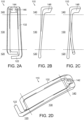
Figures 2A-D illustrate views of a carabiner gate in accordance with embodiments of the present invention; - and
Figures 3A-C illustrate perspective views of a carabiner system in accordance with embodiments of the present invention. - A carabiner system according to claim 1 is provided. It particularly relates to an improved carabiner gate system and method of operation. The carabiner system includes a frame and a gate. The frame includes an opening between a pivot region and a keyed region. The keyed region of the frame may be hookless. The gate is pivotably coupled to the frame across the opening to form a continuously enclosed inner region in the closed configuration. The gate is also pivotably coupled about the pivot region of the frame, forming a gap between the gate and frame in an open configuration. The gate further includes a key-lock region, a gate region, and an attachment region which are integrally formed together without any type of coupling between regions. The gate region includes a plurality of elongated members between the key-lock region and attachment region. The plurality of elongated members may include non-circular cross sections and varying thicknesses and tolerances designed to optimize functionality, weight, and appearance. Also, while embodiments are described in reference to a carabiner gate system, it will be appreciated that the teachings of the present invention are applicable to other areas including but not limited to methods of operation, methods of manufacturing, etc.
- The following terms are defined as follows:
- Integral - A plurality of regions formed together without any type of coupling therebetween. For example, a conventional paperclip has multiple parallel regions without any type of coupling therebetween.
- Molded - a member being formed of a single three-dimensional mold. A molded member may include specific sub-regions having particular shapes and functions. For example, a traditional paperclip is a molded metal structure that does not include any form of couplings between the regions.
- Hookless - a type of carabiner-gate coupling that does not include any type of hook oriented toward the interior of the enclosed carabiner frame.
- Wireless - a structure that is composed of one or more materials that does not include a metal wire.
- Pivotably coupled - two components that are coupled in a manner that enables a pivotal movement therebetween.
- Continuously enclosed region - a two-dimensional region which is enclosed within a substantially continuous structure.
- Reference is initially made to
Figures 1A-C , which illustrate a carabiner system in the closed (Figure 1A ) and open configurations (Figures 1B-C ), designated generally at 100. Thesystem 100 includesframe 150 and agate 110 which are pivotably intercoupled in both open and closed configurations. A continuously enclosedinner region 102 is formed within theframe 150 andgate 110 in the closed configuration (Figure 1A ). The continuously enclosedinner region 102 is a substantially two dimensional region enclosed by a mathematically continuous structure (gate and frame). Agap 104 is formed between a portion of thegate 110 andframe 150 in the open configuration (Figures 1B-C ). Thegap 104 may further be defined as a separation distance between thegate 110 andframe 150. - The
frame 150 is a substantially C-shaped structure with aspine region 170 and anopening 190 between apivot region 160 and akeyed region 180. The frame may be composed of one or more materials, including but not limited to metals and coatings. The frame may include various well known cross sectional shapes so as to optimize weight and strength characteristics, including but not limited to I-beam. It will be appreciated that the various carabiner gate systems discussed in this application may be practiced with a wide variety of carabiner frame structures, styles, and shapes. Thekeyed region 180 may include a flatparallel region 182 and an orthogonal expandedregion 184 as shown inFigure 1C . In preferred embodiments, neither the flat 182 nor expandedregions 184 include any form of hook facing the interior; therefore, thecarabiner system 100 may be referred to as hookless. Rather, the combined shape of the flat and expandedregions gate 110 and theframe 150 creates the necessary operational closed-loop functional strengths in the closed configuration. - Reference is next made to
Figures 2A-D , which illustrate perspective views of the gate, designated generally at 110. Thegate 110 includes anattachment region 120, agate region 130, and a key-lock region 140. Thegate 110 is a critical component which may also be referred to as an integral, molded, and/or single-piece member because there are no couplings, unions, or discontinuities between the defined regions of thegate 110. This unique integral nature of thegate 110 provides numerous functional and manufacturing advantages over conventional multi-component or coupled carabiner gate systems. Theattachment region 120 of thegate 110 is pivotably coupled to thepivot region 160 of theframe 150 via two substantially orthogonalrotating members 122. The orthogonal rotating members may include circular cross-sectional shapes and may extend into corresponding recesses on thepivot region 160 of theframe 150. The specific independent and offset positioning/orientation of the coupling between theattachment region 120 and theframe 150 in part creates the biasing system which urges thegate 110 towards the closed configuration with respect to theframe 150. The urging of thegate 110 towards the closed configuration may also be described as generating a biasing force which corresponds to thegap 104 distance between thegate 110 and theframe 150. The biasing force may also correspond to the composition and shape of thegate 110, which include a metal material shaped to create the malleable compliant spring functionalities. It is important to note that the composition and shape of theentire gate 110 may contribute to the biasing force which urges thegate 110 toward the closed configuration with respect to theframe 150. Thegate region 130 may include twoelongated members 132 as shown in the illustrated embodiments. The elongated members may include non-circular cross-sectional shaped regions and/or discontinuous thickness regions. In particular, theelongated members 132 may include oval, rectangular, and/or other non-circular cross-sectional shapes between theattachment region 120 and the key-lock region 140. Likewise, portions of thegate region 130 may include increased or decreased (discontinuous) thicknesses or densities so as to optimize structural integrity, user operation, and/or biasing. For example, high stress regions may be thicker than low stress areas to facilitate durability and operation. The key-lock region 140 includes a firstsmaller recess 144 and a secondlarger recess 146 corresponding to the keyed region of the frame (SeeFigure 2A ). The firstsmaller recess 144 and secondlarger recess 146 may also be described as defining a partially enclosed three dimensional concave region 142 (SeeFigure 2D ). The illustrated key-lock region 140 includes an externally defined orthogonal substantially rectangular U-shaped region between the elongated members of the gate region (Figures 2B-D ). The external U-shaped region defines the firstsmaller recess 144 corresponding to theflat region 182 of thekeyed region 180 of theframe 150 and the secondlarger recess 146 corresponding to the expandedregion 184 of thekeyed region 180 of theframe 150. - Reference is next made to
Figures 3A-C , which illustrate alternative perspective views of the carabiner system in the closed configuration, designated generally at 100. - In operation, a user may selectively transition the
carabiner system 100 from the biased default closed configuration (Figure 1A ) to the open configuration (Figure 1B-C ) by continuously exerting an opening force 200 (Figures 1B-C ) upon thegate 110 with respect to theframe 150. The openingforce 200 must exceed the biasing force of the biasing system discussed above. In addition, the openingforce 200 must be maintained in order to maintain the open configuration of thecarabiner system 100. Upon removal of the openingforce 200, thegate 110 will pivot about thepivot region 160 of theframe 150 such that the key-lock region 140 couples with thekeyed region 180 of theframe 150, thereby reengaging the closed configuration. The coupling of the key-lock region 140 with thekeyed region 180 may further include coupling the firstsmaller recess 144 over the flatparallel region 182 and coupling the secondlarger recess 146 over the expandedregion 184. Alternatively, the coupling of the key-lock region 140 with thekeyed region 180 may be described as coupling the male keyedregion 180 within the female partiallyenclosed region 142 of thegate 110. - It should be noted that various alternative system designs may be practiced in accordance with the present invention within the scope of the appended claims. Various other embodiments have been contemplated, including combinations in whole or in part of the embodiments described above.
Claims (18)
- A carabiner system (100) comprising:a frame (150) including an opening (190) between a pivot region (160) and a keyed region (180);a gate (110) pivotably coupled to the frame (150) across the opening (190), wherein the gate (110) and frame (150) form a continuously enclosed inner region (102) in a closed configuration, and wherein the gate (110) is pivotably rotated about the pivot region (160) forming a gap (104) between the gate (110) and the frame (150) in the open configuration, and wherein the gate (110) further includes a key-lock region (140), a gate region (130), and an attachment region (120);a gate biasing system between the pivot region (160) of the frame (150) andthe attachment region (120) of the gate (110), wherein the gate biasing system biases the key-lock region (140) of the gate (110) toward the keyed region (180) of the frame (150) in the closed configuration;wherein the closed configuration includes a coupling between the key-lock region (140) of the gate (110) and the keyed region (180) of the frame (150) in the closed configuration;wherein the gate region (130) of the gate (110) includes a plurality of independent elongated members (132) extending between the key-lock region (140) and the attachment region (120);wherein the attachment region (120) is pivotably coupled to the pivot region (160) of the frame (150) in both the open and closed configurations;wherein the key-lock region(140) includes a partially enclosed concave region (142) corresponding in shape to the keyed region (180) of the frame (150);characterized in thatthe key-lock region (140), gate region (130), and attachment region (120) of the gate (110) are integral, wherein the key-lock region (140) of the gate (110) includes an externally defined orthogonal substantially rectangular U-shaped region (148) between the elongated members (132) of the gate region (130).
- The carabiner system of claim 1, wherein the gate (110) is wireless.
- The carabiner system of claim 1, wherein the elongated members (132) include only non-circular cross-sectional regions.
- The carabiner system of claim 1, wherein the regions (120, 130, 140) of the gate (110) are molded.
- The carabiner system of claim 1, wherein the keyed region (180) of the frame (150) is hookless.
- The carabiner system of claim 1, wherein the coupling between the key-lock region (140) and the keyed region (180) in the closed configuration includes a male-female coupling.
- The carabiner system of claim 1, wherein the plurality of elongated members (132) of the gate region (130) include regions of variable thicknesses.
- The carabiner system of claim 1, wherein the external U-shaped region (148) of the key-lock region (140) of the gate (110) includes a first smaller opening (144) and a second larger opening (146), and wherein the first and second openings correspond in shape to the keyed region (180) of the frame.
- The carabiner system of claim 8, wherein the first smaller opening (144) is distal to the gate region (130) of the gate (110) with respect to the second larger opening (146).
- The carabiner system of claim 1, wherein the attachment region (120) of the gate (110) includes two substantially orthogonal regions coupled to the pivot region (160) of the frame (150).
- The carabiner system of claim 10, wherein the two substantially orthogonal regions are substantially orthogonal to the elongated members (132).
- The carabiner system of claim 11, wherein the pivotable coupling between the attachment region (120) and the pivot region (160) includes coupling the substantially orthogonal regions of the gate (110) within a plurality of recesses of the frame.
- The carabiner system of claim 12, wherein the plurality of recesses are offset and disposed on the attachment region (120) of the frame (150).
- The carabiner system of claim 1, wherein the gate (110) is substantially composed of a single material.
- The carabiner system of claim 1, wherein the attachment region (120), the gate region (130), and key-lock region (140) of the gate (110) are inter-molded without compression coupling.
- The carabiner system of claim 1, wherein the gate biasing system is configured to generate a biasing force urging the gate (110) toward the closed configuration.
- The carabiner system of claim 16, wherein the biasing force corresponds to a distance between the key-lock region (140) of the gate (110) and the keyed region (180) of the frame (150).
- The carabiner system of claim 1, wherein the key-lock region (140) is hookless, wherein the key-lock region, the gate region and attachment region of the gate are molded.
Applications Claiming Priority (2)
| Application Number | Priority Date | Filing Date | Title |
|---|---|---|---|
| US201762500515P | 2017-05-03 | 2017-05-03 | |
| US15/917,922 US20180320729A1 (en) | 2017-05-03 | 2018-03-12 | Carabiner systems and methods |
Publications (2)
| Publication Number | Publication Date |
|---|---|
| EP3399201A1 EP3399201A1 (en) | 2018-11-07 |
| EP3399201B1 true EP3399201B1 (en) | 2024-08-28 |
Family
ID=62089598
Family Applications (1)
| Application Number | Title | Priority Date | Filing Date |
|---|---|---|---|
| EP18169755.8A Active EP3399201B1 (en) | 2017-05-03 | 2018-04-27 | Improved carabiner system |
Country Status (2)
| Country | Link |
|---|---|
| US (1) | US20180320729A1 (en) |
| EP (1) | EP3399201B1 (en) |
Families Citing this family (4)
| Publication number | Priority date | Publication date | Assignee | Title |
|---|---|---|---|---|
| US11286973B1 (en) | 2020-12-22 | 2022-03-29 | Black Diamond Equipment, Ltd. | Systems and methods for carabiner gate automatic locking |
| US20230235776A1 (en) * | 2022-01-26 | 2023-07-27 | Peter Grossman | Systems and methods for a locking carabiner |
| USD1056700S1 (en) * | 2022-12-14 | 2025-01-07 | Bison Designs, Llc | Fish shaped carabiner |
| EP4450837B1 (en) | 2023-04-17 | 2026-02-25 | Teufelberger Fiber Rope GmbH | Tool carabiner for securing tools to a strap |
Citations (1)
| Publication number | Priority date | Publication date | Assignee | Title |
|---|---|---|---|---|
| IT100813S (en) * | 2012-04-13 | 2014-01-23 |
Family Cites Families (6)
| Publication number | Priority date | Publication date | Assignee | Title |
|---|---|---|---|---|
| US5878834A (en) * | 1996-01-16 | 1999-03-09 | Black Diamond Equipment, Ltd | Formed sheet metal carabiner gate |
| JP3705961B2 (en) * | 1999-07-09 | 2005-10-12 | 株式会社伊藤製作所 | Connecting ring |
| FR2807329B1 (en) * | 2000-04-07 | 2002-06-28 | Zedel | SAFETY CARABINER |
| US20090000086A1 (en) * | 2007-06-28 | 2009-01-01 | Liang Bing | Hook |
| ITMI20131543A1 (en) * | 2013-09-19 | 2015-03-20 | Camp Spa | SNAP HOOK WITH CLIMBING LEVER |
| US9797432B2 (en) * | 2015-05-22 | 2017-10-24 | Thanasit Inkavesvaanit | Systems and methods for providing a quick-release carabiner |
-
2018
- 2018-03-12 US US15/917,922 patent/US20180320729A1/en not_active Abandoned
- 2018-04-27 EP EP18169755.8A patent/EP3399201B1/en active Active
Patent Citations (1)
| Publication number | Priority date | Publication date | Assignee | Title |
|---|---|---|---|---|
| IT100813S (en) * | 2012-04-13 | 2014-01-23 |
Also Published As
| Publication number | Publication date |
|---|---|
| EP3399201A1 (en) | 2018-11-07 |
| US20180320729A1 (en) | 2018-11-08 |
Similar Documents
| Publication | Publication Date | Title |
|---|---|---|
| EP2341255B1 (en) | Improved wire-gate carabiner | |
| EP3399201A1 (en) | Improved carabiner system | |
| EP2527670B1 (en) | Magnetic carabiner system | |
| US9657807B2 (en) | System for elastically averaging assembly of components | |
| EP2812259B1 (en) | Spaced multi-rib zipper | |
| US9446722B2 (en) | Elastic averaging alignment member | |
| US9067625B2 (en) | Elastic retaining arrangement for jointed components and method of reducing a gap between jointed components | |
| US9382935B2 (en) | Elastic tubular attachment assembly for mating components and method of mating components | |
| US10104943B2 (en) | Pull and release latch | |
| EP2753836B1 (en) | Lockable snap-clip fastener | |
| US20140366326A1 (en) | Elastically deformable retaining hook for components to be mated together and method of assembling | |
| US9481317B2 (en) | Elastically deformable clip and method | |
| US8904599B2 (en) | Quick coupling furniture hinge | |
| US20150098748A1 (en) | Elastically averaged alignment systems and methods | |
| CN103511410B (en) | Fastener and manufacturing method thereof | |
| US20140373320A1 (en) | Safety carabiner comprising a double gate | |
| EP3396298A1 (en) | Rapid release device for wearable articles | |
| US9428046B2 (en) | Alignment and retention system for laterally slideably engageable mating components | |
| US20190111558A1 (en) | Combination Tool Attachment System | |
| US10334911B2 (en) | Buckle | |
| EP2255900A1 (en) | Sheet of material with joint | |
| EP2851572B1 (en) | Carabiner with wire lever for climbing | |
| US720378A (en) | Swivel snap-hook. | |
| CN201277244Y (en) | Inserted hook | |
| CN105298109A (en) | Fastener |
Legal Events
| Date | Code | Title | Description |
|---|---|---|---|
| PUAI | Public reference made under article 153(3) epc to a published international application that has entered the european phase |
Free format text: ORIGINAL CODE: 0009012 |
|
| STAA | Information on the status of an ep patent application or granted ep patent |
Free format text: STATUS: THE APPLICATION HAS BEEN PUBLISHED |
|
| AK | Designated contracting states |
Kind code of ref document: A1 Designated state(s): AL AT BE BG CH CY CZ DE DK EE ES FI FR GB GR HR HU IE IS IT LI LT LU LV MC MK MT NL NO PL PT RO RS SE SI SK SM TR |
|
| AX | Request for extension of the european patent |
Extension state: BA ME |
|
| STAA | Information on the status of an ep patent application or granted ep patent |
Free format text: STATUS: REQUEST FOR EXAMINATION WAS MADE |
|
| 17P | Request for examination filed |
Effective date: 20190507 |
|
| RBV | Designated contracting states (corrected) |
Designated state(s): AL AT BE BG CH CY CZ DE DK EE ES FI FR GB GR HR HU IE IS IT LI LT LU LV MC MK MT NL NO PL PT RO RS SE SI SK SM TR |
|
| STAA | Information on the status of an ep patent application or granted ep patent |
Free format text: STATUS: EXAMINATION IS IN PROGRESS |
|
| 17Q | First examination report despatched |
Effective date: 20210517 |
|
| GRAP | Despatch of communication of intention to grant a patent |
Free format text: ORIGINAL CODE: EPIDOSNIGR1 |
|
| STAA | Information on the status of an ep patent application or granted ep patent |
Free format text: STATUS: GRANT OF PATENT IS INTENDED |
|
| INTG | Intention to grant announced |
Effective date: 20211220 |
|
| TPAC | Observations filed by third parties |
Free format text: ORIGINAL CODE: EPIDOSNTIPA |
|
| GRAJ | Information related to disapproval of communication of intention to grant by the applicant or resumption of examination proceedings by the epo deleted |
Free format text: ORIGINAL CODE: EPIDOSDIGR1 |
|
| STAA | Information on the status of an ep patent application or granted ep patent |
Free format text: STATUS: EXAMINATION IS IN PROGRESS |
|
| INTC | Intention to grant announced (deleted) | ||
| R17C | First examination report despatched (corrected) |
Effective date: 20210517 |
|
| P01 | Opt-out of the competence of the unified patent court (upc) registered |
Effective date: 20230530 |
|
| GRAP | Despatch of communication of intention to grant a patent |
Free format text: ORIGINAL CODE: EPIDOSNIGR1 |
|
| STAA | Information on the status of an ep patent application or granted ep patent |
Free format text: STATUS: GRANT OF PATENT IS INTENDED |
|
| INTG | Intention to grant announced |
Effective date: 20240327 |
|
| GRAS | Grant fee paid |
Free format text: ORIGINAL CODE: EPIDOSNIGR3 |
|
| GRAA | (expected) grant |
Free format text: ORIGINAL CODE: 0009210 |
|
| STAA | Information on the status of an ep patent application or granted ep patent |
Free format text: STATUS: THE PATENT HAS BEEN GRANTED |
|
| AK | Designated contracting states |
Kind code of ref document: B1 Designated state(s): AL AT BE BG CH CY CZ DE DK EE ES FI FR GB GR HR HU IE IS IT LI LT LU LV MC MK MT NL NO PL PT RO RS SE SI SK SM TR |
|
| REG | Reference to a national code |
Ref country code: GB Ref legal event code: FG4D |
|
| REG | Reference to a national code |
Ref country code: CH Ref legal event code: EP |
|
| REG | Reference to a national code |
Ref country code: DE Ref legal event code: R096 Ref document number: 602018073552 Country of ref document: DE |
|
| REG | Reference to a national code |
Ref country code: IE Ref legal event code: FG4D |
|
| REG | Reference to a national code |
Ref country code: LT Ref legal event code: MG9D |
|
| PG25 | Lapsed in a contracting state [announced via postgrant information from national office to epo] |
Ref country code: NO Free format text: LAPSE BECAUSE OF FAILURE TO SUBMIT A TRANSLATION OF THE DESCRIPTION OR TO PAY THE FEE WITHIN THE PRESCRIBED TIME-LIMIT Effective date: 20241128 |
|
| REG | Reference to a national code |
Ref country code: AT Ref legal event code: MK05 Ref document number: 1718234 Country of ref document: AT Kind code of ref document: T Effective date: 20240828 |
|
| PG25 | Lapsed in a contracting state [announced via postgrant information from national office to epo] |
Ref country code: NL Free format text: LAPSE BECAUSE OF FAILURE TO SUBMIT A TRANSLATION OF THE DESCRIPTION OR TO PAY THE FEE WITHIN THE PRESCRIBED TIME-LIMIT Effective date: 20240828 Ref country code: FI Free format text: LAPSE BECAUSE OF FAILURE TO SUBMIT A TRANSLATION OF THE DESCRIPTION OR TO PAY THE FEE WITHIN THE PRESCRIBED TIME-LIMIT Effective date: 20240828 Ref country code: PT Free format text: LAPSE BECAUSE OF FAILURE TO SUBMIT A TRANSLATION OF THE DESCRIPTION OR TO PAY THE FEE WITHIN THE PRESCRIBED TIME-LIMIT Effective date: 20241230 Ref country code: GR Free format text: LAPSE BECAUSE OF FAILURE TO SUBMIT A TRANSLATION OF THE DESCRIPTION OR TO PAY THE FEE WITHIN THE PRESCRIBED TIME-LIMIT Effective date: 20241129 Ref country code: PL Free format text: LAPSE BECAUSE OF FAILURE TO SUBMIT A TRANSLATION OF THE DESCRIPTION OR TO PAY THE FEE WITHIN THE PRESCRIBED TIME-LIMIT Effective date: 20240828 |
|
| PG25 | Lapsed in a contracting state [announced via postgrant information from national office to epo] |
Ref country code: BG Free format text: LAPSE BECAUSE OF FAILURE TO SUBMIT A TRANSLATION OF THE DESCRIPTION OR TO PAY THE FEE WITHIN THE PRESCRIBED TIME-LIMIT Effective date: 20240828 |
|
| PG25 | Lapsed in a contracting state [announced via postgrant information from national office to epo] |
Ref country code: LV Free format text: LAPSE BECAUSE OF FAILURE TO SUBMIT A TRANSLATION OF THE DESCRIPTION OR TO PAY THE FEE WITHIN THE PRESCRIBED TIME-LIMIT Effective date: 20240828 |
|
| REG | Reference to a national code |
Ref country code: NL Ref legal event code: MP Effective date: 20240828 |
|
| PG25 | Lapsed in a contracting state [announced via postgrant information from national office to epo] |
Ref country code: IS Free format text: LAPSE BECAUSE OF FAILURE TO SUBMIT A TRANSLATION OF THE DESCRIPTION OR TO PAY THE FEE WITHIN THE PRESCRIBED TIME-LIMIT Effective date: 20241228 Ref country code: AT Free format text: LAPSE BECAUSE OF FAILURE TO SUBMIT A TRANSLATION OF THE DESCRIPTION OR TO PAY THE FEE WITHIN THE PRESCRIBED TIME-LIMIT Effective date: 20240828 |
|
| PG25 | Lapsed in a contracting state [announced via postgrant information from national office to epo] |
Ref country code: HR Free format text: LAPSE BECAUSE OF FAILURE TO SUBMIT A TRANSLATION OF THE DESCRIPTION OR TO PAY THE FEE WITHIN THE PRESCRIBED TIME-LIMIT Effective date: 20240828 |
|
| PG25 | Lapsed in a contracting state [announced via postgrant information from national office to epo] |
Ref country code: ES Free format text: LAPSE BECAUSE OF FAILURE TO SUBMIT A TRANSLATION OF THE DESCRIPTION OR TO PAY THE FEE WITHIN THE PRESCRIBED TIME-LIMIT Effective date: 20240828 Ref country code: RS Free format text: LAPSE BECAUSE OF FAILURE TO SUBMIT A TRANSLATION OF THE DESCRIPTION OR TO PAY THE FEE WITHIN THE PRESCRIBED TIME-LIMIT Effective date: 20241128 |
|
| PG25 | Lapsed in a contracting state [announced via postgrant information from national office to epo] |
Ref country code: RS Free format text: LAPSE BECAUSE OF FAILURE TO SUBMIT A TRANSLATION OF THE DESCRIPTION OR TO PAY THE FEE WITHIN THE PRESCRIBED TIME-LIMIT Effective date: 20241128 Ref country code: PT Free format text: LAPSE BECAUSE OF FAILURE TO SUBMIT A TRANSLATION OF THE DESCRIPTION OR TO PAY THE FEE WITHIN THE PRESCRIBED TIME-LIMIT Effective date: 20241230 Ref country code: PL Free format text: LAPSE BECAUSE OF FAILURE TO SUBMIT A TRANSLATION OF THE DESCRIPTION OR TO PAY THE FEE WITHIN THE PRESCRIBED TIME-LIMIT Effective date: 20240828 Ref country code: NO Free format text: LAPSE BECAUSE OF FAILURE TO SUBMIT A TRANSLATION OF THE DESCRIPTION OR TO PAY THE FEE WITHIN THE PRESCRIBED TIME-LIMIT Effective date: 20241128 Ref country code: NL Free format text: LAPSE BECAUSE OF FAILURE TO SUBMIT A TRANSLATION OF THE DESCRIPTION OR TO PAY THE FEE WITHIN THE PRESCRIBED TIME-LIMIT Effective date: 20240828 Ref country code: LV Free format text: LAPSE BECAUSE OF FAILURE TO SUBMIT A TRANSLATION OF THE DESCRIPTION OR TO PAY THE FEE WITHIN THE PRESCRIBED TIME-LIMIT Effective date: 20240828 Ref country code: IS Free format text: LAPSE BECAUSE OF FAILURE TO SUBMIT A TRANSLATION OF THE DESCRIPTION OR TO PAY THE FEE WITHIN THE PRESCRIBED TIME-LIMIT Effective date: 20241228 Ref country code: HR Free format text: LAPSE BECAUSE OF FAILURE TO SUBMIT A TRANSLATION OF THE DESCRIPTION OR TO PAY THE FEE WITHIN THE PRESCRIBED TIME-LIMIT Effective date: 20240828 Ref country code: GR Free format text: LAPSE BECAUSE OF FAILURE TO SUBMIT A TRANSLATION OF THE DESCRIPTION OR TO PAY THE FEE WITHIN THE PRESCRIBED TIME-LIMIT Effective date: 20241129 Ref country code: FI Free format text: LAPSE BECAUSE OF FAILURE TO SUBMIT A TRANSLATION OF THE DESCRIPTION OR TO PAY THE FEE WITHIN THE PRESCRIBED TIME-LIMIT Effective date: 20240828 Ref country code: ES Free format text: LAPSE BECAUSE OF FAILURE TO SUBMIT A TRANSLATION OF THE DESCRIPTION OR TO PAY THE FEE WITHIN THE PRESCRIBED TIME-LIMIT Effective date: 20240828 Ref country code: BG Free format text: LAPSE BECAUSE OF FAILURE TO SUBMIT A TRANSLATION OF THE DESCRIPTION OR TO PAY THE FEE WITHIN THE PRESCRIBED TIME-LIMIT Effective date: 20240828 Ref country code: AT Free format text: LAPSE BECAUSE OF FAILURE TO SUBMIT A TRANSLATION OF THE DESCRIPTION OR TO PAY THE FEE WITHIN THE PRESCRIBED TIME-LIMIT Effective date: 20240828 |
|
| PG25 | Lapsed in a contracting state [announced via postgrant information from national office to epo] |
Ref country code: SM Free format text: LAPSE BECAUSE OF FAILURE TO SUBMIT A TRANSLATION OF THE DESCRIPTION OR TO PAY THE FEE WITHIN THE PRESCRIBED TIME-LIMIT Effective date: 20240828 Ref country code: DK Free format text: LAPSE BECAUSE OF FAILURE TO SUBMIT A TRANSLATION OF THE DESCRIPTION OR TO PAY THE FEE WITHIN THE PRESCRIBED TIME-LIMIT Effective date: 20240828 Ref country code: RO Free format text: LAPSE BECAUSE OF FAILURE TO SUBMIT A TRANSLATION OF THE DESCRIPTION OR TO PAY THE FEE WITHIN THE PRESCRIBED TIME-LIMIT Effective date: 20240828 |
|
| PG25 | Lapsed in a contracting state [announced via postgrant information from national office to epo] |
Ref country code: EE Free format text: LAPSE BECAUSE OF FAILURE TO SUBMIT A TRANSLATION OF THE DESCRIPTION OR TO PAY THE FEE WITHIN THE PRESCRIBED TIME-LIMIT Effective date: 20240828 |
|
| PG25 | Lapsed in a contracting state [announced via postgrant information from national office to epo] |
Ref country code: CZ Free format text: LAPSE BECAUSE OF FAILURE TO SUBMIT A TRANSLATION OF THE DESCRIPTION OR TO PAY THE FEE WITHIN THE PRESCRIBED TIME-LIMIT Effective date: 20240828 |
|
| PG25 | Lapsed in a contracting state [announced via postgrant information from national office to epo] |
Ref country code: SK Free format text: LAPSE BECAUSE OF FAILURE TO SUBMIT A TRANSLATION OF THE DESCRIPTION OR TO PAY THE FEE WITHIN THE PRESCRIBED TIME-LIMIT Effective date: 20240828 |
|
| REG | Reference to a national code |
Ref country code: DE Ref legal event code: R097 Ref document number: 602018073552 Country of ref document: DE |
|
| PLBE | No opposition filed within time limit |
Free format text: ORIGINAL CODE: 0009261 |
|
| STAA | Information on the status of an ep patent application or granted ep patent |
Free format text: STATUS: NO OPPOSITION FILED WITHIN TIME LIMIT |
|
| PGFP | Annual fee paid to national office [announced via postgrant information from national office to epo] |
Ref country code: DE Payment date: 20250422 Year of fee payment: 8 |
|
| PGFP | Annual fee paid to national office [announced via postgrant information from national office to epo] |
Ref country code: IT Payment date: 20250424 Year of fee payment: 8 |
|
| PGFP | Annual fee paid to national office [announced via postgrant information from national office to epo] |
Ref country code: FR Payment date: 20250425 Year of fee payment: 8 |
|
| 26N | No opposition filed |
Effective date: 20250530 |
|
| PG25 | Lapsed in a contracting state [announced via postgrant information from national office to epo] |
Ref country code: SE Free format text: LAPSE BECAUSE OF FAILURE TO SUBMIT A TRANSLATION OF THE DESCRIPTION OR TO PAY THE FEE WITHIN THE PRESCRIBED TIME-LIMIT Effective date: 20240828 |
|
| REG | Reference to a national code |
Ref country code: CH Ref legal event code: H13 Free format text: ST27 STATUS EVENT CODE: U-0-0-H10-H13 (AS PROVIDED BY THE NATIONAL OFFICE) Effective date: 20251125 |
|
| PG25 | Lapsed in a contracting state [announced via postgrant information from national office to epo] |
Ref country code: LU Free format text: LAPSE BECAUSE OF NON-PAYMENT OF DUE FEES Effective date: 20250427 |
|
| PG25 | Lapsed in a contracting state [announced via postgrant information from national office to epo] |
Ref country code: MC Free format text: LAPSE BECAUSE OF FAILURE TO SUBMIT A TRANSLATION OF THE DESCRIPTION OR TO PAY THE FEE WITHIN THE PRESCRIBED TIME-LIMIT Effective date: 20240828 |
|
| GBPC | Gb: european patent ceased through non-payment of renewal fee |
Effective date: 20250427 |
|
| REG | Reference to a national code |
Ref country code: BE Ref legal event code: MM Effective date: 20250430 |
|
| PG25 | Lapsed in a contracting state [announced via postgrant information from national office to epo] |
Ref country code: GB Free format text: LAPSE BECAUSE OF NON-PAYMENT OF DUE FEES Effective date: 20250427 |
|
| PG25 | Lapsed in a contracting state [announced via postgrant information from national office to epo] |
Ref country code: BE Free format text: LAPSE BECAUSE OF NON-PAYMENT OF DUE FEES Effective date: 20250430 |
|
| PG25 | Lapsed in a contracting state [announced via postgrant information from national office to epo] |
Ref country code: CH Free format text: LAPSE BECAUSE OF NON-PAYMENT OF DUE FEES Effective date: 20250430 |
|
| PG25 | Lapsed in a contracting state [announced via postgrant information from national office to epo] |
Ref country code: IE Free format text: LAPSE BECAUSE OF NON-PAYMENT OF DUE FEES Effective date: 20250427 |