EP3399182A1 - Geräuscharme rotorblattspitze - Google Patents
Geräuscharme rotorblattspitze Download PDFInfo
- Publication number
- EP3399182A1 EP3399182A1 EP17169755.0A EP17169755A EP3399182A1 EP 3399182 A1 EP3399182 A1 EP 3399182A1 EP 17169755 A EP17169755 A EP 17169755A EP 3399182 A1 EP3399182 A1 EP 3399182A1
- Authority
- EP
- European Patent Office
- Prior art keywords
- rotor blade
- blade tip
- surface portion
- rough surface
- elevations
- Prior art date
- Legal status (The legal status is an assumption and is not a legal conclusion. Google has not performed a legal analysis and makes no representation as to the accuracy of the status listed.)
- Granted
Links
Images

Classifications
-
- F—MECHANICAL ENGINEERING; LIGHTING; HEATING; WEAPONS; BLASTING
- F03—MACHINES OR ENGINES FOR LIQUIDS; WIND, SPRING, OR WEIGHT MOTORS; PRODUCING MECHANICAL POWER OR A REACTIVE PROPULSIVE THRUST, NOT OTHERWISE PROVIDED FOR
- F03D—WIND MOTORS
- F03D1/00—Wind motors with rotation axis substantially parallel to the air flow entering the rotor
- F03D1/06—Rotors
- F03D1/0608—Rotors characterised by their aerodynamic shape
- F03D1/0633—Rotors characterised by their aerodynamic shape of the blades
-
- F—MECHANICAL ENGINEERING; LIGHTING; HEATING; WEAPONS; BLASTING
- F03—MACHINES OR ENGINES FOR LIQUIDS; WIND, SPRING, OR WEIGHT MOTORS; PRODUCING MECHANICAL POWER OR A REACTIVE PROPULSIVE THRUST, NOT OTHERWISE PROVIDED FOR
- F03D—WIND MOTORS
- F03D1/00—Wind motors with rotation axis substantially parallel to the air flow entering the rotor
- F03D1/06—Rotors
- F03D1/065—Rotors characterised by their construction elements
- F03D1/0675—Rotors characterised by their construction elements of the blades
-
- F—MECHANICAL ENGINEERING; LIGHTING; HEATING; WEAPONS; BLASTING
- F05—INDEXING SCHEMES RELATING TO ENGINES OR PUMPS IN VARIOUS SUBCLASSES OF CLASSES F01-F04
- F05B—INDEXING SCHEME RELATING TO WIND, SPRING, WEIGHT, INERTIA OR LIKE MOTORS, TO MACHINES OR ENGINES FOR LIQUIDS COVERED BY SUBCLASSES F03B, F03D AND F03G
- F05B2230/00—Manufacture
- F05B2230/20—Manufacture essentially without removing material
- F05B2230/21—Manufacture essentially without removing material by casting
-
- F—MECHANICAL ENGINEERING; LIGHTING; HEATING; WEAPONS; BLASTING
- F05—INDEXING SCHEMES RELATING TO ENGINES OR PUMPS IN VARIOUS SUBCLASSES OF CLASSES F01-F04
- F05B—INDEXING SCHEME RELATING TO WIND, SPRING, WEIGHT, INERTIA OR LIKE MOTORS, TO MACHINES OR ENGINES FOR LIQUIDS COVERED BY SUBCLASSES F03B, F03D AND F03G
- F05B2230/00—Manufacture
- F05B2230/80—Repairing, retrofitting or upgrading methods
-
- F—MECHANICAL ENGINEERING; LIGHTING; HEATING; WEAPONS; BLASTING
- F05—INDEXING SCHEMES RELATING TO ENGINES OR PUMPS IN VARIOUS SUBCLASSES OF CLASSES F01-F04
- F05B—INDEXING SCHEME RELATING TO WIND, SPRING, WEIGHT, INERTIA OR LIKE MOTORS, TO MACHINES OR ENGINES FOR LIQUIDS COVERED BY SUBCLASSES F03B, F03D AND F03G
- F05B2240/00—Components
- F05B2240/20—Rotors
- F05B2240/30—Characteristics of rotor blades, i.e. of any element transforming dynamic fluid energy to or from rotational energy and being attached to a rotor
- F05B2240/32—Characteristics of rotor blades, i.e. of any element transforming dynamic fluid energy to or from rotational energy and being attached to a rotor with roughened surface
-
- F—MECHANICAL ENGINEERING; LIGHTING; HEATING; WEAPONS; BLASTING
- F05—INDEXING SCHEMES RELATING TO ENGINES OR PUMPS IN VARIOUS SUBCLASSES OF CLASSES F01-F04
- F05B—INDEXING SCHEME RELATING TO WIND, SPRING, WEIGHT, INERTIA OR LIKE MOTORS, TO MACHINES OR ENGINES FOR LIQUIDS COVERED BY SUBCLASSES F03B, F03D AND F03G
- F05B2250/00—Geometry
- F05B2250/10—Geometry two-dimensional
- F05B2250/18—Geometry two-dimensional patterned
-
- F—MECHANICAL ENGINEERING; LIGHTING; HEATING; WEAPONS; BLASTING
- F05—INDEXING SCHEMES RELATING TO ENGINES OR PUMPS IN VARIOUS SUBCLASSES OF CLASSES F01-F04
- F05B—INDEXING SCHEME RELATING TO WIND, SPRING, WEIGHT, INERTIA OR LIKE MOTORS, TO MACHINES OR ENGINES FOR LIQUIDS COVERED BY SUBCLASSES F03B, F03D AND F03G
- F05B2250/00—Geometry
- F05B2250/10—Geometry two-dimensional
- F05B2250/18—Geometry two-dimensional patterned
- F05B2250/183—Geometry two-dimensional patterned zigzag
-
- F—MECHANICAL ENGINEERING; LIGHTING; HEATING; WEAPONS; BLASTING
- F05—INDEXING SCHEMES RELATING TO ENGINES OR PUMPS IN VARIOUS SUBCLASSES OF CLASSES F01-F04
- F05B—INDEXING SCHEME RELATING TO WIND, SPRING, WEIGHT, INERTIA OR LIKE MOTORS, TO MACHINES OR ENGINES FOR LIQUIDS COVERED BY SUBCLASSES F03B, F03D AND F03G
- F05B2260/00—Function
- F05B2260/96—Preventing, counteracting or reducing vibration or noise
- F05B2260/962—Preventing, counteracting or reducing vibration or noise by means creating "anti-noise"
-
- F—MECHANICAL ENGINEERING; LIGHTING; HEATING; WEAPONS; BLASTING
- F05—INDEXING SCHEMES RELATING TO ENGINES OR PUMPS IN VARIOUS SUBCLASSES OF CLASSES F01-F04
- F05B—INDEXING SCHEME RELATING TO WIND, SPRING, WEIGHT, INERTIA OR LIKE MOTORS, TO MACHINES OR ENGINES FOR LIQUIDS COVERED BY SUBCLASSES F03B, F03D AND F03G
- F05B2280/00—Materials; Properties thereof
- F05B2280/10—Inorganic materials, e.g. metals
-
- F—MECHANICAL ENGINEERING; LIGHTING; HEATING; WEAPONS; BLASTING
- F05—INDEXING SCHEMES RELATING TO ENGINES OR PUMPS IN VARIOUS SUBCLASSES OF CLASSES F01-F04
- F05B—INDEXING SCHEME RELATING TO WIND, SPRING, WEIGHT, INERTIA OR LIKE MOTORS, TO MACHINES OR ENGINES FOR LIQUIDS COVERED BY SUBCLASSES F03B, F03D AND F03G
- F05B2280/00—Materials; Properties thereof
- F05B2280/10—Inorganic materials, e.g. metals
- F05B2280/102—Light metals
- F05B2280/1021—Aluminium
-
- Y—GENERAL TAGGING OF NEW TECHNOLOGICAL DEVELOPMENTS; GENERAL TAGGING OF CROSS-SECTIONAL TECHNOLOGIES SPANNING OVER SEVERAL SECTIONS OF THE IPC; TECHNICAL SUBJECTS COVERED BY FORMER USPC CROSS-REFERENCE ART COLLECTIONS [XRACs] AND DIGESTS
- Y02—TECHNOLOGIES OR APPLICATIONS FOR MITIGATION OR ADAPTATION AGAINST CLIMATE CHANGE
- Y02E—REDUCTION OF GREENHOUSE GAS [GHG] EMISSIONS, RELATED TO ENERGY GENERATION, TRANSMISSION OR DISTRIBUTION
- Y02E10/00—Energy generation through renewable energy sources
- Y02E10/70—Wind energy
- Y02E10/72—Wind turbines with rotation axis in wind direction
-
- Y—GENERAL TAGGING OF NEW TECHNOLOGICAL DEVELOPMENTS; GENERAL TAGGING OF CROSS-SECTIONAL TECHNOLOGIES SPANNING OVER SEVERAL SECTIONS OF THE IPC; TECHNICAL SUBJECTS COVERED BY FORMER USPC CROSS-REFERENCE ART COLLECTIONS [XRACs] AND DIGESTS
- Y02—TECHNOLOGIES OR APPLICATIONS FOR MITIGATION OR ADAPTATION AGAINST CLIMATE CHANGE
- Y02P—CLIMATE CHANGE MITIGATION TECHNOLOGIES IN THE PRODUCTION OR PROCESSING OF GOODS
- Y02P70/00—Climate change mitigation technologies in the production process for final industrial or consumer products
- Y02P70/50—Manufacturing or production processes characterised by the final manufactured product
Definitions
- the invention relates to a rotor blade tip for a wind turbine rotor blade and a wind turbine rotor blade with such a rotor blade tip.
- Aerodynamic investigations on wind turbine rotor blades have shown that the aerodynamic efficiency can be reduced, especially in the region of the rotor blade tip.
- the reason for this is usually a low Reynolds number at the rotor blade tip, which leads to a detachment of the laminar air flow from the rotor blade surface and to the formation of unstable eddy currents.
- peeling bubbles form near the profile nose edge of the rotor blade.
- the laminar air flow is detached over a large area of the rotor blade surface, resulting in lower energy efficiency.
- Such stalls and the associated turbulence are the main cause of unwanted noise during operation of a wind turbine.
- the laminar air flow running directly on the rotor blade surface can be deliberately converted into a turbulent air flow before detachment bubbles can form.
- a turbulent air flow introduces more energy into the boundary layer surrounding the rotor blade and creates a more stable laminar air flow above the (micro) turbulence.
- indentations in the surface of rotor blade shells or provided with indentations films subsequently applied to the rotor blade shells Rotor blade shells with such unevenness, for example, in EP 1 469 198 A1 .
- WO 2012/02889081 such as DE 10 2006 054 683 A1 described.
- the invention has for its object to provide a rotor blade tip for a wind turbine rotor blade available that is easy to manufacture and resistant and avoids annoying noise.
- a rotor blade tip for a wind turbine rotor blade the rotor blade tip being made of metal and a surface of the rotor blade tip formed by the metal having a rough surface portion.
- a rotor blade tip is made of metal, in particular of aluminum.
- the rotor blade tip can be designed for connection to the blade shell of a wind turbine rotor blade, for example for bonding to the blade shell.
- the metal rotor blade tip can serve as a lightning receptor.
- the rotor blade tip can continue the aerodynamic profile of the leaf shell.
- a rough surface section extends over at least part of the surface of the metal rotor blade tip.
- the metal surface of the rotor blade tip thus has a roughness. As roughness this unevenness in the surface of the rotor blade tip are understood.
- the rough surface portion may be uneven, in particular with respect to the surface portions of the rotor blade tip surrounding it.
- the rough surface portion Due to the rough surface portion, a flow separation of the air flow flowing along the surface of the rotor blade tip can be avoided.
- the rough surface section generates targeted slight turbulence in the laminar air flow.
- the air flow adheres to the surface of the rotor blade tip, wherein the flow running above a generated turbulent boundary layer remains substantially laminar.
- the rough surface portion in the metal rotor blade tip thus eliminates the major source of noise in the operation of wind turbines. The inventors have realized that it is sufficient for this, only one rotor blade tip To provide a rough surface in sections, rather than a complete rotor blade to prepare such.
- the rotor blade tip according to the invention is easier to manufacture than the recesses known from the prior art in rotor blade shells usually made of fiber composite materials.
- the rough surface section is more resistant to the weather, such as against wind, rain or sunlight. Even after several lightning strikes, the metallic rotor blade tip can retain its roughness and thus its aerodynamic properties. This is particularly advantageous over the known from the prior art, adhered to the blade shell of a rotor blade films advantageous because they are particularly affected by the weather. Thus, it often comes to the replacement of the films, which not only prevents the targeted generation of turbulence, but also affects the aerodynamic properties of the rotor blade and is accompanied by an undesirable noise.
- the rough surface portion of the rotor blade tip is formed by a plurality of depressions and / or elevations introduced into the surface of the rotor blade tip.
- the unevenness of the rough surface portion may therefore be formed by depressions, elevations or by a combination of depressions and elevations introduced into the surface of the rotor blade tip.
- the depressions and / or elevations may already be formed integrally therewith during the production of the metal rotor blade tip.
- the depressions and / or elevations can be subsequently introduced into the surface of the metal rotor blade tip, for example in a cutting process or another shaping process.
- the roughness of the surface can be defined in particular as a mean distance of the depressions and / or elevations from a reference plane.
- the reference plane may, for example, follow the aerodynamic profile of the rotor blade tip, in particular the surface of the metal rotor blade tip surrounding the rough surface portion.
- the reference plane may, in particular, be an imaginary center plane which intersects a contour formed by the elevations / depressions in such a way that the sum of the deviations of the contour from the center plane caused by the elevations / depressions becomes minimal.
- the recesses extend between 0.1 mm and 1 mm into the surface of the rotor blade tip. Also, the elevations between 0.1 mm and 1 mm may extend out of the surface of the rotor blade tip. Such minor bumps are already sufficient to produce the desired turbulence and to avoid a stall.
- the depressions and / or elevations are formed lens or hemispherical or cuboid.
- the depressions may extend into the surface of the rotor blade tip in a hemispherical manner or the protrusions may extend out of the surface in a hemispherical manner. The same applies to the lens or cuboid unevenness.
- the depressions and / or elevations are arranged in a zig-zag shape.
- the rough surface portion may thus extend along a zig-zag line.
- the rough surface portion is arranged in strip form at a uniform distance from a profile nose card.
- the length of the strip-shaped surface portion may be, for example, in the range of 10 cm to 100 cm.
- the rough surface portion may extend in particular along the entire length of the metallic rotor blade tip.
- the rough surface portion is strip-shaped because its extent is greater along the length of the rotor blade tip than along the chord perpendicular to the length.
- the strip-shaped surface portion may have a width in the direction have chord in the range of 1 cm to 3 cm.
- a strip-shaped rough surface portion is already sufficient to avoid a stall and thus disturbing noise. Such a strip-shaped surface portion is particularly efficient and can be produced with little effort.
- the arrangement of the rough surface portion at a uniform distance from the profile nose edge means the arrangement on the same chord position.
- the distance from the profile nose edge can be in the range of 0% to 50% of the length of the chord, with the profile nose edge being at 0% length of the chord.
- an arrangement of the rough surface portion is dependent on which position usually a flow separation would occur. This is particularly dependent on the profile profile of the rotor blade tip and its angle of attack relative to the wind. In most cases, flow separation occurs in the stated range from 0% to 50% of the length of the chord.
- the rotor blade tip has a projection extending along a profile nose edge, the rough surface portion extending at least partially along the extension.
- the extension extends in the direction of the blade shell of the wind turbine rotor blade in the state mounted on a rotor hub, ie in the direction of the rotor hub.
- the extension thus extends substantially along the length of the rotor blade tip. Since the rough surface portion extends at least partially along the extension, the aerodynamic properties of the rotor blade tip are also improved in the region of the extension; In particular, such an undesirable noise is reduced.
- a roughened surface of the blade shell of a wind turbine rotor blade adjoining the rotor blade tip the abovementioned advantages of simpler manufacture and higher resistance of the rough section also result here.
- the rough surface section extends on the suction side and / or on the pressure side of the rotor blade tip.
- the rough surface portion may therefore be arranged only on the suction side or only on the pressure side.
- a rough surface portion may be arranged on both the pressure side and on the suction side.
- the rough surface section can extend over a profile nose edge of the rotor blade tip on the suction side and pressure side.
- the rough surface portion may thus be arranged, for example, depending on the profile of the rotor blade tip on the side at which most likely a stall occurs. If the rough surface section is arranged on the suction side and on the pressure side, a stall can be avoided on both sides of the rotor blade tip. In particular, so regardless of the angle of attack, so regardless of the position of the rotor blade relative to the oncoming wind, a stall can be substantially avoided.
- the rough surface section is produced in a metal casting process together with the rotor blade tip.
- the metal rotor blade tip can therefore be cast, whereby the rough surface section is introduced directly into the metal surface of the rotor blade tip by appropriate design of the casting mold.
- Such production of the rough surface portion is not only particularly easy, but also produces a particularly resistant surface portion.
- the casting process allows the production of any, even complex bumps whose position at the rotor blade tip is exactly reproducible.
- the above-mentioned elevations can be easily produced only by such a casting process.
- a work step can be saved during the casting process.
- the advantage over the subsequent introduction of depressions or elevations in the leaf shell of a rotor blade is shown here.
- the invention further relates to a wind turbine rotor blade with a rotor blade tip according to the above statements.
- the rotor blade tip is exchangeably connected according to one embodiment with a sheet shell of the wind turbine rotor blade.
- the leaf shell can be formed in particular from fiber composite materials and consist of two shell halves.
- the rotor blade tip can be a lightning receptor, which, after exceeding its lifetime, can easily be replaced during operation of the wind energy plant.
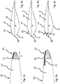
- a wind turbine rotor blade 30 is shown with a blade shell 32 and a rotor blade tip 10 of metal connected to the blade shell 32.
- the leaf shell 32 may in particular consist of two leaf shell halves.
- an impinging on a profile nose edge 20 of the rotor blade 30 air flow LS can be seen, which already detaches itself after a short course along the chord P of a surface 12 of the rotor blade tip 10.
- detachment vortices on the suction side are formed.
- the metal rotor blade tip 10 is provided with a rough surface portion 14 which extends in the vicinity of the profile nose edge 20 in a strip shape along the length L at a uniform distance from the profile nose edge 20.
- a rough surface portion 14 which extends in the vicinity of the profile nose edge 20 in a strip shape along the length L at a uniform distance from the profile nose edge 20.
- the rough surface portion 14 is in Fig. 2b formed by elevations and depressions relative to the surface 12 of the rotor blade tip.
- the pressure side D can also have a further rough surface section (not shown).
- the metal rotor blade tip 10 may, for example, as in Fig. 3a shown extend over a uniform length L along the surface 12 of the rotor blade tip 10 or as in Fig. 3b shown, an extension 22 have, which extends even further in the direction of the sheet tray 32.
- the rough surface portion extends in this case via the extension 22nd
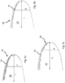
- FIGS. 4a to 4c show in the surface 12 of the rotor blade tip 10 introduced recesses 16 and elevations 18.
- the elevations 18 are particularly easy to produce by a casting process.
- the rough surface portion is located on the suction side.
- the rough surface portion may also be arranged on the pressure side or on the pressure and suction side.
- a strip-shaped, rough surface portion 14 is shown, which is formed by a plurality in the surface 12 of the rotor blade tip 10 introduced hemispherical depressions or elevations.
- Fig. 5c shows a corresponding strip-shaped surface portion 14 with cuboid elevations or depressions.
- the strip-shaped surface portion 14 is formed by cuboid depressions or elevations, which are at an angle to each other and extend in a zig-zag shape.
- the strip-shaped surface section 14 in this case has a width in the direction of the profile view P in the area from about 1 cm to 3 cm and is located in the range of the first 10% of the length of the chord P.
Landscapes
- Engineering & Computer Science (AREA)
- Physics & Mathematics (AREA)
- Fluid Mechanics (AREA)
- Life Sciences & Earth Sciences (AREA)
- Sustainable Development (AREA)
- Sustainable Energy (AREA)
- Chemical & Material Sciences (AREA)
- Combustion & Propulsion (AREA)
- Mechanical Engineering (AREA)
- General Engineering & Computer Science (AREA)
- Wind Motors (AREA)
Abstract

Description
- Die Erfindung betrifft eine Rotorblattspitze für ein Windenergieanlagenrotorblatt sowie ein Windenergieanlagenrotorblatt mit einer solchen Rotorblattspitze.
- Aerodynamische Untersuchungen an Rotorblättern von Windenergieanlagen haben ergeben, dass die aerodynamische Effizienz insbesondere im Bereich der Rotorblattspitze verringert sein kann. Grund hierfür ist in der Regel eine geringe Reynolds-Zahl an der Rotorblattspitze, die zu einem Ablösen der laminaren Luftströmung von der Rotorblattoberfläche und zur Bildung von instabilen Wirbelströmen führt. Insbesondere bilden sich dabei nahe der Profilnasenkante des Rotorblatts Ablöseblasen. Häufig wird die laminare Luftströmung dabei über einen großen Bereich von der Rotorblattoberfläche abgelöst, was zu einer geringeren Energieeffizienz führt. Derartige Strömungsabrisse und die damit verbundenen Turbulenzen sind die Hauptursache für unerwünschte Lärmentwicklung im Betrieb einer Windenergieanlage.
- Um Strömungsabrisse zu vermeiden, kann die unmittelbar an der Rotorblattoberfläche verlaufende, laminare Luftströmung gezielt in eine turbulente Luftströmung gewandelt werden, bevor sich Ablöseblasen bilden können. Eine derartige turbulente Luftströmung bringt mehr Energie in die das Rotorblatt umgebende Grenzschicht ein und erzeugt oberhalb der (Mikro-)Turbulenzen einen stabileren, laminaren Luftstrom. Es ist bekannt, zu diesem Zweck Einbuchtungen in die Oberfläche von Rotorblattschalen einzubringen bzw. mit Einbuchtungen versehene Folien nachträglich auf die Rotorblattschalen aufzubringen. Rotorblattschalen mit derartigen Unebenheiten werden beispielsweise in
EP 1 469 198 A1 ,WO 2014/0237391 WO 2012/02889081 DE 10 2006 054 683 A1 beschrieben. - Der Erfindung liegt die Aufgabe zugrunde, eine Rotorblattspitze für ein Windenergieanlagenrotorblatt zur Verfügung zu stellen, die einfach herstellbar und widerstandsfähig ist sowie störende Geräuschentwicklung vermeidet.
- Die Erfindung löst die Aufgabe durch den Gegenstand von Anspruch 1. Vorteilhafte Ausgestaltungen sind Gegenstand der Unteransprüche.
- Diese Aufgabe wird gelöst durch eine Rotorblattspitze für ein Windenergieanlagenrotorblatt, wobei die Rotorblattspitze aus Metall gefertigt ist und eine von dem Metall gebildete Oberfläche der Rotorblattspitze einen rauen Oberflächenabschnitt aufweist.
- Erfindungsgemäß ist eine Rotorblattspitze aus Metall gefertigt, insbesondere aus Aluminium. Die Rotorblattspitze kann dabei zur Verbindung mit der Blattschale eines Windenergieanlagenrotorblatts ausgebildet sein, beispielsweise zum Verkleben mit der Blattschale. Die metallene Rotorblattspitze kann als Blitzrezeptor dienen. Insbesondere kann die Rotorblattspitze das aerodynamische Profil der Blattschale fortsetzen. Erfindungsgemäß erstreckt sich über zumindest einen Teil der Oberfläche der metallenen Rotorblattspitze ein rauer Oberflächenabschnitt. Die metallene Oberfläche der Rotorblattspitze weist also eine Rauheit auf. Als Rauheit werden hierbei Unebenheiten in der Oberfläche der Rotorblattspitze verstanden. Der raue Oberflächenabschnitt kann insbesondere gegenüber der ihn umgebenden Oberflächenabschnitte der Rotorblattspitze uneben sein.
- Aufgrund des rauen Oberflächenabschnitts kann eine Strömungsablösung der entlang der Oberfläche der Rotorblattspitze strömenden Luftströmung vermieden werden. Der raue Oberflächenabschnitt erzeugt hierbei gezielt geringfügige Turbulenzen in der laminaren Luftströmung. Hierdurch bleibt die Luftströmung an der Oberfläche der Rotorblattspitze haften, wobei die oberhalb einer erzeugten turbulenten Grenzschicht verlaufende Strömung im Wesentlichen laminar bleibt. Der raue Oberflächenabschnitt in der metallenen Rotorblattspitze eliminiert somit die wesentliche Quelle der Geräuschentwicklung im Betrieb von Windenergieanlagen. Die Erfinder haben erkannt, dass es hierfür ausreichend ist, lediglich eine Rotorblattspitze abschnittsweise mit einer rauen Oberfläche zu versehen, anstatt ein vollständiges Rotorblatt derart aufzubereiten. Da erfindungsgemäß die die Rauheit bildenden Unebenheiten direkt in das Metall der Rotorblattspitze eingebracht sind, ist die erfindungsgemäße Rotorblattspitze einfacher herzustellen als die aus dem Stand der Technik bekannten Einbuchtungen in üblicherweise aus Faserverbundmaterialien gefertigten Rotorblattschalen. Zudem ist der raue Oberflächenabschnitt widerstandsfähiger gegenüber der Witterung, wie beispielsweise gegenüber Wind, Regen oder Sonneneinstrahlung. Auch nach mehreren Blitzeinschlägen kann die metallene Rotorblattspitze ihre Rauheit und damit ihre aerodynamischen Eigenschaften beibehalten. Dies ist insbesondere gegenüber den aus dem Stand der Technik bekannten, auf die Blattschale eines Rotorblatts aufgeklebten Folien von Vorteil, da diese durch die Witterung besonders stark in Mitleidenschaft gezogen werden. So kommt es häufig zur Ablösung der Folien, was nicht nur die gezielte Erzeugung von Turbulenzen verhindert, sondern auch die aerodynamischen Eigenschaften des Rotorblattes beeinträchtigt und mit einer unerwünschten Geräuschentwicklung einhergeht.
- Nach einer bevorzugten Ausgestaltung ist der raue Oberflächenabschnitt der Rotorblattspitze durch eine Vielzahl in die Oberfläche der Rotorblattspitze eingebrachter Vertiefungen und/oder Erhöhungen gebildet. Die Unebenheit des rauen Oberflächenabschnitts kann also durch in die Oberfläche der Rotorblattspitze eingebrachte Vertiefungen, Erhöhungen oder durch eine Kombination von Vertiefungen und Erhöhungen gebildet sein. Die Vertiefungen und/oder Erhöhungen können bereits bei der Herstellung der metallenen Rotorblattspitze integral mit dieser geformt sein. Auch können die Vertiefungen und/oder Erhöhungen nachträglich in die Oberfläche der metallenen Rotorblattspitze eingebracht werden, beispielsweise in einem spanenden Verfahren oder einem anderen Formgebungsverfahren. Die Rauheit der Oberfläche kann dabei insbesondere als mittlerer Abstand der Vertiefungen und/oder Erhöhungen von einer Bezugsebene definiert sein. Die Bezugsebene kann beispielsweise dem aerodynamischen Profil der Rotorblattspitze folgen, insbesondere der den rauen Oberflächenabschnitt umgebenden Oberfläche der metallenen Rotorblattspitze. Die Bezugsebene kann insbesondere eine gedachte Mittelebene sein, die eine durch die Erhöhungen/Vertiefungen gebildete Kontur derart schneidet, dass die Summe der durch die Erhöhungen/Vertiefungen bedingten Abweichungen der Kontur gegenüber der Mittelebene minimal wird.
- Nach einer Ausgestaltung erstrecken sich die Vertiefungen zwischen 0,1 mm und 1 mm in die Oberfläche der Rotorblattspitze hinein. Auch können sich die Erhöhungen zwischen 0,1 mm und 1 mm aus der Oberfläche der Rotorblattspitze heraus erstrecken. Derart geringfügige Unebenheiten sind bereits ausreichend, um die erwünschten Turbulenzen zu erzeugen und einen Strömungsabriss zu vermeiden.
- Nach einer weiteren Ausgestaltung sind die Vertiefungen und/oder Erhöhungen linsen- oder halbkugelförmig oder quaderförmig ausgebildet. Die Vertiefungen können sich also beispielsweise halbkugelförmig in die Oberfläche der Rotorblattspitze hinein erstrecken oder die Erhöhungen halbkugelförmig aus der Oberfläche heraus. Entsprechendes gilt für die linsen- oder quaderförmig ausgebildeten Unebenheiten.
- In einer Ausgestaltung sind die Vertiefungen und/oder Erhöhungen in einer Zick-Zack-Form angeordnet. Der raue Oberflächenabschnitt kann also entlang einer Zick-Zack-Linie verlaufen.
- Nach einer Ausgestaltung ist der raue Oberflächenabschnitt streifenförmig in einem gleichmäßigen Abstand von einer Profilnasenkarte angeordnet. Die Länge des streifenförmigen Oberflächenabschnitts kann beispielsweise im Bereich von 10 cm bis 100 cm liegen. Der raue Oberflächenabschnitt kann sich insbesondere entlang der gesamten Länge der metallischen Rotorblattspitze erstrecken. Der raue Oberflächenabschnitt ist streifenförmig, da seine Ausdehnung entlang der Länge der Rotorblattspitze größer ist als entlang der senkrecht zu der Länge verlaufenden Profilsehne. Beispielsweise kann der streifenförmige Oberflächenabschnitt eine Breite in Richtung der Profilsehne im Bereich von 1 cm bis 3 cm aufweisen. Ein streifenförmiger rauer Oberflächenabschnitt ist bereits ausreichend, um einen Strömungsabriss und damit störende Geräuschentwicklung zu vermeiden. Ein solcher streifenförmiger Oberflächenabschnitt ist besonders effizient und mit geringem Aufwand herstellbar. Die Anordnung des rauen Oberflächenabschnitts in einem gleichmäßigen Abstand von der Profilnasenkante bedeutet die Anordnung auf gleicher Profilsehnenposition. Der Abstand von der Profilnasenkante kann dabei im Bereich von 0% bis 50% der Länge der Profilsehne liegen, wobei sich auf 0% Länge der Profilsehne die Profilnasenkante befindet. Wie oben erläutert, ist eine Anordnung des rauen Oberflächenabschnitts davon abhängig, bei welcher Position üblicherweise eine Strömungsablösung auftreten würde. Dies ist insbesondere abhängig von dem Profilverlauf der Rotorblattspitze sowie dessen Anstellwinkel gegenüber dem Wind. Zumeist tritt eine Strömungsablösung in dem genannten Bereich von 0% bis 50% der Länge der Profilsehne auf.
- Nach einer weiteren Ausgestaltung weist die Rotorblattspitze einen sich entlang einer Profilnasenkante erstreckenden Fortsatz auf, wobei sich der raue Oberflächenabschnitt zumindest teilweise entlang des Fortsatzes erstreckt. Im an ein Windenergieanlagenrotorblatt montierten Zustand der Rotorblattspitze erstreckt sich der Fortsatz dabei in Richtung der Blattschale des Windenergieanlagenrotorblatts, im an eine Rotornabe montierten Zustand also in Richtung zu der Rotornabe hin. Der Fortsatz erstreckt sich somit im Wesentlichen entlang der Länge der Rotorblattspitze. Da sich auch der raue Oberflächenabschnitt zumindest teilweise entlang des Fortsatzes erstreckt, sind die aerodynamischen Eigenschaften der Rotorblattspitze auch im Bereich des Fortsatzes verbessert; insbesondere wird so eine unerwünschte Geräuschentwicklung vermindert. Gegenüber einer aufgerauten Oberfläche der Blattschale eines an die Rotorblattspitze anschließenden Windenergieanlagenrotorblatts ergeben sich auch hier die oben erwähnten Vorteile der einfacheren Herstellung sowie höheren Widerstandsfähigkeit des rauen Abschnitts.
- Nach einer Ausgestaltung verläuft der raue Oberflächenabschnitt auf der Saugseite und/oder auf der Druckseite der Rotorblattspitze. Der raue Oberflächenabschnitt kann also lediglich auf der Saugseite oder lediglich auf der Druckseite angeordnet sein. Auch kann auf sowohl auf der Druckseite wie auch auf der Saugseite jeweils ein rauer Oberflächenabschnitt angeordnet sein. Insbesondere kann sich der raue Oberflächenabschnitt über eine Profilnasenkante der Rotorblattspitze hinweg auf Saugseite und Druckseite erstrecken. Der raue Oberflächenabschnitt kann also beispielsweise abhängig vom Profil der Rotorblattspitze auf der Seite angeordnet sein, an der am ehesten ein Strömungsabriss auftritt. Ist der raue Oberflächenabschnitt dabei auf der Saugseite sowie auf der Druckseite angeordnet, kann auf beiden Seiten der Rotorblattspitze ein Strömungsabriss vermieden werden. Insbesondere kann so unabhängig vom Anstellwinkel, also unabhängig von der Stellung des Rotorblattes relativ zum anströmenden Wind, ein Strömungsabriss im Wesentlichen vermieden werden.
- Nach einer bevorzugten Ausgestaltung ist der raue Oberflächenabschnitt in einem Metallgießverfahren gemeinsam mit der Rotorblattspitze hergestellt. Die metallene Rotorblattspitze kann also gegossen werden, wobei durch entsprechende Ausbildung der Gießform der raue Oberflächenabschnitt direkt in die metallene Oberfläche der Rotorblattspitze eingebracht wird. Eine derartige Herstellung des rauen Oberflächenabschnitts ist nicht nur besonders einfach, sondern erzeugt auch einen besonders widerstandsfähigen Oberflächenabschnitt. Weiterhin ermöglicht das Gießverfahren die Herstellung beliebiger, auch komplexer Unebenheiten, deren Position an der Rotorblattspitze exakt reproduzierbar ist. So können insbesondere die erwähnten Erhöhungen nur durch ein solches Gießverfahren einfach hergestellt werden. Gegenüber einer nachträglichen Aufrauhung des Oberflächenabschnitts kann beim Gießverfahren ein Arbeitsschritt eingespart werden. Insbesondere zeigt sich hier der Vorteil gegenüber dem nachträglichen Einbringen von Vertiefungen oder Erhöhungen in die Blattschale eines Rotorblatts.
- Die Erfindung betrifft weiterhin ein Windenergieanlagenrotorblatt mit einer Rotorblattspitze gemäß den obigen Ausführungen. Die Rotorblattspitze ist nach einer Ausgestaltung auswechselbar mit einer Blattschale des Windenergieanlagenrotorblatts verbunden. Die Blattschale kann dabei insbesondere aus Faserverbundwerkstoffen gebildet sein und aus zwei Schalenhälften bestehen. Bei der Rotorblattspitze kann es sich insbesondere um einen Blitzrezeptor handeln, der nach Überschreiten seiner Lebenszeit problemlos auch im Betrieb der Windenergieanlage ausgewechselt werden kann.
- Die Erfindung wird im Folgenden anhand von Figuren erläutert. Es zeigen:
- Figur 1a
- eine Draufsicht auf ein Rotorblatt mit einer Rotorblattspitze ohne rauen Oberflächenabschnitt,
- Figur 1b
- eine Schnittansicht der Rotorblattspitze aus
Fig. 1a , - Figur 2a
- eine Draufsicht auf ein Rotorblatt mit einer Rotorblattspitze mit einem rauen Oberflächenabschnitt,
- Figur 2b
- eine Schnittansicht der Rotorblattspitze aus
Fig. 2a , - Figur 3a
- eine Draufsicht auf ein Rotorblatt mit einer Rotorblattspitze nach einer ersten Ausgestaltung,
- Figur 3b
- eine Draufsicht auf ein Rotorblatt mit einer Rotorblattspitze nach einer zweiten Ausgestaltung,
- Figur 4a
- eine Schnittansicht einer Rotorblattspitze mit in die Oberfläche der Rotorblattspitze eingebrachten Erhöhungen,
- Figur 4b
- eine Schnittansicht durch eine Rotorblattspitze mit in die Oberfläche der Rotorblattspitze eingebrachten Vertiefungen,
- Figur 4c
- eine Schnittansicht einer Rotorblattspitze mit in die Oberfläche der Rotorblattspitze eingebrachten Vertiefungen und Erhöhungen,
- Figur 5a
- eine Draufsicht auf eine Rotorblattspitze mit halbkugelförmigen Unebenheiten,
- Figur 5b
- eine Draufsicht auf eine Rotorblattspitze mit in Zick-Zack-Form angeordneten Unebenheiten, und
- Figur 5c
- eine Draufsicht auf eine Rotorblattspitze mit quaderförmigen Unebenheiten.
- Soweit nichts anderes angegeben ist, bezeichnen in den Figuren gleiche Bezugszeichen gleiche Gegenstände.
- In den
Figuren 1a und 1b ist ein Windenergieanlagenrotorblatt 30 mit einer Blattschale 32 und einer mit der Blattschale 32 verbundenen Rotorblattspitze 10 aus Metall dargestellt. Die Blattschale 32 kann insbesondere aus zwei Blattschalenhälften bestehen. Zudem ist eine auf eine Profilnasenkante 20 des Rotorblatts 30 auftreffende Luftströmung LS ersichtlich, die sich bereits nach kurzem Verlauf entlang der Profilsehne P von einer Oberfläche 12 der Rotorblattspitze 10 ablöst. Hierbei bilden sich ersichtlich Ablösewirbel auf der Saugseite S. - In den
Figuren 2a und 2b ist die metallene Rotorblattspitze 10 mit einem rauen Oberflächenabschnitt 14 versehen, der sich in der Nähe der Profilnasenkante 20 streifenförmig entlang der Länge L in einem gleichmäßigen Abstand von der Profilnasenkante 20 erstreckt. Wie insbesondere inFig. 2b deutlich wird, verhindert der raue Oberflächenabschnitt 14 einen Strömungsabriss der Luftströmung LS. Hierbei entstehen durch den rauen Oberflächenabschnitt 14 in der die Rotorblattspitze 10 unmittelbar umgebenden Grenzschicht Mikroturbulenzen (nicht dargestellt). Der raue Oberflächenabschnitt 14 ist inFig. 2b durch Erhöhungen und Vertiefungen gegenüber der Oberfläche 12 der Rotorblattspitze gebildet. Grundsätzlich kann auch die Druckseite D einen nicht dargestellten weiteren rauen Oberflächenabschnitt aufweisen. - Die metallene Rotorblattspitze 10 kann sich beispielsweise, wie in
Fig. 3a dargestellt, über eine gleichmäßige Länge L entlang der Oberfläche 12 der Rotorblattspitze 10 erstrecken oder wie inFig. 3b dargestellt, einen Fortsatz 22 aufweisen, der sich noch weiter in Richtung der Blattschale 32 erstreckt. Der raue Oberflächenabschnitt erstreckt sich in diesem Fall auch über den Fortsatz 22. - Die
Figuren 4a bis 4c zeigen in die Oberfläche 12 der Rotorblattspitze 10 eingebrachte Vertiefungen 16 bzw. Erhöhungen 18. Insbesondere die Erhöhungen 18 sind dabei durch ein Gießverfahren besonders einfach herstellbar. In den dargestellten Ausführungen ist der raue Oberflächenabschnitt auf der Saugseite angeordnet. Der raue Oberflächenabschnitt kann aber auch auf der Druckseite angeordnet sein oder auf der Druck- und Saugseite. - In
Fig. 5a ist ein streifenförmiger, rauer Oberflächenabschnitt 14 gezeigt, der durch eine Vielzahl in die Oberfläche 12 der Rotorblattspitze 10 eingebrachte halbkugelförmige Vertiefungen bzw. Erhöhungen gebildet ist.Fig. 5c zeigt einen entsprechenden streifenförmigen Oberflächenabschnitt 14 mit quaderförmigen Erhöhungen bzw. Vertiefungen. InFig. 5b ist der streifenförmige Oberflächenabschnitt 14 durch quaderförmige Vertiefungen oder Erhöhungen gebildet, die in einem Winkel zueinander stehen und in einer Zick-Zack-Form verlaufen. Der streifenförmige Oberflächenabschnitt 14 weist hierbei eine Breite in Richtung der Profilsehen P im Bereich von ca. 1 cm bis 3 cm auf und ist im Bereich der ersten 10% der Länge der Profilsehne P angeordnet. -
- 10
- Rotorblattspitze
- 12
- Oberfläche
- 14
- rauer Oberflächenabschnitt
- 16
- Vertiefungen
- 18
- Erhöhungen
- 20
- Profilnasenkante
- 22
- Fortsatz
- 30
- Windenergieanlagenrotorblatt
- 32
- Blattschale
- P
- Profilsehne
- L
- Länge
- S
- Saugseite
- D
- Druckseite
- LS
- Luftströmung
Claims (15)
- Rotorblattspitze für ein Windenergieanlagenrotorblatt (30), wobei die Rotorblattspitze (10) aus Metall gefertigt ist und eine von dem Metall gebildete Oberfläche (12) der Rotorblattspitze (10) einen rauen Oberflächenabschnitt (14) aufweist.
- Rotorblattspitze nach Anspruch 1, dadurch gekennzeichnet, dass der raue Oberflächenabschnitt (14) der Rotorblattspitze (10) durch eine Vielzahl in die Oberfläche (12) der Rotorblattspitze (10) eingebrachter Vertiefungen (16) und/oder Erhöhungen (18) gebildet ist.
- Rotorblattspitze nach Anspruch 2, dadurch gekennzeichnet, dass sich die Vertiefungen (16) zwischen 0,1 mm und 1 mm in die Oberfläche (12) der Rotorblattspitze (10) hinein erstrecken und/oder dass sich die Erhöhungen (18) zwischen 0,1 mm und 1 mm aus der Oberfläche (12) der Rotorblattspitze (10) hinaus erstrecken.
- Rotorblattspitze nach Anspruch 2 oder 3, dadurch gekennzeichnet, dass die Vertiefungen (16) und/oder Erhöhungen (18) linsen- oder halbkugelförmig oder quaderförmig ausgebildet sind.
- Rotorblattspitze nach einem der Ansprüche 2 bis 4, dadurch gekennzeichnet, dass die Vertiefungen (16) und/oder Erhöhungen (18) in einer Zick-Zack-Form angeordnet sind.
- Rotorblattspitze nach einem der vorhergehenden Ansprüche, dadurch gekennzeichnet, dass der raue Oberflächenabschnitt (14) streifenförmig in einem gleichmäßigen Abstand von einer Profilnasenkante (20), insbesondere entlang der gesamten Länge (L) der Rotorblattspitze (10), angeordnet ist.
- Rotorblattspitze nach Anspruch 6, dadurch gekennzeichnet, dass der Abstand in einem Bereich von 0% bis 50% der Länge der Profilsehne (P) liegt.
- Rotorblattspitze nach Anspruch 6 oder 7, dadurch gekennzeichnet, dass der streifenförmige Oberflächenabschnitt (14) eine Breite in Richtung der Profilsehne (P) im Bereich von 1 cm bis 3 cm aufweist.
- Rotorblattspitze nach einem der vorhergehenden Ansprüche, dadurch gekennzeichnet, dass die Rotorblattspitze (10) einen sich entlang einer Profilnasenkante (20) erstreckenden Fortsatz (22) aufweist, wobei sich der raue Oberflächenabschnitt (14) zumindest teilweise entlang des Fortsatzes (22) erstreckt.
- Rotorblattspitze nach einem der vorhergehenden Ansprüche, dadurch gekennzeichnet, dass der raue Oberflächenabschnitt (14) auf der Saugseite (S) und/oder auf der Druckseite (D) der Rotorblattspitze (10) verläuft.
- Rotorblattspitze nach Anspruch 10, dadurch gekennzeichnet, dass sich der raue Oberflächenabschnitt (14) über eine Profilnasenkante (20) der Rotorblattspitze (10) hinweg auf der Saugseite (S) und der Druckseite (D) erstreckt.
- Rotorblattspitze nach einem der vorhergehenden Ansprüche, dadurch gekennzeichnet, dass der raue Oberflächenabschnitt (14) in einem Metallgießverfahren gemeinsam mit der Rotorblattspitze (10) hergestellt ist.
- Rotorblattspitze nach der Ansprüche 1 bis 11, dadurch gekennzeichnet, dass der raue Oberflächenabschnitt (14) durch nachträgliche Bearbeitung in die Rotorblattspitze (10) eingebracht ist.
- Windenergieanlagenrotorblatt mit einer Rotorblattspitze (10) nach einem der vorhergehenden Ansprüche.
- Windenergieanlagenrotorblatt nach Anspruch 14, dadurch gekennzeichnet, dass die Rotorblattspitze (10) auswechselbar mit einer Blattschale (32) des Windenergieanlagenrotorblatts (30) verbunden ist.
Priority Applications (3)
| Application Number | Priority Date | Filing Date | Title |
|---|---|---|---|
| EP17169755.0A EP3399182B1 (de) | 2017-05-05 | 2017-05-05 | Geräuscharme rotorblattspitze |
| DK17169755.0T DK3399182T3 (da) | 2017-05-05 | 2017-05-05 | Spids til rotorblad med lav støj |
| ES17169755T ES2844592T3 (es) | 2017-05-05 | 2017-05-05 | Punta de pala de rotor silenciosa |
Applications Claiming Priority (1)
| Application Number | Priority Date | Filing Date | Title |
|---|---|---|---|
| EP17169755.0A EP3399182B1 (de) | 2017-05-05 | 2017-05-05 | Geräuscharme rotorblattspitze |
Publications (2)
| Publication Number | Publication Date |
|---|---|
| EP3399182A1 true EP3399182A1 (de) | 2018-11-07 |
| EP3399182B1 EP3399182B1 (de) | 2020-11-11 |
Family
ID=58671535
Family Applications (1)
| Application Number | Title | Priority Date | Filing Date |
|---|---|---|---|
| EP17169755.0A Active EP3399182B1 (de) | 2017-05-05 | 2017-05-05 | Geräuscharme rotorblattspitze |
Country Status (3)
| Country | Link |
|---|---|
| EP (1) | EP3399182B1 (de) |
| DK (1) | DK3399182T3 (de) |
| ES (1) | ES2844592T3 (de) |
Citations (8)
| Publication number | Priority date | Publication date | Assignee | Title |
|---|---|---|---|---|
| EP1469198A1 (de) | 2003-04-17 | 2004-10-20 | Eugen Radtke | Auftriebsverbessernde Oberflächenstruktur für Windenergiekonverter |
| DE102005019905A1 (de) * | 2005-04-29 | 2006-11-02 | Nordex Energy Gmbh | Rotorblatt für eine Windenergieanlage |
| DE102006054683A1 (de) | 2005-11-17 | 2007-05-24 | General Electric Co. | Rotorblatt mit aerodynamischen Elementen für eine Windkraftanlage |
| US20080193292A1 (en) * | 2007-02-08 | 2008-08-14 | Ronny Stam | Rotor blade with a lightning protection unit, wind energy system having the same and a method for constructing a rotor blade |
| EP2196665A2 (de) * | 2008-12-15 | 2010-06-16 | REpower Systems AG | Rotorblatt einer Windenergieanlage mit einem Turbulator |
| WO2012028890A1 (en) | 2010-09-01 | 2012-03-08 | Theodoros Toulas | Wind turbine blades with dimples |
| WO2014023739A1 (en) | 2012-08-09 | 2014-02-13 | New World Energy Enterprises Limited | A blade for a rotary machine |
| EP2770197A2 (de) * | 2003-09-29 | 2014-08-27 | Vestas Wind Systems A/S | Windturbinenschaufel, Windturbine, Verfahren zur Bereitstellung von Blitzableitermitteln an einer Windturbinenschaufel und Verwendung davon |
-
2017
- 2017-05-05 EP EP17169755.0A patent/EP3399182B1/de active Active
- 2017-05-05 ES ES17169755T patent/ES2844592T3/es active Active
- 2017-05-05 DK DK17169755.0T patent/DK3399182T3/da active
Patent Citations (8)
| Publication number | Priority date | Publication date | Assignee | Title |
|---|---|---|---|---|
| EP1469198A1 (de) | 2003-04-17 | 2004-10-20 | Eugen Radtke | Auftriebsverbessernde Oberflächenstruktur für Windenergiekonverter |
| EP2770197A2 (de) * | 2003-09-29 | 2014-08-27 | Vestas Wind Systems A/S | Windturbinenschaufel, Windturbine, Verfahren zur Bereitstellung von Blitzableitermitteln an einer Windturbinenschaufel und Verwendung davon |
| DE102005019905A1 (de) * | 2005-04-29 | 2006-11-02 | Nordex Energy Gmbh | Rotorblatt für eine Windenergieanlage |
| DE102006054683A1 (de) | 2005-11-17 | 2007-05-24 | General Electric Co. | Rotorblatt mit aerodynamischen Elementen für eine Windkraftanlage |
| US20080193292A1 (en) * | 2007-02-08 | 2008-08-14 | Ronny Stam | Rotor blade with a lightning protection unit, wind energy system having the same and a method for constructing a rotor blade |
| EP2196665A2 (de) * | 2008-12-15 | 2010-06-16 | REpower Systems AG | Rotorblatt einer Windenergieanlage mit einem Turbulator |
| WO2012028890A1 (en) | 2010-09-01 | 2012-03-08 | Theodoros Toulas | Wind turbine blades with dimples |
| WO2014023739A1 (en) | 2012-08-09 | 2014-02-13 | New World Energy Enterprises Limited | A blade for a rotary machine |
Also Published As
| Publication number | Publication date |
|---|---|
| EP3399182B1 (de) | 2020-11-11 |
| DK3399182T3 (da) | 2021-02-15 |
| ES2844592T3 (es) | 2021-07-22 |
Similar Documents
| Publication | Publication Date | Title |
|---|---|---|
| EP1583904B1 (de) | Windturbinenrotorblatt mit verringerter schallemission | |
| DE102010038074B4 (de) | Turbinenschaufelblatt | |
| EP1514023B1 (de) | Windenergieanlage | |
| EP2942521B1 (de) | Reparaturverfahren für vortexgenerator und ein bausatz dafür | |
| DE10347802B3 (de) | Rotorblatt für eine Windkraftanlage | |
| EP2473743B1 (de) | Verdichterlaufschaufel für einen axialverdichter | |
| DE102006055090A1 (de) | Flügelendform für einen Flügel, insbesondere von Luftfahrzeugen | |
| DE102013207640B4 (de) | Windenergieanlagen-Rotorblatt | |
| DE102010036154A1 (de) | Luft absaugende Fahrzeugrumpfkomponente, Verfahren zum Herstellen einer Luft absaugenden Fahrzeugrumpfkomponente und Fahrzeug, insbesondere Flugzeug, mit einer Luft absaugenden Fahrzeugrumpfkomponente | |
| DE102015008813A1 (de) | Vortexgenerator | |
| EP1760310A1 (de) | Rotorblatt einer Windenergieanlage | |
| DE102011050777A1 (de) | Rotor und Rotorblatt für eine Windkraftanlage | |
| DE102012104240B4 (de) | Hybridströmungs-Schaufeldesigns | |
| EP3510275A1 (de) | Windenergieanlagen-rotorblatt | |
| DE102010048266A1 (de) | Flügel mit einem Strömungszaun und Flugzeug mit solchen Tragflügeln | |
| EP3039246B1 (de) | Turbinenschaufel | |
| EP2489837A1 (de) | Drosseleinsatz für Turbinenschaufel und zugehörige Turbinenschaufel | |
| EP2679803B1 (de) | Windenergieanlagenrotorblatt mit einer dicken profilhinterkante | |
| EP3460187A1 (de) | Schaufel für eine strömungsmaschine | |
| EP3399182B1 (de) | Geräuscharme rotorblattspitze | |
| DE102008014702A1 (de) | Motoraufhängung für einen Axiallüfter und Verfahren zur Herstellung einer Motoraufhängung | |
| EP3232001A1 (de) | Laufschaufel für eine turbine | |
| EP3954892A2 (de) | Rotorblatt für eine windenergieanlage, rotor für eine windenergieanlage, bauwerk und windenergieanlage | |
| EP4136323B1 (de) | Turbinenschaufel und zugehöriges herstellungsverfahren | |
| DE102018123362A1 (de) | Windenergieanlagenrotorblatt |
Legal Events
| Date | Code | Title | Description |
|---|---|---|---|
| PUAI | Public reference made under article 153(3) epc to a published international application that has entered the european phase |
Free format text: ORIGINAL CODE: 0009012 |
|
| STAA | Information on the status of an ep patent application or granted ep patent |
Free format text: STATUS: THE APPLICATION HAS BEEN PUBLISHED |
|
| AK | Designated contracting states |
Kind code of ref document: A1 Designated state(s): AL AT BE BG CH CY CZ DE DK EE ES FI FR GB GR HR HU IE IS IT LI LT LU LV MC MK MT NL NO PL PT RO RS SE SI SK SM TR |
|
| AX | Request for extension of the european patent |
Extension state: BA ME |
|
| STAA | Information on the status of an ep patent application or granted ep patent |
Free format text: STATUS: REQUEST FOR EXAMINATION WAS MADE |
|
| STAA | Information on the status of an ep patent application or granted ep patent |
Free format text: STATUS: EXAMINATION IS IN PROGRESS |
|
| 17P | Request for examination filed |
Effective date: 20190507 |
|
| RBV | Designated contracting states (corrected) |
Designated state(s): AL AT BE BG CH CY CZ DE DK EE ES FI FR GB GR HR HU IE IS IT LI LT LU LV MC MK MT NL NO PL PT RO RS SE SI SK SM TR |
|
| 17Q | First examination report despatched |
Effective date: 20190527 |
|
| GRAP | Despatch of communication of intention to grant a patent |
Free format text: ORIGINAL CODE: EPIDOSNIGR1 |
|
| STAA | Information on the status of an ep patent application or granted ep patent |
Free format text: STATUS: GRANT OF PATENT IS INTENDED |
|
| INTG | Intention to grant announced |
Effective date: 20200615 |
|
| GRAS | Grant fee paid |
Free format text: ORIGINAL CODE: EPIDOSNIGR3 |
|
| GRAA | (expected) grant |
Free format text: ORIGINAL CODE: 0009210 |
|
| STAA | Information on the status of an ep patent application or granted ep patent |
Free format text: STATUS: THE PATENT HAS BEEN GRANTED |
|
| AK | Designated contracting states |
Kind code of ref document: B1 Designated state(s): AL AT BE BG CH CY CZ DE DK EE ES FI FR GB GR HR HU IE IS IT LI LT LU LV MC MK MT NL NO PL PT RO RS SE SI SK SM TR |
|
| REG | Reference to a national code |
Ref country code: GB Ref legal event code: FG4D Free format text: NOT ENGLISH |
|
| REG | Reference to a national code |
Ref country code: CH Ref legal event code: EP |
|
| REG | Reference to a national code |
Ref country code: AT Ref legal event code: REF Ref document number: 1333714 Country of ref document: AT Kind code of ref document: T Effective date: 20201115 |
|
| REG | Reference to a national code |
Ref country code: DE Ref legal event code: R096 Ref document number: 502017008112 Country of ref document: DE |
|
| REG | Reference to a national code |
Ref country code: IE Ref legal event code: FG4D Free format text: LANGUAGE OF EP DOCUMENT: GERMAN |
|
| REG | Reference to a national code |
Ref country code: DE Ref legal event code: R082 Ref document number: 502017008112 Country of ref document: DE Representative=s name: HAUCK PATENTANWALTSPARTNERSCHAFT MBB, DE Ref country code: DE Ref legal event code: R081 Ref document number: 502017008112 Country of ref document: DE Owner name: NORDEX ENERGY SE & CO. KG, DE Free format text: FORMER OWNER: NORDEX ENERGY GMBH, 22419 HAMBURG, DE |
|
| REG | Reference to a national code |
Ref country code: DK Ref legal event code: T3 Effective date: 20210210 |
|
| RAP2 | Party data changed (patent owner data changed or rights of a patent transferred) |
Owner name: NORDEX ENERGY SE & CO. KG |
|
| REG | Reference to a national code |
Ref country code: NL Ref legal event code: MP Effective date: 20201111 |
|
| PG25 | Lapsed in a contracting state [announced via postgrant information from national office to epo] |
Ref country code: PT Free format text: LAPSE BECAUSE OF FAILURE TO SUBMIT A TRANSLATION OF THE DESCRIPTION OR TO PAY THE FEE WITHIN THE PRESCRIBED TIME-LIMIT Effective date: 20210311 Ref country code: RS Free format text: LAPSE BECAUSE OF FAILURE TO SUBMIT A TRANSLATION OF THE DESCRIPTION OR TO PAY THE FEE WITHIN THE PRESCRIBED TIME-LIMIT Effective date: 20201111 Ref country code: NO Free format text: LAPSE BECAUSE OF FAILURE TO SUBMIT A TRANSLATION OF THE DESCRIPTION OR TO PAY THE FEE WITHIN THE PRESCRIBED TIME-LIMIT Effective date: 20210211 Ref country code: FI Free format text: LAPSE BECAUSE OF FAILURE TO SUBMIT A TRANSLATION OF THE DESCRIPTION OR TO PAY THE FEE WITHIN THE PRESCRIBED TIME-LIMIT Effective date: 20201111 Ref country code: GR Free format text: LAPSE BECAUSE OF FAILURE TO SUBMIT A TRANSLATION OF THE DESCRIPTION OR TO PAY THE FEE WITHIN THE PRESCRIBED TIME-LIMIT Effective date: 20210212 |
|
| PG25 | Lapsed in a contracting state [announced via postgrant information from national office to epo] |
Ref country code: BG Free format text: LAPSE BECAUSE OF FAILURE TO SUBMIT A TRANSLATION OF THE DESCRIPTION OR TO PAY THE FEE WITHIN THE PRESCRIBED TIME-LIMIT Effective date: 20210211 Ref country code: LV Free format text: LAPSE BECAUSE OF FAILURE TO SUBMIT A TRANSLATION OF THE DESCRIPTION OR TO PAY THE FEE WITHIN THE PRESCRIBED TIME-LIMIT Effective date: 20201111 Ref country code: IS Free format text: LAPSE BECAUSE OF FAILURE TO SUBMIT A TRANSLATION OF THE DESCRIPTION OR TO PAY THE FEE WITHIN THE PRESCRIBED TIME-LIMIT Effective date: 20210311 Ref country code: PL Free format text: LAPSE BECAUSE OF FAILURE TO SUBMIT A TRANSLATION OF THE DESCRIPTION OR TO PAY THE FEE WITHIN THE PRESCRIBED TIME-LIMIT Effective date: 20201111 Ref country code: SE Free format text: LAPSE BECAUSE OF FAILURE TO SUBMIT A TRANSLATION OF THE DESCRIPTION OR TO PAY THE FEE WITHIN THE PRESCRIBED TIME-LIMIT Effective date: 20201111 |
|
| REG | Reference to a national code |
Ref country code: LT Ref legal event code: MG9D |
|
| PG25 | Lapsed in a contracting state [announced via postgrant information from national office to epo] |
Ref country code: HR Free format text: LAPSE BECAUSE OF FAILURE TO SUBMIT A TRANSLATION OF THE DESCRIPTION OR TO PAY THE FEE WITHIN THE PRESCRIBED TIME-LIMIT Effective date: 20201111 |
|
| REG | Reference to a national code |
Ref country code: ES Ref legal event code: FG2A Ref document number: 2844592 Country of ref document: ES Kind code of ref document: T3 Effective date: 20210722 |
|
| PG25 | Lapsed in a contracting state [announced via postgrant information from national office to epo] |
Ref country code: SK Free format text: LAPSE BECAUSE OF FAILURE TO SUBMIT A TRANSLATION OF THE DESCRIPTION OR TO PAY THE FEE WITHIN THE PRESCRIBED TIME-LIMIT Effective date: 20201111 Ref country code: RO Free format text: LAPSE BECAUSE OF FAILURE TO SUBMIT A TRANSLATION OF THE DESCRIPTION OR TO PAY THE FEE WITHIN THE PRESCRIBED TIME-LIMIT Effective date: 20201111 Ref country code: SM Free format text: LAPSE BECAUSE OF FAILURE TO SUBMIT A TRANSLATION OF THE DESCRIPTION OR TO PAY THE FEE WITHIN THE PRESCRIBED TIME-LIMIT Effective date: 20201111 Ref country code: LT Free format text: LAPSE BECAUSE OF FAILURE TO SUBMIT A TRANSLATION OF THE DESCRIPTION OR TO PAY THE FEE WITHIN THE PRESCRIBED TIME-LIMIT Effective date: 20201111 Ref country code: EE Free format text: LAPSE BECAUSE OF FAILURE TO SUBMIT A TRANSLATION OF THE DESCRIPTION OR TO PAY THE FEE WITHIN THE PRESCRIBED TIME-LIMIT Effective date: 20201111 Ref country code: CZ Free format text: LAPSE BECAUSE OF FAILURE TO SUBMIT A TRANSLATION OF THE DESCRIPTION OR TO PAY THE FEE WITHIN THE PRESCRIBED TIME-LIMIT Effective date: 20201111 |
|
| REG | Reference to a national code |
Ref country code: DE Ref legal event code: R097 Ref document number: 502017008112 Country of ref document: DE |
|
| PLBE | No opposition filed within time limit |
Free format text: ORIGINAL CODE: 0009261 |
|
| STAA | Information on the status of an ep patent application or granted ep patent |
Free format text: STATUS: NO OPPOSITION FILED WITHIN TIME LIMIT |
|
| 26N | No opposition filed |
Effective date: 20210812 |
|
| PG25 | Lapsed in a contracting state [announced via postgrant information from national office to epo] |
Ref country code: AL Free format text: LAPSE BECAUSE OF FAILURE TO SUBMIT A TRANSLATION OF THE DESCRIPTION OR TO PAY THE FEE WITHIN THE PRESCRIBED TIME-LIMIT Effective date: 20201111 Ref country code: NL Free format text: LAPSE BECAUSE OF FAILURE TO SUBMIT A TRANSLATION OF THE DESCRIPTION OR TO PAY THE FEE WITHIN THE PRESCRIBED TIME-LIMIT Effective date: 20201111 Ref country code: IT Free format text: LAPSE BECAUSE OF FAILURE TO SUBMIT A TRANSLATION OF THE DESCRIPTION OR TO PAY THE FEE WITHIN THE PRESCRIBED TIME-LIMIT Effective date: 20201111 |
|
| PG25 | Lapsed in a contracting state [announced via postgrant information from national office to epo] |
Ref country code: SI Free format text: LAPSE BECAUSE OF FAILURE TO SUBMIT A TRANSLATION OF THE DESCRIPTION OR TO PAY THE FEE WITHIN THE PRESCRIBED TIME-LIMIT Effective date: 20201111 |
|
| REG | Reference to a national code |
Ref country code: CH Ref legal event code: PL |
|
| GBPC | Gb: european patent ceased through non-payment of renewal fee |
Effective date: 20210505 |
|
| PG25 | Lapsed in a contracting state [announced via postgrant information from national office to epo] |
Ref country code: CH Free format text: LAPSE BECAUSE OF NON-PAYMENT OF DUE FEES Effective date: 20210531 Ref country code: LU Free format text: LAPSE BECAUSE OF NON-PAYMENT OF DUE FEES Effective date: 20210505 Ref country code: LI Free format text: LAPSE BECAUSE OF NON-PAYMENT OF DUE FEES Effective date: 20210531 Ref country code: MC Free format text: LAPSE BECAUSE OF FAILURE TO SUBMIT A TRANSLATION OF THE DESCRIPTION OR TO PAY THE FEE WITHIN THE PRESCRIBED TIME-LIMIT Effective date: 20201111 |
|
| REG | Reference to a national code |
Ref country code: BE Ref legal event code: MM Effective date: 20210531 |
|
| PG25 | Lapsed in a contracting state [announced via postgrant information from national office to epo] |
Ref country code: IE Free format text: LAPSE BECAUSE OF NON-PAYMENT OF DUE FEES Effective date: 20210505 Ref country code: GB Free format text: LAPSE BECAUSE OF NON-PAYMENT OF DUE FEES Effective date: 20210505 |
|
| PG25 | Lapsed in a contracting state [announced via postgrant information from national office to epo] |
Ref country code: IS Free format text: LAPSE BECAUSE OF FAILURE TO SUBMIT A TRANSLATION OF THE DESCRIPTION OR TO PAY THE FEE WITHIN THE PRESCRIBED TIME-LIMIT Effective date: 20210311 Ref country code: FR Free format text: LAPSE BECAUSE OF NON-PAYMENT OF DUE FEES Effective date: 20210531 |
|
| PG25 | Lapsed in a contracting state [announced via postgrant information from national office to epo] |
Ref country code: BE Free format text: LAPSE BECAUSE OF NON-PAYMENT OF DUE FEES Effective date: 20210531 |
|
| PG25 | Lapsed in a contracting state [announced via postgrant information from national office to epo] |
Ref country code: CY Free format text: LAPSE BECAUSE OF FAILURE TO SUBMIT A TRANSLATION OF THE DESCRIPTION OR TO PAY THE FEE WITHIN THE PRESCRIBED TIME-LIMIT Effective date: 20201111 |
|
| P01 | Opt-out of the competence of the unified patent court (upc) registered |
Effective date: 20230602 |
|
| REG | Reference to a national code |
Ref country code: AT Ref legal event code: MM01 Ref document number: 1333714 Country of ref document: AT Kind code of ref document: T Effective date: 20220505 |
|
| PG25 | Lapsed in a contracting state [announced via postgrant information from national office to epo] |
Ref country code: HU Free format text: LAPSE BECAUSE OF FAILURE TO SUBMIT A TRANSLATION OF THE DESCRIPTION OR TO PAY THE FEE WITHIN THE PRESCRIBED TIME-LIMIT; INVALID AB INITIO Effective date: 20170505 Ref country code: AT Free format text: LAPSE BECAUSE OF NON-PAYMENT OF DUE FEES Effective date: 20220505 |
|
| PG25 | Lapsed in a contracting state [announced via postgrant information from national office to epo] |
Ref country code: MK Free format text: LAPSE BECAUSE OF FAILURE TO SUBMIT A TRANSLATION OF THE DESCRIPTION OR TO PAY THE FEE WITHIN THE PRESCRIBED TIME-LIMIT Effective date: 20201111 |
|
| PG25 | Lapsed in a contracting state [announced via postgrant information from national office to epo] |
Ref country code: MT Free format text: LAPSE BECAUSE OF FAILURE TO SUBMIT A TRANSLATION OF THE DESCRIPTION OR TO PAY THE FEE WITHIN THE PRESCRIBED TIME-LIMIT Effective date: 20201111 |
|
| PGFP | Annual fee paid to national office [announced via postgrant information from national office to epo] |
Ref country code: DE Payment date: 20250519 Year of fee payment: 9 |
|
| PGFP | Annual fee paid to national office [announced via postgrant information from national office to epo] |
Ref country code: ES Payment date: 20250616 Year of fee payment: 9 Ref country code: DK Payment date: 20250521 Year of fee payment: 9 |
|
| PG25 | Lapsed in a contracting state [announced via postgrant information from national office to epo] |
Ref country code: TR Free format text: LAPSE BECAUSE OF FAILURE TO SUBMIT A TRANSLATION OF THE DESCRIPTION OR TO PAY THE FEE WITHIN THE PRESCRIBED TIME-LIMIT Effective date: 20201111 |