EP3399173A1 - Method to control a hybrid drive system for a road vehicle - Google Patents
Method to control a hybrid drive system for a road vehicle Download PDFInfo
- Publication number
- EP3399173A1 EP3399173A1 EP18170931.2A EP18170931A EP3399173A1 EP 3399173 A1 EP3399173 A1 EP 3399173A1 EP 18170931 A EP18170931 A EP 18170931A EP 3399173 A1 EP3399173 A1 EP 3399173A1
- Authority
- EP
- European Patent Office
- Prior art keywords
- internal combustion
- heat engine
- combustion heat
- electric machine
- torque
- Prior art date
- Legal status (The legal status is an assumption and is not a legal conclusion. Google has not performed a legal analysis and makes no representation as to the accuracy of the status listed.)
- Granted
Links
Images

Classifications
-
- B—PERFORMING OPERATIONS; TRANSPORTING
- B60—VEHICLES IN GENERAL
- B60W—CONJOINT CONTROL OF VEHICLE SUB-UNITS OF DIFFERENT TYPE OR DIFFERENT FUNCTION; CONTROL SYSTEMS SPECIALLY ADAPTED FOR HYBRID VEHICLES; ROAD VEHICLE DRIVE CONTROL SYSTEMS FOR PURPOSES NOT RELATED TO THE CONTROL OF A PARTICULAR SUB-UNIT
- B60W20/00—Control systems specially adapted for hybrid vehicles
- B60W20/20—Control strategies involving selection of hybrid configuration, e.g. selection between series or parallel configuration
-
- B—PERFORMING OPERATIONS; TRANSPORTING
- B61—RAILWAYS
- B61C—LOCOMOTIVES; MOTOR RAILCARS
- B61C7/00—Other locomotives or motor railcars characterised by the type of motive power plant used; Locomotives or motor railcars with two or more different kinds or types of motive power
-
- B—PERFORMING OPERATIONS; TRANSPORTING
- B60—VEHICLES IN GENERAL
- B60W—CONJOINT CONTROL OF VEHICLE SUB-UNITS OF DIFFERENT TYPE OR DIFFERENT FUNCTION; CONTROL SYSTEMS SPECIALLY ADAPTED FOR HYBRID VEHICLES; ROAD VEHICLE DRIVE CONTROL SYSTEMS FOR PURPOSES NOT RELATED TO THE CONTROL OF A PARTICULAR SUB-UNIT
- B60W10/00—Conjoint control of vehicle sub-units of different type or different function
- B60W10/04—Conjoint control of vehicle sub-units of different type or different function including control of propulsion units
- B60W10/06—Conjoint control of vehicle sub-units of different type or different function including control of propulsion units including control of combustion engines
-
- B—PERFORMING OPERATIONS; TRANSPORTING
- B60—VEHICLES IN GENERAL
- B60W—CONJOINT CONTROL OF VEHICLE SUB-UNITS OF DIFFERENT TYPE OR DIFFERENT FUNCTION; CONTROL SYSTEMS SPECIALLY ADAPTED FOR HYBRID VEHICLES; ROAD VEHICLE DRIVE CONTROL SYSTEMS FOR PURPOSES NOT RELATED TO THE CONTROL OF A PARTICULAR SUB-UNIT
- B60W10/00—Conjoint control of vehicle sub-units of different type or different function
- B60W10/04—Conjoint control of vehicle sub-units of different type or different function including control of propulsion units
- B60W10/08—Conjoint control of vehicle sub-units of different type or different function including control of propulsion units including control of electric propulsion units, e.g. motors or generators
-
- F—MECHANICAL ENGINEERING; LIGHTING; HEATING; WEAPONS; BLASTING
- F02—COMBUSTION ENGINES; HOT-GAS OR COMBUSTION-PRODUCT ENGINE PLANTS
- F02B—INTERNAL-COMBUSTION PISTON ENGINES; COMBUSTION ENGINES IN GENERAL
- F02B39/00—Component parts, details, or accessories relating to, driven charging or scavenging pumps, not provided for in groups F02B33/00 - F02B37/00
- F02B39/02—Drives of pumps; Varying pump drive gear ratio
- F02B39/08—Non-mechanical drives, e.g. fluid drives having variable gear ratio
- F02B39/10—Non-mechanical drives, e.g. fluid drives having variable gear ratio electric
-
- F—MECHANICAL ENGINEERING; LIGHTING; HEATING; WEAPONS; BLASTING
- F02—COMBUSTION ENGINES; HOT-GAS OR COMBUSTION-PRODUCT ENGINE PLANTS
- F02B—INTERNAL-COMBUSTION PISTON ENGINES; COMBUSTION ENGINES IN GENERAL
- F02B41/00—Engines characterised by special means for improving conversion of heat or pressure energy into mechanical power
- F02B41/02—Engines with prolonged expansion
- F02B41/10—Engines with prolonged expansion in exhaust turbines
-
- F—MECHANICAL ENGINEERING; LIGHTING; HEATING; WEAPONS; BLASTING
- F02—COMBUSTION ENGINES; HOT-GAS OR COMBUSTION-PRODUCT ENGINE PLANTS
- F02D—CONTROLLING COMBUSTION ENGINES
- F02D41/00—Electrical control of supply of combustible mixture or its constituents
- F02D41/0002—Controlling intake air
- F02D41/0007—Controlling intake air for control of turbo-charged or super-charged engines
-
- B—PERFORMING OPERATIONS; TRANSPORTING
- B60—VEHICLES IN GENERAL
- B60W—CONJOINT CONTROL OF VEHICLE SUB-UNITS OF DIFFERENT TYPE OR DIFFERENT FUNCTION; CONTROL SYSTEMS SPECIALLY ADAPTED FOR HYBRID VEHICLES; ROAD VEHICLE DRIVE CONTROL SYSTEMS FOR PURPOSES NOT RELATED TO THE CONTROL OF A PARTICULAR SUB-UNIT
- B60W2540/00—Input parameters relating to occupants
- B60W2540/10—Accelerator pedal position
-
- B—PERFORMING OPERATIONS; TRANSPORTING
- B60—VEHICLES IN GENERAL
- B60W—CONJOINT CONTROL OF VEHICLE SUB-UNITS OF DIFFERENT TYPE OR DIFFERENT FUNCTION; CONTROL SYSTEMS SPECIALLY ADAPTED FOR HYBRID VEHICLES; ROAD VEHICLE DRIVE CONTROL SYSTEMS FOR PURPOSES NOT RELATED TO THE CONTROL OF A PARTICULAR SUB-UNIT
- B60W2710/00—Output or target parameters relating to a particular sub-units
- B60W2710/06—Combustion engines, Gas turbines
- B60W2710/0605—Throttle position
-
- B—PERFORMING OPERATIONS; TRANSPORTING
- B60—VEHICLES IN GENERAL
- B60W—CONJOINT CONTROL OF VEHICLE SUB-UNITS OF DIFFERENT TYPE OR DIFFERENT FUNCTION; CONTROL SYSTEMS SPECIALLY ADAPTED FOR HYBRID VEHICLES; ROAD VEHICLE DRIVE CONTROL SYSTEMS FOR PURPOSES NOT RELATED TO THE CONTROL OF A PARTICULAR SUB-UNIT
- B60W2710/00—Output or target parameters relating to a particular sub-units
- B60W2710/06—Combustion engines, Gas turbines
- B60W2710/0616—Position of fuel or air injector
- B60W2710/0622—Air-fuel ratio
-
- B—PERFORMING OPERATIONS; TRANSPORTING
- B60—VEHICLES IN GENERAL
- B60W—CONJOINT CONTROL OF VEHICLE SUB-UNITS OF DIFFERENT TYPE OR DIFFERENT FUNCTION; CONTROL SYSTEMS SPECIALLY ADAPTED FOR HYBRID VEHICLES; ROAD VEHICLE DRIVE CONTROL SYSTEMS FOR PURPOSES NOT RELATED TO THE CONTROL OF A PARTICULAR SUB-UNIT
- B60W2710/00—Output or target parameters relating to a particular sub-units
- B60W2710/06—Combustion engines, Gas turbines
- B60W2710/0644—Engine speed
-
- B—PERFORMING OPERATIONS; TRANSPORTING
- B60—VEHICLES IN GENERAL
- B60W—CONJOINT CONTROL OF VEHICLE SUB-UNITS OF DIFFERENT TYPE OR DIFFERENT FUNCTION; CONTROL SYSTEMS SPECIALLY ADAPTED FOR HYBRID VEHICLES; ROAD VEHICLE DRIVE CONTROL SYSTEMS FOR PURPOSES NOT RELATED TO THE CONTROL OF A PARTICULAR SUB-UNIT
- B60W2710/00—Output or target parameters relating to a particular sub-units
- B60W2710/06—Combustion engines, Gas turbines
- B60W2710/0666—Engine torque
-
- B—PERFORMING OPERATIONS; TRANSPORTING
- B60—VEHICLES IN GENERAL
- B60W—CONJOINT CONTROL OF VEHICLE SUB-UNITS OF DIFFERENT TYPE OR DIFFERENT FUNCTION; CONTROL SYSTEMS SPECIALLY ADAPTED FOR HYBRID VEHICLES; ROAD VEHICLE DRIVE CONTROL SYSTEMS FOR PURPOSES NOT RELATED TO THE CONTROL OF A PARTICULAR SUB-UNIT
- B60W2710/00—Output or target parameters relating to a particular sub-units
- B60W2710/08—Electric propulsion units
- B60W2710/086—Power
-
- Y—GENERAL TAGGING OF NEW TECHNOLOGICAL DEVELOPMENTS; GENERAL TAGGING OF CROSS-SECTIONAL TECHNOLOGIES SPANNING OVER SEVERAL SECTIONS OF THE IPC; TECHNICAL SUBJECTS COVERED BY FORMER USPC CROSS-REFERENCE ART COLLECTIONS [XRACs] AND DIGESTS
- Y02—TECHNOLOGIES OR APPLICATIONS FOR MITIGATION OR ADAPTATION AGAINST CLIMATE CHANGE
- Y02T—CLIMATE CHANGE MITIGATION TECHNOLOGIES RELATED TO TRANSPORTATION
- Y02T10/00—Road transport of goods or passengers
- Y02T10/10—Internal combustion engine [ICE] based vehicles
- Y02T10/12—Improving ICE efficiencies
-
- Y—GENERAL TAGGING OF NEW TECHNOLOGICAL DEVELOPMENTS; GENERAL TAGGING OF CROSS-SECTIONAL TECHNOLOGIES SPANNING OVER SEVERAL SECTIONS OF THE IPC; TECHNICAL SUBJECTS COVERED BY FORMER USPC CROSS-REFERENCE ART COLLECTIONS [XRACs] AND DIGESTS
- Y10—TECHNICAL SUBJECTS COVERED BY FORMER USPC
- Y10S—TECHNICAL SUBJECTS COVERED BY FORMER USPC CROSS-REFERENCE ART COLLECTIONS [XRACs] AND DIGESTS
- Y10S903/00—Hybrid electric vehicles, HEVS
- Y10S903/902—Prime movers comprising electrical and internal combustion motors
- Y10S903/903—Prime movers comprising electrical and internal combustion motors having energy storing means, e.g. battery, capacitor
- Y10S903/904—Component specially adapted for hev
- Y10S903/906—Motor or generator
-
- Y—GENERAL TAGGING OF NEW TECHNOLOGICAL DEVELOPMENTS; GENERAL TAGGING OF CROSS-SECTIONAL TECHNOLOGIES SPANNING OVER SEVERAL SECTIONS OF THE IPC; TECHNICAL SUBJECTS COVERED BY FORMER USPC CROSS-REFERENCE ART COLLECTIONS [XRACs] AND DIGESTS
- Y10—TECHNICAL SUBJECTS COVERED BY FORMER USPC
- Y10S—TECHNICAL SUBJECTS COVERED BY FORMER USPC CROSS-REFERENCE ART COLLECTIONS [XRACs] AND DIGESTS
- Y10S903/00—Hybrid electric vehicles, HEVS
- Y10S903/902—Prime movers comprising electrical and internal combustion motors
- Y10S903/903—Prime movers comprising electrical and internal combustion motors having energy storing means, e.g. battery, capacitor
- Y10S903/93—Conjoint control of different elements
Definitions
- the present invention relates to a method of controlling a hybrid drive system for a road vehicle.
- a hybrid drive system for a road vehicle comprises an internal combustion heat engine, which transmits the driving torque to the drive wheels by means of a transmission provided with a gearbox, and at least one electric machine, which is mechanically connected to the drive wheels and electrically connected to an electric energy storage system.
- a hybrid drive system for a road vehicle, comprising an internal combustion heat engine supercharged by a turbocharger, an electric machine connected to the drive wheels (generally through the transmission line also used by the internal combustion heat engine), and a further electric machine connected to the turbocharger shaft.
- the electric machine connected to the drive wheels is used to provide, when necessary, a driving torque to the drive wheels (in combination with or to replace the driving torque generated by the internal combustion heat engine) or to generate electric energy by acting as a brake during deceleration of the road vehicle.
- the electric machine connected to the turbocharger shaft is used to accelerate the turbocharger shaft when the road vehicle is accelerating (particularly in the first moments of the acceleration so as to eliminate the typical turbo lag) or to generate electric energy when the mechanical power produced by the turbine is greater than the mechanical power absorbed by the compressor.
- the control of the driving torque generated by the internal combustion heat engine comprises varying the degree of opening of the throttle valve so as to adjust the flow rate of fresh air fed to the cylinder and feeding into the cylinders a quantity of fuel that, based on a stoichiometric ratio, depends on the quantity of fresh air entering the cylinders.
- the hybrid drive system described above was found to be energetically efficient when driving on city and suburban roads even when an internal combustion heat engine fuelled by petrol (or similar fuels) is used instead of an internal combustion heat engine fuelled by diesel oil; however, the hybrid drive system described above was also found to have lower energy efficiency when driving on motorways, when an internal combustion heat engine fuelled by petrol (or similar fuels) is used instead of an internal combustion heat engine fuelled by diesel oil.
- Patent applications EP3088124A1 and WO2014165233A1 describe an internal combustion engine provided, on suction, with a volumetric compressor (not a turbocharger, since there are no turbines driven by exhaust gases) driven by a reversible electric machine; in some operating conditions, the intake air flow rate (and therefore, indirectly, the driving torque generated by the internal combustion engine) is adjusted (reduced) by operating the compressor arranged along the intake pipe as a turbine.
- the energy efficiency of this solution is modest as the volumetric compressor arranged along the intake pipe performs poorly when it is operated as a turbine.
- the object of the present invention is to provide a method of controlling a hybrid drive system for a road vehicle, which control method allows the energy efficiency of the hybrid drive system to be increased when the internal combustion heat engine is fuelled by petrol (or similar fuels) and when the road vehicle travels long distances at high and approximately constant speed (i.e. when driving on a motorway).
- the numeral 1 indicates, as a whole, a hybrid drive road vehicle equipped with two front wheels 2 and two rear drive wheels 3, which receive the driving torque from a hybrid drive system 4.
- the hybrid drive system 4 comprises an internal combustion heat engine 5, which is arranged at the front, is provided with a drive shaft 6, and implements the Otto cycle using petrol or similar fuels as a fuel (typically LPG, methane, or ethanol or mixtures of petrol and ethanol).
- the hybrid drive system 4 also includes an automatic transmission 7, which transmits the driving torque generated by the internal combustion engine 5 to the rear drive wheels 3.
- the hybrid drive system 4 also comprises an electric machine 8, which is mechanically connected to the transmission 7 and is reversible (i.e. it can work both as an electric motor by absorbing electric energy and generating a mechanical driving torque, and as an electric generator by absorbing mechanical energy and generating electric energy).
- the transmission 7 comprises a transmission shaft 9 which, on one side, is angularly integral with the drive shaft 6 and, on the other side, is mechanically connected to a servo-assisted gearbox 10, which is arranged at the back and transmits the motion to the rear drive wheels 3 by means of two axle shafts 11 that receive the motion from a differential 12.
- the electric machine 8 is mechanically connected to the servo-assisted gearbox 10 and, for example, is angularly integral with a primary shaft of the servo-assisted gearbox 10.
- the electric machine 8 is controlled by an electronic control device 13 (in particular an electronic direct-alternating power converter, i.e. an inverter), which is electrically connected to an electrical energy storage system 14 generally provided with chemical batteries.
- an electronic control device 13 in particular an electronic direct-alternating power converter, i.e. an inverter
- an electrical energy storage system 14 generally provided with chemical batteries.
- the internal combustion heat engine 5 is supercharged by a turbocharger supercharging system 15.
- the internal combustion heat engine 5 comprises four cylinders 16, each of which is connected to an intake manifold 17 via at least one respective intake valve (not shown) and to an exhaust manifold 18 via at least one respective exhaust valve (not shown); each cylinder 16 houses, on the inside, a respective piston that slides with reciprocating motion and is mechanically connected to the drive shaft 6.
- the intake manifold 17 receives fresh air (i.e. air from the external environment) through an intake pipe 19, which is provided with an air filter 20 and is controlled by a throttle valve 21 (i.e. the throttle valve 21 adjusts the flow rate of fresh air fed by the intake pipe 19 to the intake manifold 17).
- the exhaust manifold 18 is connected to an exhaust pipe 23 that feeds the exhaust gases produced by combustion to an exhaust system, which emits the gases produced by combustion into the atmosphere and normally comprises at least one catalyst 24 and at least one silencer (not shown) arranged downstream of the catalyst 24.
- the supercharging system 15 of the internal combustion heat engine 5 comprises a turbocharger 25 provided with a turbine 26, which is arranged along the exhaust pipe 23 so as to rotate at high speed under the thrust of the exhaust gases expelled by the cylinders 16, and a compressor 27, which is arranged along the intake pipe 19 so as to increase the pressure of the air fed by the feeding pipe 19.
- the turbocharger 25 comprises an electric machine 28 that is mechanically connected to the shaft of the turbocharger 25 (i.e. is mechanically connected to the turbine 26 and the compressor 27) and is reversible (i.e. it can be operated as an electric motor to absorb electric energy and produce a mechanical torque or as a generator to absorb mechanical energy and produce electric energy).
- the electric machine 28 is electrically connected to an electronic control device 29 (in particular an electronic direct-alternating power converter, i.e. an inverter), which, in turn, is connected to the electrical energy storage system 14.
- the internal combustion heat engine involves the controlled ignition of the mixture, i.e. each cylinder 16 is provided with at least one spark plug that is actuated to ignite the mixture inside the cylinder 16 itself.
- the turbocharger 25 comprises a single shaft to which the turbine 26, the compressor 27 and the electric machine 28 are keyed (i.e. the turbine 26 and compressor 27 are mutually mechanically constrained); according to a different embodiment, not shown, the turbocharger comprises a first shaft to which the turbine 26 and the electric machine 28 are keyed, and a second shaft to which the compressor 27 and a further electric machine are keyed (i.e. the turbine 26 and compressor 27 are not mutually mechanically constrained and are therefore free to rotate at different rotational speeds).
- the drive shaft 6 of the internal combustion heat engine 5 is connected to the transmission 7, which transmits the driving torque generated by the internal combustion engine 5 itself to the rear driving wheels 3 and is provided with the reversible electric machine 8.
- the hybrid drive system 4 comprises three active components (i.e. able to generate mechanical power and/or electric power): the internal combustion heat engine 5 (only able to generate mechanical power) and the two electric machines 8 and 28 (able to generate mechanical power, and alternatively electric power).
- the hybrid drive system 4 is controlled by an electronic control unit 30, which supervises the operation of the hybrid drive system 4 and therefore controls the internal combustion heat engine 5 and the two electric machines 8 and 28 in a coordinated manner.
- the electronic control unit 30 integrates a vehicle management unit (also referred to as VMU) which receives the commands given by the driver as input and accordingly establishes the target torque and speed of rotation of the internal combustion heat engine 5 and of the two electric machines 8 and 28 to meet the driver's wishes in the most effective (i.e. ready) and energy efficient way.
- VMU vehicle management unit
- the electronic control unit 30 receives the position of the controls on which the driver acts (accelerator pedal, brake pedal and shift controls), as input, to acquire the wishes expressed by the driver and then translates these wishes into a target longitudinal speed (with the direction, i.e. forwards or backwards) and a target longitudinal acceleration for the road vehicle 1.
- the electronic control unit 30 establishes how to pursue the target longitudinal speed and the target longitudinal acceleration by coordinating the action of the internal combustion heat engine 5, the gearbox 10 and the electric machines 8 and 28, i.e. establishes a target torque T TE and (optionally) a target speed of rotation (targets which can also comprise null values, corresponding to the switching off of the internal combustion heat engine 5) for the internal combustion heat engine 5, establishes a target transmission ratio (which can also comprise the neutral position) for the gearbox 10, and establishes target T TM1 and T TM2 torques (which can be positive by providing a motor operating mode, negative by providing a generator operating mode, or null, corresponding to the switching off of the electric machines 8 and 28) and a target speed of rotation for each of the electric machines 8 or 28.
- a target torque T TE and (optionally) a target speed of rotation (targets which can also comprise null values, corresponding to the switching off of the internal combustion heat engine 5) for the internal combustion heat engine 5
- the target speeds of rotation have a limited degree of freedom, as the speed of rotation of the internal combustion heat engine 5 and the speed of rotation of the electric machine 8 are substantially imposed by the speed of travel of the road vehicle 1 (obviously through the transmission ratio selected in the gearbox 10), whereas the speed of rotation of the electric machine 8 is substantially imposed by the speed of the exhaust gases in the exhaust pipe 23.
- the electronic control unit 30 controls the internal combustion heat engine 5 to pursue the corresponding target torque T TE and controls the electric machine 8 to pursue the corresponding target torque T TM1 .
- a first operating mode (“standard ", as universally diffused in the control of internal combustion heat engines with controlled ignition of the mixture)
- the internal combustion heat engine 5 is controlled to pursue the target torque T TE by varying the degree of opening of the throttle valve 21 so as to adjust the flow rate of fresh air fed to the cylinders 16 in order to vary the drive torque generated by the internal combustion heat engine 5; at the same time, a quantity of fuel that, based on a stoichiometric ratio, depends on the quantity of fresh air entering the cylinders 16, is fed into the cylinders 16 so that the combustion in the cylinders 16 always occurs under stoichiometric conditions.
- the internal combustion heat engine 5 is controlled to pursue the target torque T TE by completely opening the throttle valve 21 and always keeping it completely open, operating the electric machine 28 as an electric generator so as to absorb torque from the turbine 26, operating the electric machine 8 as a motor so as to deliver torque to the drive wheels 3, and varying the electric power generated by the electric machine 28, so as to adjust the flow rate of fresh air fed to the cylinders 16 in order to vary the drive torque generated by the internal combustion heat engine 5; at the same time, a quantity of fuel that, based on a stoichiometric ratio, depends on the quantity of fresh air entering the cylinders 16, is fed into the cylinders 16 so that the combustion in the cylinders 16 always occurs under stoichiometric conditions.
- the combustion in the cylinders 16 is always carried out under stoichiometric conditions and therefore the amount of fuel fed into the cylinders 16 is always established as a function of the amount of fresh air entering said cylinders 16; however, the amount of fresh air entering the cylinders 16 (and therefore the driving torque generated by the combustion in the cylinders 16) is not adjusted by varying the degree of opening of the throttle valve 21 (i.e., "by throttling" the intake pipe 17), but instead is adjusted by varying the exhaust back-pressure generated by the turbine 26 (i.e., "by throttling" the exhaust pipe 23) via the electric power generated by the electric machine 28.
- the throttle valve 21 is not used and is always kept in the maximum opening position to minimize load loss in the intake pipe 19 since the amount of fresh air entering the cylinders 16 is totally regulated by adjusting the electric power generated by the electric machine 28 (i.e. adjusting the exhaust back-pressure generated by the turbine 26).
- the electric power absorbed by the electric machine 8 is established based on the electric power generated by the electric machine 28.
- the electric machine 8 is controlled so as to absorb an electric power that is equal to the electric power generated by the electric machine 28 minus the electric power absorbed by auxiliary services and minus/plus the electric power exchanged with the electrical energy storage system 14.
- the electric machine 8 must absorb all and only the "available" electric power, i.e.
- the first operating mode can always be used, i.e. it can be used under all operating conditions of the hybrid drive system 4; instead, the second operating mode can only be used under certain operating conditions of the hybrid drive system 4, in particular when the total power requested of the hybrid drive system 4 exceeds a threshold TH1 for a length of time exceeding a second threshold TH2, i.e. when the total power requested of the drive system 4 is permanently higher than the threshold TH1; how to establish the threshold TH1 is described below, while the threshold TH2 can be, for example, between 4 and 20 seconds.
- the exhaust back-pressure generated by the turbine 26 can be used effectively and efficiently to adjust the amount of fresh air entering the cylinders 16 only if a relatively high average flow rate of fresh air enters the cylinders 16 and if the speed of rotation is sufficiently high; moreover, the shift from the first operating mode to the second operating mode and vice versa requires a certain amount of time and is not convenient if performed too frequently.
- the speed of rotation of the internal combustion heat engine 5 ranges from a minimum value ⁇ min to a maximum value ⁇ max and that the torque generated by the internal combustion heat engine 5 initially increases as the speed of rotation increases, until a maximum value T max is reached at a speed of rotation ⁇ Tmax of the maximum torque, and decreases as the speed of rotation increases subsequent to the speed of rotation ⁇ Tmax of the maximum torque.
- the second operating mode is only possible when the actual rotational speed of the internal combustion heat engine 5 is higher than the speed of rotation ⁇ Tmax of the maximum torque, i.e. only when the driving torque generated by the internal combustion heat engine 5 is less than the maximum value T max and decreases as the speed of rotation increases; accordingly, the threshold TH1 must be (suitably) higher than the power value generated at the speed of rotation ⁇ Tmax of the maximum torque (the threshold TH1 cannot be too close to the power value generated at the speed of rotation ⁇ Tmax of the maximum torque to avoid operating too close to the speed of rotation ⁇ Tmax of the maximum torque) .
- the hybrid drive system 4 is always started by using the first operating mode, and that the second operating mode is used instead of the first operating mode only under certain conditions (described above). From the point of view of the road vehicle 1, the second operating mode is substantially used when the road vehicle 1 is travelling on a motorway, i.e.
- the decision to use the second operating mode can be taken not only considering the current operational status of the hybrid drive system 4, but also the path (determined by a cartographic GPS device on board the road vehicle 1) on which the road vehicle 1 is located: if the cartographic GPS device reveals that the road vehicle 1 has just entered a stretch of motorway (or similar), the second operating mode can be activated as soon as possible (i.e. restricting or cancelling the threshold TH2), whereas, if the cartographic GPS device reveals that the road vehicle 1 is in urban areas, the second operating mode can be irrespectively disabled.
- the fast adjustment of the torque generated by the hybrid drive system 4 is carried out by varying the torque generated by the electric machine 8, and the slow adjustment of the torque generated by the hybrid drive system 4 is carried out by varying the torque generated by the internal combustion heat engine 5; in other words, when the target torque T T to be generated by the hybrid drive system 4 undergoes a variation, this variation is obtained by rapidly varying the target torque T TM1 of the electric machine 8 and slowly varying the target torque T TE of the internal combustion heat engine 5, i.e.
- the target torque T T to be generated by the hybrid drive system 4 is 70 Nm, that the target torque T TM1 of the electric machine 8 is 15 Nm, that the target torque T TE of the internal combustion heat engine 5 is 55 Nm; and that at a certain moment the target torque T T to be generated by the hybrid drive system 4 passes from 70 Nm to 80 Nm (for example to perform an overtaking manoeuvre or for the presence of a slope): the target torque T TM1 of the electric machine 8 is immediately brought to 25 Nm (in less than a tenth of a second) and then is slowly lowered to 18 Nm (in a few seconds) while the target torque T TE of the internal combustion heat engine 5 is slowly increased from 55 Nm to 62 Nm (in a few seconds).
- the electric machine 8 is also capable of pursuing without delay a target torque T TM1 that varies very quickly (i.e. with significant variations of torque even within fractions of a second).
- the ratio between the rated power of the internal combustion heat engine 5 and the rated power of the electric machine 28 is between 5 and 6, whereas the ratio between the rated power of the internal combustion heat engine 5 and the rated power of the electric machine 8 is between 3 and 4.5.
- the rated power of the internal combustion heat engine 5 may be approximately 110 kW
- the rated power of the electric machine 28 may be approximately 20 kW
- the rated power of the electric machine 8 may be approximately 30 kW.
- the supercharging system 15 provides a pop-off valve (or a blow-off valve), which bypasses the compressor 27 and is used to control and/or limit the maximum pressure exerted by the compressor 27 itself. Moreover, in the embodiment shown in Figure 2 , the supercharging system 15 also provides a wastegate valve, which bypasses the turbine 26 to limit the maximum pressure upstream of the turbine 26. The wastegate valve is redundant and is provided solely as an emergency back-up (replacement), since the function of the wastegate valve is normally performed by the electric machine 28 which always provides for limiting the maximum pressure upstream of the turbine 26. In fact, in the alternative embodiment shown in Figure 4 , the supercharging system 15 has no wastegate valve.
- the internal combustion heat engine 5 has four cylinders 16 arranged in-line; according to other, perfectly equivalent embodiments, not shown, the internal combustion heat engine 5 has a different number of cylinders 16 and/or exhibits a different arrangement of the cylinders 16.
- the above-described method of controlling the hybrid drive system 4 allows, when the second operating mode is used, very high energy efficiency values (close to, if not even higher than, 50%) even when an internal combustion heat engine 5 fuelled by petrol (or similar fuels) is used.
- control method allows the internal combustion heat engine 5 to be controlled in a simple and effective way even in the second operating mode.
Landscapes
- Engineering & Computer Science (AREA)
- Chemical & Material Sciences (AREA)
- Combustion & Propulsion (AREA)
- Mechanical Engineering (AREA)
- General Engineering & Computer Science (AREA)
- Transportation (AREA)
- Automation & Control Theory (AREA)
- Hybrid Electric Vehicles (AREA)
- Electric Propulsion And Braking For Vehicles (AREA)
- Control Of Vehicle Engines Or Engines For Specific Uses (AREA)
Abstract
Description
- This application claims priority from Italian Patent Application No.
102017000047852 filed on May 4, 2017 - The present invention relates to a method of controlling a hybrid drive system for a road vehicle.
- A hybrid drive system for a road vehicle comprises an internal combustion heat engine, which transmits the driving torque to the drive wheels by means of a transmission provided with a gearbox, and at least one electric machine, which is mechanically connected to the drive wheels and electrically connected to an electric energy storage system.
- Recently, a hybrid drive system has been proposed for a road vehicle, comprising an internal combustion heat engine supercharged by a turbocharger, an electric machine connected to the drive wheels (generally through the transmission line also used by the internal combustion heat engine), and a further electric machine connected to the turbocharger shaft. The electric machine connected to the drive wheels is used to provide, when necessary, a driving torque to the drive wheels (in combination with or to replace the driving torque generated by the internal combustion heat engine) or to generate electric energy by acting as a brake during deceleration of the road vehicle. The electric machine connected to the turbocharger shaft is used to accelerate the turbocharger shaft when the road vehicle is accelerating (particularly in the first moments of the acceleration so as to eliminate the typical turbo lag) or to generate electric energy when the mechanical power produced by the turbine is greater than the mechanical power absorbed by the compressor.
- In the hybrid drive system described above, when the internal combustion heat engine uses the controlled ignition of the mixture (i.e. implements the Otto cycle using petrol or the like as the fuel), the control of the driving torque generated by the internal combustion heat engine comprises varying the degree of opening of the throttle valve so as to adjust the flow rate of fresh air fed to the cylinder and feeding into the cylinders a quantity of fuel that, based on a stoichiometric ratio, depends on the quantity of fresh air entering the cylinders.
- The hybrid drive system described above was found to be energetically efficient when driving on city and suburban roads even when an internal combustion heat engine fuelled by petrol (or similar fuels) is used instead of an internal combustion heat engine fuelled by diesel oil; however, the hybrid drive system described above was also found to have lower energy efficiency when driving on motorways, when an internal combustion heat engine fuelled by petrol (or similar fuels) is used instead of an internal combustion heat engine fuelled by diesel oil.
- Patent applications
EP3088124A1 andWO2014165233A1 describe an internal combustion engine provided, on suction, with a volumetric compressor (not a turbocharger, since there are no turbines driven by exhaust gases) driven by a reversible electric machine; in some operating conditions, the intake air flow rate (and therefore, indirectly, the driving torque generated by the internal combustion engine) is adjusted (reduced) by operating the compressor arranged along the intake pipe as a turbine. However, the energy efficiency of this solution is modest as the volumetric compressor arranged along the intake pipe performs poorly when it is operated as a turbine. - The object of the present invention is to provide a method of controlling a hybrid drive system for a road vehicle, which control method allows the energy efficiency of the hybrid drive system to be increased when the internal combustion heat engine is fuelled by petrol (or similar fuels) and when the road vehicle travels long distances at high and approximately constant speed (i.e. when driving on a motorway).
- According to the present invention, a method of controlling a hybrid drive system for a road vehicle is provided as claimed in the appended claims.
- The claims describe preferred embodiments of the invention forming an integral part of the present specification.
- The present invention will now be described with reference to the accompanying drawings, which illustrate a non-limiting embodiment thereof, in which:
-
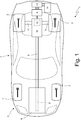
Figure 1 is a schematic plan view of a road vehicle provided with a hybrid drive system that is controlled in accordance with the control method of the present invention; -
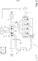
Figure 2 is a schematic view of the hybrid drive system ofFigure 1 ; -
Figure 3 is a diagram showing the characteristic torque curve and the characteristic power curve of an internal combustion heat engine of the hybrid drive system ofFigure 1 ; and -
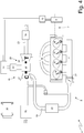
Figure 4 is a schematic view of one variant of the hybrid drive system ofFigure 1 . - In
Figure 1 , thenumeral 1 indicates, as a whole, a hybrid drive road vehicle equipped with twofront wheels 2 and tworear drive wheels 3, which receive the driving torque from a hybrid drive system 4. - The hybrid drive system 4 comprises an internal
combustion heat engine 5, which is arranged at the front, is provided with adrive shaft 6, and implements the Otto cycle using petrol or similar fuels as a fuel (typically LPG, methane, or ethanol or mixtures of petrol and ethanol). The hybrid drive system 4 also includes anautomatic transmission 7, which transmits the driving torque generated by theinternal combustion engine 5 to therear drive wheels 3. The hybrid drive system 4 also comprises anelectric machine 8, which is mechanically connected to thetransmission 7 and is reversible (i.e. it can work both as an electric motor by absorbing electric energy and generating a mechanical driving torque, and as an electric generator by absorbing mechanical energy and generating electric energy). - The
transmission 7 comprises atransmission shaft 9 which, on one side, is angularly integral with thedrive shaft 6 and, on the other side, is mechanically connected to a servo-assistedgearbox 10, which is arranged at the back and transmits the motion to therear drive wheels 3 by means of twoaxle shafts 11 that receive the motion from adifferential 12. Theelectric machine 8 is mechanically connected to the servo-assistedgearbox 10 and, for example, is angularly integral with a primary shaft of the servo-assistedgearbox 10. - The
electric machine 8 is controlled by an electronic control device 13 (in particular an electronic direct-alternating power converter, i.e. an inverter), which is electrically connected to an electricalenergy storage system 14 generally provided with chemical batteries. - As shown in
Figure 2 , the internalcombustion heat engine 5 is supercharged by aturbocharger supercharging system 15. In addition, the internalcombustion heat engine 5 comprises fourcylinders 16, each of which is connected to anintake manifold 17 via at least one respective intake valve (not shown) and to anexhaust manifold 18 via at least one respective exhaust valve (not shown); eachcylinder 16 houses, on the inside, a respective piston that slides with reciprocating motion and is mechanically connected to thedrive shaft 6. Theintake manifold 17 receives fresh air (i.e. air from the external environment) through anintake pipe 19, which is provided with anair filter 20 and is controlled by a throttle valve 21 (i.e. thethrottle valve 21 adjusts the flow rate of fresh air fed by theintake pipe 19 to the intake manifold 17). Anintercooler 22, whose function is to cool the intake air, is arranged along theintake pipe 19. Theexhaust manifold 18 is connected to anexhaust pipe 23 that feeds the exhaust gases produced by combustion to an exhaust system, which emits the gases produced by combustion into the atmosphere and normally comprises at least onecatalyst 24 and at least one silencer (not shown) arranged downstream of thecatalyst 24. - The
supercharging system 15 of the internalcombustion heat engine 5 comprises aturbocharger 25 provided with aturbine 26, which is arranged along theexhaust pipe 23 so as to rotate at high speed under the thrust of the exhaust gases expelled by thecylinders 16, and acompressor 27, which is arranged along theintake pipe 19 so as to increase the pressure of the air fed by thefeeding pipe 19. In addition, theturbocharger 25 comprises anelectric machine 28 that is mechanically connected to the shaft of the turbocharger 25 (i.e. is mechanically connected to theturbine 26 and the compressor 27) and is reversible (i.e. it can be operated as an electric motor to absorb electric energy and produce a mechanical torque or as a generator to absorb mechanical energy and produce electric energy). Theelectric machine 28 is electrically connected to an electronic control device 29 (in particular an electronic direct-alternating power converter, i.e. an inverter), which, in turn, is connected to the electricalenergy storage system 14. - The internal combustion heat engine involves the controlled ignition of the mixture, i.e. each
cylinder 16 is provided with at least one spark plug that is actuated to ignite the mixture inside thecylinder 16 itself. - In the embodiment illustrated in the attached figures, the
turbocharger 25 comprises a single shaft to which theturbine 26, thecompressor 27 and theelectric machine 28 are keyed (i.e. theturbine 26 andcompressor 27 are mutually mechanically constrained); according to a different embodiment, not shown, the turbocharger comprises a first shaft to which theturbine 26 and theelectric machine 28 are keyed, and a second shaft to which thecompressor 27 and a further electric machine are keyed (i.e. theturbine 26 andcompressor 27 are not mutually mechanically constrained and are therefore free to rotate at different rotational speeds). - As said above, the
drive shaft 6 of the internalcombustion heat engine 5 is connected to thetransmission 7, which transmits the driving torque generated by theinternal combustion engine 5 itself to therear driving wheels 3 and is provided with the reversibleelectric machine 8. - To summarize, the hybrid drive system 4 comprises three active components (i.e. able to generate mechanical power and/or electric power): the internal combustion heat engine 5 (only able to generate mechanical power) and the two
electric machines 8 and 28 (able to generate mechanical power, and alternatively electric power). - The hybrid drive system 4 is controlled by an
electronic control unit 30, which supervises the operation of the hybrid drive system 4 and therefore controls the internalcombustion heat engine 5 and the twoelectric machines - The operation of the hybrid drive system 4 is described below.
- The
electronic control unit 30 integrates a vehicle management unit (also referred to as VMU) which receives the commands given by the driver as input and accordingly establishes the target torque and speed of rotation of the internalcombustion heat engine 5 and of the twoelectric machines electronic control unit 30 receives the position of the controls on which the driver acts (accelerator pedal, brake pedal and shift controls), as input, to acquire the wishes expressed by the driver and then translates these wishes into a target longitudinal speed (with the direction, i.e. forwards or backwards) and a target longitudinal acceleration for theroad vehicle 1. Hence, theelectronic control unit 30 establishes how to pursue the target longitudinal speed and the target longitudinal acceleration by coordinating the action of the internalcombustion heat engine 5, thegearbox 10 and theelectric machines combustion heat engine 5, establishes a target transmission ratio (which can also comprise the neutral position) for thegearbox 10, and establishes target TTM1 and TTM2 torques (which can be positive by providing a motor operating mode, negative by providing a generator operating mode, or null, corresponding to the switching off of theelectric machines 8 and 28) and a target speed of rotation for each of theelectric machines - It is important to emphasize that the target speeds of rotation have a limited degree of freedom, as the speed of rotation of the internal
combustion heat engine 5 and the speed of rotation of theelectric machine 8 are substantially imposed by the speed of travel of the road vehicle 1 (obviously through the transmission ratio selected in the gearbox 10), whereas the speed of rotation of theelectric machine 8 is substantially imposed by the speed of the exhaust gases in theexhaust pipe 23. - In use, the
electronic control unit 30 establishes a target torque TT to be generated by the hybrid drive system 4 (and then transmitted to the drive wheels 3) and thus divides the target torque TT of the hybrid drive system 4 into a target torque TTE of the internalcombustion heat engine 5 and a target torque TTM1 of theelectric machine 8; obviously, the following equation must be obeyed:
electronic control unit 30 establishes a target torque TTE to be generated by the internalcombustion heat engine 5. - At the same time, the
electronic control unit 30 controls the internalcombustion heat engine 5 to pursue the corresponding target torque TTE and controls theelectric machine 8 to pursue the corresponding target torque TTM1. - In a first operating mode ("standard", as universally diffused in the control of internal combustion heat engines with controlled ignition of the mixture), the internal
combustion heat engine 5 is controlled to pursue the target torque TTE by varying the degree of opening of thethrottle valve 21 so as to adjust the flow rate of fresh air fed to thecylinders 16 in order to vary the drive torque generated by the internalcombustion heat engine 5; at the same time, a quantity of fuel that, based on a stoichiometric ratio, depends on the quantity of fresh air entering thecylinders 16, is fed into thecylinders 16 so that the combustion in thecylinders 16 always occurs under stoichiometric conditions. - In a second operating mode ("innovative", as never used before in internal combustion heat engines with controlled ignition of the mixture), the internal
combustion heat engine 5 is controlled to pursue the target torque TTE by completely opening thethrottle valve 21 and always keeping it completely open, operating theelectric machine 28 as an electric generator so as to absorb torque from theturbine 26, operating theelectric machine 8 as a motor so as to deliver torque to thedrive wheels 3, and varying the electric power generated by theelectric machine 28, so as to adjust the flow rate of fresh air fed to thecylinders 16 in order to vary the drive torque generated by the internalcombustion heat engine 5; at the same time, a quantity of fuel that, based on a stoichiometric ratio, depends on the quantity of fresh air entering thecylinders 16, is fed into thecylinders 16 so that the combustion in thecylinders 16 always occurs under stoichiometric conditions. - In other words, in the second operating mode, the combustion in the
cylinders 16 is always carried out under stoichiometric conditions and therefore the amount of fuel fed into thecylinders 16 is always established as a function of the amount of fresh air entering saidcylinders 16; however, the amount of fresh air entering the cylinders 16 (and therefore the driving torque generated by the combustion in the cylinders 16) is not adjusted by varying the degree of opening of the throttle valve 21 (i.e., "by throttling" the intake pipe 17), but instead is adjusted by varying the exhaust back-pressure generated by the turbine 26 (i.e., "by throttling" the exhaust pipe 23) via the electric power generated by theelectric machine 28. In fact, increasing the electric power generated by theelectric machine 28 increases the amount of energy removed by theturbine 26 from the exhaust gases in theexhaust pipe 23, consequently the exhaust back-pressure generated by theturbine 26 increases, and consequently the amount of fresh air entering thecylinders 16 decreases; similarly, decreasing the electric power generated by theelectric machine 28 decreases the amount of energy removed by theturbine 26 from the exhaust gases in theexhaust pipe 23, consequently the exhaust back-pressure generated by theturbine 26 decreases, and consequently the amount of fresh air entering thecylinders 16 increases. - Thus, in the second operating mode, the
throttle valve 21 is not used and is always kept in the maximum opening position to minimize load loss in theintake pipe 19 since the amount of fresh air entering thecylinders 16 is totally regulated by adjusting the electric power generated by the electric machine 28 (i.e. adjusting the exhaust back-pressure generated by the turbine 26). - In the second operating mode, the electric power absorbed by the
electric machine 8 is established based on the electric power generated by theelectric machine 28. In particular, in the second operating mode, theelectric machine 8 is controlled so as to absorb an electric power that is equal to the electric power generated by theelectric machine 28 minus the electric power absorbed by auxiliary services and minus/plus the electric power exchanged with the electricalenergy storage system 14. In other words, to avoid (if not for limited periods of time) an excess or a shortage of electric energy, theelectric machine 8 must absorb all and only the "available" electric power, i.e. all and only the electric power generated by theelectric machine 28 minus the electric power absorbed by auxiliary services; obviously, for short periods, a part of the electric power generated by theelectric machine 28 can be absorbed by thestorage system 14 or, for short periods, thestorage system 14 may transfer electric power (so as to always maintain the charge level of thestorage system 14 at an optimal value), but normally, for most of the time, thestorage system 14 is not operated and theelectric machine 8 absorbs all and only the electric power generated by theelectric machine 28 minus the electric power absorbed by auxiliary services. - The first operating mode can always be used, i.e. it can be used under all operating conditions of the hybrid drive system 4; instead, the second operating mode can only be used under certain operating conditions of the hybrid drive system 4, in particular when the total power requested of the hybrid drive system 4 exceeds a threshold TH1 for a length of time exceeding a second threshold TH2, i.e. when the total power requested of the drive system 4 is permanently higher than the threshold TH1; how to establish the threshold TH1 is described below, while the threshold TH2 can be, for example, between 4 and 20 seconds. In other words, the exhaust back-pressure generated by the
turbine 26 can be used effectively and efficiently to adjust the amount of fresh air entering thecylinders 16 only if a relatively high average flow rate of fresh air enters thecylinders 16 and if the speed of rotation is sufficiently high; moreover, the shift from the first operating mode to the second operating mode and vice versa requires a certain amount of time and is not convenient if performed too frequently. - From the characteristic driving torque curve (shown with a solid line in the graph of
Figure 3 ) and the characteristic power curve (shown with a dotted line in the graph ofFigure 3 ) of the internalcombustion heat engine 5, it can be seen that the speed of rotation of the internalcombustion heat engine 5 ranges from a minimum value ωmin to a maximum value ωmax and that the torque generated by the internalcombustion heat engine 5 initially increases as the speed of rotation increases, until a maximum value Tmax is reached at a speed of rotation ωTmax of the maximum torque, and decreases as the speed of rotation increases subsequent to the speed of rotation ωTmax of the maximum torque. The second operating mode is only possible when the actual rotational speed of the internalcombustion heat engine 5 is higher than the speed of rotation ωTmax of the maximum torque, i.e. only when the driving torque generated by the internalcombustion heat engine 5 is less than the maximum value Tmax and decreases as the speed of rotation increases; accordingly, the threshold TH1 must be (suitably) higher than the power value generated at the speed of rotation ωTmax of the maximum torque (the threshold TH1 cannot be too close to the power value generated at the speed of rotation ωTmax of the maximum torque to avoid operating too close to the speed of rotation ωTmax of the maximum torque) . - From the above, it appears that the hybrid drive system 4 is always started by using the first operating mode, and that the second operating mode is used instead of the first operating mode only under certain conditions (described above). From the point of view of the
road vehicle 1, the second operating mode is substantially used when theroad vehicle 1 is travelling on a motorway, i.e. when it travels long distances at high and approximately constant speed; in this respect, it is important to note that the decision to use the second operating mode can be taken not only considering the current operational status of the hybrid drive system 4, but also the path (determined by a cartographic GPS device on board the road vehicle 1) on which theroad vehicle 1 is located: if the cartographic GPS device reveals that theroad vehicle 1 has just entered a stretch of motorway (or similar), the second operating mode can be activated as soon as possible (i.e. restricting or cancelling the threshold TH2), whereas, if the cartographic GPS device reveals that theroad vehicle 1 is in urban areas, the second operating mode can be irrespectively disabled. - According to a preferred embodiment, in the second operating mode, the fast adjustment of the torque generated by the hybrid drive system 4 is carried out by varying the torque generated by the
electric machine 8, and the slow adjustment of the torque generated by the hybrid drive system 4 is carried out by varying the torque generated by the internalcombustion heat engine 5; in other words, when the target torque TT to be generated by the hybrid drive system 4 undergoes a variation, this variation is obtained by rapidly varying the target torque TTM1 of theelectric machine 8 and slowly varying the target torque TTE of the internalcombustion heat engine 5, i.e. by initially causing the variation to be absorbed entirely (obviously as far as possible) by the electric machine 8 (which responds much more quickly and can also be overloaded for short instants of time) and transferring the absorption of the variation more slowly from theelectric machine 8 to the internalcombustion heat engine 5. As a numerical example, let us suppose that under certain conditions the target torque TT to be generated by the hybrid drive system 4 is 70 Nm, that the target torque TTM1 of theelectric machine 8 is 15 Nm, that the target torque TTE of the internalcombustion heat engine 5 is 55 Nm; and that at a certain moment the target torque TT to be generated by the hybrid drive system 4 passes from 70 Nm to 80 Nm (for example to perform an overtaking manoeuvre or for the presence of a slope): the target torque TTM1 of theelectric machine 8 is immediately brought to 25 Nm (in less than a tenth of a second) and then is slowly lowered to 18 Nm (in a few seconds) while the target torque TTE of the internalcombustion heat engine 5 is slowly increased from 55 Nm to 62 Nm (in a few seconds). - By operating as described above (i.e. slowly varying the target torque TTE of the internal combustion heat engine 5), in the transitional phases, it may happen that the
electric machine 8 absorbs a different (greater or lesser) electric power than the electric power generated by theelectric machine 28; obviously, this difference is always compensated for by the electricalenergy storage system 14. - It is preferable to operate as described above (i.e. by slowly varying the target torque TTE of the internal combustion heat engine 5) because controlling the flow rate of fresh air fed to the
cylinders 16 by controlling the back-pressure of theturbine 26 is relatively slow and therefore would not be able to pursue without delay a target torque TTE of the internalcombustion heat engine 5 that varies too quickly. On the contrary, theelectric machine 8 is also capable of pursuing without delay a target torque TTM1 that varies very quickly (i.e. with significant variations of torque even within fractions of a second). - According to a preferred non-limiting embodiment, the ratio between the rated power of the internal
combustion heat engine 5 and the rated power of theelectric machine 28 is between 5 and 6, whereas the ratio between the rated power of the internalcombustion heat engine 5 and the rated power of theelectric machine 8 is between 3 and 4.5. By way of example, the rated power of the internalcombustion heat engine 5 may be approximately 110 kW, the rated power of theelectric machine 28 may be approximately 20 kW, and the rated power of theelectric machine 8 may be approximately 30 kW. - In the embodiment shown in
Figure 2 , the superchargingsystem 15 provides a pop-off valve (or a blow-off valve), which bypasses thecompressor 27 and is used to control and/or limit the maximum pressure exerted by thecompressor 27 itself. Moreover, in the embodiment shown inFigure 2 , the superchargingsystem 15 also provides a wastegate valve, which bypasses theturbine 26 to limit the maximum pressure upstream of theturbine 26. The wastegate valve is redundant and is provided solely as an emergency back-up (replacement), since the function of the wastegate valve is normally performed by theelectric machine 28 which always provides for limiting the maximum pressure upstream of theturbine 26. In fact, in the alternative embodiment shown inFigure 4 , the superchargingsystem 15 has no wastegate valve. - In the embodiment illustrated in the attached figures, the internal
combustion heat engine 5 has fourcylinders 16 arranged in-line; according to other, perfectly equivalent embodiments, not shown, the internalcombustion heat engine 5 has a different number ofcylinders 16 and/or exhibits a different arrangement of thecylinders 16. - The embodiments described herein may be combined with each other without departing from the scope of protection of the present invention.
- The above-described method of controlling the hybrid drive system 4 has numerous advantages.
- Firstly, the above-described method of controlling the hybrid drive system 4 allows, when the second operating mode is used, very high energy efficiency values (close to, if not even higher than, 50%) even when an internal
combustion heat engine 5 fuelled by petrol (or similar fuels) is used. - In addition, the above-described control method allows the internal
combustion heat engine 5 to be controlled in a simple and effective way even in the second operating mode. - Lastly, the above-described method of control of the hybrid drive system 4, even in the second operating mode, does not subject the internal
combustion heat engine 5 to stress and/or higher-than-normal wear. -
- 1
- vehicle
- 2
- front wheels
- 3
- rear wheels
- 4
- drive system
- 5
- heat engine
- 6
- drive shaft
- 7
- transmission
- 8
- main electric machine
- 9
- transmission shaft
- 10
- manual gearbox
- 11
- axle shafts
- 12
- differential
- 13
- electronic control device
- 14
- storage system
- 15
- supercharging system
- 16
- cylinders
- 17
- intake manifold
- 18
- exhaust manifold
- 19
- intake pipe
- 20
- air filter
- 21
- throttle valve
- 22
- intercooler
- 23
- exhaust pipe
- 24
- catalyst
- 25
- turbocharger
- 26
- turbine
- 27
- compressor
- 28
- electric machine
- 29
- control device
- 30
- electronic control unit
Claims (13)
- A method to control a hybrid drive system (4) for a road vehicle (1) comprising at least a pair of drive wheels (3) ;
the hybrid drive system (4) comprises:an internal combustion heat engine (5), which is designed to transmit the motion to the drive wheels (3) and comprises at least one cylinder (16), an intake manifold (17), which is connected to the cylinder (16) through at least one intake valve, an exhaust manifold (18), which is connected to the cylinder (16) through at least one exhaust valve, an intake pipe (19), which feeds fresh air to the intake manifold (17), a throttle valve (21), which adjusts the flow rate of fresh air fed by the intake pipe (19) to the intake manifold (17), an exhaust pipe (23), which is connected to the exhaust manifold (18), and a turbocharger (25), which is provided with a turbine (26) arranged along the exhaust pipe (23) so as to rotate under the thrust of the exhaust gases expelled by the cylinder (16), and with a compressor (27) arranged along the intake pipe (19) so as to increase the pressure of the air fed by the intake pipe (19) ;a first electric machine (8), which is able to transmit the motion to the drive wheels (3) and is controlled by a first electronic control device (13) electrically connected to an electrical energy storage system (14); anda second electric machine (28), which is mechanically connected to the turbine (26) of the turbocharger (25) and is controlled by a second electronic control device (29) electrically connected to the electrical energy storage system (14);the control method comprises the steps of:establishing a target torque (TTE) to be generated by the internal combustion heat engine (5); andcontrolling the internal combustion heat engine (5) so as to pursue the target torque (TTE);wherein, in a first operating mode, the step of controlling the internal combustion heat engine (5) so as to pursue the target torque (TTE) comprises the further steps of:varying the degree of opening of the throttle valve (21) so as to adjust the flow rate of fresh air fed to the cylinder (16) in order to vary the torque generated by the internal combustion heat engine (5); andfeeding into the cylinder (16) a quantity of fuel that, based on a stoichiometric ratio, depends on the quantity of fresh air entering the cylinder (16);the control method is characterized in that, in a second operating mode, the step of controlling the internal combustion heat engine (5) so as to pursue the target torque (TTE) comprises the further steps of:completely opening the throttle valve (21) and always keeping it completely open;operating the second electric machine (28) as an electric generator so as to absorb torque from the turbine (26);operating the first electric machine (8) as a motor so as to deliver torque to the drive wheels (3);varying the electric power generated by the second electric machine (28) so as to adjust the flow rate of fresh air fed to the cylinder (16) in order to vary the torque generated by the internal combustion heat engine (5); andfeeding into the cylinder (16) a quantity of fuel that, based on a stoichiometric ratio, depends on the quantity of fresh air entering the cylinder (16). - The control method according to claim 1, wherein, in the second operating mode, the electric power absorbed by the first electric machine (8) is established based on the electric power generated by the second electric machine (28) .
- The control method according to claim 2, wherein, in the second operating mode, the first electric machine (8) is controlled so as to absorb an electric power that is equal to the electric power generated by the second electric machine (28) minus the electric power absorbed by auxiliary services and minus/plus the electric power exchanged with the electrical energy storage system (14).
- The control method according to claim 1, 2 or 3, wherein the second operating mode is used when the total power requested of the hybrid drive system (4) exceeds a first threshold (TH1).
- The control method according to claim 4, wherein the second operating mode is used when the total power requested of the hybrid drive system (4) exceeds the first threshold (TH1) for an amount of time exceeding a second threshold (TH2).
- The control method according to any of the claims from 1 to 5, wherein, in the second operating mode, the electric power generated by the second electric machine (28) is increased in order to decrease the flow rate of fresh air fed to the cylinder (16) and, hence, decrease the torque generated by the internal combustion heat engine (5) and vice versa.
- The control method according to any of the claims from 1 to 6, wherein the hybrid drive system (4) is always started by using the first operating mode.
- The control method according to claim 7, wherein the second operating mode is used instead of the first operating mode only in given conditions.
- The control method according to any of the claims from 1 to 8, wherein the second operating mode is used when the road vehicle (1) is driving on a highway.
- The control method according to any of the claims from 1 to 9, wherein, in the second operating mode, the fast adjustment of the torque generated by the hybrid drive system (4) is carried out by varying the torque generated by the first electric machine (8), and the slow adjustment of the torque generated by the hybrid drive system (4) is carried out by varying the torque generated by the internal combustion heat engine (5).
- The control method according to claim 10 and comprising, in the second operating mode, the further steps of:establishing a target torque (TT) to be generated by the hybrid drive system (4);dividing the target torque (TT) of the hybrid drive system (4) into a target torque (TTE) of the internal combustion heat engine (5) and a target torque (TTM1) of the first electric machine (8); andin case of change of the target torque of the hybrid drive system (4), varying the target torque (TTM1) of the first electric machine (8) faster and varying the target torque (TTE) of the internal combustion heat engine (5) slower.
- The control method according to any of the claims from 1 to 11, wherein:the speed of rotation of the internal combustion heat engine (5) ranges from a minimum value (ωmin) to a maximum value (ωmax) ;the torque generated by the internal combustion heat engine (5) initially increases as the speed of rotation increases, until a maximum value (Tmax) is reached at a speed of rotation (ωTmax) of the maximum torque, and decreases as the speed of rotation increases subsequent to the speed of rotation (ωTmax) of the maximum torque; andthe second operating mode is used only when the actual speed of rotation of the internal combustion heat engine (5) is greater than the speed of rotation (ωTmax) of the maximum torque.
- The control method according to any of the claims from 1 to 12, wherein the internal combustion heat engine (5) implements the Otto cycle and involves the controlled ignition of the mixture in the cylinder (16).
Applications Claiming Priority (1)
| Application Number | Priority Date | Filing Date | Title |
|---|---|---|---|
| IT102017000047852A IT201700047852A1 (en) | 2017-05-04 | 2017-05-04 | METHOD OF CONTROL OF A HYBRID PROPULSION SYSTEM FOR A ROAD VEHICLE |
Publications (2)
| Publication Number | Publication Date |
|---|---|
| EP3399173A1 true EP3399173A1 (en) | 2018-11-07 |
| EP3399173B1 EP3399173B1 (en) | 2024-02-21 |
Family
ID=59811946
Family Applications (1)
| Application Number | Title | Priority Date | Filing Date |
|---|---|---|---|
| EP18170931.2A Active EP3399173B1 (en) | 2017-05-04 | 2018-05-04 | Method to control a hybrid drive system for a road vehicle |
Country Status (4)
| Country | Link |
|---|---|
| US (1) | US10988134B2 (en) |
| EP (1) | EP3399173B1 (en) |
| CN (1) | CN108791323B (en) |
| IT (1) | IT201700047852A1 (en) |
Cited By (1)
| Publication number | Priority date | Publication date | Assignee | Title |
|---|---|---|---|---|
| CN119712327A (en) * | 2024-12-06 | 2025-03-28 | 广西大学 | Intelligent control system of miniature turbocharged engine |
Families Citing this family (3)
| Publication number | Priority date | Publication date | Assignee | Title |
|---|---|---|---|---|
| GB201718253D0 (en) | 2017-11-03 | 2017-12-20 | Univ Oxford Innovation Ltd | Energy recovery system, vehicle, and method of recovering energy |
| IT201900018362A1 (en) * | 2019-10-10 | 2021-04-10 | Texa Spa | METHOD AND CONTROL SYSTEM FOR AT LEAST TWO ELECTRIC TRACTION MOTORS OF A VEHICLE |
| US11958472B2 (en) * | 2020-02-20 | 2024-04-16 | Schaeffler Technologies AG & Co. KG | Method for controlling a hybrid drive train |
Citations (5)
| Publication number | Priority date | Publication date | Assignee | Title |
|---|---|---|---|---|
| US20100107632A1 (en) * | 2008-11-04 | 2010-05-06 | Gm Global Technology Operations, Inc. | Hybrid powertrain and method for controlling a hybrid powertrain |
| DE102012105069A1 (en) * | 2011-07-04 | 2013-01-10 | Avl List Gmbh | Hybrid vehicle, has compressor driven by electric machine that is operated as generator in operating range or partial loading range of combustion engine, and another electric machine connected with crankshaft of engine |
| WO2014165233A1 (en) | 2013-03-12 | 2014-10-09 | Eaton Corporation | Adaptive state of charge regulation and control of variable speed hybrid electric supercharger assembly for efficient vehicle operation |
| DE202014105279U1 (en) * | 2014-10-21 | 2014-11-28 | Ford Global Technologies, Llc | Twin turbo system with electrically driven compressors |
| EP3088124A1 (en) | 2015-04-16 | 2016-11-02 | Magneti Marelli S.p.A. | Method of laser welding two adjacent metal elements of a stator winding with rigid bars for an electric machine |
Family Cites Families (15)
| Publication number | Priority date | Publication date | Assignee | Title |
|---|---|---|---|---|
| ITBO20030256A1 (en) * | 2003-04-30 | 2004-11-01 | Magneti Marelli Powertrain Spa | CONTROL SYSTEM WITH MULTIPROCESSOR ARCHITECTURE FOR |
| US7076954B1 (en) * | 2005-03-31 | 2006-07-18 | Caterpillar Inc. | Turbocharger system |
| ITBO20070605A1 (en) * | 2007-09-05 | 2009-03-06 | Enea Ente Nuove Tec | METHOD OF CONTROL OF A HYBRID VEHICLE DURING A REGENERATIVE DECELERATION |
| EP2055601A1 (en) * | 2007-10-29 | 2009-05-06 | MAGNETI MARELLI POWERTRAIN S.p.A. | Control method for limiting the performances of a road vehicle |
| US20100050987A1 (en) * | 2008-09-04 | 2010-03-04 | Toyota Jidosha Kabushiki Kaisha | Internal combustion engine control device |
| GB2495755A (en) * | 2011-10-20 | 2013-04-24 | Gm Global Tech Operations Inc | Correction of fuel injection timings in an internal combustion engine |
| CN103847492B (en) | 2012-11-29 | 2017-07-25 | 上海汽车集团股份有限公司 | Hybrid system, method and vehicle based on dual-mode homogeneous compression ignition internal combustion engine |
| JP6412018B2 (en) * | 2013-02-15 | 2018-10-24 | ウォン,アレクサンダー | Turbo charger |
| JP6272077B2 (en) * | 2014-02-25 | 2018-01-31 | 三菱重工業株式会社 | Turbocharger and ship |
| US9527499B2 (en) | 2014-07-17 | 2016-12-27 | GM Global Technology Operations LLC | Power-split hybrid powertrain using turbine generator |
| GB201414761D0 (en) * | 2014-08-20 | 2014-10-01 | Jaguar Land Rover Ltd | Vehicle noise suppression method |
| DE102014221333B4 (en) | 2014-10-21 | 2022-07-07 | Ford Global Technologies, Llc | Twin turbo system with electrically driven compressors |
| US9629189B2 (en) * | 2014-11-17 | 2017-04-18 | GM Global Technology Operations LLC | System and method for enabling a user to adjust the operation of a powertrain in a vehicle, to adjust the appearance of a user interface device in the vehicle, and/or to adjust vehicle noise |
| DE102016011069B4 (en) * | 2016-09-14 | 2020-02-27 | Audi Ag | Method for operating a drive device and corresponding drive device |
| IT201600105858A1 (en) * | 2016-10-20 | 2018-04-20 | Magneti Marelli Spa | ELECTRIC SYSTEM PROVIDED WITH A DUAL VOLTAGE ACCUMULATION ASSEMBLY FOR A VEHICLE |
-
2017
- 2017-05-04 IT IT102017000047852A patent/IT201700047852A1/en unknown
-
2018
- 2018-05-02 US US15/969,324 patent/US10988134B2/en active Active
- 2018-05-04 EP EP18170931.2A patent/EP3399173B1/en active Active
- 2018-05-04 CN CN201810422161.8A patent/CN108791323B/en active Active
Patent Citations (5)
| Publication number | Priority date | Publication date | Assignee | Title |
|---|---|---|---|---|
| US20100107632A1 (en) * | 2008-11-04 | 2010-05-06 | Gm Global Technology Operations, Inc. | Hybrid powertrain and method for controlling a hybrid powertrain |
| DE102012105069A1 (en) * | 2011-07-04 | 2013-01-10 | Avl List Gmbh | Hybrid vehicle, has compressor driven by electric machine that is operated as generator in operating range or partial loading range of combustion engine, and another electric machine connected with crankshaft of engine |
| WO2014165233A1 (en) | 2013-03-12 | 2014-10-09 | Eaton Corporation | Adaptive state of charge regulation and control of variable speed hybrid electric supercharger assembly for efficient vehicle operation |
| DE202014105279U1 (en) * | 2014-10-21 | 2014-11-28 | Ford Global Technologies, Llc | Twin turbo system with electrically driven compressors |
| EP3088124A1 (en) | 2015-04-16 | 2016-11-02 | Magneti Marelli S.p.A. | Method of laser welding two adjacent metal elements of a stator winding with rigid bars for an electric machine |
Cited By (1)
| Publication number | Priority date | Publication date | Assignee | Title |
|---|---|---|---|---|
| CN119712327A (en) * | 2024-12-06 | 2025-03-28 | 广西大学 | Intelligent control system of miniature turbocharged engine |
Also Published As
| Publication number | Publication date |
|---|---|
| CN108791323A (en) | 2018-11-13 |
| IT201700047852A1 (en) | 2018-11-04 |
| US20180319390A1 (en) | 2018-11-08 |
| EP3399173B1 (en) | 2024-02-21 |
| US10988134B2 (en) | 2021-04-27 |
| CN108791323B (en) | 2021-07-20 |
Similar Documents
| Publication | Publication Date | Title |
|---|---|---|
| EP2729684B1 (en) | Hybrid system comprising a supercharging system | |
| JP3449239B2 (en) | Control device for hybrid vehicle | |
| US7448981B2 (en) | Power output apparatus, vehicle equipped with power output apparatus, and control method of power output apparatus | |
| EP2971640B1 (en) | Adaptive state of charge regulation and control of variable speed hybrid electric supercharger assembly for efficient vehicle operation | |
| EP3399173B1 (en) | Method to control a hybrid drive system for a road vehicle | |
| US6350217B1 (en) | Method for establishing a defined active relationship between the operation of the accelerator pedal and the resulting braking torque of a vehicle | |
| US9789756B2 (en) | Hybrid vehicle with power boost | |
| CN101746373B (en) | Apparatus and method for controlling a hybrid vehicle | |
| CN104828091A (en) | Method, device and system of compensating torque of turbocharged engine | |
| WO2017111086A1 (en) | Engine control device | |
| CN103452683A (en) | Control device, control method, and control system for hybrid vehicle | |
| US7229381B2 (en) | Method for controlling engine starts for a vehicle powertrain | |
| JP2016117451A (en) | Vehicle control device | |
| US20210031746A1 (en) | Control device for hybrid vehicle | |
| CN111075587A (en) | Method and system for controlling engine torque reserve | |
| JP2011051542A (en) | Control device for hybrid vehicle | |
| US11352943B2 (en) | Control device for hybrid vehicle | |
| CN111911294A (en) | Four-wheel drive hybrid vehicle comprising an internal combustion heat engine of an electric turbine and corresponding control method | |
| JP2011201414A (en) | Vehicle drive controller | |
| JP2009149195A (en) | Control device for hybrid system | |
| CN1945061A (en) | Vehicular transmission | |
| CN111720223B (en) | Hybrid vehicle and method of braking a hybrid vehicle | |
| JP6031769B2 (en) | Regenerative control device | |
| JP2010275955A (en) | Vehicle control device | |
| Xiangyang et al. | Engine-start control strategy of P2 parallel hybrid electric vehicle |
Legal Events
| Date | Code | Title | Description |
|---|---|---|---|
| PUAI | Public reference made under article 153(3) epc to a published international application that has entered the european phase |
Free format text: ORIGINAL CODE: 0009012 |
|
| STAA | Information on the status of an ep patent application or granted ep patent |
Free format text: STATUS: THE APPLICATION HAS BEEN PUBLISHED |
|
| AK | Designated contracting states |
Kind code of ref document: A1 Designated state(s): AL AT BE BG CH CY CZ DE DK EE ES FI FR GB GR HR HU IE IS IT LI LT LU LV MC MK MT NL NO PL PT RO RS SE SI SK SM TR |
|
| AX | Request for extension of the european patent |
Extension state: BA ME |
|
| STAA | Information on the status of an ep patent application or granted ep patent |
Free format text: STATUS: REQUEST FOR EXAMINATION WAS MADE |
|
| 17P | Request for examination filed |
Effective date: 20190506 |
|
| STAA | Information on the status of an ep patent application or granted ep patent |
Free format text: STATUS: EXAMINATION IS IN PROGRESS |
|
| 17Q | First examination report despatched |
Effective date: 20211119 |
|
| RAP3 | Party data changed (applicant data changed or rights of an application transferred) |
Owner name: MARELLI EUROPE S.P.A. |
|
| RIC1 | Information provided on ipc code assigned before grant |
Ipc: F02B 41/10 20060101ALI20230801BHEP Ipc: F02B 39/12 20060101ALI20230801BHEP Ipc: F02B 39/10 20060101ALI20230801BHEP Ipc: F02D 41/00 20060101AFI20230801BHEP |
|
| GRAP | Despatch of communication of intention to grant a patent |
Free format text: ORIGINAL CODE: EPIDOSNIGR1 |
|
| STAA | Information on the status of an ep patent application or granted ep patent |
Free format text: STATUS: GRANT OF PATENT IS INTENDED |
|
| INTG | Intention to grant announced |
Effective date: 20230913 |
|
| GRAS | Grant fee paid |
Free format text: ORIGINAL CODE: EPIDOSNIGR3 |
|
| GRAA | (expected) grant |
Free format text: ORIGINAL CODE: 0009210 |
|
| STAA | Information on the status of an ep patent application or granted ep patent |
Free format text: STATUS: THE PATENT HAS BEEN GRANTED |
|
| AK | Designated contracting states |
Kind code of ref document: B1 Designated state(s): AL AT BE BG CH CY CZ DE DK EE ES FI FR GB GR HR HU IE IS IT LI LT LU LV MC MK MT NL NO PL PT RO RS SE SI SK SM TR |
|
| P01 | Opt-out of the competence of the unified patent court (upc) registered |
Effective date: 20240112 |
|
| REG | Reference to a national code |
Ref country code: GB Ref legal event code: FG4D |
|
| REG | Reference to a national code |
Ref country code: CH Ref legal event code: EP |
|
| REG | Reference to a national code |
Ref country code: DE Ref legal event code: R096 Ref document number: 602018065437 Country of ref document: DE |
|
| REG | Reference to a national code |
Ref country code: IE Ref legal event code: FG4D |
|
| REG | Reference to a national code |
Ref country code: LT Ref legal event code: MG9D |
|
| REG | Reference to a national code |
Ref country code: NL Ref legal event code: MP Effective date: 20240221 |
|
| PG25 | Lapsed in a contracting state [announced via postgrant information from national office to epo] |
Ref country code: IS Free format text: LAPSE BECAUSE OF FAILURE TO SUBMIT A TRANSLATION OF THE DESCRIPTION OR TO PAY THE FEE WITHIN THE PRESCRIBED TIME-LIMIT Effective date: 20240621 |
|
| PG25 | Lapsed in a contracting state [announced via postgrant information from national office to epo] |
Ref country code: LT Free format text: LAPSE BECAUSE OF FAILURE TO SUBMIT A TRANSLATION OF THE DESCRIPTION OR TO PAY THE FEE WITHIN THE PRESCRIBED TIME-LIMIT Effective date: 20240221 |
|
| PG25 | Lapsed in a contracting state [announced via postgrant information from national office to epo] |
Ref country code: GR Free format text: LAPSE BECAUSE OF FAILURE TO SUBMIT A TRANSLATION OF THE DESCRIPTION OR TO PAY THE FEE WITHIN THE PRESCRIBED TIME-LIMIT Effective date: 20240522 |
|
| REG | Reference to a national code |
Ref country code: AT Ref legal event code: MK05 Ref document number: 1659313 Country of ref document: AT Kind code of ref document: T Effective date: 20240221 |
|
| PG25 | Lapsed in a contracting state [announced via postgrant information from national office to epo] |
Ref country code: HR Free format text: LAPSE BECAUSE OF FAILURE TO SUBMIT A TRANSLATION OF THE DESCRIPTION OR TO PAY THE FEE WITHIN THE PRESCRIBED TIME-LIMIT Effective date: 20240221 Ref country code: NL Free format text: LAPSE BECAUSE OF FAILURE TO SUBMIT A TRANSLATION OF THE DESCRIPTION OR TO PAY THE FEE WITHIN THE PRESCRIBED TIME-LIMIT Effective date: 20240221 Ref country code: RS Free format text: LAPSE BECAUSE OF FAILURE TO SUBMIT A TRANSLATION OF THE DESCRIPTION OR TO PAY THE FEE WITHIN THE PRESCRIBED TIME-LIMIT Effective date: 20240521 |
|
| PG25 | Lapsed in a contracting state [announced via postgrant information from national office to epo] |
Ref country code: ES Free format text: LAPSE BECAUSE OF FAILURE TO SUBMIT A TRANSLATION OF THE DESCRIPTION OR TO PAY THE FEE WITHIN THE PRESCRIBED TIME-LIMIT Effective date: 20240221 |
|
| PG25 | Lapsed in a contracting state [announced via postgrant information from national office to epo] |
Ref country code: AT Free format text: LAPSE BECAUSE OF FAILURE TO SUBMIT A TRANSLATION OF THE DESCRIPTION OR TO PAY THE FEE WITHIN THE PRESCRIBED TIME-LIMIT Effective date: 20240221 |
|
| PG25 | Lapsed in a contracting state [announced via postgrant information from national office to epo] |
Ref country code: RS Free format text: LAPSE BECAUSE OF FAILURE TO SUBMIT A TRANSLATION OF THE DESCRIPTION OR TO PAY THE FEE WITHIN THE PRESCRIBED TIME-LIMIT Effective date: 20240521 Ref country code: NO Free format text: LAPSE BECAUSE OF FAILURE TO SUBMIT A TRANSLATION OF THE DESCRIPTION OR TO PAY THE FEE WITHIN THE PRESCRIBED TIME-LIMIT Effective date: 20240521 Ref country code: NL Free format text: LAPSE BECAUSE OF FAILURE TO SUBMIT A TRANSLATION OF THE DESCRIPTION OR TO PAY THE FEE WITHIN THE PRESCRIBED TIME-LIMIT Effective date: 20240221 Ref country code: LT Free format text: LAPSE BECAUSE OF FAILURE TO SUBMIT A TRANSLATION OF THE DESCRIPTION OR TO PAY THE FEE WITHIN THE PRESCRIBED TIME-LIMIT Effective date: 20240221 Ref country code: IS Free format text: LAPSE BECAUSE OF FAILURE TO SUBMIT A TRANSLATION OF THE DESCRIPTION OR TO PAY THE FEE WITHIN THE PRESCRIBED TIME-LIMIT Effective date: 20240621 Ref country code: HR Free format text: LAPSE BECAUSE OF FAILURE TO SUBMIT A TRANSLATION OF THE DESCRIPTION OR TO PAY THE FEE WITHIN THE PRESCRIBED TIME-LIMIT Effective date: 20240221 Ref country code: GR Free format text: LAPSE BECAUSE OF FAILURE TO SUBMIT A TRANSLATION OF THE DESCRIPTION OR TO PAY THE FEE WITHIN THE PRESCRIBED TIME-LIMIT Effective date: 20240522 Ref country code: FI Free format text: LAPSE BECAUSE OF FAILURE TO SUBMIT A TRANSLATION OF THE DESCRIPTION OR TO PAY THE FEE WITHIN THE PRESCRIBED TIME-LIMIT Effective date: 20240221 Ref country code: ES Free format text: LAPSE BECAUSE OF FAILURE TO SUBMIT A TRANSLATION OF THE DESCRIPTION OR TO PAY THE FEE WITHIN THE PRESCRIBED TIME-LIMIT Effective date: 20240221 Ref country code: BG Free format text: LAPSE BECAUSE OF FAILURE TO SUBMIT A TRANSLATION OF THE DESCRIPTION OR TO PAY THE FEE WITHIN THE PRESCRIBED TIME-LIMIT Effective date: 20240221 Ref country code: AT Free format text: LAPSE BECAUSE OF FAILURE TO SUBMIT A TRANSLATION OF THE DESCRIPTION OR TO PAY THE FEE WITHIN THE PRESCRIBED TIME-LIMIT Effective date: 20240221 |
|
| PG25 | Lapsed in a contracting state [announced via postgrant information from national office to epo] |
Ref country code: PL Free format text: LAPSE BECAUSE OF FAILURE TO SUBMIT A TRANSLATION OF THE DESCRIPTION OR TO PAY THE FEE WITHIN THE PRESCRIBED TIME-LIMIT Effective date: 20240221 Ref country code: PT Free format text: LAPSE BECAUSE OF FAILURE TO SUBMIT A TRANSLATION OF THE DESCRIPTION OR TO PAY THE FEE WITHIN THE PRESCRIBED TIME-LIMIT Effective date: 20240621 |
|
| PG25 | Lapsed in a contracting state [announced via postgrant information from national office to epo] |
Ref country code: SE Free format text: LAPSE BECAUSE OF FAILURE TO SUBMIT A TRANSLATION OF THE DESCRIPTION OR TO PAY THE FEE WITHIN THE PRESCRIBED TIME-LIMIT Effective date: 20240221 Ref country code: PT Free format text: LAPSE BECAUSE OF FAILURE TO SUBMIT A TRANSLATION OF THE DESCRIPTION OR TO PAY THE FEE WITHIN THE PRESCRIBED TIME-LIMIT Effective date: 20240621 Ref country code: PL Free format text: LAPSE BECAUSE OF FAILURE TO SUBMIT A TRANSLATION OF THE DESCRIPTION OR TO PAY THE FEE WITHIN THE PRESCRIBED TIME-LIMIT Effective date: 20240221 Ref country code: LV Free format text: LAPSE BECAUSE OF FAILURE TO SUBMIT A TRANSLATION OF THE DESCRIPTION OR TO PAY THE FEE WITHIN THE PRESCRIBED TIME-LIMIT Effective date: 20240221 |
|
| PG25 | Lapsed in a contracting state [announced via postgrant information from national office to epo] |
Ref country code: DK Free format text: LAPSE BECAUSE OF FAILURE TO SUBMIT A TRANSLATION OF THE DESCRIPTION OR TO PAY THE FEE WITHIN THE PRESCRIBED TIME-LIMIT Effective date: 20240221 |
|
| PG25 | Lapsed in a contracting state [announced via postgrant information from national office to epo] |
Ref country code: SM Free format text: LAPSE BECAUSE OF FAILURE TO SUBMIT A TRANSLATION OF THE DESCRIPTION OR TO PAY THE FEE WITHIN THE PRESCRIBED TIME-LIMIT Effective date: 20240221 |
|
| PG25 | Lapsed in a contracting state [announced via postgrant information from national office to epo] |
Ref country code: CZ Free format text: LAPSE BECAUSE OF FAILURE TO SUBMIT A TRANSLATION OF THE DESCRIPTION OR TO PAY THE FEE WITHIN THE PRESCRIBED TIME-LIMIT Effective date: 20240221 Ref country code: EE Free format text: LAPSE BECAUSE OF FAILURE TO SUBMIT A TRANSLATION OF THE DESCRIPTION OR TO PAY THE FEE WITHIN THE PRESCRIBED TIME-LIMIT Effective date: 20240221 |
|
| PG25 | Lapsed in a contracting state [announced via postgrant information from national office to epo] |
Ref country code: SK Free format text: LAPSE BECAUSE OF FAILURE TO SUBMIT A TRANSLATION OF THE DESCRIPTION OR TO PAY THE FEE WITHIN THE PRESCRIBED TIME-LIMIT Effective date: 20240221 |
|
| PG25 | Lapsed in a contracting state [announced via postgrant information from national office to epo] |
Ref country code: SM Free format text: LAPSE BECAUSE OF FAILURE TO SUBMIT A TRANSLATION OF THE DESCRIPTION OR TO PAY THE FEE WITHIN THE PRESCRIBED TIME-LIMIT Effective date: 20240221 Ref country code: SK Free format text: LAPSE BECAUSE OF FAILURE TO SUBMIT A TRANSLATION OF THE DESCRIPTION OR TO PAY THE FEE WITHIN THE PRESCRIBED TIME-LIMIT Effective date: 20240221 Ref country code: RO Free format text: LAPSE BECAUSE OF FAILURE TO SUBMIT A TRANSLATION OF THE DESCRIPTION OR TO PAY THE FEE WITHIN THE PRESCRIBED TIME-LIMIT Effective date: 20240221 Ref country code: EE Free format text: LAPSE BECAUSE OF FAILURE TO SUBMIT A TRANSLATION OF THE DESCRIPTION OR TO PAY THE FEE WITHIN THE PRESCRIBED TIME-LIMIT Effective date: 20240221 Ref country code: DK Free format text: LAPSE BECAUSE OF FAILURE TO SUBMIT A TRANSLATION OF THE DESCRIPTION OR TO PAY THE FEE WITHIN THE PRESCRIBED TIME-LIMIT Effective date: 20240221 Ref country code: CZ Free format text: LAPSE BECAUSE OF FAILURE TO SUBMIT A TRANSLATION OF THE DESCRIPTION OR TO PAY THE FEE WITHIN THE PRESCRIBED TIME-LIMIT Effective date: 20240221 |
|
| REG | Reference to a national code |
Ref country code: DE Ref legal event code: R097 Ref document number: 602018065437 Country of ref document: DE |
|
| PLBE | No opposition filed within time limit |
Free format text: ORIGINAL CODE: 0009261 |
|
| STAA | Information on the status of an ep patent application or granted ep patent |
Free format text: STATUS: NO OPPOSITION FILED WITHIN TIME LIMIT |
|
| REG | Reference to a national code |
Ref country code: CH Ref legal event code: PL |
|
| PG25 | Lapsed in a contracting state [announced via postgrant information from national office to epo] |
Ref country code: MC Free format text: LAPSE BECAUSE OF FAILURE TO SUBMIT A TRANSLATION OF THE DESCRIPTION OR TO PAY THE FEE WITHIN THE PRESCRIBED TIME-LIMIT Effective date: 20240221 |
|
| PG25 | Lapsed in a contracting state [announced via postgrant information from national office to epo] |
Ref country code: LU Free format text: LAPSE BECAUSE OF NON-PAYMENT OF DUE FEES Effective date: 20240504 |
|
| 26N | No opposition filed |
Effective date: 20241122 |
|
| GBPC | Gb: european patent ceased through non-payment of renewal fee |
Effective date: 20240521 |
|
| PG25 | Lapsed in a contracting state [announced via postgrant information from national office to epo] |
Ref country code: MC Free format text: LAPSE BECAUSE OF FAILURE TO SUBMIT A TRANSLATION OF THE DESCRIPTION OR TO PAY THE FEE WITHIN THE PRESCRIBED TIME-LIMIT Effective date: 20240221 Ref country code: LU Free format text: LAPSE BECAUSE OF NON-PAYMENT OF DUE FEES Effective date: 20240504 Ref country code: CH Free format text: LAPSE BECAUSE OF NON-PAYMENT OF DUE FEES Effective date: 20240531 |
|
| REG | Reference to a national code |
Ref country code: BE Ref legal event code: MM Effective date: 20240531 |
|
| PG25 | Lapsed in a contracting state [announced via postgrant information from national office to epo] |
Ref country code: IE Free format text: LAPSE BECAUSE OF NON-PAYMENT OF DUE FEES Effective date: 20240504 |
|
| PG25 | Lapsed in a contracting state [announced via postgrant information from national office to epo] |
Ref country code: BE Free format text: LAPSE BECAUSE OF NON-PAYMENT OF DUE FEES Effective date: 20240531 Ref country code: SI Free format text: LAPSE BECAUSE OF FAILURE TO SUBMIT A TRANSLATION OF THE DESCRIPTION OR TO PAY THE FEE WITHIN THE PRESCRIBED TIME-LIMIT Effective date: 20240221 |
|
| PG25 | Lapsed in a contracting state [announced via postgrant information from national office to epo] |
Ref country code: GB Free format text: LAPSE BECAUSE OF NON-PAYMENT OF DUE FEES Effective date: 20240521 |
|
| PGFP | Annual fee paid to national office [announced via postgrant information from national office to epo] |
Ref country code: DE Payment date: 20250423 Year of fee payment: 8 |
|
| PGFP | Annual fee paid to national office [announced via postgrant information from national office to epo] |
Ref country code: IT Payment date: 20250423 Year of fee payment: 8 |
|
| PGFP | Annual fee paid to national office [announced via postgrant information from national office to epo] |
Ref country code: FR Payment date: 20250423 Year of fee payment: 8 |
|
| PG25 | Lapsed in a contracting state [announced via postgrant information from national office to epo] |
Ref country code: CY Free format text: LAPSE BECAUSE OF FAILURE TO SUBMIT A TRANSLATION OF THE DESCRIPTION OR TO PAY THE FEE WITHIN THE PRESCRIBED TIME-LIMIT; INVALID AB INITIO Effective date: 20180504 |
|
| PG25 | Lapsed in a contracting state [announced via postgrant information from national office to epo] |
Ref country code: HU Free format text: LAPSE BECAUSE OF FAILURE TO SUBMIT A TRANSLATION OF THE DESCRIPTION OR TO PAY THE FEE WITHIN THE PRESCRIBED TIME-LIMIT; INVALID AB INITIO Effective date: 20180504 |