EP3088124A1 - Method of laser welding two adjacent metal elements of a stator winding with rigid bars for an electric machine - Google Patents
Method of laser welding two adjacent metal elements of a stator winding with rigid bars for an electric machine Download PDFInfo
- Publication number
- EP3088124A1 EP3088124A1 EP16165688.9A EP16165688A EP3088124A1 EP 3088124 A1 EP3088124 A1 EP 3088124A1 EP 16165688 A EP16165688 A EP 16165688A EP 3088124 A1 EP3088124 A1 EP 3088124A1
- Authority
- EP
- European Patent Office
- Prior art keywords
- legs
- welding
- common edge
- stator winding
- metal elements
- Prior art date
- Legal status (The legal status is an assumption and is not a legal conclusion. Google has not performed a legal analysis and makes no representation as to the accuracy of the status listed.)
- Granted
Links
Images










Classifications
-
- B—PERFORMING OPERATIONS; TRANSPORTING
- B23—MACHINE TOOLS; METAL-WORKING NOT OTHERWISE PROVIDED FOR
- B23K—SOLDERING OR UNSOLDERING; WELDING; CLADDING OR PLATING BY SOLDERING OR WELDING; CUTTING BY APPLYING HEAT LOCALLY, e.g. FLAME CUTTING; WORKING BY LASER BEAM
- B23K26/00—Working by laser beam, e.g. welding, cutting or boring
- B23K26/02—Positioning or observing the workpiece, e.g. with respect to the point of impact; Aligning, aiming or focusing the laser beam
- B23K26/03—Observing, e.g. monitoring, the workpiece
- B23K26/032—Observing, e.g. monitoring, the workpiece using optical means
-
- B—PERFORMING OPERATIONS; TRANSPORTING
- B23—MACHINE TOOLS; METAL-WORKING NOT OTHERWISE PROVIDED FOR
- B23K—SOLDERING OR UNSOLDERING; WELDING; CLADDING OR PLATING BY SOLDERING OR WELDING; CUTTING BY APPLYING HEAT LOCALLY, e.g. FLAME CUTTING; WORKING BY LASER BEAM
- B23K26/00—Working by laser beam, e.g. welding, cutting or boring
- B23K26/20—Bonding
- B23K26/21—Bonding by welding
-
- B—PERFORMING OPERATIONS; TRANSPORTING
- B23—MACHINE TOOLS; METAL-WORKING NOT OTHERWISE PROVIDED FOR
- B23K—SOLDERING OR UNSOLDERING; WELDING; CLADDING OR PLATING BY SOLDERING OR WELDING; CUTTING BY APPLYING HEAT LOCALLY, e.g. FLAME CUTTING; WORKING BY LASER BEAM
- B23K26/00—Working by laser beam, e.g. welding, cutting or boring
- B23K26/20—Bonding
- B23K26/21—Bonding by welding
- B23K26/24—Seam welding
- B23K26/26—Seam welding of rectilinear seams
-
- B—PERFORMING OPERATIONS; TRANSPORTING
- B23—MACHINE TOOLS; METAL-WORKING NOT OTHERWISE PROVIDED FOR
- B23K—SOLDERING OR UNSOLDERING; WELDING; CLADDING OR PLATING BY SOLDERING OR WELDING; CUTTING BY APPLYING HEAT LOCALLY, e.g. FLAME CUTTING; WORKING BY LASER BEAM
- B23K26/00—Working by laser beam, e.g. welding, cutting or boring
- B23K26/20—Bonding
- B23K26/32—Bonding taking account of the properties of the material involved
-
- H—ELECTRICITY
- H02—GENERATION; CONVERSION OR DISTRIBUTION OF ELECTRIC POWER
- H02K—DYNAMO-ELECTRIC MACHINES
- H02K15/00—Processes or apparatus specially adapted for manufacturing, assembling, maintaining or repairing of dynamo-electric machines
- H02K15/04—Processes or apparatus specially adapted for manufacturing, assembling, maintaining or repairing of dynamo-electric machines of windings prior to their mounting into the machines
- H02K15/0414—Processes or apparatus specially adapted for manufacturing, assembling, maintaining or repairing of dynamo-electric machines of windings prior to their mounting into the machines the windings consisting of separate elements, e.g. bars, segments or half coils
- H02K15/0421—Processes or apparatus specially adapted for manufacturing, assembling, maintaining or repairing of dynamo-electric machines of windings prior to their mounting into the machines the windings consisting of separate elements, e.g. bars, segments or half coils and consisting of single conductors, e.g. hairpins
-
- H—ELECTRICITY
- H02—GENERATION; CONVERSION OR DISTRIBUTION OF ELECTRIC POWER
- H02K—DYNAMO-ELECTRIC MACHINES
- H02K15/00—Processes or apparatus specially adapted for manufacturing, assembling, maintaining or repairing of dynamo-electric machines
- H02K15/30—Manufacture of winding connections
- H02K15/33—Connecting winding sections; Forming leads; Connecting leads to terminals
-
- H—ELECTRICITY
- H02—GENERATION; CONVERSION OR DISTRIBUTION OF ELECTRIC POWER
- H02K—DYNAMO-ELECTRIC MACHINES
- H02K15/00—Processes or apparatus specially adapted for manufacturing, assembling, maintaining or repairing of dynamo-electric machines
- H02K15/30—Manufacture of winding connections
- H02K15/33—Connecting winding sections; Forming leads; Connecting leads to terminals
- H02K15/35—Form-wound windings
-
- H—ELECTRICITY
- H02—GENERATION; CONVERSION OR DISTRIBUTION OF ELECTRIC POWER
- H02K—DYNAMO-ELECTRIC MACHINES
- H02K3/00—Details of windings
- H02K3/04—Windings characterised by the conductor shape, form or construction, e.g. with bar conductors
- H02K3/12—Windings characterised by the conductor shape, form or construction, e.g. with bar conductors arranged in slots
-
- H—ELECTRICITY
- H02—GENERATION; CONVERSION OR DISTRIBUTION OF ELECTRIC POWER
- H02K—DYNAMO-ELECTRIC MACHINES
- H02K3/00—Details of windings
- H02K3/46—Fastening of windings on the stator or rotor structure
- H02K3/50—Fastening of winding heads, equalising connectors, or connections thereto
-
- B—PERFORMING OPERATIONS; TRANSPORTING
- B23—MACHINE TOOLS; METAL-WORKING NOT OTHERWISE PROVIDED FOR
- B23K—SOLDERING OR UNSOLDERING; WELDING; CLADDING OR PLATING BY SOLDERING OR WELDING; CUTTING BY APPLYING HEAT LOCALLY, e.g. FLAME CUTTING; WORKING BY LASER BEAM
- B23K2101/00—Articles made by soldering, welding or cutting
- B23K2101/36—Electric or electronic devices
-
- B—PERFORMING OPERATIONS; TRANSPORTING
- B23—MACHINE TOOLS; METAL-WORKING NOT OTHERWISE PROVIDED FOR
- B23K—SOLDERING OR UNSOLDERING; WELDING; CLADDING OR PLATING BY SOLDERING OR WELDING; CUTTING BY APPLYING HEAT LOCALLY, e.g. FLAME CUTTING; WORKING BY LASER BEAM
- B23K2101/00—Articles made by soldering, welding or cutting
- B23K2101/36—Electric or electronic devices
- B23K2101/38—Conductors
-
- B—PERFORMING OPERATIONS; TRANSPORTING
- B23—MACHINE TOOLS; METAL-WORKING NOT OTHERWISE PROVIDED FOR
- B23K—SOLDERING OR UNSOLDERING; WELDING; CLADDING OR PLATING BY SOLDERING OR WELDING; CUTTING BY APPLYING HEAT LOCALLY, e.g. FLAME CUTTING; WORKING BY LASER BEAM
- B23K2103/00—Materials to be soldered, welded or cut
- B23K2103/08—Non-ferrous metals or alloys
- B23K2103/12—Copper or alloys thereof
-
- H—ELECTRICITY
- H02—GENERATION; CONVERSION OR DISTRIBUTION OF ELECTRIC POWER
- H02K—DYNAMO-ELECTRIC MACHINES
- H02K2203/00—Specific aspects not provided for in the other groups of this subclass relating to the windings
- H02K2203/09—Machines characterised by wiring elements other than wires, e.g. bus rings, for connecting the winding terminations
Definitions
- the present invention relates to a laser welding method to weld two adjacent metal elements of a stator winding with rigid bars for an electric machine.
- Patent application EP2437378A1 describes an electric machine having a stator winding with rigid bars.
- a stator winding made of rigid bars a series of rigid bars are used, which are initially shaped into a "U” and are then axially inserted into the stator slots, thus defining an entry side, in which the cusps of the "U"-shaped bars are placed, and an exit side, in which the legs (i.e. the straight portions) of the "U"-shaped bars are placed.
- the legs on the exit side are bent and then the free ends of the legs are connected to one another by means of welding so as to form the electrical paths of the stator winding.
- a welding technique that can be used to weld the ends of two legs, which are arranged one beside the other, together is laser welding, according to which a laser beam is aimed at the upper surfaces of the two legs, said laser beam being suited to melt the metal making up the legs and being fed along a welding line which extends through a common edge between the two upper surfaces.
- Patent application US2003159269A1 describes a laser welding method to weld two adjacent metal elements 22 and 24 of a stator winding (shown in figures 1 and 3 ) with rigid bars (shown in figure 4 ) for an electric machine.
- the two metal elements 22 and 24 are arranged one beside the other and have respective upper surfaces which are arranged coplanar to one another and have at least one common edge; the method comprises the step of aiming, at the upper surfaces of the two metal elements 22 and 24, a laser beam, which is suited to melt the metal making up the metal elements and is concentrated on a point astride the common edge (namely on the border line of the upper surfaces of the two metal elements 22 and 24).
- the object of the present invention is to provide a laser welding method to weld two adjacent metal elements of a stator winding with rigid bars for an electric machine, said welding method being easy and cheap to be implemented and, at the same time, effective, efficient and quick.
- a laser welding method is provided to weld two adjacent metal elements of a stator winding with rigid bars for an electric machine according to the appended claims.
- number 1 indicates, as a whole, a synchronous electric machine for the automotive industry of the reversible type (i.e. which can act both as an electric motor, by absorbing electrical energy and generating a mechanical driving torque, and as an electric generator, by absorbing mechanical energy and generating electrical energy).
- the electric machine 1 comprises a shaft 2, which is mounted in a rotatory manner so as to rotate around a central axis 3 of rotation, a permanent magnet rotor 4 splined to the shaft 2 so as to rotate together with the shaft 2 itself, and a cylindrical tubular stator 5 arranged around the rotor 4 so as to surround the rotor 4 itself.
- the stator 5 comprises a magnetic core 6, which consists of a series of laminations bound into packs and has a tubular shape with a central hole; the magnetic core 6 is longitudinally crossed by thirty-six stator slots 7 which are uniformly distributed along the internal side of the magnetic core 6 and house a three-phase stator winding 8 (shown in figure 2 ); obviously, the number of slots 7 may be different (for example, forty-eight or seventy-two stator slots 7).
- the three-phase stator winding 8 is distributed in thirty-six stator slots 7 and the permanent magnet rotor 4 comprises six poles; as a consequence, the synchronous electric machine 1 has two slots for each pole and for each phase.
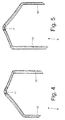
- the three-phase stator winding 8 comprises a series of "U"-shaped rigid bars 9, each comprising two legs 10 which are connected to one another by a cusp 11 (as shown more in detail in figures 3 , 4 and 5 ); the two legs 10 of the same bar 9 constitute two corresponding conductors of the stator winding 8.
- each "U"-shaped bar 9 has a "three-dimensional” fold, i.e. on two planes A and B that are perpendicular to one another.
- the cusp 11 of each "U"-shaped bar 9 has a fold that follows plane A, which is substantially parallel to the lying plane defined by the "U"-shaped bar 9 and is "S"-shaped; furthermore, the cusp 11 of each "U”-shaped bar 9 has a further fold that follows plane B, which is substantially perpendicular to the lying plane defined by the "U"-shaped bar 9 (i.e. it is substantially perpendicular to plane A) and is "U"-shaped.
- plane A laterally consists of two portions of cylindrical surface, which are centred on the central axis 3 of rotation of the electric machine 1 and have slightly different radii (since a leg 10 of the "U"-shaped bar 9 is inserted into a stator slot 7 placed in a more internal position, namely in correspondence to a smaller radius, while the other leg 10 of the "U"-shaped bar 9 is inserted into a stator slot 7 placed in a more external position, namely in correspondence to a bigger radius); furthermore, in plane A the two portions of cylindrical surface arranged on the sides are centrally joined to one another by an "S"-shaped central portion.
- plane B has a "U"-shape, which causes the corresponding bar 9 to take on a "U”-shape.
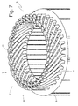
- the "S"-shaped fold along plane A causes the corresponding bar 9 to take on the shape needed both to allow the two legs 10 to be inserted into the corresponding stator slots 7 in different positions (a more internal and a more external position) and to allow the cusps 11 of all "U"-shaped bars 9 to be arranged one beside the other without any mechanical interference with one another (as shown in figure 7 ).
- the two legs 10 are inclined relative to one another (i.e. the two legs 10 form an acute angle between them) and each leg 10 is oriented so as to "face" the central axis 3 of rotation of the electric machine 1.
- the configuration of the "U"-shaped bars 9 described above it is possible to reduce the length (and therefore the total weight) of the cusps 11, in other words it is possible to reduce the quantity of copper to be found on the outside of the stator slots 7 (the copper to be found on the outside of the stator slots 7 is needed to enable electrical current to circulate in the stator winding 8, but it is completely useless for the purpose of delivering the mechanical torque to the shaft 2).
- the configuration of the "U"-shaped bars 9 described above allows the length (and therefore the total weight) of the cusps 11 to be optimized (minimized).
- the "U"-shaped bars 9 are inserted through the stator slots 7 defining an entry side 12, in which the cusps 11 of the "U"-shaped bars 9 are placed, and an exit side 13, in which the legs 10 of the "U"-shaped bars 9 are placed.
- each slot accommodates four legs 10 (namely four conductors of the stator winding 8) belonging to four corresponding "U"-shaped rigid bars 9 which are different from one another.
- the ends of the legs 10 of the "U"-shaped bars 9 are electrically connected to one another (welded) so as to form the electrical paths of the stator winding 8.
- the three-phase stator winding 8 comprises three power terminals 14 which constitute the electrical interface with the outside of the stator winding 8 and are electrically connected to an electronic power converter (not shown) which controls the synchronous electric machine 1.
- an insulating layer S with an annular shape and made of an electrically insulating material is interposed between the two internal circles and the two external circles of legs 10 coming out from the exit side 13 of the stator magnetic core 6.
- an electrically insulating material typically "Nomex®" insulating paper
- stator winding 8 With reference to figures 8-18 , below you can find a description of the way in which the stator winding 8 is built.
- the bars 9 are bent in the middle by 180° so as to become “U”-shaped and take on the shape shown in figures 3-6 .
- This bending operation is preferably carried out by means of an electronically controlled machine tool which gives each bar 9 its final shape in one single operation.
- the cusps 11 of the "U"-shaped bars 9 are configured in such a way that they are spaced apart by the same number of slots (that is six stator slots 7 in the embodiment shown in the accompanying drawings); in other words, between two legs 10 of the same "U"-shaped bar 9 there is always a skip of six stator slots 7.
- the legs 10 of the "U"-shaped bars 9 can all have the same length, or they can have different lengths (i.e.
- the legs 10 of some "U”-shaped bars 9 are slightly longer or shorter than the legs 10 of other "U”-shaped bars 9); the solution according to which the legs 10 of the "U”-shaped bars 9 all have the same length involves a higher consumption of copper, although it is easier to handle, and is therefore normally preferred in case of smaller production volumes.
- each "U”-shaped bar 9 is individually inserted (i.e. alone) into the corresponding two stator slots 7 (namely the two legs 10 of the "U"-shaped bar 9 are axially inserted into the corresponding two stator slots 7).
- only one "U"-shaped bar 9 at a time is inserted into two non-adjacent stator slots 7.
- each stator slot 7 is internally “coated” with an insulating layer (not shown) made of an electrically insulating material (typically "Nomex®” insulating paper).
- the legs 10 are not twisted all at once, they are twisted in groups; in other words, the legs 10 of the "U"-shaped bars 9 are divided into at least two groups which are twisted in two consecutive operations (i.e. not simultaneously). While a first group of legs 10 is being twisted, the legs 10 of the second group, which will be twisted at a later time, are temporarily axially moved along the stator slots 7, so as to reduce the length of the portion coming out from the stator slots 7 on the exit side 13 (typically until the length of portion of the legs 10 coming out from the stator slots 7 on the exit side 13 is zero or almost zero).
- the legs 10 belonging to the second group are not an obstacle to the legs 10 of the first group being twisted, and at the same time the legs 10 of the second group engage the stator slots 7 so as to help keep the legs 10 of the first group still during twisting.
- the legs 10 of the second group are axially moved in the opposite direction so as to go back to their original position and be twisted as well.
- the twisting of the legs 10 of the first group is made easier, because said twisting takes place without the obstacle posed by the legs 10 of the second group.
- the twisting of the legs 10 of the second group is easier anyway, since it takes place once the legs 10 of the first group have already been twisted and therefore take up much less axial space.
- each double fold of a leg 10 comprises an internal fold 15 (namely closer to the magnetic core 6 of the stator 5) in one direction and an external fold 16 (namely farther away from the magnetic core 6 of the stator 5) in the opposite direction.
- the internal fold 15 has a width of about 60° in a direction
- the external fold 15 has a width of about 60° in the opposite direction.
- Each stator slot 7 accommodates four corresponding legs 10 (belonging to four different corresponding "U"-shaped bars) which are twisted in alternately opposite directions through relative "Z"-shaped double folds. In other words, half of the legs 10 are twisted in a clockwise direction at a given angle, while the other half of the legs 10 are twisted in a counter-clockwise direction (that is in the opposite direction) at the same angle.
- each leg 10 has an initial segment 10a which is axially oriented (i.e. parallel to the central axis 3 of rotation of the electric machine 1, and therefore parallel to the stator slots 7), an inclined intermediate segment 10b and a final segment 10c which is axially oriented as well; the intermediate segment 10b joins the initial segment 10a and the final segment 10c, which are parallel to each other, together.
- the intermediate segment 10b is inclined by the same angle ⁇ (in the embodiment shown, about 60°) both relative to the initial segment 10a and relative to the final segment 10c; in other words, starting from the straight leg 10, the leg 10 is initially twisted at the bottom by an angle ⁇ so as to form the internal fold 15 (between the initial segment 10a and the intermediate segment 10b) and the leg 10 is then twisted at the top by the angle ⁇ so as to form the external fold 16 (between the intermediate segment 10b and the final segment 10c).
- ⁇ in the embodiment shown, about 60°
- each leg 10 due to the "Z"-shaped double fold, the initial segment 10a and the final segment 10c are parallel to one another (i.e. they are both axially oriented) and spaced apart from one another by a pitch that can take on a higher value P1 or a lower value P2 (in the embodiment shown in the accompanying drawings, pitch P1 corresponds to the distance existing between three stator slots 7, while pitch P2 corresponds to the distance existing between two and a half stator slots 7).
- pitch P1 In order to differentiate pitch P1 from pitch P2, it is not the twisting angle ⁇ that is varied (in fact, all legs 10 are always twisted by the same angle ⁇ in order to form the double folds), but rather the extension of the intermediate segment 10b (and, accordingly, the final segment 10c has a different length, too); in other words, in order to obtain the longer pitch P1, a longer intermediate segment 10b is used, while in order to obtain the shorter pitch P2, a shorter intermediate segment 10b is used, while always keeping the twisting angle ⁇ used to form the double folds unchanged.
- all "U"-shaped bars 9 are spaced apart by the same number of slots, i.e. between the two legs 10 of all “U”-shaped bars 9 there is a skip of six stator slots 7; as a consequence, in order to form the electrical paths of the stator winding 8, it is necessary that the legs 10 of the "U"-shaped bars 9 are differentiated in their "Z"-shaped double folds: as described above with reference to figure 11 , the majority of the legs 10 of the "U"-shaped bars 9 have a standard "Z"-shaped double fold with pitch P1 (corresponding to the distance existing between three stator slots 7), while a small part of the legs 10 of the "U”-shaped bars 9 have a shortened “Z"-shaped double fold with pitch P2 (corresponding to the distance existing between two and a half stator slots 7).
- the legs 10 of the "U"-shaped bars 9 having the shortened “Z"-shaped double fold (pitch P2) are concentrated in an interconnection area 17 of the stator winding 8, which has an extension of about one fourth of the whole stator winding 8 and which also accommodates the power terminals 14.
- the upper ends of the legs 10 of the "U"-shaped bars 9 are electrically connected to one another (by means of laser welding, as described more in detail below) so as to form the electrical paths of the stator winding 8.
- some legs 10 In correspondence to the interconnection area 17 of the stator winding 8, some legs 10 have longer (more extended) terminal ends 10c, so as to form some of the electrical connections of the stator winding 8 as described below.
- each phase comprises two corresponding connection bridges 18, therefore the whole stator winding 8 has a total of six connection bridges 18.
- each connection bridge 18 is made of a flat plate arranged perpendicular to the central axis 3 of rotation of the electric machine 1 and has two opposite seats 19 that engage the ends of the respective legs 10.
- each connection bridge 18 comprises seats 19, each of which is "U"-shaped and suited to receive and accommodate the end of a corresponding leg 10.
- Each seat 19 initially has a larger cross section than the cross section of the corresponding leg 10, so that the leg 10 itself can be inserted into the seat 19 with a certain clearance; in other words, each seat 19 is initially larger than the corresponding leg 10 in order to accommodate the leg 10 with a certain clearance and therefore allow the end of the leg 10 to be easily inserted.
- the seat 19 is caused to shrink by means of plastic deformation, so as for it to be tight around the leg 10 (i.e. to firmly adhere to the leg 10); in particular, the seat 19 is deformed towards the leg 10 by means of a suitable gripper, so as to be in close contact with (also exerting a certain pressure on) the leg 10 itself.
- connection bridge 18 are initially larger than the corresponding legs 10
- coupling the connection bridge 18 to the stator winding 8 proves to be simple and quick (it can therefore be easily automated); furthermore, thanks to the fact that the seats 19 of each connection bridge 18 are plastically deformed so as for them to be tight around the corresponding legs 10, it is possible to obtain an optimal (mechanical and therefore electric) contact between the connection bridge 18 and the corresponding legs 10.
- connection bridge 18 is made up of a central body with a substantially constant cross-section and of a series of appendages, which project from the central body and are perpendicular to the central body itself; each seat 19 is delimited, on the rear side, by the central body and is laterally delimited by a pair of appendages that are arranged one in front of the other.
- one appendage is linear (i.e. it has a linear shape in its plan view) and the other appendage is "L"-shaped (i.e.
- an appendage in the embodiments shown in the accompanying drawings, the linear appendage
- the other appendage in the embodiments shown in the accompanying drawings, the "L"-shaped appendage
- the deformation of each seat 19 essentially (but not exclusively) involves the appendage that initially forms an obtuse angle with the central body.
- the appendage initially forming an obtuse angle with the central body has wider deformation margins, because, before the deformation takes place, it is slightly farther away from the end of the corresponding leg 10 than the other appendage initially forming a right angle with the central body.
- stator slots 7 i.e. with a skip of six stator slots 7 obtained by means of the standard "Z"-shaped double fold with pitch P1, which is equal to three slots; furthermore, every time the magnetic core 6 of the stator makes a complete revolution, there must be a skip of five stator slots 7 (obtained by means of the shortened "Z"-shaped double fold with pitch P2, which is equal to two and a half slots) or a skip of 7 stator slots 7 (obtained by means of the connection bridges 18), so as to follow the electrical paths of the stator winding 8.
- an insulating support 20 which houses the connection bridges 18 and is arranged under the connection bridges 18.
- the insulating support 20 is made of an electrically insulating plastic material.
- the insulating support 20 comprises a base 21, which is shaped as a circular arc and has a lower surface, which rests against the ends of the legs 10 arranged under it, and an upper surface, on which the connection bridges 18 rest.
- the base 21 of the insulating support 20 has a plurality of through holes 22, into which some legs are inserted 10, which have to pass through the insulating support 20 in order to be connected to the connection bridges 18 or to be connected to further elements (described below) arranged above the connection bridges 18.
- the insulating support 20 comprises a plurality of positioning elements 23, which project downwards from the lower surface of the base 21 and are interlocked in gaps available between the ends of the legs 10 arranged under them (as shown in figure 12 ), so as to both ensure a correct positioning of the insulating support 20, and mechanically constrain the insulating support 20 to the underlying part of the stator winding 8.
- the positioning elements 23 are arranged perpendicular to the base 21.
- the insulating support 20 comprises a plurality of columns 24, which project upwards from the upper surface of the base 21 (i.e. from the opposite side and in the opposite direction with respect to the positioning elements 23) and provide a mechanical support for further elements (described below) arranged above the insulating support 20.
- the columns 24 are arranged circumferentially both on the internal edge and on the external edge of the insulating support 20.
- each seat 25 is made up of restraining elements 26, which project upwards from the upper surface of the base 21 and are arranged in correspondence to the edge of the corresponding connection bridge 18; at least part of the restraining elements 26 have a tooth 27, which rests on an upper surface of the corresponding connection bridge 18 following an elastic deformation of the restraining element 26 itself.
- each connection bridge 18 is forcedly inserted into the corresponding seat 25, so as to determine an elastic deformation of at least part of the restraining elements 26; accordingly, in order to extract a connection bridge 18 from the corresponding seat 25, it is necessary to elastically deform at least part of the restraining elements 26.
- connection bridges 18 make the coupling of the connection bridges 18 to the stator winding 8 considerably easier; in particular, it is possible to pre-assemble (and lock in an interlocking manner) the connection bridges 18 into the corresponding seats 25 of the insulating support 20 far from the stator winding 8 and therefore couple, with a single operation, the insulating support 20, together with all the connection bridges 18, to the stator winding 8. Furthermore, the insulating support 20 allows the connection bridges 18 to be firmly kept in the desired position during the construction of the stator winding 8 (i.e. before the seats 19 of the connection bridges 18 are tightened around the ends of the corresponding legs 10 and before the connection bridges 18 are welded to the ends of the corresponding legs 10).
- connection bridge 28 which is made of a flat plate arranged perpendicular to the central axis 3 of rotation of the electric machine 1 and has three seats, which engage the ends of the respective legs 10.
- the connection bridges 28 are similar to the connection bridges 20 described above and therefore comprise respective seats, which are plastically deformed once the ends of the corresponding legs 10 have been inserted into them.
- the stator winding 8 shown in the accompanying drawings comprises two star-connections which, in turn, are connected in parallel to one another (as described more in detail below).
- the two connection bridges 28 are arranged above the six connection bridges 18.
- an insulating support 29 is provided, which houses the connection bridges 28, is arranged under the connection bridges 28, and is similar to the insulating support 20.
- the insulating support 29 rests, on the lower side, on the top of the columns 24 of the insulating support 20.
- the only substantial difference (obviously apart from the shape and the arrangement of the seats 25) between the insulating support 29 and the insulating support 20 is the fact that the insulating support 29 does not have the positioning elements 23, since it rests on the columns 24 of the underlying insulating support 20.
- the insulating support 29 comprises a base which is crossed by through holes like the insulating support 20, it comprises columns like the insulating support 20, and it has seats provided with restraining elements, which, in case, may have teeth, like the insulating support 20.
- a connection bridge 30 which has a power terminal 14, is arranged above the connection bridges 28, and is made of a flat plate arranged perpendicular to the central axis 3 of rotation of the electric machine 1 and has two seats, which engage the ends of the respective legs 10.
- the connection bridge 30 is similar to the connection bridges 20 described above and therefore comprises respective seats, which are plastically deformed once the ends of the corresponding legs 10 have been inserted into them.
- an insulating support 31 is provided, which houses the connection bridge 30, is arranged under the connection bridge 30, and is similar to the insulating supports 20 and 29.
- the insulating support 31 rests, on the lower side, on the top of the columns of the insulating support 29.
- the only substantial difference (obviously apart from the shape and the arrangement of the seats 25) between the insulating support 31 and the insulating support 20 is the fact that the insulating support 31 does not have the positioning elements 23, since it rests on the columns of the underlying insulating support 29.
- the insulating support 31 comprises a base which is crossed by through holes like the insulating support 20, it comprises columns like the insulating support 20, and it has seats provided with restraining elements, which, in case, may have teeth, like the insulating support 20.
- a connection bridge 32 which has a power terminal 14, is arranged above the connection bridge 30, and is made of a flat plate arranged perpendicular to the central axis 3 of rotation of the electric machine 1 and has two seats, which engage the ends of the respective legs 10.
- the connection bridge 32 is similar to the connection bridges 20 described above and therefore comprises respective seats, which are plastically deformed once the ends of the corresponding legs 10 have been inserted into them.
- an insulating support 33 is provided, which houses the connection bridge 32, is arranged under the connection bridge 32, and is similar to the insulating supports 20, 29 and 31.
- the insulating support 33 rests, on the lower side, on the top of the columns of the insulating support 31.
- the only substantial difference (obviously apart from the shape and the arrangement of the seats 25) between the insulating support 33 and the insulating support 20 is the fact that the insulating support 33 does not have the positioning elements 23, since it rests on the columns of the underlying insulating support 31.
- the insulating support 33 comprises a base which is crossed by through holes like the insulating support 20, it comprises columns like the insulating support 20, and it has seats provided with restraining elements, which, in case, have teeth, like the insulating support 20.
- a connection bridge 34 which has a power terminal 14, is arranged above the connection bridge 32, and is made of a flat plate arranged perpendicular to the central axis 3 of rotation of the electric machine 1 and has two seats, which engage the ends of the respective legs 10.
- the connection bridge 34 is similar to the connection bridges 20 described above and therefore comprises respective seats, which are plastically deformed once the ends of the corresponding legs 10 have been inserted into them.
- an insulating support 35 is provided, which houses the connection bridge 34, is arranged under the connection bridge 34, and is similar to the insulating supports 20, 29, 31 and 33.
- the insulating support 35 rests, on the lower side, on the top of the columns of the insulating support 33.
- the only substantial difference (obviously apart from the shape and the arrangement of the seats 25) between the insulating support 35 and the insulating support 20 is the fact that the insulating support 35 does not have the positioning elements 23, since it rests on the columns of the underlying insulating support 33.
- the insulating support 35 comprises a base which is crossed by through holes like the insulating support 20, it comprises columns like the insulating support 20, and it has seats provided with restraining elements, which, in case, may have teeth, like the insulating support 20.
- connection bridges 30, 32 and 34 each power terminal 14 is electrically connected to the ends of two legs 10 which constitute respective terminals of a star connection of the stator winding 8 and which project beyond the corresponding support elements 31, 33 and 35; in this way, the connection bridges 30, 32 and 34 establish the connection in parallel between the two star-connections of the stator winding 8.
- connection bridges 18, 28, 30, 32 and 34 are used, which are arranged one on top of the other (i.e. piled on top of one another); according to other perfectly equivalent embodiments, it is possible to use a different number (for example, four or six) of connection bridges.
- the welding operation is performed in a welding station 36 comprising an emitting device 37 which is designed to produce and emit a laser beam 38, which is suited to melt copper, i.e. the metal making up the stator winding 8.
- the welding station 36 also comprises a video camera 39, which is designed to capture digital images of the elements that have to be welded together (the legs 10 of the "U"-shaped bars 9 in the embodiment shown in figure 19 ).
- the welding station 36 comprises an illuminating device 40, which is suited to illuminate the elements that have to be welded together (the legs 10 of the "U"-shaped bars 9 in the embodiment shown in figure 19 ); preferably, the illuminating device 40 has an annular shape, is arranged around the lens of the video camera 39, and is suited to emit a red light (which enables an optimization of the vision of the elements to be welded during the welding operations) by means of a LED matrix.
- a compression device 41 is provided, which is mechanically coupled to the legs 10 that have to be welded to one another, so as to push the legs 10 one towards the other and therefore arrange the legs 10 themselves in close contact with one another in order to help establish an optimal electrical connection.
- the compression device 41 comprises two jaws 42 which are arranged on opposite sides of the group of legs 10 and are mechanically connected to one another so as to tighten the legs 10 between them.
- Figures 20-25 show how the ends of two adjacent legs 10 are welded in the welding station 36; the two metal elements that have to be welded to one another, i.e. the two legs 10, are arranged one beside the other and have respective upper surfaces 43, which are arranged coplanar to one another and have at least one common edge 44.
- FIG. 20 schematically shows only the two legs 10 that have to be welded to one another and the jaws 42 are directly pressed against both legs 10, while the jaws 42 normally compress a group of four legs 10, as shown in figure 19 .
- the two legs 10 come into close contact, thus eliminating undesired gaps, if there are any between the two legs 10 in correspondence to the common edge 44.
- the video camera 39 captures a digital image of the two upper surfaces 43 of both legs 10.
- a control unit analyzes the digital image, in order to both determine the position of the external edges of the two upper surfaces 43 (highlighted with a dotted line in figure 22 ), and determine the position of the corners of the external edges of the two upper surfaces 43.
- the control unit determines the position of the center (namely of the barycenter) of the two upper surfaces 43 (indicated by a dotted line cross in figure 22 ).
- the external edges of the upper surfaces 43 and the center of the two upper surfaces 43 constitute geometric references that the control unit uses to control the position of the laser beam 38 (that is to control where the laser beam 38 hits the upper surfaces 43).
- the control unit controls the emitting device 37 in order to aim, at the upper surfaces 43 of the two legs 10, a laser beam 38, which is suited to melt copper (i.e. the metal making up the legs 10) and is fed along a welding line 45 which is perpendicular to the common edge 44 and extends through the common edge 44 itself.
- the position of the welding line 45 is determined based on the position of the center of the two upper surfaces 43, while the orientation of the welding line 45 is determined based on the external edges of the two upper surfaces 43 (in particular, laser beam 38 production is controlled in such a way that the laser beams 38 are parallel to the external edges of the two upper surfaces 43 which are perpendicular to the common edge 44).
- the laser beam 38 drawing the welding line 45 on the upper surfaces 43 of the two legs 10 causes part of the metal making up the legs 10 to melt, thus determining the formation of a molten metal bath 46 which places itself on both sides of the welding line 45.
- the control unit controls the emitting device 37 in order to aim, at the upper surfaces 43 of the two legs 10, a laser beam 38, which is suited to melt copper (i.e. the metal making up the legs 10) and is fed along a welding line 47 which is perpendicular to the common edge 44, extends through the common edge 44, is parallel to and spaced apart from the line 45 and has a length that is smaller than the one of the line 45.
- a laser beam 38 which is suited to melt copper (i.e. the metal making up the legs 10) and is fed along a welding line 47 which is perpendicular to the common edge 44, extends through the common edge 44, is parallel to and spaced apart from the line 45 and has a length that is smaller than the one of the line 45.
- the position of the welding line 47 is determined based on the position of the center of the two upper surfaces 43, while the orientation of the welding line 47 is determined based on the external edges of the two upper surfaces 43 (in particular, laser beam 38 production is controlled in such a way that the laser beams 38 are parallel to the external edges of the two upper surfaces 43 which are perpendicular to the common edge 44).
- the laser beam 38 drawing the welding line 47 on the upper surfaces 43 of the two legs 10 causes part of the metal making up the legs 10 to melt, thus determining the formation of a molten metal bath 48 which places itself on both sides of the welding line 47 and merges with the previously generated molten metal bath 46 (thus forming a single molten metal bath).
- the welding line 47 is shorter than the welding line 45 allows the weld to be well balanced, because, even if there is a shorter welding line 47, the molten metal bath 48 has substantially the same volume as the molten metal bath 46; as a matter of fact, the welding line 47 is performed when the upper surfaces 43 of the two legs 10 have already been heated by the previous welding line 45, and therefore, even though it delivers an overall smaller quantity of heat, it causes a substantially equal quantity of metal to melt.
- a further (third) welding line which is perpendicular to the common edge 44, extends through the common edge 44 itself, is parallel to and spaced apart from the welding line 47 and has a length that is smaller than the one of the welding line 47.
- the welding lines 45 and 47 are not centred relative to one another.
- the welding line 45 is symmetrically divided by the common edge 44, while the welding line 47 is asymmetrically divided by the common edge 44; in this way the risk of molten metal burrs forming outside the upper surfaces 43 of the two legs 10 can be further reduced.
- each welding line 45 and 47 extends from a starting point arranged on a leg 10 to an arrival point arranged on the other leg 10, the starting points of the two welding lines 45 and 47 are arranged at the same distance from the common edge 44, and the arrival points of the two welding lines 45 and 47 are arranged at different distances from the common edge 44.
- the jaws 42 of the compression device 41 are uncoupled from the legs 10, thus putting an end to the welding operations. While the welding is being performed, the jaws 42 of the compression device 41 push the two legs 10 - and keep them pushed - towards one another along a pushing direction that is perpendicular to the common edge 44. Said push is generated before starting to emit the laser beams 38 and is normally kept up until the molten metal baths 46 and 48 have at least partially cooled down.
- the two jaws 42 of the compression device 41 have an annular shape, are mounted on the stator winding 8 before beginning to weld and are removed from the stator winding 8 at the end of the welding process.
- An internal jaw 42 is arranged on the inside of the stator winding 8 in direct contact with the most internal legs 10
- an external jaw 42 is arranged on the outside of the stator winding 8 in direct contact with the most external legs 10, so as to push the most external legs 10 towards the most internal legs 10 and vice versa.
- the above-described ways in which laser welding is performed have numerous advantages, since they allow the welding process to be effective (i.e. a process resulting in a mechanically robust, electrically low resistance and long lasting weld), efficient (i.e. with very limited processing times) and simple (i.e. which can easily be automated and performed with precision without adopting any special measures).
- the above-described ways in which laser welding is performed do not require a prior peeling (i.e. removing of the external insulating layer) of the final ends of the legs 10 in correspondence to the upper surfaces 43; in other words, in order to perform laser welding as described above, it is not necessary to peel (i.e. remove the external insulating layer of) the final ends of the legs 10 in correspondence to the upper surfaces 43.
- the electric machine 1 shown in the accompanying drawings is a synchronous electric machine with permanent magnet rotor, but, obviously, the electric machine 1 may be of any other type (for example asynchronous and therefore without permanent magnets in the rotor).
Landscapes
- Engineering & Computer Science (AREA)
- Physics & Mathematics (AREA)
- Optics & Photonics (AREA)
- Power Engineering (AREA)
- Plasma & Fusion (AREA)
- Mechanical Engineering (AREA)
- Manufacturing & Machinery (AREA)
- Manufacture Of Motors, Generators (AREA)
- Laser Beam Processing (AREA)
Abstract
Description
- The present invention relates to a laser welding method to weld two adjacent metal elements of a stator winding with rigid bars for an electric machine.
- Patent application
EP2437378A1 describes an electric machine having a stator winding with rigid bars. In a stator winding made of rigid bars, a series of rigid bars are used, which are initially shaped into a "U" and are then axially inserted into the stator slots, thus defining an entry side, in which the cusps of the "U"-shaped bars are placed, and an exit side, in which the legs (i.e. the straight portions) of the "U"-shaped bars are placed. Once the bars have been inserted into the stator slots, the legs on the exit side are bent and then the free ends of the legs are connected to one another by means of welding so as to form the electrical paths of the stator winding. - A welding technique that can be used to weld the ends of two legs, which are arranged one beside the other, together is laser welding, according to which a laser beam is aimed at the upper surfaces of the two legs, said laser beam being suited to melt the metal making up the legs and being fed along a welding line which extends through a common edge between the two upper surfaces.
- Patent application
US2003159269A1 describes a laser welding method to weld twoadjacent metal elements figures 1 and3 ) with rigid bars (shown infigure 4 ) for an electric machine. The twometal elements metal elements metal elements 22 and 24). - The object of the present invention is to provide a laser welding method to weld two adjacent metal elements of a stator winding with rigid bars for an electric machine, said welding method being easy and cheap to be implemented and, at the same time, effective, efficient and quick.
- According to the present invention, a laser welding method is provided to weld two adjacent metal elements of a stator winding with rigid bars for an electric machine according to the appended claims.
- The present invention will now be described with reference to the accompanying drawings, which show a nonlimiting embodiment thereof, wherein:
-
figure 1 is a schematic, cross-sectional view, with parts removed for greater clarity, of an electric machine according to the present invention; -
figure 2 is a schematic, perspective view, with parts removed for greater clarity, of a stator of the electric machine offigure 1 ; -
figure 3 is a schematic, perspective view of a "U"-shaped rigid bar that is part of a stator winding of the stator offigure 2 ; -
figures 4 and 5 are two different perspective views on a larger scale of a cusp of the rigid bar offigure 3 ; -
figure 6 is a perspective view highlighting the planes of curvature of a cusp of the rigid bar offigure 3 ; -
figure 7 is a perspective view of an entry side of the stator offigure 2 ; -
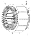
figure 8 is a perspective view of the stator offigure 2 during the construction of the stator winding; -
figures 9 and10 are two views on a larger scale of respective details offigure 8 ; -
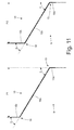
figure 11 is a schematic view showing how corresponding legs of two different "U"-shaped bars of the stator winding are twisted into a "Z"-shape; -
figure 12 is a further perspective view of part of the stator offigure 2 during the construction of the stator winding; -
figure 13 is a perspective view of a support element which is coupled to connection bridges of the stator winding; -
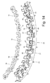
figure 14 is an exploded perspective view of the support element offigure 13 ; -
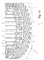
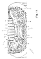
figures 15-18 are further perspective views of part of the stator offigure 2 during the construction of the stator winding; -
figure 19 is a schematic view of a welding station which is used during the construction of the stator winding; -
figures 20-25 are six schematic views showing the steps involved in the welding of two adjacent legs of the stator winding. - In
figure 1 , number 1 indicates, as a whole, a synchronous electric machine for the automotive industry of the reversible type (i.e. which can act both as an electric motor, by absorbing electrical energy and generating a mechanical driving torque, and as an electric generator, by absorbing mechanical energy and generating electrical energy). The electric machine 1 comprises ashaft 2, which is mounted in a rotatory manner so as to rotate around acentral axis 3 of rotation, apermanent magnet rotor 4 splined to theshaft 2 so as to rotate together with theshaft 2 itself, and a cylindricaltubular stator 5 arranged around therotor 4 so as to surround therotor 4 itself. - The
stator 5 comprises amagnetic core 6, which consists of a series of laminations bound into packs and has a tubular shape with a central hole; themagnetic core 6 is longitudinally crossed by thirty-six stator slots 7 which are uniformly distributed along the internal side of themagnetic core 6 and house a three-phase stator winding 8 (shown infigure 2 ); obviously, the number of slots 7 may be different (for example, forty-eight or seventy-two stator slots 7). In the embodiment shown in the accompanying drawings, the three-phase stator winding 8 is distributed in thirty-six stator slots 7 and thepermanent magnet rotor 4 comprises six poles; as a consequence, the synchronous electric machine 1 has two slots for each pole and for each phase. - According to
figure 2 , the three-phase stator winding 8 comprises a series of "U"-shapedrigid bars 9, each comprising twolegs 10 which are connected to one another by a cusp 11 (as shown more in detail infigures 3 ,4 and 5 ); the twolegs 10 of thesame bar 9 constitute two corresponding conductors of the stator winding 8. - As shown more in detail in
figure 6 , thecusp 11 of each "U"-shaped bar 9 has a "three-dimensional" fold, i.e. on two planes A and B that are perpendicular to one another. In particular, thecusp 11 of each "U"-shaped bar 9 has a fold that follows plane A, which is substantially parallel to the lying plane defined by the "U"-shaped bar 9 and is "S"-shaped; furthermore, thecusp 11 of each "U"-shaped bar 9 has a further fold that follows plane B, which is substantially perpendicular to the lying plane defined by the "U"-shaped bar 9 (i.e. it is substantially perpendicular to plane A) and is "U"-shaped. - As clearly shown in
figure 6 , plane A laterally consists of two portions of cylindrical surface, which are centred on thecentral axis 3 of rotation of the electric machine 1 and have slightly different radii (since aleg 10 of the "U"-shaped bar 9 is inserted into a stator slot 7 placed in a more internal position, namely in correspondence to a smaller radius, while theother leg 10 of the "U"-shaped bar 9 is inserted into a stator slot 7 placed in a more external position, namely in correspondence to a bigger radius); furthermore, in plane A the two portions of cylindrical surface arranged on the sides are centrally joined to one another by an "S"-shaped central portion. As clearly shown infigure 6 , plane B has a "U"-shape, which causes thecorresponding bar 9 to take on a "U"-shape. The "S"-shaped fold along plane A causes thecorresponding bar 9 to take on the shape needed both to allow the twolegs 10 to be inserted into the corresponding stator slots 7 in different positions (a more internal and a more external position) and to allow thecusps 11 of all "U"-shaped bars 9 to be arranged one beside the other without any mechanical interference with one another (as shown infigure 7 ). It should be pointed out that, in each "U"-shaped bar 9, the twolegs 10 are inclined relative to one another (i.e. the twolegs 10 form an acute angle between them) and eachleg 10 is oriented so as to "face" thecentral axis 3 of rotation of the electric machine 1. - Thanks to the configuration of the "U"-
shaped bars 9 described above, it is possible to build the whole stator winding 8 by bending thebars 9 in correspondence to thecusps 11 in a single bending step before inserting thebars 9 into the corresponding stator slots 7; in other words, once the "U"-shaped bars 9 have been inserted into the corresponding stator slots 7, thecusps 11 are not subject to any further bending. Furthermore, thanks to the configuration of the "U"-shaped bars 9 described above, it is possible to insert the "U"-shaped bars 9 into the corresponding stator slots 7 extremely easily (i.e. with little effort), since the configuration prevents all mechanical interferences between the "U"-shaped bars 9, which would require the insertion of the bars to be forced (namely the bars would have to be pushed with force) in order to slightly deform the "U"-shaped bars 9 themselves; in this way, the construction of the stator winding 8 is quick and easy and, above all, there is no risk of damage to the external insulation of the "U"-shaped bars 9. - Furthermore, thanks to the configuration of the "U"-
shaped bars 9 described above, it is possible to reduce the length (and therefore the total weight) of thecusps 11, in other words it is possible to reduce the quantity of copper to be found on the outside of the stator slots 7 (the copper to be found on the outside of the stator slots 7 is needed to enable electrical current to circulate in the stator winding 8, but it is completely useless for the purpose of delivering the mechanical torque to the shaft 2). In other words, the configuration of the "U"-shaped bars 9 described above allows the length (and therefore the total weight) of thecusps 11 to be optimized (minimized). - According to
figure 2 , the "U"-shaped bars 9 are inserted through the stator slots 7 defining anentry side 12, in which thecusps 11 of the "U"-shaped bars 9 are placed, and anexit side 13, in which thelegs 10 of the "U"-shaped bars 9 are placed. In particular, each slot accommodates four legs 10 (namely four conductors of the stator winding 8) belonging to four corresponding "U"-shapedrigid bars 9 which are different from one another. The ends of thelegs 10 of the "U"-shaped bars 9 are electrically connected to one another (welded) so as to form the electrical paths of the stator winding 8. - According to
figure 2 , the three-phase stator winding 8 comprises threepower terminals 14 which constitute the electrical interface with the outside of the stator winding 8 and are electrically connected to an electronic power converter (not shown) which controls the synchronous electric machine 1. - According to a preferred (though not limiting) embodiment shown in
figure 2 , an insulating layer S with an annular shape and made of an electrically insulating material (typically "Nomex®" insulating paper) is interposed between the two internal circles and the two external circles oflegs 10 coming out from theexit side 13 of the statormagnetic core 6. Alternatively, it is possible to interpose three insulating layers S with an annular shape and made of an electrically insulating material between the four circles oflegs 10, or the insulating layers S with an annular shape and made of an electrically insulating material may not be present at all. - With reference to
figures 8-18 , below you can find a description of the way in which the stator winding 8 is built. - At first (and as described above) the
bars 9 are bent in the middle by 180° so as to become "U"-shaped and take on the shape shown infigures 3-6 . This bending operation is preferably carried out by means of an electronically controlled machine tool which gives eachbar 9 its final shape in one single operation. Thecusps 11 of the "U"-shaped bars 9 are configured in such a way that they are spaced apart by the same number of slots (that is six stator slots 7 in the embodiment shown in the accompanying drawings); in other words, between twolegs 10 of the same "U"-shaped bar 9 there is always a skip of six stator slots 7. Furthermore, thelegs 10 of the "U"-shaped bars 9 can all have the same length, or they can have different lengths (i.e. thelegs 10 of some "U"-shaped bars 9 are slightly longer or shorter than thelegs 10 of other "U"-shaped bars 9); the solution according to which thelegs 10 of the "U"-shaped bars 9 all have the same length involves a higher consumption of copper, although it is easier to handle, and is therefore normally preferred in case of smaller production volumes. - Once the "U"-
shaped bars 9 are ready (in particular, in the stator winding 8 shown in the accompanying figures there are seventy-two "U"-shaped bars 9), each "U"-shaped bar 9 is individually inserted (i.e. alone) into the corresponding two stator slots 7 (namely the twolegs 10 of the "U"-shaped bar 9 are axially inserted into the corresponding two stator slots 7). In other words, only one "U"-shaped bar 9 at a time is inserted into two non-adjacent stator slots 7. Preferably, before inserting the "U"-shaped bars 9 into the stator slots 7, each stator slot 7 is internally "coated" with an insulating layer (not shown) made of an electrically insulating material (typically "Nomex®" insulating paper). - Once all the seventy-two "U"-
shaped bars 9 have been inserted into the stator slots 7, thecorresponding legs 10 coming out from theexit side 13 of themagnetic core 6 are twisted through relative double folds so as to take on a "Z"-shape as shown infigure 8 . Alternatively, at first only a part (normally half) of the "U"-shaped bars 9 is inserted and, once this first part of the "U"-shaped bars 9 has been inserted, thecorresponding legs 10 coming out from theexit side 13 of themagnetic core 6 are twisted through relative double folds so as to take on a "Z"-shape; subsequently, the remaining part (normally the remaining half) of the "U"-shaped bars 9 is also inserted and, once the remaining part of the "U"-shaped bars 9 has been inserted, thecorresponding legs 10 coming out from theexit side 13 of themagnetic core 6 are twisted through relative double folds so as to take on a "Z"-shape. - According to a preferred embodiment, during the twisting of the
legs 10 of the "U"-shaped bars 9, thelegs 10 are not twisted all at once, they are twisted in groups; in other words, thelegs 10 of the "U"-shaped bars 9 are divided into at least two groups which are twisted in two consecutive operations (i.e. not simultaneously). While a first group oflegs 10 is being twisted, thelegs 10 of the second group, which will be twisted at a later time, are temporarily axially moved along the stator slots 7, so as to reduce the length of the portion coming out from the stator slots 7 on the exit side 13 (typically until the length of portion of thelegs 10 coming out from the stator slots 7 on theexit side 13 is zero or almost zero). In this way thelegs 10 belonging to the second group are not an obstacle to thelegs 10 of the first group being twisted, and at the same time thelegs 10 of the second group engage the stator slots 7 so as to help keep thelegs 10 of the first group still during twisting. Once the first group oflegs 10 have been twisted, thelegs 10 of the second group are axially moved in the opposite direction so as to go back to their original position and be twisted as well. In this way, the twisting of thelegs 10 of the first group is made easier, because said twisting takes place without the obstacle posed by thelegs 10 of the second group. The twisting of thelegs 10 of the second group is easier anyway, since it takes place once thelegs 10 of the first group have already been twisted and therefore take up much less axial space. - Once the twisting of the
legs 10 coming out from theexit side 13 of themagnetic core 6 has been completed, and only if necessary, somelegs 10 are cut (i.e. trimmed) so as to give them the desired length. - As shown more in detail in the enlargements of
figures 9 and10 , each double fold of aleg 10 comprises an internal fold 15 (namely closer to themagnetic core 6 of the stator 5) in one direction and an external fold 16 (namely farther away from themagnetic core 6 of the stator 5) in the opposite direction. By way of example, for eachleg 10, theinternal fold 15 has a width of about 60° in a direction and theexternal fold 15 has a width of about 60° in the opposite direction. Each stator slot 7 accommodates four corresponding legs 10 (belonging to four different corresponding "U"-shaped bars) which are twisted in alternately opposite directions through relative "Z"-shaped double folds. In other words, half of thelegs 10 are twisted in a clockwise direction at a given angle, while the other half of thelegs 10 are twisted in a counter-clockwise direction (that is in the opposite direction) at the same angle. - According to
figure 11 , once the "Z"-shaped double twisting has been performed, eachleg 10 has aninitial segment 10a which is axially oriented (i.e. parallel to thecentral axis 3 of rotation of the electric machine 1, and therefore parallel to the stator slots 7), an inclinedintermediate segment 10b and afinal segment 10c which is axially oriented as well; theintermediate segment 10b joins theinitial segment 10a and thefinal segment 10c, which are parallel to each other, together. In eachleg 10, theintermediate segment 10b is inclined by the same angle α (in the embodiment shown, about 60°) both relative to theinitial segment 10a and relative to thefinal segment 10c; in other words, starting from thestraight leg 10, theleg 10 is initially twisted at the bottom by an angle α so as to form the internal fold 15 (between theinitial segment 10a and theintermediate segment 10b) and theleg 10 is then twisted at the top by the angle α so as to form the external fold 16 (between theintermediate segment 10b and thefinal segment 10c). - In each
leg 10, due to the "Z"-shaped double fold, theinitial segment 10a and thefinal segment 10c are parallel to one another (i.e. they are both axially oriented) and spaced apart from one another by a pitch that can take on a higher value P1 or a lower value P2 (in the embodiment shown in the accompanying drawings, pitch P1 corresponds to the distance existing between three stator slots 7, while pitch P2 corresponds to the distance existing between two and a half stator slots 7). In order to differentiate pitch P1 from pitch P2, it is not the twisting angle α that is varied (in fact, alllegs 10 are always twisted by the same angle α in order to form the double folds), but rather the extension of theintermediate segment 10b (and, accordingly, thefinal segment 10c has a different length, too); in other words, in order to obtain the longer pitch P1, a longerintermediate segment 10b is used, while in order to obtain the shorter pitch P2, a shorterintermediate segment 10b is used, while always keeping the twisting angle α used to form the double folds unchanged. - As already mentioned above, all "U"-shaped
bars 9 are spaced apart by the same number of slots, i.e. between the twolegs 10 of all "U"-shapedbars 9 there is a skip of six stator slots 7; as a consequence, in order to form the electrical paths of the stator winding 8, it is necessary that thelegs 10 of the "U"-shapedbars 9 are differentiated in their "Z"-shaped double folds: as described above with reference tofigure 11 , the majority of thelegs 10 of the "U"-shapedbars 9 have a standard "Z"-shaped double fold with pitch P1 (corresponding to the distance existing between three stator slots 7), while a small part of thelegs 10 of the "U"-shapedbars 9 have a shortened "Z"-shaped double fold with pitch P2 (corresponding to the distance existing between two and a half stator slots 7). As an alternative to the shortened "Z"-shaped double fold with pitch P2 (corresponding to the distance existing between two and a half stator slots 7), it may be possible to use an extended version of the "Z"-shaped double fold with a pitch P1 (corresponding to the distance existing between three stator slots 7). - As shown in
figure 8 , thelegs 10 of the "U"-shapedbars 9 having the shortened "Z"-shaped double fold (pitch P2) are concentrated in aninterconnection area 17 of the stator winding 8, which has an extension of about one fourth of the whole stator winding 8 and which also accommodates thepower terminals 14. - Once the
legs 10 of the "U"-shapedbars 9 have been twisted, the upper ends of thelegs 10 of the "U"-shapedbars 9 are electrically connected to one another (by means of laser welding, as described more in detail below) so as to form the electrical paths of the stator winding 8. - In correspondence to the
interconnection area 17 of the stator winding 8, somelegs 10 have longer (more extended) terminal ends 10c, so as to form some of the electrical connections of the stator winding 8 as described below. - As shown in
figure 12 , in order to allow the electrical paths of the stator winding 8 to be formed in the part of the stator winding 8 corresponding to each phase, the ends of at least one pair of non-adjacent legs 10 (which therefore can not be directly welded to one another) are electrically connected to one another by means of aconnection bridge 18. As shown infigure 12 , in the stator winding 8 pictured in the accompanying drawings each phase comprises two corresponding connection bridges 18, therefore the whole stator winding 8 has a total of six connection bridges 18. According to a preferred embodiment, eachconnection bridge 18 is made of a flat plate arranged perpendicular to thecentral axis 3 of rotation of the electric machine 1 and has twoopposite seats 19 that engage the ends of therespective legs 10. Once the ends of thelegs 10 have been coupled to the corresponding connection bridges 18, the end of eachleg 10 is welded to thecorresponding connection bridge 18 by means of the laser technique (as described more in detail below). - According to a preferred embodiment shown in
figures 12 ,13 and14 , eachconnection bridge 18 comprisesseats 19, each of which is "U"-shaped and suited to receive and accommodate the end of acorresponding leg 10. Eachseat 19 initially has a larger cross section than the cross section of thecorresponding leg 10, so that theleg 10 itself can be inserted into theseat 19 with a certain clearance; in other words, eachseat 19 is initially larger than thecorresponding leg 10 in order to accommodate theleg 10 with a certain clearance and therefore allow the end of theleg 10 to be easily inserted. Once the end of aleg 10 has been inserted into acorresponding seat 19 of aconnection bridge 18, theseat 19 is caused to shrink by means of plastic deformation, so as for it to be tight around the leg 10 (i.e. to firmly adhere to the leg 10); in particular, theseat 19 is deformed towards theleg 10 by means of a suitable gripper, so as to be in close contact with (also exerting a certain pressure on) theleg 10 itself. - In this way, on the one hand it is possible to easily insert the ends of the
legs 10 into the correspondingseats 19, and on the other hand it is possible to ensure a firm mechanical coupling without any gaps between the ends of thelegs 10 and the correspondingseats 19, so as to ensure that, later on, the ends of thelegs 10 and the correspondingseats 19 are properly welded to each other. In other words, thanks to the fact that theseats 19 of eachconnection bridge 18 are initially larger than the correspondinglegs 10, coupling theconnection bridge 18 to the stator winding 8 proves to be simple and quick (it can therefore be easily automated); furthermore, thanks to the fact that theseats 19 of eachconnection bridge 18 are plastically deformed so as for them to be tight around the correspondinglegs 10, it is possible to obtain an optimal (mechanical and therefore electric) contact between theconnection bridge 18 and the correspondinglegs 10. - In order to allow the
seats 19 to be easily deformed around the ends of the correspondinglegs 10, theconnection bridge 18 is made up of a central body with a substantially constant cross-section and of a series of appendages, which project from the central body and are perpendicular to the central body itself; eachseat 19 is delimited, on the rear side, by the central body and is laterally delimited by a pair of appendages that are arranged one in front of the other. Preferably, in eachseat 19, one appendage is linear (i.e. it has a linear shape in its plan view) and the other appendage is "L"-shaped (i.e. it is "L"-shaped in its plan view); in this way, the "L"-shaped appendage can embrace the end of thecorresponding leg 10 on two sides. At first (i.e. before the end of thecorresponding leg 10 is inserted), an appendage (in the embodiments shown in the accompanying drawings, the linear appendage) forms a right angle (namely an angle of 90°) with the central body, while the other appendage (in the embodiments shown in the accompanying drawings, the "L"-shaped appendage) initially forms an obtuse angle (namely an angle larger than 90°) with the central body; the deformation of eachseat 19 essentially (but not exclusively) involves the appendage that initially forms an obtuse angle with the central body. In other words, the appendage initially forming an obtuse angle with the central body has wider deformation margins, because, before the deformation takes place, it is slightly farther away from the end of thecorresponding leg 10 than the other appendage initially forming a right angle with the central body. - The electrical connection between two adjacent ends of two
legs 10 is normally established between twolegs 10 which are spaced apart from one another by six stator slots 7 (i.e. with a skip of six stator slots 7 obtained by means of the standard "Z"-shaped double fold with pitch P1, which is equal to three slots); furthermore, every time themagnetic core 6 of the stator makes a complete revolution, there must be a skip of five stator slots 7 (obtained by means of the shortened "Z"-shaped double fold with pitch P2, which is equal to two and a half slots) or a skip of 7 stator slots 7 (obtained by means of the connection bridges 18), so as to follow the electrical paths of the stator winding 8. - According to a preferred embodiment shown in
figures 12-15 , an insulatingsupport 20 is provided, which houses the connection bridges 18 and is arranged under the connection bridges 18. According to a preferred embodiment, the insulatingsupport 20 is made of an electrically insulating plastic material. The insulatingsupport 20 comprises abase 21, which is shaped as a circular arc and has a lower surface, which rests against the ends of thelegs 10 arranged under it, and an upper surface, on which the connection bridges 18 rest. Thebase 21 of the insulatingsupport 20 has a plurality of throughholes 22, into which some legs are inserted 10, which have to pass through the insulatingsupport 20 in order to be connected to the connection bridges 18 or to be connected to further elements (described below) arranged above the connection bridges 18. - The insulating
support 20 comprises a plurality ofpositioning elements 23, which project downwards from the lower surface of thebase 21 and are interlocked in gaps available between the ends of thelegs 10 arranged under them (as shown infigure 12 ), so as to both ensure a correct positioning of the insulatingsupport 20, and mechanically constrain the insulatingsupport 20 to the underlying part of the stator winding 8. In the preferred embodiment shown in the accompanying drawings, thepositioning elements 23 are arranged perpendicular to thebase 21. The insulatingsupport 20 comprises a plurality ofcolumns 24, which project upwards from the upper surface of the base 21 (i.e. from the opposite side and in the opposite direction with respect to the positioning elements 23) and provide a mechanical support for further elements (described below) arranged above the insulatingsupport 20. In the preferred embodiment shown in the accompanying drawings, thecolumns 24 are arranged circumferentially both on the internal edge and on the external edge of the insulatingsupport 20. - Inside the insulating
support 20 there are seats 25 (shown infigure 14 ), each of which is suited to receive without any substantial clearance and to mechanically lock acorresponding connection bridge 18 in the correct position. Eachseat 25 is made up of restrainingelements 26, which project upwards from the upper surface of thebase 21 and are arranged in correspondence to the edge of thecorresponding connection bridge 18; at least part of therestraining elements 26 have atooth 27, which rests on an upper surface of thecorresponding connection bridge 18 following an elastic deformation of the restrainingelement 26 itself. In other words, eachconnection bridge 18 is forcedly inserted into thecorresponding seat 25, so as to determine an elastic deformation of at least part of therestraining elements 26; accordingly, in order to extract aconnection bridge 18 from thecorresponding seat 25, it is necessary to elastically deform at least part of therestraining elements 26. - The use of the insulating
support 20 makes the coupling of the connection bridges 18 to the stator winding 8 considerably easier; in particular, it is possible to pre-assemble (and lock in an interlocking manner) the connection bridges 18 into the correspondingseats 25 of the insulatingsupport 20 far from the stator winding 8 and therefore couple, with a single operation, the insulatingsupport 20, together with all the connection bridges 18, to the stator winding 8. Furthermore, the insulatingsupport 20 allows the connection bridges 18 to be firmly kept in the desired position during the construction of the stator winding 8 (i.e. before theseats 19 of the connection bridges 18 are tightened around the ends of the correspondinglegs 10 and before the connection bridges 18 are welded to the ends of the corresponding legs 10). - According to
figure 15 , the three ends of therespective legs 10 which form a star-centre of the stator winding 8 are electrically connected to one another by means of aconnection bridge 28, which is made of a flat plate arranged perpendicular to thecentral axis 3 of rotation of the electric machine 1 and has three seats, which engage the ends of therespective legs 10. The connection bridges 28 are similar to the connection bridges 20 described above and therefore comprise respective seats, which are plastically deformed once the ends of the correspondinglegs 10 have been inserted into them. As shown infigure 15 , the stator winding 8 shown in the accompanying drawings comprises two star-connections which, in turn, are connected in parallel to one another (as described more in detail below). The twoconnection bridges 28 are arranged above the six connection bridges 18. According to a preferred embodiment shown in the accompanying drawings, an insulatingsupport 29 is provided, which houses the connection bridges 28, is arranged under the connection bridges 28, and is similar to the insulatingsupport 20. - In particular, the insulating
support 29 rests, on the lower side, on the top of thecolumns 24 of the insulatingsupport 20. The only substantial difference (obviously apart from the shape and the arrangement of the seats 25) between the insulatingsupport 29 and the insulatingsupport 20 is the fact that the insulatingsupport 29 does not have thepositioning elements 23, since it rests on thecolumns 24 of the underlying insulatingsupport 20. Other than that, the insulatingsupport 29 comprises a base which is crossed by through holes like the insulatingsupport 20, it comprises columns like the insulatingsupport 20, and it has seats provided with restraining elements, which, in case, may have teeth, like the insulatingsupport 20. - According to
figure 16 , aconnection bridge 30 is provided, which has apower terminal 14, is arranged above the connection bridges 28, and is made of a flat plate arranged perpendicular to thecentral axis 3 of rotation of the electric machine 1 and has two seats, which engage the ends of therespective legs 10. Theconnection bridge 30 is similar to the connection bridges 20 described above and therefore comprises respective seats, which are plastically deformed once the ends of the correspondinglegs 10 have been inserted into them. According to a preferred embodiment shown in the accompanying drawings, an insulatingsupport 31 is provided, which houses theconnection bridge 30, is arranged under theconnection bridge 30, and is similar to the insulatingsupports support 31 rests, on the lower side, on the top of the columns of the insulatingsupport 29. The only substantial difference (obviously apart from the shape and the arrangement of the seats 25) between the insulatingsupport 31 and the insulatingsupport 20 is the fact that the insulatingsupport 31 does not have thepositioning elements 23, since it rests on the columns of the underlying insulatingsupport 29. Other than that, the insulatingsupport 31 comprises a base which is crossed by through holes like the insulatingsupport 20, it comprises columns like the insulatingsupport 20, and it has seats provided with restraining elements, which, in case, may have teeth, like the insulatingsupport 20. - According to
figure 17 , aconnection bridge 32 is provided, which has apower terminal 14, is arranged above theconnection bridge 30, and is made of a flat plate arranged perpendicular to thecentral axis 3 of rotation of the electric machine 1 and has two seats, which engage the ends of therespective legs 10. Theconnection bridge 32 is similar to the connection bridges 20 described above and therefore comprises respective seats, which are plastically deformed once the ends of the correspondinglegs 10 have been inserted into them. According to a preferred embodiment shown in the accompanying drawings, an insulatingsupport 33 is provided, which houses theconnection bridge 32, is arranged under theconnection bridge 32, and is similar to the insulating supports 20, 29 and 31. In particular, the insulatingsupport 33 rests, on the lower side, on the top of the columns of the insulatingsupport 31. The only substantial difference (obviously apart from the shape and the arrangement of the seats 25) between the insulatingsupport 33 and the insulatingsupport 20 is the fact that the insulatingsupport 33 does not have thepositioning elements 23, since it rests on the columns of the underlying insulatingsupport 31. Other than that, the insulatingsupport 33 comprises a base which is crossed by through holes like the insulatingsupport 20, it comprises columns like the insulatingsupport 20, and it has seats provided with restraining elements, which, in case, have teeth, like the insulatingsupport 20. - According to
figure 18 , aconnection bridge 34 is provided, which has apower terminal 14, is arranged above theconnection bridge 32, and is made of a flat plate arranged perpendicular to thecentral axis 3 of rotation of the electric machine 1 and has two seats, which engage the ends of therespective legs 10. Theconnection bridge 34 is similar to the connection bridges 20 described above and therefore comprises respective seats, which are plastically deformed once the ends of the correspondinglegs 10 have been inserted into them. According to a preferred embodiment shown in the accompanying drawings, an insulatingsupport 35 is provided, which houses theconnection bridge 34, is arranged under theconnection bridge 34, and is similar to the insulating supports 20, 29, 31 and 33. In particular, the insulatingsupport 35 rests, on the lower side, on the top of the columns of the insulatingsupport 33. The only substantial difference (obviously apart from the shape and the arrangement of the seats 25) between the insulatingsupport 35 and the insulatingsupport 20 is the fact that the insulatingsupport 35 does not have thepositioning elements 23, since it rests on the columns of the underlying insulatingsupport 33. Other than that, the insulatingsupport 35 comprises a base which is crossed by through holes like the insulatingsupport 20, it comprises columns like the insulatingsupport 20, and it has seats provided with restraining elements, which, in case, may have teeth, like the insulatingsupport 20. - Thanks to the connection bridges 30, 32 and 34, each
power terminal 14 is electrically connected to the ends of twolegs 10 which constitute respective terminals of a star connection of the stator winding 8 and which project beyond the correspondingsupport elements - In the embodiment shown in the accompanying drawings, five
connection bridges - With reference to
figures 19-25 , below you can find a description of the ways in which the welds inside the stator winding 8 are performed, i.e. in which thelegs 10 of the "U"-shapedbars 9 are connected to one another or to the connection bridges 18, 28, 30, 32 and 34.Figures 19-25 show the welding operation between the ends of twoadjacent legs 10, but the welding operation between aleg 10 and acorresponding connection bridge - According to
figure 19 , the welding operation is performed in awelding station 36 comprising an emittingdevice 37 which is designed to produce and emit alaser beam 38, which is suited to melt copper, i.e. the metal making up the stator winding 8. Thewelding station 36 also comprises avideo camera 39, which is designed to capture digital images of the elements that have to be welded together (thelegs 10 of the "U"-shapedbars 9 in the embodiment shown infigure 19 ). According to a preferred embodiment, thewelding station 36 comprises an illuminatingdevice 40, which is suited to illuminate the elements that have to be welded together (thelegs 10 of the "U"-shapedbars 9 in the embodiment shown infigure 19 ); preferably, the illuminatingdevice 40 has an annular shape, is arranged around the lens of thevideo camera 39, and is suited to emit a red light (which enables an optimization of the vision of the elements to be welded during the welding operations) by means of a LED matrix. - According to a preferred embodiment shown in
figure 19 , acompression device 41 is provided, which is mechanically coupled to thelegs 10 that have to be welded to one another, so as to push thelegs 10 one towards the other and therefore arrange thelegs 10 themselves in close contact with one another in order to help establish an optimal electrical connection. Thecompression device 41 comprises twojaws 42 which are arranged on opposite sides of the group oflegs 10 and are mechanically connected to one another so as to tighten thelegs 10 between them. -
Figures 20-25 show how the ends of twoadjacent legs 10 are welded in thewelding station 36; the two metal elements that have to be welded to one another, i.e. the twolegs 10, are arranged one beside the other and have respectiveupper surfaces 43, which are arranged coplanar to one another and have at least onecommon edge 44. - At first, and according to
figure 20 , the twoadjacent legs 10 that have to be welded to one another are pushed one towards the other by thejaws 42 of thecompression device 41.Figure 20 schematically shows only the twolegs 10 that are to be welded to one another and thejaws 42 are directly pressed against bothlegs 10, while thejaws 42 normally compress a group of fourlegs 10, as shown infigure 19 . As shown infigure 21 , through the action of thejaws 42 of thecompression device 41, the twolegs 10 come into close contact, thus eliminating undesired gaps, if there are any between the twolegs 10 in correspondence to thecommon edge 44. - Subsequently, and as shown in
figure 22 , thevideo camera 39 captures a digital image of the twoupper surfaces 43 of bothlegs 10. Then a control unit analyzes the digital image, in order to both determine the position of the external edges of the two upper surfaces 43 (highlighted with a dotted line infigure 22 ), and determine the position of the corners of the external edges of the twoupper surfaces 43. By using the position of the corners of the external edges of the twoupper surfaces 43, the control unit determines the position of the center (namely of the barycenter) of the two upper surfaces 43 (indicated by a dotted line cross infigure 22 ). The external edges of theupper surfaces 43 and the center of the twoupper surfaces 43 constitute geometric references that the control unit uses to control the position of the laser beam 38 (that is to control where thelaser beam 38 hits the upper surfaces 43). - By using the geometric references obtained from the analysis of the digital image of the two
upper surfaces 43 of bothlegs 10 and as shown infigure 23 , the control unit controls the emittingdevice 37 in order to aim, at theupper surfaces 43 of the twolegs 10, alaser beam 38, which is suited to melt copper (i.e. the metal making up the legs 10) and is fed along awelding line 45 which is perpendicular to thecommon edge 44 and extends through thecommon edge 44 itself. According to a preferred embodiment, the position of thewelding line 45 is determined based on the position of the center of the twoupper surfaces 43, while the orientation of thewelding line 45 is determined based on the external edges of the two upper surfaces 43 (in particular,laser beam 38 production is controlled in such a way that thelaser beams 38 are parallel to the external edges of the twoupper surfaces 43 which are perpendicular to the common edge 44). Thelaser beam 38 drawing thewelding line 45 on theupper surfaces 43 of the twolegs 10 causes part of the metal making up thelegs 10 to melt, thus determining the formation of amolten metal bath 46 which places itself on both sides of thewelding line 45. - By using the geometric references obtained from the analysis of the digital image of the two
upper surfaces 43 of bothlegs 10 and as shown infigure 24 , the control unit controls the emittingdevice 37 in order to aim, at theupper surfaces 43 of the twolegs 10, alaser beam 38, which is suited to melt copper (i.e. the metal making up the legs 10) and is fed along awelding line 47 which is perpendicular to thecommon edge 44, extends through thecommon edge 44, is parallel to and spaced apart from theline 45 and has a length that is smaller than the one of theline 45. According to a preferred embodiment, the position of thewelding line 47 is determined based on the position of the center of the twoupper surfaces 43, while the orientation of thewelding line 47 is determined based on the external edges of the two upper surfaces 43 (in particular,laser beam 38 production is controlled in such a way that thelaser beams 38 are parallel to the external edges of the twoupper surfaces 43 which are perpendicular to the common edge 44). Thelaser beam 38 drawing thewelding line 47 on theupper surfaces 43 of the twolegs 10 causes part of the metal making up thelegs 10 to melt, thus determining the formation of amolten metal bath 48 which places itself on both sides of thewelding line 47 and merges with the previously generated molten metal bath 46 (thus forming a single molten metal bath). - The fact that the
welding line 47 is shorter than thewelding line 45 allows the weld to be well balanced, because, even if there is ashorter welding line 47, themolten metal bath 48 has substantially the same volume as themolten metal bath 46; as a matter of fact, thewelding line 47 is performed when theupper surfaces 43 of the twolegs 10 have already been heated by theprevious welding line 45, and therefore, even though it delivers an overall smaller quantity of heat, it causes a substantially equal quantity of metal to melt. Thanks to the right balancing of the twomolten metal baths 46 and 48 (obtained by differentiating the lengths of the twowelding lines 45 and 47), it is possible to perform a large weld(therefore a mechanically robust and electrically low resistance weld) without the risk of molten metal burrs forming outside theupper surfaces 43 of the twolegs 10; said molten metal burrs can be very dangerous because they can cause undesired and potentially destructive short circuits inside the stator winding 8. - According to a further embodiment of the present invention, which is not shown, in some cases it is also possible to use a further (third) welding line, which is perpendicular to the
common edge 44, extends through thecommon edge 44 itself, is parallel to and spaced apart from thewelding line 47 and has a length that is smaller than the one of thewelding line 47. - According to a preferred embodiment, the
welding lines welding line 45 is symmetrically divided by thecommon edge 44, while thewelding line 47 is asymmetrically divided by thecommon edge 44; in this way the risk of molten metal burrs forming outside theupper surfaces 43 of the twolegs 10 can be further reduced. In the embodiment shown in the accompanying drawings, eachwelding line leg 10 to an arrival point arranged on theother leg 10, the starting points of the twowelding lines common edge 44, and the arrival points of the twowelding lines common edge 44. - Owing to the above, it is clear that the
laser beams 38 producing the twowelding lines device 37. - As shown in
figure 25 , once themolten metal baths jaws 42 of thecompression device 41 are uncoupled from thelegs 10, thus putting an end to the welding operations. While the welding is being performed, thejaws 42 of thecompression device 41 push the two legs 10 - and keep them pushed - towards one another along a pushing direction that is perpendicular to thecommon edge 44. Said push is generated before starting to emit thelaser beams 38 and is normally kept up until themolten metal baths - According to a preferred embodiment, the two
jaws 42 of thecompression device 41 have an annular shape, are mounted on the stator winding 8 before beginning to weld and are removed from the stator winding 8 at the end of the welding process. Aninternal jaw 42 is arranged on the inside of the stator winding 8 in direct contact with the mostinternal legs 10, and anexternal jaw 42 is arranged on the outside of the stator winding 8 in direct contact with the mostexternal legs 10, so as to push the mostexternal legs 10 towards the mostinternal legs 10 and vice versa. - A description has been provided of the ways in which laser welding is performed, with reference to
figures 19-25 , to weld the ends of twoadjacent legs 10, but similar ways are also used to weld aleg 10 to acorresponding connection bridge seats 19 of the connection bridges 18, 28, 30, 32 or 34 are plastically deformed beforehand, so as for them to be tight around the ends of the correspondinglegs 10. - The above-described ways in which laser welding is performed have numerous advantages, since they allow the welding process to be effective (i.e. a process resulting in a mechanically robust, electrically low resistance and long lasting weld), efficient (i.e. with very limited processing times) and simple (i.e. which can easily be automated and performed with precision without adopting any special measures). The above-described ways in which laser welding is performed do not require a prior peeling (i.e. removing of the external insulating layer) of the final ends of the
legs 10 in correspondence to theupper surfaces 43; in other words, in order to perform laser welding as described above, it is not necessary to peel (i.e. remove the external insulating layer of) the final ends of thelegs 10 in correspondence to the upper surfaces 43. - The electric machine 1 shown in the accompanying drawings is a synchronous electric machine with permanent magnet rotor, but, obviously, the electric machine 1 may be of any other type (for example asynchronous and therefore without permanent magnets in the rotor).
Claims (13)
- A laser welding method to weld two adjacent metal elements (10; 18; 28; 30; 32; 34) of a stator winding (8) with rigid bars (9) for an electric machine (1);
wherein the two metal elements (10; 18; 28; 30; 32; 34) are arranged one beside the other and have respective upper surfaces (43), which are arranged coplanar to one another and have at least one common edge (44);
the welding method comprises the step of aiming, at the upper surfaces (43) of the two metal elements (10; 18; 28; 30; 32; 34), a first laser beam (38), which is suited to melt the metal making up the metal elements (10; 18; 28; 30; 32; 34) and is fed along a first straight welding line (45), which is perpendicular to the common edge (44) and extends through the common edge (44);
the welding method is characterized in that it comprises the further step of aiming, at the upper surfaces (43) of the two metal elements (10; 18; 28; 30; 32; 34), a second laser beam (38), which is suited to melt the metal making up the metal elements (10; 18; 28; 30; 32; 34) and is fed along a second straight welding line (47), which is perpendicular to the common edge (44), extends through the common edge (44), is parallel to and spaced apart from the first line (45) and has a length that is smaller than the one of the first line (45). - A welding method according to claim 1 and comprising the further step of aiming, at the upper surfaces (43) of the two metal elements (10; 18; 28; 30; 32; 34), a third laser beam (38), which is suited to melt the metal making up the metal elements (10; 18; 28; 30; 32; 34) and is fed along a third welding line, which is perpendicular to the common edge (44), extends through the common edge (44), is parallel to and spaced apart from the second welding line (47) and has a length that is smaller than the one of the second welding line (47).
- A welding method according to claim 1 or 2, wherein the first welding line (45) and the second welding line (47) are not centred relative to one another.
- A welding method according to claim 1, 2 or 3, wherein:the first welding line (45) is symmetrically divided by the common edge (44); andthe second welding line (47) is asymmetrically divided by the common edge (44).
- A welding method according to claim 3 or 4, wherein:each welding line (45, 47) extends from a starting point arranged on a metal element (10; 18; 28; 30; 32; 34) to an arrival point arranged on the other metal element (10; 18; 28; 30; 32; 34);the starting points of the two welding lines (45, 47) are arranged at the same distance from the common edge (44); andthe arrival points of the two welding lines (45, 47) are arranged at different distances from the common edge (44).
- A welding method according to any of the claims from 1 to 5, wherein the laser beams (38) are generated in succession by a single emitting device (37).
- A welding method according to any of the claims from 1 to 6 and comprising the further step of pushing the two metal elements (10; 18; 28; 30; 32; 34) - and keeping them pushed - towards one another along a pushing direction that is perpendicular to the common edge (44), before generating the first laser beam (38).
- A welding method according to claim 7 and comprising the further step of keeping the two metal elements (10; 18; 28; 30; 32; 34) pushed towards one another until an at least partial cooling of the molten metal is reached following the action of the laser beams (38).
- A welding method according to claim 7 or 8, wherein the two metal elements (10; 18; 28; 30; 32; 34) are pushed towards one another by means of two jaws (42), which are mechanically connected to one another, are mounted on the stator winding (8) before beginning to weld and are removed from the stator winding (8) at the end of the welding process.
- A welding method according to claim 9, wherein each jaw (42) has an annular shape.
- A welding method according to claim 9 or 10, wherein:the stator winding (8) has a number of phases and comprises a series of rigid bars (9), which are "U"-shaped and are inserted through the stator slots (7) defining an entry side (12), in which the cusps (11) of the "U"-shaped bars (9) are placed, and an exit side (13), in which the legs (10) of the "U"-shaped bars (9) are placed;the legs (10) of the "U"-shaped bars (9) coming out from the exit side (13) of the magnetic core (6) are twisted through relative double folds, each of which comprises an internal fold (15) in one direction and an external fold (16) in the opposite direction;the ends of the legs (10) of the "U"-shaped bars (9) are electrically connected to one another by means of laser welding so as to form the electrical paths of the stator winding (8);an internal jaw (42) is arranged on the inside of the stator winding (8) in direct contact with the most internal legs (10); andan external jaw (42) is arranged on the outside of the stator winding (8) in direct contact with the most external legs (10) so as to push the most external legs (10) towards the most internal legs (10) and vice versa.
- A welding method according to any of the claims from 1 to 11 and comprising the further steps of:capturing a digital image of the two upper surfaces (43) of both metal elements (10; 18; 28; 30; 32; 34);analyzing the digital image to determine the position of the external edges of the two upper surfaces (43); andcontrolling the generation of the laser beams (38) so that the laser beams (38) are parallel to the external edges of the two upper surfaces (43), which are perpendicular to the common edge (44).
- A welding method according to claim 12 and comprising the further steps of:analyzing the digital image to determine the position of the corners of the external edges of the two upper surfaces (43);determining the position of the centre of the two upper surfaces (43) using the position of the corners; andusing the position of the centre of the two upper surfaces (43) to establish the position of the laser beams (38).
Applications Claiming Priority (1)
| Application Number | Priority Date | Filing Date | Title |
|---|---|---|---|
| ITBO2015A000187A ITBO20150187A1 (en) | 2015-04-16 | 2015-04-16 | METHOD OF LASER WELDING BETWEEN TWO ADJACENT METALLIC ELEMENTS OF A STATORIC WINDING WITH RIGID BARS FOR AN ELECTRIC MACHINE |
Publications (2)
| Publication Number | Publication Date |
|---|---|
| EP3088124A1 true EP3088124A1 (en) | 2016-11-02 |
| EP3088124B1 EP3088124B1 (en) | 2018-03-14 |
Family
ID=53284324
Family Applications (1)
| Application Number | Title | Priority Date | Filing Date |
|---|---|---|---|
| EP16165688.9A Not-in-force EP3088124B1 (en) | 2015-04-16 | 2016-04-15 | Method of laser welding two adjacent metal elements of a stator winding with rigid bars for an electric machine |
Country Status (5)
| Country | Link |
|---|---|
| US (1) | US10239154B2 (en) |
| EP (1) | EP3088124B1 (en) |
| JP (1) | JP6812129B2 (en) |
| CN (1) | CN106041303B (en) |
| IT (1) | ITBO20150187A1 (en) |
Cited By (16)
| Publication number | Priority date | Publication date | Assignee | Title |
|---|---|---|---|---|
| IT201700023491A1 (en) * | 2017-03-02 | 2018-09-02 | Magneti Marelli Spa | LASER WELDING METHOD BETWEEN TWO METALLIC ELEMENTS ADJECTING TO A STATIC ROLL WITH STRICT BARS FOR AN ELECTRIC MACHINE |
| EP3399173A1 (en) | 2017-05-04 | 2018-11-07 | Magneti Marelli S.p.A. | Method to control a hybrid drive system for a road vehicle |
| WO2018206324A1 (en) * | 2017-05-10 | 2018-11-15 | Continental Automotive Gmbh | Stator for an electric machine and electric machine |
| EP3416266A1 (en) * | 2017-06-16 | 2018-12-19 | Robert Bosch GmbH | Stator assembly for an electric machine with connector elements, method for producing a connector element, connector element and tool |
| DE202018006090U1 (en) | 2018-11-23 | 2019-03-11 | copperING GmbH | Connecting component for connecting electrical conductors of a hairpin winding of a stator of an electric machine |
| WO2019192763A1 (en) * | 2018-04-05 | 2019-10-10 | Robert Bosch Gmbh | Method for producing a stator winding in a stator of an electrical machine |
| WO2020165142A1 (en) * | 2019-02-13 | 2020-08-20 | Trumpf Laser- Und Systemtechnik Gmbh | Method for joining copper hairpins and stator |
| FR3098048A1 (en) * | 2019-06-28 | 2021-01-01 | Valeo Equipements Electriques Moteur | Electric winding for a rotating electric machine |
| EP3797916A1 (en) * | 2019-09-27 | 2021-03-31 | Grob-Werke GmbH & Co. KG | Device and method for welding conductor ends of a component of an electric machine |
| EP3797918A1 (en) | 2019-09-27 | 2021-03-31 | Grob-Werke GmbH & Co. KG | Device and method for welding conductor ends of a component of an electric machine |
| CN113517776A (en) * | 2021-07-12 | 2021-10-19 | 苏州汇川联合动力系统有限公司 | Stator assemblies and motors |
| DE102020113179A1 (en) | 2020-05-15 | 2021-11-18 | Trumpf Laser- Und Systemtechnik Gmbh | Method for monitoring a connection surface during laser welding of bent rod conductors containing copper |
| DE102020120643A1 (en) | 2020-08-05 | 2022-02-10 | Precitec Gmbh & Co. Kg | Process for laser welding of electrodes |
| US11283323B2 (en) * | 2019-02-28 | 2022-03-22 | Ford Global Technologies, Llc | Self-fixturing jumper bridge for electric machine stator |
| JP2022047593A (en) * | 2020-09-14 | 2022-03-25 | 株式会社Subaru | Stator |
| US12328048B2 (en) | 2020-10-20 | 2025-06-10 | Atop S.P.A. | Stator, electric machine, connection bridge and method for manufacturing a stator |
Families Citing this family (21)
| Publication number | Priority date | Publication date | Assignee | Title |
|---|---|---|---|---|
| CN106964880B (en) * | 2017-05-23 | 2023-01-03 | 成都华川电装有限责任公司 | Automatic welding machine for motor stator tail wire |
| KR102622135B1 (en) * | 2018-10-22 | 2024-01-08 | 현대모비스 주식회사 | Stator assembly for hairpin winding |
| DE102018219536A1 (en) * | 2018-11-15 | 2020-05-20 | Zf Friedrichshafen Ag | Circuit arrangement for an electrical machine |
| DE102018009206B3 (en) * | 2018-11-23 | 2020-03-19 | Gehring E-Tech Gmbh | Connection component for connecting electrical conductors of a hairpin winding of a stator of an electrical machine and method for producing this connection |
| DE102019108351A1 (en) * | 2019-03-29 | 2020-10-01 | Felsomat Gmbh & Co. Kg | Welding machine, manufacturing system and method for welding free ends of bar conductors |
| JP7364310B2 (en) * | 2019-07-11 | 2023-10-18 | ニデックマシンツール株式会社 | Method for connecting rectangular conductive wire and method for manufacturing stator of rotating electric machine |
| US11165301B2 (en) * | 2019-11-12 | 2021-11-02 | Borgwarner Inc. | Interior bus bar for electric machine winding |
| FR3103649B1 (en) * | 2019-11-26 | 2025-03-14 | Nidec Psa Emotors | Rotating electric machine stator with asymmetric winding |
| US11588363B2 (en) | 2020-07-25 | 2023-02-21 | Beta Air, Llc | Integrated electric propulsion assembly |
| DE102020120649A1 (en) | 2020-08-05 | 2022-02-10 | Precitec Gmbh & Co. Kg | Method for determining a position of a workpiece for a laser machining process |
| US12330235B2 (en) * | 2020-08-14 | 2025-06-17 | Corelase Oy | Laser welding of metal pin pairs with time-dependent scan pattern and energy input |
| US11945046B2 (en) | 2020-11-24 | 2024-04-02 | Ford Global Technologies, Llc | Laser edge welding of copper substrates |
| JP7483650B2 (en) * | 2021-03-18 | 2024-05-15 | 株式会社アイシン | Manufacturing method of a stator for a rotating electric machine |
| DE102021109872A1 (en) * | 2021-04-20 | 2022-10-20 | Dr. Ing. H.C. F. Porsche Aktiengesellschaft | Method of manufacturing a stator assembly |
| US12244197B2 (en) | 2021-07-14 | 2025-03-04 | Borgwarner Inc. | Stator with outer diameter bus bar connection |
| EP4160874A1 (en) * | 2021-10-01 | 2023-04-05 | Valeo eAutomotive Germany GmbH | Active part for a rotating electric machine, rotating electric machine and method of manufacturing an active part for a rotating electric machine |
| DE102022107886A1 (en) * | 2022-04-01 | 2023-10-05 | Gehring Technologies Gmbh + Co. Kg | Method and device for evaluating the welding quality of a weld seam between end sections of two conductor elements |
| CN115133725B (en) * | 2022-08-30 | 2023-01-10 | 深圳市合利士智能装备有限公司 | Separable Flat Wire Twist Module |
| DE102023200838A1 (en) * | 2023-02-02 | 2024-08-08 | Robert Bosch Gesellschaft mit beschränkter Haftung | Method for producing a plug-in winding of an electrical machine and clamping device |
| FR3154887B1 (en) * | 2023-10-26 | 2025-10-24 | Valeo Eautomotive Germany Gmbh | Semi-finished electrical power conductor line for an electrical machine |
| WO2025197221A1 (en) * | 2024-03-22 | 2025-09-25 | ジヤトコ株式会社 | Welding device and welding method |
Citations (4)
| Publication number | Priority date | Publication date | Assignee | Title |
|---|---|---|---|---|
| US20030159269A1 (en) | 2001-02-28 | 2003-08-28 | Romaric Lenoir | Method for assembling conductive segments of a rotor winding or stator winding in a rotary electric machine |
| DE10208374A1 (en) * | 2002-02-27 | 2003-09-11 | Eberspaecher J Gmbh & Co | Connection method for a multi-shell metal housing |
| EP2437378A1 (en) | 2010-09-29 | 2012-04-04 | Magneti Marelli S.p.A. | Eelectric machine having a stator winding with rigid bars, and related method of construction |
| DE102011077855A1 (en) * | 2011-06-21 | 2012-12-27 | Brose Fahrzeugteile Gmbh & Co. Kommanditgesellschaft, Coburg | Producing a weld seam to connect components in a motor car region, comprises introducing the components into a welding cell, generating first weld seams for connecting the components, and detecting a parameter of the first weld seam |
Family Cites Families (13)
| Publication number | Priority date | Publication date | Assignee | Title |
|---|---|---|---|---|
| FR2805075B1 (en) * | 2000-02-15 | 2002-05-10 | Franco Belge Combustibles | METHOD FOR CONTROLLING A SEALED CLOSURE OPERATION BY WELDING THE END OF A FILLING CHANNEL THROUGH THE TOP CAP OF A NUCLEAR FUEL PENCIL |
| DE10143217C1 (en) * | 2001-09-04 | 2003-02-27 | Compact Dynamics Gmbh | Traveling wave machine |
| JP3871964B2 (en) * | 2002-05-16 | 2007-01-24 | 三菱電機株式会社 | Method for manufacturing stator core of rotating electric machine |
| KR20050061522A (en) * | 2002-10-07 | 2005-06-22 | 발레오 에끼쁘망 엘렉뜨리끄 모뙤르 | Arrangement for welding ends of electrical conductor segment pairs of a rotating electrical machine winding |
| JP4075618B2 (en) * | 2003-01-17 | 2008-04-16 | トヨタ自動車株式会社 | Segment conductor welding method and segment conductor welding quality control method |
| DE10361857A1 (en) * | 2003-12-30 | 2005-07-28 | Robert Bosch Gmbh | Method for producing a stand and stands produced therefrom |
| JP4934402B2 (en) * | 2006-10-26 | 2012-05-16 | 黒田精工株式会社 | Armature manufacturing method and progressive mold apparatus |
| KR101023865B1 (en) * | 2009-02-25 | 2011-03-22 | 에스비리모티브 주식회사 | Secondary battery |
| DE102009001850A1 (en) * | 2009-03-25 | 2010-09-30 | Robert Bosch Gmbh | Electrical connection of paired conductor ends and method of making the connection |
| DE102011004149B4 (en) * | 2011-02-15 | 2021-03-25 | Bühler Motor GmbH | Stator of a claw pole motor |
| JP5901403B2 (en) * | 2012-04-17 | 2016-04-06 | 古河電気工業株式会社 | Manufacturing method of wire harness |
| US9067278B2 (en) * | 2013-03-29 | 2015-06-30 | Photon Automation, Inc. | Pulse spread laser |
| CN103208898A (en) * | 2013-04-16 | 2013-07-17 | 厦门新鸿洲精密科技有限公司 | Coil support structure of voice coil motor assembly |
-
2015
- 2015-04-16 IT ITBO2015A000187A patent/ITBO20150187A1/en unknown
-
2016
- 2016-04-15 EP EP16165688.9A patent/EP3088124B1/en not_active Not-in-force
- 2016-04-15 JP JP2016082216A patent/JP6812129B2/en active Active
- 2016-04-15 US US15/099,804 patent/US10239154B2/en active Active
- 2016-04-18 CN CN201610244600.1A patent/CN106041303B/en not_active Expired - Fee Related
Patent Citations (4)
| Publication number | Priority date | Publication date | Assignee | Title |
|---|---|---|---|---|
| US20030159269A1 (en) | 2001-02-28 | 2003-08-28 | Romaric Lenoir | Method for assembling conductive segments of a rotor winding or stator winding in a rotary electric machine |
| DE10208374A1 (en) * | 2002-02-27 | 2003-09-11 | Eberspaecher J Gmbh & Co | Connection method for a multi-shell metal housing |
| EP2437378A1 (en) | 2010-09-29 | 2012-04-04 | Magneti Marelli S.p.A. | Eelectric machine having a stator winding with rigid bars, and related method of construction |
| DE102011077855A1 (en) * | 2011-06-21 | 2012-12-27 | Brose Fahrzeugteile Gmbh & Co. Kommanditgesellschaft, Coburg | Producing a weld seam to connect components in a motor car region, comprises introducing the components into a welding cell, generating first weld seams for connecting the components, and detecting a parameter of the first weld seam |
Cited By (22)
| Publication number | Priority date | Publication date | Assignee | Title |
|---|---|---|---|---|
| IT201700023491A1 (en) * | 2017-03-02 | 2018-09-02 | Magneti Marelli Spa | LASER WELDING METHOD BETWEEN TWO METALLIC ELEMENTS ADJECTING TO A STATIC ROLL WITH STRICT BARS FOR AN ELECTRIC MACHINE |
| EP3399173A1 (en) | 2017-05-04 | 2018-11-07 | Magneti Marelli S.p.A. | Method to control a hybrid drive system for a road vehicle |
| US10988134B2 (en) | 2017-05-04 | 2021-04-27 | MARELLI EUROPE S.p.A | Method to control a hybrid drive system for a road vehicle |
| WO2018206324A1 (en) * | 2017-05-10 | 2018-11-15 | Continental Automotive Gmbh | Stator for an electric machine and electric machine |
| EP3416266A1 (en) * | 2017-06-16 | 2018-12-19 | Robert Bosch GmbH | Stator assembly for an electric machine with connector elements, method for producing a connector element, connector element and tool |
| WO2019192763A1 (en) * | 2018-04-05 | 2019-10-10 | Robert Bosch Gmbh | Method for producing a stator winding in a stator of an electrical machine |
| DE202018006090U1 (en) | 2018-11-23 | 2019-03-11 | copperING GmbH | Connecting component for connecting electrical conductors of a hairpin winding of a stator of an electric machine |
| US12142976B2 (en) | 2019-02-13 | 2024-11-12 | Trumpf Laser- Und Systemtechnik Gmbh | Method for joining copper hairpins and stator |
| WO2020165142A1 (en) * | 2019-02-13 | 2020-08-20 | Trumpf Laser- Und Systemtechnik Gmbh | Method for joining copper hairpins and stator |
| US11283323B2 (en) * | 2019-02-28 | 2022-03-22 | Ford Global Technologies, Llc | Self-fixturing jumper bridge for electric machine stator |
| FR3098048A1 (en) * | 2019-06-28 | 2021-01-01 | Valeo Equipements Electriques Moteur | Electric winding for a rotating electric machine |
| EP3797918A1 (en) | 2019-09-27 | 2021-03-31 | Grob-Werke GmbH & Co. KG | Device and method for welding conductor ends of a component of an electric machine |
| EP3797916A1 (en) * | 2019-09-27 | 2021-03-31 | Grob-Werke GmbH & Co. KG | Device and method for welding conductor ends of a component of an electric machine |
| US12343814B2 (en) | 2019-09-27 | 2025-07-01 | Grob-Werke Gmbh & Co. Kg | Device and method for welding together conductor ends of a component of an electric machine |
| US12533752B2 (en) | 2020-05-15 | 2026-01-27 | Trumpf Laser- Und Systemtechnik Gmbh | Method for monitoring an attachment area during the laser welding of bent bar-type conductors containing copper |
| DE102020113179A1 (en) | 2020-05-15 | 2021-11-18 | Trumpf Laser- Und Systemtechnik Gmbh | Method for monitoring a connection surface during laser welding of bent rod conductors containing copper |
| DE102020120643B4 (en) | 2020-08-05 | 2024-08-08 | Precitec Gmbh & Co. Kg | Process for laser welding of electrodes |
| DE102020120643A1 (en) | 2020-08-05 | 2022-02-10 | Precitec Gmbh & Co. Kg | Process for laser welding of electrodes |
| US12057751B2 (en) | 2020-09-14 | 2024-08-06 | Subaru Corporation | Stator |
| JP2022047593A (en) * | 2020-09-14 | 2022-03-25 | 株式会社Subaru | Stator |
| US12328048B2 (en) | 2020-10-20 | 2025-06-10 | Atop S.P.A. | Stator, electric machine, connection bridge and method for manufacturing a stator |
| CN113517776A (en) * | 2021-07-12 | 2021-10-19 | 苏州汇川联合动力系统有限公司 | Stator assemblies and motors |
Also Published As
| Publication number | Publication date |
|---|---|
| ITBO20150187A1 (en) | 2016-10-16 |
| US10239154B2 (en) | 2019-03-26 |
| JP6812129B2 (en) | 2021-01-13 |
| JP2016208829A (en) | 2016-12-08 |
| EP3088124B1 (en) | 2018-03-14 |
| US20160303686A1 (en) | 2016-10-20 |
| CN106041303B (en) | 2019-11-19 |
| CN106041303A (en) | 2016-10-26 |
Similar Documents
| Publication | Publication Date | Title |
|---|---|---|
| EP3088124B1 (en) | Method of laser welding two adjacent metal elements of a stator winding with rigid bars for an electric machine | |
| US10186925B2 (en) | Electric machine having a stator winding with rigid bars | |
| US10277088B2 (en) | Method to construct an electric machine having a stator winding with rigid bars | |
| US20170237310A1 (en) | Rotary electric machine stator | |
| JP5033668B2 (en) | Rotating electric machine | |
| JP5011152B2 (en) | Rotating electric machine and method of manufacturing rotating electric machine | |
| JP5924711B2 (en) | Manufacturing method of winding body used for armature winding for electric machine | |
| CN104756377B (en) | Method for manufacturing armature winding for electric machine | |
| CN111226380A (en) | Method and device for positioning and clamping the ends of electric machine conductors | |
| US9564791B2 (en) | Method for producing a stator winding of an electric machine, in particular for producing an AC generator | |
| US20170117768A1 (en) | Stator for rotary electric machine | |
| US9287757B2 (en) | Method for producing a stator winding of an electric machine, in particular for producing an alternator | |
| JP2008211880A (en) | Manufacturing method of rotating electric machine and stator | |
| JP7036613B2 (en) | How to manufacture the stator | |
| JP5097569B2 (en) | Coil manufacturing method and manufacturing apparatus | |
| JP6973055B2 (en) | Conductor joining method | |
| JP6959163B2 (en) | Bending machine | |
| US7256364B2 (en) | Method for simultaneous resistance brazing of adjacent conductor joints | |
| EP3082235A1 (en) | Electric machine having a stator winding with rigid bars that are "u"-shaped by means of a three-dimensional fold | |
| JP2023543481A (en) | Method for manufacturing a skewed stator | |
| JP2020102921A (en) | Stator manufacturing method |
Legal Events
| Date | Code | Title | Description |
|---|---|---|---|
| PUAI | Public reference made under article 153(3) epc to a published international application that has entered the european phase |
Free format text: ORIGINAL CODE: 0009012 |
|
| AK | Designated contracting states |
Kind code of ref document: A1 Designated state(s): AL AT BE BG CH CY CZ DE DK EE ES FI FR GB GR HR HU IE IS IT LI LT LU LV MC MK MT NL NO PL PT RO RS SE SI SK SM TR |
|
| AX | Request for extension of the european patent |
Extension state: BA ME |
|
| 17P | Request for examination filed |
Effective date: 20170502 |
|
| GRAP | Despatch of communication of intention to grant a patent |
Free format text: ORIGINAL CODE: EPIDOSNIGR1 |
|
| RIC1 | Information provided on ipc code assigned before grant |
Ipc: B23K 26/26 20140101AFI20170906BHEP Ipc: B23K 103/12 20060101ALN20170906BHEP Ipc: H01R 43/02 20060101ALI20170906BHEP Ipc: H02K 3/12 20060101ALI20170906BHEP Ipc: H02K 15/00 20060101ALI20170906BHEP Ipc: B23K 26/32 20140101ALI20170906BHEP Ipc: H02K 3/50 20060101ALI20170906BHEP Ipc: B23K 101/38 20060101ALN20170906BHEP |
|
| INTG | Intention to grant announced |
Effective date: 20170922 |
|
| GRAS | Grant fee paid |
Free format text: ORIGINAL CODE: EPIDOSNIGR3 |
|
| GRAA | (expected) grant |
Free format text: ORIGINAL CODE: 0009210 |
|
| AK | Designated contracting states |
Kind code of ref document: B1 Designated state(s): AL AT BE BG CH CY CZ DE DK EE ES FI FR GB GR HR HU IE IS IT LI LT LU LV MC MK MT NL NO PL PT RO RS SE SI SK SM TR |
|
| REG | Reference to a national code |
Ref country code: GB Ref legal event code: FG4D |
|
| REG | Reference to a national code |
Ref country code: CH Ref legal event code: EP Ref country code: AT Ref legal event code: REF Ref document number: 978378 Country of ref document: AT Kind code of ref document: T Effective date: 20180315 |
|
| REG | Reference to a national code |
Ref country code: IE Ref legal event code: FG4D |
|
| REG | Reference to a national code |
Ref country code: DE Ref legal event code: R096 Ref document number: 602016001938 Country of ref document: DE |
|
| REG | Reference to a national code |
Ref country code: FR Ref legal event code: PLFP Year of fee payment: 3 |
|
| REG | Reference to a national code |
Ref country code: NL Ref legal event code: MP Effective date: 20180314 |
|
| REG | Reference to a national code |
Ref country code: LT Ref legal event code: MG4D |
|
| PG25 | Lapsed in a contracting state [announced via postgrant information from national office to epo] |
Ref country code: LT Free format text: LAPSE BECAUSE OF FAILURE TO SUBMIT A TRANSLATION OF THE DESCRIPTION OR TO PAY THE FEE WITHIN THE PRESCRIBED TIME-LIMIT Effective date: 20180314 Ref country code: NO Free format text: LAPSE BECAUSE OF FAILURE TO SUBMIT A TRANSLATION OF THE DESCRIPTION OR TO PAY THE FEE WITHIN THE PRESCRIBED TIME-LIMIT Effective date: 20180614 Ref country code: CY Free format text: LAPSE BECAUSE OF FAILURE TO SUBMIT A TRANSLATION OF THE DESCRIPTION OR TO PAY THE FEE WITHIN THE PRESCRIBED TIME-LIMIT Effective date: 20180314 Ref country code: HR Free format text: LAPSE BECAUSE OF FAILURE TO SUBMIT A TRANSLATION OF THE DESCRIPTION OR TO PAY THE FEE WITHIN THE PRESCRIBED TIME-LIMIT Effective date: 20180314 Ref country code: FI Free format text: LAPSE BECAUSE OF FAILURE TO SUBMIT A TRANSLATION OF THE DESCRIPTION OR TO PAY THE FEE WITHIN THE PRESCRIBED TIME-LIMIT Effective date: 20180314 |
|
| REG | Reference to a national code |
Ref country code: AT Ref legal event code: MK05 Ref document number: 978378 Country of ref document: AT Kind code of ref document: T Effective date: 20180314 |
|
| PG25 | Lapsed in a contracting state [announced via postgrant information from national office to epo] |
Ref country code: GR Free format text: LAPSE BECAUSE OF FAILURE TO SUBMIT A TRANSLATION OF THE DESCRIPTION OR TO PAY THE FEE WITHIN THE PRESCRIBED TIME-LIMIT Effective date: 20180615 Ref country code: SE Free format text: LAPSE BECAUSE OF FAILURE TO SUBMIT A TRANSLATION OF THE DESCRIPTION OR TO PAY THE FEE WITHIN THE PRESCRIBED TIME-LIMIT Effective date: 20180314 Ref country code: LV Free format text: LAPSE BECAUSE OF FAILURE TO SUBMIT A TRANSLATION OF THE DESCRIPTION OR TO PAY THE FEE WITHIN THE PRESCRIBED TIME-LIMIT Effective date: 20180314 Ref country code: BG Free format text: LAPSE BECAUSE OF FAILURE TO SUBMIT A TRANSLATION OF THE DESCRIPTION OR TO PAY THE FEE WITHIN THE PRESCRIBED TIME-LIMIT Effective date: 20180614 Ref country code: RS Free format text: LAPSE BECAUSE OF FAILURE TO SUBMIT A TRANSLATION OF THE DESCRIPTION OR TO PAY THE FEE WITHIN THE PRESCRIBED TIME-LIMIT Effective date: 20180314 |
|
| PG25 | Lapsed in a contracting state [announced via postgrant information from national office to epo] |
Ref country code: RO Free format text: LAPSE BECAUSE OF FAILURE TO SUBMIT A TRANSLATION OF THE DESCRIPTION OR TO PAY THE FEE WITHIN THE PRESCRIBED TIME-LIMIT Effective date: 20180314 Ref country code: AL Free format text: LAPSE BECAUSE OF FAILURE TO SUBMIT A TRANSLATION OF THE DESCRIPTION OR TO PAY THE FEE WITHIN THE PRESCRIBED TIME-LIMIT Effective date: 20180314 Ref country code: PL Free format text: LAPSE BECAUSE OF FAILURE TO SUBMIT A TRANSLATION OF THE DESCRIPTION OR TO PAY THE FEE WITHIN THE PRESCRIBED TIME-LIMIT Effective date: 20180314 Ref country code: NL Free format text: LAPSE BECAUSE OF FAILURE TO SUBMIT A TRANSLATION OF THE DESCRIPTION OR TO PAY THE FEE WITHIN THE PRESCRIBED TIME-LIMIT Effective date: 20180314 Ref country code: ES Free format text: LAPSE BECAUSE OF FAILURE TO SUBMIT A TRANSLATION OF THE DESCRIPTION OR TO PAY THE FEE WITHIN THE PRESCRIBED TIME-LIMIT Effective date: 20180314 Ref country code: EE Free format text: LAPSE BECAUSE OF FAILURE TO SUBMIT A TRANSLATION OF THE DESCRIPTION OR TO PAY THE FEE WITHIN THE PRESCRIBED TIME-LIMIT Effective date: 20180314 |
|
| PG25 | Lapsed in a contracting state [announced via postgrant information from national office to epo] |
Ref country code: AT Free format text: LAPSE BECAUSE OF FAILURE TO SUBMIT A TRANSLATION OF THE DESCRIPTION OR TO PAY THE FEE WITHIN THE PRESCRIBED TIME-LIMIT Effective date: 20180314 Ref country code: SM Free format text: LAPSE BECAUSE OF FAILURE TO SUBMIT A TRANSLATION OF THE DESCRIPTION OR TO PAY THE FEE WITHIN THE PRESCRIBED TIME-LIMIT Effective date: 20180314 Ref country code: CZ Free format text: LAPSE BECAUSE OF FAILURE TO SUBMIT A TRANSLATION OF THE DESCRIPTION OR TO PAY THE FEE WITHIN THE PRESCRIBED TIME-LIMIT Effective date: 20180314 Ref country code: SK Free format text: LAPSE BECAUSE OF FAILURE TO SUBMIT A TRANSLATION OF THE DESCRIPTION OR TO PAY THE FEE WITHIN THE PRESCRIBED TIME-LIMIT Effective date: 20180314 |
|
| REG | Reference to a national code |
Ref country code: DE Ref legal event code: R097 Ref document number: 602016001938 Country of ref document: DE |
|
| REG | Reference to a national code |
Ref country code: BE Ref legal event code: MM Effective date: 20180430 |
|
| PG25 | Lapsed in a contracting state [announced via postgrant information from national office to epo] |
Ref country code: PT Free format text: LAPSE BECAUSE OF FAILURE TO SUBMIT A TRANSLATION OF THE DESCRIPTION OR TO PAY THE FEE WITHIN THE PRESCRIBED TIME-LIMIT Effective date: 20180716 |
|
| PLBE | No opposition filed within time limit |
Free format text: ORIGINAL CODE: 0009261 |
|
| STAA | Information on the status of an ep patent application or granted ep patent |
Free format text: STATUS: NO OPPOSITION FILED WITHIN TIME LIMIT |
|
| REG | Reference to a national code |
Ref country code: IE Ref legal event code: MM4A |
|
| PG25 | Lapsed in a contracting state [announced via postgrant information from national office to epo] |
Ref country code: LU Free format text: LAPSE BECAUSE OF NON-PAYMENT OF DUE FEES Effective date: 20180415 Ref country code: DK Free format text: LAPSE BECAUSE OF FAILURE TO SUBMIT A TRANSLATION OF THE DESCRIPTION OR TO PAY THE FEE WITHIN THE PRESCRIBED TIME-LIMIT Effective date: 20180314 Ref country code: MC Free format text: LAPSE BECAUSE OF FAILURE TO SUBMIT A TRANSLATION OF THE DESCRIPTION OR TO PAY THE FEE WITHIN THE PRESCRIBED TIME-LIMIT Effective date: 20180314 |
|
| 26N | No opposition filed |
Effective date: 20181217 |
|
| PG25 | Lapsed in a contracting state [announced via postgrant information from national office to epo] |
Ref country code: BE Free format text: LAPSE BECAUSE OF NON-PAYMENT OF DUE FEES Effective date: 20180430 Ref country code: SI Free format text: LAPSE BECAUSE OF FAILURE TO SUBMIT A TRANSLATION OF THE DESCRIPTION OR TO PAY THE FEE WITHIN THE PRESCRIBED TIME-LIMIT Effective date: 20180314 |
|
| PG25 | Lapsed in a contracting state [announced via postgrant information from national office to epo] |
Ref country code: IE Free format text: LAPSE BECAUSE OF NON-PAYMENT OF DUE FEES Effective date: 20180415 |
|
| REG | Reference to a national code |
Ref country code: CH Ref legal event code: PL |
|
| PG25 | Lapsed in a contracting state [announced via postgrant information from national office to epo] |
Ref country code: LI Free format text: LAPSE BECAUSE OF NON-PAYMENT OF DUE FEES Effective date: 20190430 Ref country code: MT Free format text: LAPSE BECAUSE OF NON-PAYMENT OF DUE FEES Effective date: 20180415 Ref country code: CH Free format text: LAPSE BECAUSE OF NON-PAYMENT OF DUE FEES Effective date: 20190430 |
|
| PG25 | Lapsed in a contracting state [announced via postgrant information from national office to epo] |
Ref country code: TR Free format text: LAPSE BECAUSE OF FAILURE TO SUBMIT A TRANSLATION OF THE DESCRIPTION OR TO PAY THE FEE WITHIN THE PRESCRIBED TIME-LIMIT Effective date: 20180314 |
|
| PG25 | Lapsed in a contracting state [announced via postgrant information from national office to epo] |
Ref country code: HU Free format text: LAPSE BECAUSE OF FAILURE TO SUBMIT A TRANSLATION OF THE DESCRIPTION OR TO PAY THE FEE WITHIN THE PRESCRIBED TIME-LIMIT; INVALID AB INITIO Effective date: 20160415 Ref country code: MK Free format text: LAPSE BECAUSE OF NON-PAYMENT OF DUE FEES Effective date: 20180314 |
|
| PG25 | Lapsed in a contracting state [announced via postgrant information from national office to epo] |
Ref country code: IS Free format text: LAPSE BECAUSE OF FAILURE TO SUBMIT A TRANSLATION OF THE DESCRIPTION OR TO PAY THE FEE WITHIN THE PRESCRIBED TIME-LIMIT Effective date: 20180714 |
|
| GBPC | Gb: european patent ceased through non-payment of renewal fee |
Effective date: 20200415 |
|
| PG25 | Lapsed in a contracting state [announced via postgrant information from national office to epo] |
Ref country code: GB Free format text: LAPSE BECAUSE OF NON-PAYMENT OF DUE FEES Effective date: 20200415 |
|
| PGFP | Annual fee paid to national office [announced via postgrant information from national office to epo] |
Ref country code: DE Payment date: 20230321 Year of fee payment: 8 |
|
| PGFP | Annual fee paid to national office [announced via postgrant information from national office to epo] |
Ref country code: IT Payment date: 20240320 Year of fee payment: 9 Ref country code: FR Payment date: 20240320 Year of fee payment: 9 |
|
| REG | Reference to a national code |
Ref country code: DE Ref legal event code: R119 Ref document number: 602016001938 Country of ref document: DE |
|
| PG25 | Lapsed in a contracting state [announced via postgrant information from national office to epo] |
Ref country code: DE Free format text: LAPSE BECAUSE OF NON-PAYMENT OF DUE FEES Effective date: 20251104 |
|
| PG25 | Lapsed in a contracting state [announced via postgrant information from national office to epo] |
Ref country code: FR Free format text: LAPSE BECAUSE OF NON-PAYMENT OF DUE FEES Effective date: 20250430 |
|
| PG25 | Lapsed in a contracting state [announced via postgrant information from national office to epo] |
Ref country code: IT Free format text: LAPSE BECAUSE OF NON-PAYMENT OF DUE FEES Effective date: 20250415 |