EP3399154B1 - Dichtungssystem, strömungsmaschine mit einem dichtungssystem und verfahren zum reinigen desselben - Google Patents
Dichtungssystem, strömungsmaschine mit einem dichtungssystem und verfahren zum reinigen desselben Download PDFInfo
- Publication number
- EP3399154B1 EP3399154B1 EP18167723.8A EP18167723A EP3399154B1 EP 3399154 B1 EP3399154 B1 EP 3399154B1 EP 18167723 A EP18167723 A EP 18167723A EP 3399154 B1 EP3399154 B1 EP 3399154B1
- Authority
- EP
- European Patent Office
- Prior art keywords
- sealing
- stator
- washing agent
- turbomachine
- feeding passage
- Prior art date
- Legal status (The legal status is an assumption and is not a legal conclusion. Google has not performed a legal analysis and makes no representation as to the accuracy of the status listed.)
- Active
Links
Images
Classifications
-
- F—MECHANICAL ENGINEERING; LIGHTING; HEATING; WEAPONS; BLASTING
- F04—POSITIVE - DISPLACEMENT MACHINES FOR LIQUIDS; PUMPS FOR LIQUIDS OR ELASTIC FLUIDS
- F04D—NON-POSITIVE-DISPLACEMENT PUMPS
- F04D29/00—Details, component parts, or accessories
- F04D29/08—Sealings
- F04D29/16—Sealings between pressure and suction sides
- F04D29/161—Sealings between pressure and suction sides especially adapted for elastic fluid pumps
-
- F—MECHANICAL ENGINEERING; LIGHTING; HEATING; WEAPONS; BLASTING
- F04—POSITIVE - DISPLACEMENT MACHINES FOR LIQUIDS; PUMPS FOR LIQUIDS OR ELASTIC FLUIDS
- F04D—NON-POSITIVE-DISPLACEMENT PUMPS
- F04D29/00—Details, component parts, or accessories
- F04D29/08—Sealings
- F04D29/10—Shaft sealings
- F04D29/12—Shaft sealings using sealing-rings
- F04D29/122—Shaft sealings using sealing-rings especially adapted for elastic fluid pumps
- F04D29/124—Shaft sealings using sealing-rings especially adapted for elastic fluid pumps with special means for adducting cooling or sealing fluid
-
- F—MECHANICAL ENGINEERING; LIGHTING; HEATING; WEAPONS; BLASTING
- F01—MACHINES OR ENGINES IN GENERAL; ENGINE PLANTS IN GENERAL; STEAM ENGINES
- F01D—NON-POSITIVE DISPLACEMENT MACHINES OR ENGINES, e.g. STEAM TURBINES
- F01D11/00—Preventing or minimising internal leakage of working-fluid, e.g. between stages
- F01D11/02—Preventing or minimising internal leakage of working-fluid, e.g. between stages by non-contact sealings, e.g. of labyrinth type
- F01D11/04—Preventing or minimising internal leakage of working-fluid, e.g. between stages by non-contact sealings, e.g. of labyrinth type using sealing fluid, e.g. steam
-
- F—MECHANICAL ENGINEERING; LIGHTING; HEATING; WEAPONS; BLASTING
- F01—MACHINES OR ENGINES IN GENERAL; ENGINE PLANTS IN GENERAL; STEAM ENGINES
- F01D—NON-POSITIVE DISPLACEMENT MACHINES OR ENGINES, e.g. STEAM TURBINES
- F01D11/00—Preventing or minimising internal leakage of working-fluid, e.g. between stages
- F01D11/08—Preventing or minimising internal leakage of working-fluid, e.g. between stages for sealing space between rotor blade tips and stator
- F01D11/10—Preventing or minimising internal leakage of working-fluid, e.g. between stages for sealing space between rotor blade tips and stator using sealing fluid, e.g. steam
-
- F—MECHANICAL ENGINEERING; LIGHTING; HEATING; WEAPONS; BLASTING
- F01—MACHINES OR ENGINES IN GENERAL; ENGINE PLANTS IN GENERAL; STEAM ENGINES
- F01D—NON-POSITIVE DISPLACEMENT MACHINES OR ENGINES, e.g. STEAM TURBINES
- F01D25/00—Component parts, details, or accessories, not provided for in, or of interest apart from, other groups
- F01D25/002—Cleaning of turbomachines
-
- F—MECHANICAL ENGINEERING; LIGHTING; HEATING; WEAPONS; BLASTING
- F01—MACHINES OR ENGINES IN GENERAL; ENGINE PLANTS IN GENERAL; STEAM ENGINES
- F01D—NON-POSITIVE DISPLACEMENT MACHINES OR ENGINES, e.g. STEAM TURBINES
- F01D25/00—Component parts, details, or accessories, not provided for in, or of interest apart from, other groups
- F01D25/08—Cooling; Heating; Heat-insulation
- F01D25/10—Heating, e.g. warming-up before starting
-
- F—MECHANICAL ENGINEERING; LIGHTING; HEATING; WEAPONS; BLASTING
- F04—POSITIVE - DISPLACEMENT MACHINES FOR LIQUIDS; PUMPS FOR LIQUIDS OR ELASTIC FLUIDS
- F04D—NON-POSITIVE-DISPLACEMENT PUMPS
- F04D29/00—Details, component parts, or accessories
- F04D29/08—Sealings
- F04D29/083—Sealings especially adapted for elastic fluid pumps
-
- F—MECHANICAL ENGINEERING; LIGHTING; HEATING; WEAPONS; BLASTING
- F04—POSITIVE - DISPLACEMENT MACHINES FOR LIQUIDS; PUMPS FOR LIQUIDS OR ELASTIC FLUIDS
- F04D—NON-POSITIVE-DISPLACEMENT PUMPS
- F04D29/00—Details, component parts, or accessories
- F04D29/58—Cooling; Heating; Diminishing heat transfer
- F04D29/582—Cooling; Heating; Diminishing heat transfer specially adapted for elastic fluid pumps
-
- F—MECHANICAL ENGINEERING; LIGHTING; HEATING; WEAPONS; BLASTING
- F04—POSITIVE - DISPLACEMENT MACHINES FOR LIQUIDS; PUMPS FOR LIQUIDS OR ELASTIC FLUIDS
- F04D—NON-POSITIVE-DISPLACEMENT PUMPS
- F04D29/00—Details, component parts, or accessories
- F04D29/70—Suction grids; Strainers; Dust separation; Cleaning
- F04D29/701—Suction grids; Strainers; Dust separation; Cleaning especially adapted for elastic fluid pumps
- F04D29/705—Adding liquids
-
- F—MECHANICAL ENGINEERING; LIGHTING; HEATING; WEAPONS; BLASTING
- F16—ENGINEERING ELEMENTS AND UNITS; GENERAL MEASURES FOR PRODUCING AND MAINTAINING EFFECTIVE FUNCTIONING OF MACHINES OR INSTALLATIONS; THERMAL INSULATION IN GENERAL
- F16J—PISTONS; CYLINDERS; SEALINGS
- F16J15/00—Sealings
- F16J15/16—Sealings between relatively-moving surfaces
- F16J15/34—Sealings between relatively-moving surfaces with slip-ring pressed against a more or less radial face on one member
- F16J15/3404—Sealings between relatively-moving surfaces with slip-ring pressed against a more or less radial face on one member and characterised by parts or details relating to lubrication, cooling or venting of the seal
-
- F—MECHANICAL ENGINEERING; LIGHTING; HEATING; WEAPONS; BLASTING
- F05—INDEXING SCHEMES RELATING TO ENGINES OR PUMPS IN VARIOUS SUBCLASSES OF CLASSES F01-F04
- F05D—INDEXING SCHEME FOR ASPECTS RELATING TO NON-POSITIVE-DISPLACEMENT MACHINES OR ENGINES, GAS-TURBINES OR JET-PROPULSION PLANTS
- F05D2220/00—Application
- F05D2220/40—Application in turbochargers
-
- F—MECHANICAL ENGINEERING; LIGHTING; HEATING; WEAPONS; BLASTING
- F05—INDEXING SCHEMES RELATING TO ENGINES OR PUMPS IN VARIOUS SUBCLASSES OF CLASSES F01-F04
- F05D—INDEXING SCHEME FOR ASPECTS RELATING TO NON-POSITIVE-DISPLACEMENT MACHINES OR ENGINES, GAS-TURBINES OR JET-PROPULSION PLANTS
- F05D2260/00—Function
- F05D2260/60—Fluid transfer
- F05D2260/607—Preventing clogging or obstruction of flow paths by dirt, dust, or foreign particles
Definitions
- the invention relates to a turbomachine with a sealing system according to the preamble of claim 1. Furthermore, the invention relates to a method for cleaning the sealing system.
- turbomachines such as in turbo compressors
- dry gas seals are mostly used to seal a rotor of the turbomachine from a stator of the turbomachine.
- Sealing gas can be supplied to a sealing gap to be sealed via a bore in the stator and via a gas space provided by the dry gas seal.
- the problem with dry gas seals is that they can fail due to contamination.
- contamination is introduced, for example, via foreign substances contained in the sealing gas and / or process gas.
- the contamination can form through condensing gases, condensing solids or other foreign particles which can accumulate in the area of the dry gas seal and can lead to failure of the dry gas seal. This is a disadvantage.
- the DE 10 2015 013 659 A1 discloses a turbomachine according to the preamble of claim 1.
- the object of the present invention is to provide a turbomachine with a sealing system in which the risk of failure due to contamination is reduced.
- the invention is also based on the object of providing a method for cleaning the sealing system.
- Detergent can be guided in the direction of the spring element for cleaning the same and / or in the direction of the sealing gap for cleaning the same.
- Detergent can be provided via the cleaning device for cleaning the dry gas seal, namely for cleaning the spring element or a spring chamber receiving the spring element and / or for cleaning the sealing gap of the dry gas seal. Cleaning reduces the risk of the sealing system failing due to contamination.
- At least one sealing gas supply channel and at least one sealing gas discharge channel are introduced into the stator and into a first component on the stator side, which is fixed together with the stator, in order to remove sealing gas via the sealing gas supply channel in the direction of the sealing gap of the dry gas seal and via the sealing gas discharge channel sealing gas lead from the sealing gap of the dry gas seal.
- the sealing gas supply channel and the sealing gas discharge channel are spaced apart in the axial direction.
- a detergent supply channel is formed in the axial direction between the sealing gas supply channel and the sealing gas discharge channel.
- a radially outer section of the sealing gas supply channel is preferably introduced into the stator and a plurality of radially inner sections of the sealing gas supply channel are introduced into the adjacent stator-side component, a first annular gap connecting these sections preferably being formed between the stator and the adjacent stator-side component.
- the sealing gas can hereby be guided particularly advantageously within the sealing system.
- a radially outer section of the detergent supply channel is preferably introduced into the stator and a radially inner section of the detergent supply channel is introduced into the adjacent stator-side component.
- Detergent can preferably also be guided in the direction of the sealing gap via the detergent supply channel and away from the sealing gap via the sealing gas discharge channel. As a result, the detergent can be guided particularly advantageously within the sealing system.
- the sealing gas supply channel and the sealing gas discharge channel are preferably formed in the axial direction at the same circumferential position.
- the detergent supply channel and the detergent discharge channel are spaced apart in the circumferential direction and are preferably formed at the same axial position.
- the detergent supply channel is preferably formed at the same circumferential position.
- the sealing system of the turbomachine has a detergent dosing system, via which the detergent can be supplied to the detergent supply channel with a defined detergent pressure.
- a detergent dosing system via which the detergent can be supplied to the detergent supply channel with a defined detergent pressure.
- the sealing system of the turbomachine in particular the detergent dosing system, preferably has a heating device for heating the detergent.
- the sealing system can be heated by heating the detergent, which is particularly advantageous if the sealing system is cleaned while the turbomachine is at a standstill.
- the invention relates to a turbomachine, in particular a turbo compressor, which is used to compress a process gas, with a sealing system.
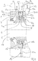
- Fig. 1 shows a section of a turbomachine in the area of a sealing system 1, which serves to seal a rotor 2 of the turbomachine from a stator 3 of the turbomachine.
- the sealing system 1 is positioned between the rotor 2 and the stator 3.
- the sealing system 1 has at least one rotor-side component 4a, 4b rotating with the rotor 2 and at least one stator-side component 5a, 5b which is fixed together with the stator 3.
- the sealing system 1 has at least one dry gas seal 6, the dry gas seal 6 having a rotor-side seal component 7 and one has stator-side sealing component 8, which are compressed in the axial direction via a spring element 9, which is accommodated in a stator-side spring chamber 10 and which presses against the stator-side sealing element 8.
- a sealing gap 11 is formed between these compressed sealing components 7, 8 of the dry gas seal 6.
- the rotor-side sealing component 7 of the dry gas seal 6 is fastened to the rotor-side component 4a of the sealing system 1.
- a stator-side guide element 16 guides the stator-side sealing element 8.
- An optional labyrinth seal 17 is formed between the stator-side component 5a in the exemplary embodiment shown.
- At least one seal gas supply channel 12 and at least one seal gas discharge channel 13 are introduced into the stator 3 and into at least one stator-side component that is fixed together with the stator 3.
- the preferred exemplary embodiment shown is formed by a plurality of sections, namely by a radially outer section 12a, which is introduced into the stator 3, and in a plurality of radially inner sections 12b, which are introduced into the adjacent, stator-side component 5a, preferably an annular gap is formed between the stator 3 and this adjoining stator-side component 5a, via which the section 12a is coupled to the sections 12b.
- the sealing gas discharge duct 13 is formed in an analogous manner, the sealing gas discharge duct 13 having a radially outer section 13a which is introduced into the stator 3, and a plurality of radially inner sections 13b which are introduced into the adjacent stator-side component 5b .
- An annular gap is preferably formed between the stator 3 and the adjacent stator-side component 5b, via which the radially inner sections 13b of the sealing gas outflow channel 13 are connected to the radially outer section 13a thereof.
- the sealing gas can be guided in the direction of the sealing gap 11 to be sealed via the sealing gas supply channel 12, the sealing gas being able to be discharged downstream of this sealing gap 11 from the sealing gap 11 via the sealing gas discharge channel 13.
- the flow arrow A visualizes the supply of the sealing gas (see black arrowhead) via the sealing gas supply channel 12.
- the sealing system 1 of the turbomachine has a cleaning device, by means of which liquid detergent can preferably be guided in the direction of the spring element 9 or the spring chamber 10 receiving the spring element 9 and / or in the direction of the sealing gap 11, in order to in the area of the spring element 9 and / or of the sealing gap 11 to clean the sealing system 11 and thus to remove contaminants therefrom, so that the risk of the drying gas seal 6 of the sealing system 1 failing due to contamination is reduced.
- This cleaning device comprises a detergent supply duct 14 and a detergent discharge duct 15.
- the detergent supply duct 14, and preferably also the detergent is in the stator 3 and in a stator-side component 5b which is adjacent to the stator 3 and is fixed together with the stator 3 -Discharge duct 15 introduced.
- Detergent can be guided in the direction of the spring element 9 or the spring chamber 10 via the detergent supply channel 14, and preferably also be fed from the spring chamber 10 via a gap 18 between the stator-side sealing component 8 and the stator-side component 5b to the sealing gap 11, whereby liquid detergent, which cleans the spring chamber 10, is discharged from the spring chamber 10 via the detergent discharge duct 15, and detergent which reaches the area of the sealing gap 11 can be discharged via the sealing gas discharge duct 13.
- the detergent is distributed in the spring chamber 10 over the entire circumference thereof.
- the flow arrow C illustrates the guidance of the detergent (see white arrowhead), which flows from the detergent supply channel 14 via the spring chamber 10 in the direction of the detergent discharge channel 15.
- a flow arrow B visualizes the flow of the detergent and the sealing gas (see black and white filled arrowhead) starting from the sealing gap 11 into the area of the sealing gas outflow channel 13.
- the sealing gas supply channel 12 is axially spaced from the sealing gas discharge channel 13, but they are preferably formed at the same circumferential position.
- the detergent supply channel 14 and the detergent discharge channel 15 are offset from one another in the circumferential direction and are preferably formed in the axial direction at the same axial position.
- Fig. 1 shows that the detergent supply channel 14 is formed in the axial direction between the sealing gas supply channel 12 and the sealing gas discharge channel 13, and is preferably formed together with the same at the same circumferential position.
- the detergent supply channel 14 is formed by a radially outer section 14a, which is introduced into the stator 3, and by at least one radially inner sections 14b, which are introduced into the stator-side component 5b.
- This stator-side component 5b likewise provides the detergent discharge channel 15, namely at least one radially inner section 15b thereof, a radially outer section 15a of the detergent discharge channel 15 in turn being provided by the stator 3.
- both the sealing gas and the liquid detergent can be optimally guided, and with optimum use of space.
- the sealing system 1 also has a detergent dosing system, not shown, via which the detergent can be provided to the detergent supply channel 14. It is possible for the detergent dosing system to comprise a detergent tank in which detergent is provided, it being possible to connect a separate pressure container to the detergent tank, which pressurizes the detergent in the detergent storage container and provides the detergent supply line 14 with a defined detergent pressure.
- Detergent can also be provided starting from the detergent storage container of the detergent supply line 14 via a pump, the delivery pressure of which then determines the detergent pressure.
- the sealing system namely the detergent dosing system, not shown, preferably comprises a heating device, not shown, in order to heat the detergent in the direction of the sealing system 1 before it is supplied.
- a turbomachine which comprises the sealing system 1 described above is preferably cleaned with the detergent when the turbomachine is at a standstill, so that the detergent is then fed to the sealing system 1, namely the dry gas seal 6, only when the turbomachine is at a standstill.
- heating the detergent is advantageous in order to heat the sealing system 1, namely the dry gas seal 6, when the turbomachine is at a standstill and to prevent process gas condensation during standstill, that is to say during cleaning.
- the pressure level of the detergent is of course designed to determine whether the cleaning of the sealing system 1 is carried out with the turbomachine stationary or running.
Landscapes
- Engineering & Computer Science (AREA)
- General Engineering & Computer Science (AREA)
- Mechanical Engineering (AREA)
- Physics & Mathematics (AREA)
- Thermal Sciences (AREA)
- Sealing Using Fluids, Sealing Without Contact, And Removal Of Oil (AREA)
- Structures Of Non-Positive Displacement Pumps (AREA)
- Turbine Rotor Nozzle Sealing (AREA)
Description
- Die Erfindung betrifft eine Strömungsmaschine mit einem Dichtungssystem gemäß dem Oberbergriff des Anspruchs 1. Des Weiteren betrifft die Erfindung ein Verfahren zum Reinigen des Dichtungssystems.
- In Strömungsmaschinen, wie zum Beispiel in Turbokompressoren, kommen zur Abdichtung eines Rotors der Strömungsmaschine gegenüber einem Stator der Strömungsmaschine mehrheitlich Trockengasdichtungen zum Einsatz.
- So ist aus der
EP 2 977 563 A1 eine Trockendichtung einer Strömungsmaschine bekannt. Dichtungsgas kann einem abzudichtenden Dichtspalt über eine Bohrung im Stator sowie über einen Gasraum, der von der Trockengasdichtung bereitgestellt wird, zugeführt werden. - Bei Trockengasdichtungen besteht das Problem, dass dieselben durch Verschmutzungen ausfallen können. Solche Verschmutzungen werden dabei zum Beispiel über im Dichtungsgas und/oder Prozessgas enthaltene Fremdstoffe eingetragen. Die Verschmutzungen können sich dabei durch auskondensierende Gase, auskondensierende Feststoffe oder andere Fremdpartikel ausbilden, welche sich im Bereich der Trockengasdichtung ablagern können und zu einem Versagen der Trockengasdichtung führen können. Dies ist von Nachteil.
- Die
DE 10 2015 013 659 A1 offenbart eine Strömungsmaschine gemäß dem Oberbergriff des Anspruchs 1. -
- Der hier vorliegenden Erfindung liegt die Aufgabe zugrunde, eine Strömungsmaschine mit einem Dichtungssystem bereitzustellen, bei dem die Gefahr eines verschmutzungsbedingten Ausfalls reduziert ist. Weiterhin liegt der Erfindung die Aufgabe zugrunde, ein Verfahren zum Reinigen des Dichtungssystems bereitzustellen.
- Diese Aufgabe wird durch eine Strömungsmaschine nach Anspruch 1 gelöst.
- Über die Reinigungseinrichtung ist Waschmittel in Richtung auf das Federelement zur Reinigung desselben und/oder in Richtung auf den Dichtspalt zur Reinigung desselben führbar. Über die Reinigungseinrichtung kann Waschmittel zur Reinigung der Trockengasdichtung bereitgestellt werden, nämlich zur Reinigung des Federelements bzw. eines das Federelement aufnehmenden Federraum s und/oder zur Reinigung des Dichtspalts der Trockengasdichtung. Durch die Reinigung besteht eine geringere Gefahr, dass das Dichtungssystem verschmutzungsbedingt ausfällt.
- In den Stator und in eine erste zusammen mit dem Stator feststehende, statorseitige Komponente mindestens ein Dichtgas-Zuführkanal und mindestens ein Dichtgas-Abführkanal eingebracht, um über den Dichtgas-Zuführkanal Dichtgas in Richtung auf den Dichtspalt der Trockengasdichtung und über den Dichtgas-Abführkanal Dichtgas weg vom Dichtspalt der Trockengasdichtung zu führen. Der Dichtgas-Zuführkanal und der Dichtgas-Abführkanal sind in Axialrichtung beabstandet. Ein Waschmittel-Zuführkanal ist in Axialrichtung zwischen dem Dichtgas-Zuführkanal und dem Dichtgas-Abführkanal ausgebildet.
- Vorzugsweise sind in den Stator ein radial äußerer Abschnitt des Dichtgas-Zuführkanals und in die angrenzende statorseitigen Komponente mehrere radial innere Abschnitte des Dichtgas-Zuführkanals eingebracht, wobei vorzugsweise zwischen dem Stator und der angrenzenden statorseitigen Komponente ein diese Abschnitte verbindender erster Ringspalt ausgebildet ist. Hiermit kann das Dichtgas besonders vorteilhaft innerhalb des Dichtungssystems geführt werden.
- Nach einer vorteilhaften Weiterbildung ist in den Stator und in eine zweite zusammen mit dem Stator feststehende, statorseitige Komponente mindestens ein Waschmittel-Zuführkanal und mindestens ein Waschmittel-Abführkanal eingebracht, um über den Waschmittel-Zuführkanal Waschmittel in Richtung auf das Federelement und über den Waschmittel-Abführkanal Waschmittel weg vom das Federelement zu führen. Vorzugsweise sind in den Stator ein radial äußerer Abschnitt des Waschmittel-Zuführkanals und in die angrenzende statorseitigen Komponente ein radial innerer Abschnitt des Waschmittel-Zuführkanals eingebracht. Vorzugsweise ist Waschmittel über den Waschmittel-Zuführkanal auch in Richtung auf den Dichtspalt und über den Dichtgas-Abführkanal weg vom Dichtspalt führbar. Hierdurch kann das Waschmittel besonders vorteilhaft innerhalb des Dichtungssystems geführt werden.
- Nach einer vorteilhaften Weiterbildung sind der Dichtgas-Zuführkanal und der Dichtgas-Abführkanal in Axialrichtung vorzugsweise an derselben Umfangsposition ausgebildet. Der Waschmittel-Zuführkanal und der Waschmittel-Abführkanal sind in Umfangsrichtung beabstandet und vorzugsweise an derselben Axialposition ausgebildet. Der Waschmittel-Zuführkanal ist vorzugsweise an derselben Umfangsposition ausgebildet. Diese Weiterbildung erlaubt eine besonders vorteilhafte, funktional optimale sowie bauraumsparende Integration der Zuführkanäle für Dichtgas und Waschmittel in das Dichtungssystem.
- Nach einer vorteilhaften Weiterbildung weist das Dichtungssystem der Strömungsmaschine ein Waschmitteldosiersystem auf, über welches das Waschmittel dem Waschmittel-Zuführkanal mit einem definierten Waschmitteldruck zuführbar ist. Durch Bereitstellung des definierten Waschmitteldrucks kann ein optimales Reinigungsergebnis der Trockengasdichtung gewährleistet werden.
- Vorzugsweise weist das Dichtungssystem der Strömungsmaschine, insbesondere das Waschmitteldosiersystem, eine Heizeinrichtung zum Erhitzen des Waschmittels auf. Durch das Erhitzen des Waschmittels kann das Dichtungssystem erhitzt werden, was insbesondere dann von Vorteil ist, wenn das Reinigen des Dichtungssystems während des Stillstands der Strömungsmaschine erfolgt.
- Das Verfahren zum Reinigen des Dichtungssystems ist in Anspruch 13 definiert.
- Bevorzugte Weiterbildungen der Erfindung ergeben sich aus den Unteransprüchen und der nachfolgenden Beschreibung. Ausführungsbeispiele der Erfindung werden, ohne hierauf beschränkt zu sein, an Hand der Zeichnung näher erläutert. Dabei zeigt:
- Fig. 1:
- einen schematisieren Axialschnitt durch eine erfindungsgemäße Strömungsmaschine im Bereich eines Dichtungssystems.
- Die Erfindung betrifft eine Strömungsmaschine, insbesondere einen Turbokompressors welcher der Verdichtung eines Prozessgases dient, mit einem Dichtungssystem.
-
Fig. 1 zeigt einen Ausschnitt aus einer Strömungsmaschine im Bereich eines Dichtungssystems 1, welches der Abdichtung eines Rotors 2 der Strömungsmaschine gegenüber einem Stator 3 der Strömungsmaschine dient. Zwischen dem Rotor 2 und dem Stator 3 ist das Dichtungssystem 1 positioniert. Das Dichtungssystem 1 verfügt über mindestens eine mit dem Rotor 2 rotierende, rotorseitige Komponente 4a, 4b sowie über mindestens eine zusammen mit dem Stator 3 feststehende, statorseitige Komponente 5a, 5b. - Das Dichtungssystem 1 verfügt über mindestens eine Trockengasdichtung 6, wobei die Trockengasdichtung 6 eine rotorseitige Dichtungskomponente 7 und eine statorseitige Dichtungskomponente 8 aufweist, die in Axialrichtung über ein Federelement 9, das in einem statorseitigen Federraum 10 aufgenommen ist und das gegen das statorseitige Dichtungselement 8 drückt, zusammengedrückt sind. Zwischen diesen zusammengedrückten Dichtungskomponenten 7, 8 der Trockengasdichtung 6 ist ein Dichtspalt 11 ausgebildet. Die rotorseitige Dichtungskomponente 7 der Trockengasdichtung 6 ist an der rotorseitigen Komponente 4a des Dichtungssystems 1 befestigt. Ein statorseitiges Führungselement 16 führt das statorseitige Dichtungselement 8. Zwischen der statorseitigen Komponente 5a ist im gezeigten Ausführungsbeispiel eine optionale Labyrinthdichtung 17 ausgebildet.
- In den Stator 3 und in mindestens eine zusammen mit dem Stator 3 feststehende statorseitige Komponente ist mindestens ein Dichtgas-Zuführkanal 12 sowie mindestens ein Dichtgas-Abführkanal 13 eingebracht.
- Im in
Fig. 1 gezeigten, bevorzugten Ausführungsbeispiel ist der Abgaszuführkanal 12 durch mehrere Abschnitte ausgebildet, nämlich durch einen radial äußeren Abschnitt 12a, der in den Stator 3 eingebracht ist, sowie in mehrere radial innere Abschnitte 12b, die in die angrenzende, statorseitige Komponente 5a eingebracht sind, wobei vorzugsweise zwischen dem Stator 3 und dieser angrenzenden statorseitigen Komponente 5a ein Ringspalt ausgebildet ist, über welchen der Abschnitt 12a mit den Abschnitten 12b gekoppelt ist. Auf analoge Art und Weise ist der Dichtgas-Abführkanal 13 ausgebildet, wobei der Dichtgas-Abführkanal 13 einen radial äußeren Abschnitt 13a aufweist, der in den Stator 3 eingebracht ist, sowie mehrere radial innere Abschnitte 13b, die in die angrenzende statorseitige Komponente 5b eingebracht sind. Zwischen dem Stator 3 und der angrenzenden statorseitigen Komponente 5b ist vorzugsweise ein Ringspalt ausgebildet, über den die radial inneren Abschnitte 13b des Dichtgas-Abströmkanals 13 mit dem radial äußeren Abschnitt 13a desselben verbunden sind. - Über den Dichtgas-Zuführkanal 12 ist das Dichtgas in Richtung auf den abzudichtenden Dichtspalt 11 führbar, wobei das Dichtgas stromabwärts dieses Dichtspalts 11 vom Dichtspalt 11 über den Dichtgas-Abführkanal 13 abführbar ist.
- Der Strömungspfeil A visualisiert die Zuführung des Dichtgases (siehe schwarz ausgefüllte Pfeilspitze) über den Dichtgas-Zuführkanal 12.
- Das Dichtungssystem 1 der Strömungsmaschine verfügt über eine Reinigungseinrichtung, über die vorzugsweise flüssiges Waschmittel in Richtung auf das Federelement 9 bzw. den das Federelement 9 aufnehmenden Federraum 10 und/oder in Richtung auf den Dichtspalt 11 führbar ist, um im Bereich des Federelements 9 und/oder des Dichtspalts 11 das Dichtungssystem 11 zu reinigen und so Verschmutzungen aus demselben auszutragen, sodass die Gefahr des verschmutzungsbedingten Ausfalls der Trockengasdichtung 6 des Dichtungssystems 1 reduziert ist.
- Diese Reinigungseinrichtung umfasst einen Waschmittel-Zuführkanal 14 und einen Waschmittel-Abführkanal 15. In den Stator 3 sowie in eine sich an den Stator 3 angrenzende, zusammen mit dem Stator 3 feststehende, statorseitige Komponente 5b ist der Waschmittel-Zuführkanal 14 sowie vorzugsweise auch der Waschmittel-Abführkanal 15 eingebracht. Über den Waschmittel-Zuführkanal 14 kann Waschmittel in Richtung auf das Federelement 9 bzw. den Federraum 10 geführt werden, und vorzugsweise auch ausgehend vom Federraum 10 über einen Spalt 18 zwischen der statorseitige Dichtungskomponente 8 und der statorseitige Komponente 5b dem Dichtspalt 11 zugeführt werden, wobei flüssiges Waschmittel, welches den Federraum 10 reinigt, über den Waschmittel-Abführkanal 15 vom Federraum 10 abgeführt wird, und wobei Waschmittel, welches in den Bereich des Dichtspalts 11 gelangt, über den Dichtgas-Abführkanal 13 abgeführt werden kann. Das Waschmittel verteilt sich im Federraum 10 über den gesamten Umfang desselben.
- Der Strömungspfeil C verdeutlicht die Führung des Waschmittels (siehe weiß ausgefüllte Pfeilspitze), welches ausgehend vom Waschmittel-Zuführkanal 14 über den Federraum 10 in Richtung auf den Waschmittel-Abführkanal 15 strömt.
- Ein Strömungspfeil B visualisiert die Strömung des Waschmittels und des Dichtgases (siehe schwarz/weiß ausgefüllte Pfeilspitze) ausgehend vom Dichtspalt 11 in den Bereich des Dichtgas-Abströmkanals 13.
- Der Dichtgas-Zuführkanal 12 ist vom Dichtgas-Abführkanal 13 axial beabstandet, vorzugsweise sind dieselben jedoch an der gleichen Umfangsposition ausgebildet. Der Waschmittel-Zuführkanal 14 und der Waschmittel-Abführkanal 15 sind in Umfangsrichtung gesehen zueinander versetzt und in Axialrichtung vorzugsweise an derselben Axialposition ausgebildet.
Fig. 1 zeigt, dass der Waschmittel-Zuführkanal 14 dabei in Axialrichtung gesehen zwischen dem Dichtgas-Zuführkanal 12 und dem Dichtgas-Abführkanal 13 ausgebildet ist, und vorzugsweise zusammen mit denselben an derselben Umfangsposition ausgebildet ist. - Der Waschmittel-Zuführkanal 14 ist von einem radial äußeren Abschnitt 14a, der in den Stator 3 eingebracht ist, sowie von mindestens einem radial inneren Abschnitten 14b ausgebildet, die in die statorseitige Komponente 5b eingebracht sind. Ebenso stellt diese statorseitige Komponente 5b den Waschmittel-Abführkanal 15 bereit, nämlich mindestens einen radial inneren Abschnitte 15b desselben, wobei ein radial äußerer Abschnitt 15a des Waschmittel-Abführkanals 15 wiederum vom Stator 3 bereitgestellt ist.
- Mit der oben beschriebenen Ausführung des Dichtungssystems 1 kann sowohl das Dichtgas als auch das flüssige Waschmittel optimal geführt werden, und zwar unter optimaler Bauraumausnutzung.
- Das Dichtungssystem 1 verfügt weiterhin über ein nicht gezeigtes WaschmittelDosiersystem, über welches das Waschmittel dem Waschmittel-Zuführkanal 14 bereitgestellt werden kann. Hierbei ist es möglich, dass das Waschmitteldosiersystem einen Waschmitteltank umfasst, in dem Waschmittel bereitgestellt wird, wobei an den Waschmitteltank ein separater Druckbehälter angeschlossen werden kann, der das Waschmittel im Waschmittelvorratsbehälter unter Druck setzt und mit einem definierten Waschmitteldruck der Waschmittel-Zuführleitung 14 bereitstellt.
- Ebenso ist es möglich, die Funktion von Waschmittelvorratsbehälter und Druckluftbehälter in einem Behälter zu integrieren und im Druckmittelbehälter unter Druck stehendes Waschmittel bereitzustellen und dasselbe dann ausgehend vom Druckmittelbehälter mit einem definierten Waschmitteldruck der Waschmittel-Zuführleitung 14 zuzuführen.
- Auch kann Waschmittel ausgehend vom Waschmittelvorratsbehälter der Waschmittel-Zuführleitung 14 über eine Pumpe bereitgestellt werden, deren Förderdruck dann den Waschmitteldruck bestimmt.
- Vorzugsweise umfasst das Dichtungssystem, nämlich das nicht gezeigte Waschmitteldosiersystem, eine nicht gezeigte Heizeinrichtung, um das Waschmittel vor der Zuführung desselben in Richtung auf das Dichtungssystem 1 zu erhitzen.
- Eine Strömungsmaschine, die das oben beschriebene Dichtungssystem 1 umfasst, wird vorzugsweise im Stillstand der Strömungsmaschine mithilfe des Waschmittels gereinigt, sodass dann das Waschmittel ausschließlich im Stillstand der Strömungsmaschine dem Dichtungssystem 1, nämlich der Trockengasdichtung 6, zugeführt wird. In diesem Fall ist das Erhitzen des Waschmittels von Vorteil, um bei stillstehender Strömungsmaschine das Dichtungssystem 1, nämlich der Trockengasdichtung 6, zu erhitzen und eine Prozessgaskondensation während des Stillstands, also während der Reinigung, zu verhindern.
- Es ist jedoch auch möglich, das Dichtungssystem 1 bei laufender Strömungsmaschine zu reinigen, wobei dann bei laufender Strömungsmaschine gleichzeitig Dichtgas und Waschmittel in Richtung auf das Dichtungssystem 1 geführt wird.
- Das Druckniveau des Waschmittels ist selbstverständlich darauf ausgelegt, ob das Reinigen des Dichtungssystems 1 bei stillstehender oder laufender Strömungsmaschine durchgeführt wird.
-
- 1
- Dichtungssystem
- 2
- Rotor
- 3
- Stator
- 4a
- rotorseitige Komponente
- 4b
- rotorseitige Komponente
- 5a
- statorseitige Komponente
- 5b
- statorseitige Komponente
- 6
- Trockengasdichtung
- 7
- rotorseitige Dichtungskomponente
- 8
- statorseitige Dichtungskomponente
- 9
- Feder
- 10
- Federraum
- 11
- Dichtspalt
- 12
- Dichtgas-Zuführkanal
- 12a
- Abschnitt
- 12b
- Abschnitt
- 13
- Dichtgas-Abführkanal
- 13a
- Abschnitt
- 13b
- Abschnitt
- 14
- Waschmittel-Zuführkanal
- 14a
- Abschnitt
- 14b
- Abschnitt
- 15
- Waschmittel-Abführkanal
- 15a
- Abschnitt
- 15b
- Abschnitt
- 16
- Führungselement
- 17
- Labyrinthdichtung
- 18
- Spalt
Claims (14)
- Strömungsmaschine mit einem Dichtungssystem (1) zur Abdichtung eines Rotors (2) der Strömungsmaschine gegenüber einem Stator (3) der Strömungsmaschine,mit mindestens einer zusammen mit dem Rotor (2) rotierenden, rotorseitigen Komponente (4a, 4b),mit mindestens einer mit zusammen mit dem Stator (3) feststehenden, statorseitigen Komponente (5a, 5b),mit mindestens einer Trockengasdichtung (6), die eine rotorseitige Dichtungskomponente (7) und eine statorseitige Dichtungskomponente (8) aufweist, die über ein Federelement (9) unter Ausbildung eines Dichtspalts (11) zusammengedrückt sind,mit einer Reinigungseinrichtung,wobeiin den Stator (3) und in zusammen mit dem Stator (3) feststehende, statorseitige Komponenten (5a, 5b) ein Dichtgas-Zuführkanal (12) und ein Dichtgas-Abführkanal (13) eingebracht ist, um über den Dichtgas-Zuführkanal (12) Dichtgas in Richtung auf den Dichtspalt (11) und über den Dichtgas-Abführkanal (13) Dichtgas weg vom Dichtspalt (11) zu führen, wobei der Dichtgas-Zuführkanal (12) und der Dichtgas-Abführkanal (13) in Axialrichtung beabstandet sind,dadurch gekennzeichnet, dass über die Reinigungseinrichtung Waschmittel in Richtung auf das Federelement (9) zur Reinigung desselben und/oder in Richtung auf den Dichtspalt (11) zur Reinigung desselben führbar ist,wobei ein Waschmittel-Zuführkanal (14) in Axialrichtung zwischen dem Dichtgas-Zuführkanal (12) und dem Dichtgas-Abführkanal (13) ausgebildet ist.
- Strömungsmaschine mit einem Dichtungssystem (1) nach Anspruch 1, dadurch gekennzeichnet, dass in den Stator (3) ein radial äußerer Abschnitt (12a) des Dichtgas-Zuführkanals (12) und in die angrenzende statorseitigen Komponente (5a) mehrere radial innere Abschnitte (12b) des Dichtgas-Zuführkanals (12) eingebracht sind, wobei vorzugsweise zwischen dem Stator (3) und der angrenzenden statorseitigen Komponente (5a) ein diese Abschnitte (12a, 12b) verbindender erster Ringspalt ausgebildet ist.
- Strömungsmaschine mit einem Dichtungssystem (1) nach Anspruch 1 oder 2, dadurch gekennzeichnet, dass in den Stator (3) ein radial äußerer Abschnitt (13a) des Dichtgas-Abführkanals (13) und in die angrenzende statorseitigen Komponente (5b) mehrere radial innere Abschnitte (13b) des Dichtgas-Abführkanals (12) eingebracht sind, wobei vorzugsweise zwischen dem Stator (3) und der angrenzenden statorseitigen Komponente (5b) ein diese Abschnitte (13a, 13b) verbindender Ringspalt ausgebildet ist.
- Strömungsmaschine mit einem Dichtungssystem (1) nach einem der Ansprüche 1 bis 3, dadurch gekennzeichnet, dass in den Stator (3) und in eine zusammen mit dem Stator (3) feststehende statorseitige Komponente (5b) der Waschmittel-Zuführkanal (14) und ein Waschmittel-Abführkanal (15) eingebracht ist, um über den Waschmittel-Zuführkanal (14) Waschmittel in Richtung auf das Federelement (9) und über den Waschmittel-Abführkanal (15) Waschmittel weg vom das Federelement (9) zu führen.
- Strömungsmaschine mit einem Dichtungssystem (1) nach Anspruch 4, dadurch gekennzeichnet, dass in den Stator (3) ein radial äußerer Abschnitt (14a, 15a) des Waschmittel-Zuführkanals (14) und des Waschmittel-Abführkanals (15) eingebracht ist, und dass in die angrenzende statorseitigen Komponente (5b) ein radial innerer Abschnitt (14a) des Waschmittel-Zuführkanals (14) und ein radial innerer Abschnitte (15a) des Waschmittel-Abführkanals (15) eingebracht ist.
- Strömungsmaschine mit einem Dichtungssystem (1) nach Anspruch 4 oder 6, dadurch gekennzeichnet, dass Waschmittel über den Waschmittel-Zuführkanal (14) in Richtung auf den Dichtspalt (11) und über den Dichtgas-Abführkanal (13) weg vom Dichtspalt (11) führbar ist.
- Strömungsmaschine mit einem Dichtungssystem (1) nach einem der Ansprüche 1 bis 6, dadurch gekennzeichnet, dass der Dichtgas-Zuführkanal (12) und der Dichtgas-Abführkanal (13) an derselben Umfangsposition ausgebildet sind.
- Strömungsmaschine mit einem Dichtungssystem (1) nach einem der Ansprüche 4 7 8, dadurch gekennzeichnet, dass der Waschmittel Zuführkanal (14) und der Waschmittel-Abführkanal (15) in Umfangsrichtung beabstandet und vorzugsweise an derselben Axialposition ausgebildet sind.
- Strömungsmaschine mit einem Dichtungssystem (1) nach einem der Ansprüche 4 bis 8, dadurch gekennzeichnet, dass der Waschmittel-Zuführkanal (14) an derselben Umfangsposition wie der Dichtgas-Zuführkanal (12) und der Dichtgas-Abführkanal (13) ausgebildet ist.
- Strömungsmaschine mit einem Dichtungssystem (1) nach einem der Ansprüche 4 bis 9, dadurch gekennzeichnet, dass das Waschmittel dem Waschmittel-Zuführkanal (14) ausgehend von einem Waschmitteldosiersystem mit einem definierten Waschmitteldruck zuführbar ist.
- Strömungsmaschine mit einem Dichtungssystem (1) nach einem der Ansprüche 1 bis 10, gekennzeichnet durch eine Heizeinrichtung zum Erhitzen des zur Reinigung der Trockengasdichtung genutzten Waschmittels.
- Turbokompressor zur Verdichtung eines Prozessgases, mit einem Stator und einem Rotor, und mit einem Dichtungssystem (1), dadurch gekennzeichnet, dass das Dichtungssystem (1) nach einem der Ansprüche 1 bis 11 ausgebildet ist.
- Verfahren zum Reinigen eines Turbokompressors nach Anspruch 12, wobei die Trockengasdichtung im Stillstand der Strömungsmaschine gereinigt wird.
- Verfahren nach Anspruch 13, dadurch gekennzeichnet, dass das Waschmittel vor der Zuführung in Richtung auf den Dichtspalt erhitzt wird.
Applications Claiming Priority (1)
| Application Number | Priority Date | Filing Date | Title |
|---|---|---|---|
| DE102017109663.9A DE102017109663A1 (de) | 2017-05-05 | 2017-05-05 | Dichtungssystem, Strömungsmaschine mit einem Dichtungssystem und Verfahren zum Reinigen desselben |
Publications (2)
| Publication Number | Publication Date |
|---|---|
| EP3399154A1 EP3399154A1 (de) | 2018-11-07 |
| EP3399154B1 true EP3399154B1 (de) | 2020-07-22 |
Family
ID=62017218
Family Applications (1)
| Application Number | Title | Priority Date | Filing Date |
|---|---|---|---|
| EP18167723.8A Active EP3399154B1 (de) | 2017-05-05 | 2018-04-17 | Dichtungssystem, strömungsmaschine mit einem dichtungssystem und verfahren zum reinigen desselben |
Country Status (6)
| Country | Link |
|---|---|
| US (1) | US11434930B2 (de) |
| EP (1) | EP3399154B1 (de) |
| JP (1) | JP7053365B2 (de) |
| KR (1) | KR102353784B1 (de) |
| CN (1) | CN108799189B (de) |
| DE (1) | DE102017109663A1 (de) |
Families Citing this family (2)
| Publication number | Priority date | Publication date | Assignee | Title |
|---|---|---|---|---|
| US10968762B2 (en) * | 2018-11-19 | 2021-04-06 | General Electric Company | Seal assembly for a turbo machine |
| CN115435087A (zh) * | 2021-06-02 | 2022-12-06 | 德莱赛稳公司 | 轴密封装置 |
Family Cites Families (25)
| Publication number | Priority date | Publication date | Assignee | Title |
|---|---|---|---|---|
| JPS5810616B2 (ja) | 1979-04-04 | 1983-02-26 | 株式会社日立製作所 | メカニカルシ−ル |
| US5492341A (en) * | 1990-07-17 | 1996-02-20 | John Crane Inc. | Non-contacting, gap-type seal having a ring with a patterned seal face |
| US5529315A (en) * | 1994-02-14 | 1996-06-25 | John Crane Inc. | Tandem seal arrangement for mechanical face seals |
| EP0972910B1 (de) * | 1998-07-14 | 2003-06-11 | ALSTOM (Switzerland) Ltd | Berührungsloses Abdichten von Spalten in Gasturbinen |
| JP4111698B2 (ja) * | 2001-08-31 | 2008-07-02 | イーグル工業株式会社 | メカニカルシール装置 |
| DE10236471C2 (de) * | 2001-11-07 | 2003-10-16 | Siemens Ag | Magnetische Lagerung einer Rotorwelle gegen einen Stator unter Verwendung eines Hoch-T¶c¶-Supraleiters |
| GB0202839D0 (en) | 2002-02-07 | 2002-03-27 | Johnson Electric Sa | Blower motor |
| CN101031745B (zh) * | 2004-08-26 | 2010-05-26 | 伊格尔工业股份有限公司 | 机械密封装置 |
| JP4730086B2 (ja) | 2005-12-26 | 2011-07-20 | 株式会社デンソー | 渦流式ブロワ装置 |
| WO2008013147A1 (en) * | 2006-07-25 | 2008-01-31 | Eagle Industry Co., Ltd. | Mechanical seal device |
| CN201137598Y (zh) | 2007-12-24 | 2008-10-22 | 上海东方泵业(集团)有限公司 | 泵用双端面机械密封冲洗液恒压装置 |
| WO2009143213A2 (en) * | 2008-05-21 | 2009-11-26 | John Crane Inc. | Seal monitoring and control system |
| CN102112785B (zh) * | 2009-09-24 | 2014-12-03 | 伊格尔工业股份有限公司 | 机械密封件 |
| DE102011007071A1 (de) * | 2011-04-08 | 2012-10-11 | Siemens Aktiengesellschaft | Wellendichtungseinsatz |
| JP5927072B2 (ja) * | 2012-07-17 | 2016-05-25 | 日本ピラー工業株式会社 | メカニカルシール |
| KR20150086309A (ko) * | 2012-11-20 | 2015-07-27 | 뉴 웨이 머신 컴포넌츠, 인코포레이티드 | 시일로 사용하기 위한 공기 베어링 |
| CN103925233A (zh) | 2013-01-16 | 2014-07-16 | 宝山钢铁股份有限公司 | 乳化液提升泵机械式密封的自循环冷却的方法及装置 |
| US9567554B2 (en) * | 2014-01-10 | 2017-02-14 | General Electric Company | Apparatus, method, and solvent for cleaning turbine components |
| CN203978859U (zh) | 2014-06-11 | 2014-12-03 | 大连帝国屏蔽电泵有限公司 | 一种自吸式泥浆密封型屏蔽泵 |
| DE102014011042A1 (de) * | 2014-07-26 | 2016-01-28 | Man Diesel & Turbo Se | Strömungsmaschine |
| EP3186487A1 (de) * | 2014-08-28 | 2017-07-05 | Turboden S.p.A. | Dichtungsanordnung in einer turbine und verfahren zur begrenzung von betriebsflüssigkeit |
| WO2016207761A1 (en) * | 2015-06-23 | 2016-12-29 | Turboden S.R.L. | Seal arrangement in a turbine and method for confining the operating fluid |
| DE102015013659A1 (de) * | 2015-10-22 | 2017-04-27 | Man Diesel & Turbo Se | Trockengasdichtungssystem und Strömungsmaschine mit einem Trockengasdichtungssystem |
| CN105351244B (zh) * | 2015-11-24 | 2017-08-25 | 青海盐湖工业股份有限公司 | 串联式干气密封装置及其在轻烃泵上的应用和使用方法 |
| US10428673B2 (en) * | 2016-05-02 | 2019-10-01 | General Electric Company | Aspirating face seal assembly and a method of operating the same |
-
2017
- 2017-05-05 DE DE102017109663.9A patent/DE102017109663A1/de not_active Withdrawn
-
2018
- 2018-04-17 EP EP18167723.8A patent/EP3399154B1/de active Active
- 2018-05-02 JP JP2018088740A patent/JP7053365B2/ja active Active
- 2018-05-02 KR KR1020180050617A patent/KR102353784B1/ko active Active
- 2018-05-03 US US15/970,625 patent/US11434930B2/en active Active
- 2018-05-04 CN CN201810419654.6A patent/CN108799189B/zh active Active
Non-Patent Citations (1)
| Title |
|---|
| None * |
Also Published As
| Publication number | Publication date |
|---|---|
| US11434930B2 (en) | 2022-09-06 |
| DE102017109663A1 (de) | 2018-11-08 |
| KR102353784B1 (ko) | 2022-01-19 |
| JP7053365B2 (ja) | 2022-04-12 |
| US20180320710A1 (en) | 2018-11-08 |
| JP2018189090A (ja) | 2018-11-29 |
| EP3399154A1 (de) | 2018-11-07 |
| CN108799189A (zh) | 2018-11-13 |
| KR20180122952A (ko) | 2018-11-14 |
| CN108799189B (zh) | 2021-04-02 |
Similar Documents
| Publication | Publication Date | Title |
|---|---|---|
| EP2071131B1 (de) | Abdichtung mindestens einer Welle mit mindestens einer hydraulischen Dichtung | |
| EP3091179B1 (de) | Rotoranordnung für eine strömungsmaschine und verdichter | |
| AT503578A4 (de) | Dichtanordnung | |
| WO2008155267A1 (de) | Turbolader von einem fahrzeug mit einer spezifischen dichtungsanordnung | |
| EP2886211B1 (de) | Maschine mit fliegend gelagertem Rotor | |
| EP3365532B1 (de) | Trockengasdichtungssystem und strömungsmaschine mit einem trockengasdichtungssystem | |
| EP3140572A1 (de) | Gleitringdichtungsanordnung mit verbesserter gasabscheidung | |
| EP3267089A1 (de) | Ölverteilungssystem und turbomaschine mit einem ölverteilungssystem | |
| EP3399154A1 (de) | Dichtungssystem, strömungsmaschine mit einem dichtungssystem und verfahren zum reinigen desselben | |
| EP2824289A1 (de) | Vorrichtung und Verfahren zum Ableiten von Sperrluft in einem Turbofan-Triebwerk sowie zugehöriges Turbofan-Triebwerk | |
| DE102012023727B4 (de) | Schmiermitteleinrichtung für ein Wälzlager | |
| DE102017207173B4 (de) | Turbolader mit Sollbruchstelle für eine Brennkraftmaschine | |
| EP3495639A1 (de) | Verdichtermodul für eine strömungsmaschine und zugehörige verdichteranordnung | |
| WO2019007886A1 (de) | Vollmantel-schneckenzentrifuge | |
| EP0844367A1 (de) | Geschweisster Rotor einer Strömungsmaschine | |
| WO2004089559A1 (de) | Vorrichtung zur rückführung von öl in walzenlagern | |
| DE102017114646B4 (de) | Förder- und Verdichterelement, Hohlwelle, Verbrennungsmotor und Verfahren zum Reinigen von Blowby-Gasen | |
| DE102009035895A1 (de) | Drehbar gelagertes Filterelement zur Ölabscheidung | |
| EP3374602B1 (de) | Vorrichtung zur abdichtung eines lagergehäuses und abgasturbolader mit einer solchen vorrichtung | |
| EP2085575A1 (de) | Kombination von Bürstendichtung mit Kolbenring für grosse Dichtspalte | |
| WO2015086160A1 (de) | Verdichter | |
| DE102016004770B4 (de) | Anschlaganordnung, Ansaug- und Abgasanlage und Fahrzeug umfassend solch eine Anlage | |
| DE102015211103B4 (de) | Ölreinigungseinrichtung einer Brennkraftmaschine | |
| DE102013005431B4 (de) | Axialströmungsmaschine | |
| DE102007016425A1 (de) | Ölabscheider für CO2-Kälteanlagen |
Legal Events
| Date | Code | Title | Description |
|---|---|---|---|
| PUAI | Public reference made under article 153(3) epc to a published international application that has entered the european phase |
Free format text: ORIGINAL CODE: 0009012 |
|
| STAA | Information on the status of an ep patent application or granted ep patent |
Free format text: STATUS: THE APPLICATION HAS BEEN PUBLISHED |
|
| AK | Designated contracting states |
Kind code of ref document: A1 Designated state(s): AL AT BE BG CH CY CZ DE DK EE ES FI FR GB GR HR HU IE IS IT LI LT LU LV MC MK MT NL NO PL PT RO RS SE SI SK SM TR |
|
| AX | Request for extension of the european patent |
Extension state: BA ME |
|
| RAP1 | Party data changed (applicant data changed or rights of an application transferred) |
Owner name: MAN ENERGY SOLUTIONS SE |
|
| STAA | Information on the status of an ep patent application or granted ep patent |
Free format text: STATUS: REQUEST FOR EXAMINATION WAS MADE |
|
| 17P | Request for examination filed |
Effective date: 20190326 |
|
| RBV | Designated contracting states (corrected) |
Designated state(s): AL AT BE BG CH CY CZ DE DK EE ES FI FR GB GR HR HU IE IS IT LI LT LU LV MC MK MT NL NO PL PT RO RS SE SI SK SM TR |
|
| STAA | Information on the status of an ep patent application or granted ep patent |
Free format text: STATUS: EXAMINATION IS IN PROGRESS |
|
| 17Q | First examination report despatched |
Effective date: 20190807 |
|
| GRAP | Despatch of communication of intention to grant a patent |
Free format text: ORIGINAL CODE: EPIDOSNIGR1 |
|
| STAA | Information on the status of an ep patent application or granted ep patent |
Free format text: STATUS: GRANT OF PATENT IS INTENDED |
|
| RIC1 | Information provided on ipc code assigned before grant |
Ipc: F16J 15/34 20060101ALI20200217BHEP Ipc: F01D 11/04 20060101ALI20200217BHEP Ipc: F01D 25/00 20060101ALI20200217BHEP Ipc: F01D 11/00 20060101AFI20200217BHEP |
|
| INTG | Intention to grant announced |
Effective date: 20200325 |
|
| GRAS | Grant fee paid |
Free format text: ORIGINAL CODE: EPIDOSNIGR3 |
|
| GRAA | (expected) grant |
Free format text: ORIGINAL CODE: 0009210 |
|
| STAA | Information on the status of an ep patent application or granted ep patent |
Free format text: STATUS: THE PATENT HAS BEEN GRANTED |
|
| AK | Designated contracting states |
Kind code of ref document: B1 Designated state(s): AL AT BE BG CH CY CZ DE DK EE ES FI FR GB GR HR HU IE IS IT LI LT LU LV MC MK MT NL NO PL PT RO RS SE SI SK SM TR |
|
| REG | Reference to a national code |
Ref country code: GB Ref legal event code: FG4D Free format text: NOT ENGLISH |
|
| REG | Reference to a national code |
Ref country code: CH Ref legal event code: EP |
|
| REG | Reference to a national code |
Ref country code: DE Ref legal event code: R096 Ref document number: 502018001921 Country of ref document: DE |
|
| REG | Reference to a national code |
Ref country code: CH Ref legal event code: NV Representative=s name: E. BLUM AND CO. AG PATENT- UND MARKENANWAELTE , CH |
|
| REG | Reference to a national code |
Ref country code: AT Ref legal event code: REF Ref document number: 1293568 Country of ref document: AT Kind code of ref document: T Effective date: 20200815 |
|
| REG | Reference to a national code |
Ref country code: IE Ref legal event code: FG4D Free format text: LANGUAGE OF EP DOCUMENT: GERMAN |
|
| REG | Reference to a national code |
Ref country code: LT Ref legal event code: MG4D |
|
| PG25 | Lapsed in a contracting state [announced via postgrant information from national office to epo] |
Ref country code: PT Free format text: LAPSE BECAUSE OF FAILURE TO SUBMIT A TRANSLATION OF THE DESCRIPTION OR TO PAY THE FEE WITHIN THE PRESCRIBED TIME-LIMIT Effective date: 20201123 Ref country code: FI Free format text: LAPSE BECAUSE OF FAILURE TO SUBMIT A TRANSLATION OF THE DESCRIPTION OR TO PAY THE FEE WITHIN THE PRESCRIBED TIME-LIMIT Effective date: 20200722 Ref country code: LT Free format text: LAPSE BECAUSE OF FAILURE TO SUBMIT A TRANSLATION OF THE DESCRIPTION OR TO PAY THE FEE WITHIN THE PRESCRIBED TIME-LIMIT Effective date: 20200722 Ref country code: BG Free format text: LAPSE BECAUSE OF FAILURE TO SUBMIT A TRANSLATION OF THE DESCRIPTION OR TO PAY THE FEE WITHIN THE PRESCRIBED TIME-LIMIT Effective date: 20201022 Ref country code: NO Free format text: LAPSE BECAUSE OF FAILURE TO SUBMIT A TRANSLATION OF THE DESCRIPTION OR TO PAY THE FEE WITHIN THE PRESCRIBED TIME-LIMIT Effective date: 20201022 Ref country code: ES Free format text: LAPSE BECAUSE OF FAILURE TO SUBMIT A TRANSLATION OF THE DESCRIPTION OR TO PAY THE FEE WITHIN THE PRESCRIBED TIME-LIMIT Effective date: 20200722 Ref country code: GR Free format text: LAPSE BECAUSE OF FAILURE TO SUBMIT A TRANSLATION OF THE DESCRIPTION OR TO PAY THE FEE WITHIN THE PRESCRIBED TIME-LIMIT Effective date: 20201023 Ref country code: SE Free format text: LAPSE BECAUSE OF FAILURE TO SUBMIT A TRANSLATION OF THE DESCRIPTION OR TO PAY THE FEE WITHIN THE PRESCRIBED TIME-LIMIT Effective date: 20200722 Ref country code: HR Free format text: LAPSE BECAUSE OF FAILURE TO SUBMIT A TRANSLATION OF THE DESCRIPTION OR TO PAY THE FEE WITHIN THE PRESCRIBED TIME-LIMIT Effective date: 20200722 |
|
| PG25 | Lapsed in a contracting state [announced via postgrant information from national office to epo] |
Ref country code: PL Free format text: LAPSE BECAUSE OF FAILURE TO SUBMIT A TRANSLATION OF THE DESCRIPTION OR TO PAY THE FEE WITHIN THE PRESCRIBED TIME-LIMIT Effective date: 20200722 Ref country code: RS Free format text: LAPSE BECAUSE OF FAILURE TO SUBMIT A TRANSLATION OF THE DESCRIPTION OR TO PAY THE FEE WITHIN THE PRESCRIBED TIME-LIMIT Effective date: 20200722 Ref country code: LV Free format text: LAPSE BECAUSE OF FAILURE TO SUBMIT A TRANSLATION OF THE DESCRIPTION OR TO PAY THE FEE WITHIN THE PRESCRIBED TIME-LIMIT Effective date: 20200722 Ref country code: IS Free format text: LAPSE BECAUSE OF FAILURE TO SUBMIT A TRANSLATION OF THE DESCRIPTION OR TO PAY THE FEE WITHIN THE PRESCRIBED TIME-LIMIT Effective date: 20201122 |
|
| PG25 | Lapsed in a contracting state [announced via postgrant information from national office to epo] |
Ref country code: NL Free format text: LAPSE BECAUSE OF FAILURE TO SUBMIT A TRANSLATION OF THE DESCRIPTION OR TO PAY THE FEE WITHIN THE PRESCRIBED TIME-LIMIT Effective date: 20200722 |
|
| REG | Reference to a national code |
Ref country code: DE Ref legal event code: R097 Ref document number: 502018001921 Country of ref document: DE |
|
| PG25 | Lapsed in a contracting state [announced via postgrant information from national office to epo] |
Ref country code: SM Free format text: LAPSE BECAUSE OF FAILURE TO SUBMIT A TRANSLATION OF THE DESCRIPTION OR TO PAY THE FEE WITHIN THE PRESCRIBED TIME-LIMIT Effective date: 20200722 Ref country code: RO Free format text: LAPSE BECAUSE OF FAILURE TO SUBMIT A TRANSLATION OF THE DESCRIPTION OR TO PAY THE FEE WITHIN THE PRESCRIBED TIME-LIMIT Effective date: 20200722 Ref country code: DK Free format text: LAPSE BECAUSE OF FAILURE TO SUBMIT A TRANSLATION OF THE DESCRIPTION OR TO PAY THE FEE WITHIN THE PRESCRIBED TIME-LIMIT Effective date: 20200722 Ref country code: CZ Free format text: LAPSE BECAUSE OF FAILURE TO SUBMIT A TRANSLATION OF THE DESCRIPTION OR TO PAY THE FEE WITHIN THE PRESCRIBED TIME-LIMIT Effective date: 20200722 Ref country code: EE Free format text: LAPSE BECAUSE OF FAILURE TO SUBMIT A TRANSLATION OF THE DESCRIPTION OR TO PAY THE FEE WITHIN THE PRESCRIBED TIME-LIMIT Effective date: 20200722 |
|
| PLBE | No opposition filed within time limit |
Free format text: ORIGINAL CODE: 0009261 |
|
| STAA | Information on the status of an ep patent application or granted ep patent |
Free format text: STATUS: NO OPPOSITION FILED WITHIN TIME LIMIT |
|
| PG25 | Lapsed in a contracting state [announced via postgrant information from national office to epo] |
Ref country code: AL Free format text: LAPSE BECAUSE OF FAILURE TO SUBMIT A TRANSLATION OF THE DESCRIPTION OR TO PAY THE FEE WITHIN THE PRESCRIBED TIME-LIMIT Effective date: 20200722 |
|
| 26N | No opposition filed |
Effective date: 20210423 |
|
| PG25 | Lapsed in a contracting state [announced via postgrant information from national office to epo] |
Ref country code: SK Free format text: LAPSE BECAUSE OF FAILURE TO SUBMIT A TRANSLATION OF THE DESCRIPTION OR TO PAY THE FEE WITHIN THE PRESCRIBED TIME-LIMIT Effective date: 20200722 |
|
| PG25 | Lapsed in a contracting state [announced via postgrant information from national office to epo] |
Ref country code: SI Free format text: LAPSE BECAUSE OF FAILURE TO SUBMIT A TRANSLATION OF THE DESCRIPTION OR TO PAY THE FEE WITHIN THE PRESCRIBED TIME-LIMIT Effective date: 20200722 |
|
| REG | Reference to a national code |
Ref country code: NL Ref legal event code: MP Effective date: 20200722 |
|
| PG25 | Lapsed in a contracting state [announced via postgrant information from national office to epo] |
Ref country code: MC Free format text: LAPSE BECAUSE OF FAILURE TO SUBMIT A TRANSLATION OF THE DESCRIPTION OR TO PAY THE FEE WITHIN THE PRESCRIBED TIME-LIMIT Effective date: 20200722 |
|
| PG25 | Lapsed in a contracting state [announced via postgrant information from national office to epo] |
Ref country code: LU Free format text: LAPSE BECAUSE OF NON-PAYMENT OF DUE FEES Effective date: 20210417 |
|
| REG | Reference to a national code |
Ref country code: BE Ref legal event code: MM Effective date: 20210430 |
|
| PG25 | Lapsed in a contracting state [announced via postgrant information from national office to epo] |
Ref country code: IE Free format text: LAPSE BECAUSE OF NON-PAYMENT OF DUE FEES Effective date: 20210417 |
|
| PG25 | Lapsed in a contracting state [announced via postgrant information from national office to epo] |
Ref country code: IS Free format text: LAPSE BECAUSE OF FAILURE TO SUBMIT A TRANSLATION OF THE DESCRIPTION OR TO PAY THE FEE WITHIN THE PRESCRIBED TIME-LIMIT Effective date: 20201122 |
|
| PG25 | Lapsed in a contracting state [announced via postgrant information from national office to epo] |
Ref country code: BE Free format text: LAPSE BECAUSE OF NON-PAYMENT OF DUE FEES Effective date: 20210430 |
|
| REG | Reference to a national code |
Ref country code: DE Ref legal event code: R081 Ref document number: 502018001921 Country of ref document: DE Owner name: MAN ENERGY SOLUTIONS SE, DE Free format text: FORMER OWNER: MAN ENERGY SOLUTIONS SE, 86153 AUGSBURG, DE Ref country code: DE Ref legal event code: R081 Ref document number: 502018001921 Country of ref document: DE Owner name: EAGLEBURGMANN GERMANY GMBH & CO. KG, DE Free format text: FORMER OWNER: MAN ENERGY SOLUTIONS SE, 86153 AUGSBURG, DE Ref country code: DE Ref legal event code: R081 Ref document number: 502018001921 Country of ref document: DE Owner name: EVERLLENCE SE, DE Free format text: FORMER OWNER: MAN ENERGY SOLUTIONS SE, 86153 AUGSBURG, DE |
|
| REG | Reference to a national code |
Ref country code: GB Ref legal event code: 732E Free format text: REGISTERED BETWEEN 20221110 AND 20221116 |
|
| PG25 | Lapsed in a contracting state [announced via postgrant information from national office to epo] |
Ref country code: CY Free format text: LAPSE BECAUSE OF FAILURE TO SUBMIT A TRANSLATION OF THE DESCRIPTION OR TO PAY THE FEE WITHIN THE PRESCRIBED TIME-LIMIT Effective date: 20200722 |
|
| PG25 | Lapsed in a contracting state [announced via postgrant information from national office to epo] |
Ref country code: HU Free format text: LAPSE BECAUSE OF FAILURE TO SUBMIT A TRANSLATION OF THE DESCRIPTION OR TO PAY THE FEE WITHIN THE PRESCRIBED TIME-LIMIT; INVALID AB INITIO Effective date: 20180417 |
|
| PG25 | Lapsed in a contracting state [announced via postgrant information from national office to epo] |
Ref country code: MK Free format text: LAPSE BECAUSE OF FAILURE TO SUBMIT A TRANSLATION OF THE DESCRIPTION OR TO PAY THE FEE WITHIN THE PRESCRIBED TIME-LIMIT Effective date: 20200722 |
|
| REG | Reference to a national code |
Ref country code: AT Ref legal event code: PC Ref document number: 1293568 Country of ref document: AT Kind code of ref document: T Owner name: EAGLEBURGMANN GERMANY GMBH & CO. KG, DE Effective date: 20240416 Ref country code: AT Ref legal event code: PC Ref document number: 1293568 Country of ref document: AT Kind code of ref document: T Owner name: MAN ENERGY SOLUTIONS SE, DE Effective date: 20240416 |
|
| PG25 | Lapsed in a contracting state [announced via postgrant information from national office to epo] |
Ref country code: MT Free format text: LAPSE BECAUSE OF FAILURE TO SUBMIT A TRANSLATION OF THE DESCRIPTION OR TO PAY THE FEE WITHIN THE PRESCRIBED TIME-LIMIT Effective date: 20200722 |
|
| PGFP | Annual fee paid to national office [announced via postgrant information from national office to epo] |
Ref country code: DE Payment date: 20250422 Year of fee payment: 8 |
|
| PGFP | Annual fee paid to national office [announced via postgrant information from national office to epo] |
Ref country code: IT Payment date: 20250424 Year of fee payment: 8 |
|
| PGFP | Annual fee paid to national office [announced via postgrant information from national office to epo] |
Ref country code: FR Payment date: 20250425 Year of fee payment: 8 |
|
| PGFP | Annual fee paid to national office [announced via postgrant information from national office to epo] |
Ref country code: CH Payment date: 20250501 Year of fee payment: 8 |
|
| PGFP | Annual fee paid to national office [announced via postgrant information from national office to epo] |
Ref country code: AT Payment date: 20250423 Year of fee payment: 8 |
|
| REG | Reference to a national code |
Ref country code: DE Ref legal event code: R081 Ref document number: 502018001921 Country of ref document: DE Owner name: EAGLEBURGMANN GERMANY GMBH & CO. KG, DE Free format text: FORMER OWNERS: EAGLEBURGMANN GERMANY GMBH & CO. KG, 82515 WOLFRATSHAUSEN, DE; MAN ENERGY SOLUTIONS SE, 86153 AUGSBURG, DE Ref country code: DE Ref legal event code: R081 Ref document number: 502018001921 Country of ref document: DE Owner name: EVERLLENCE SE, DE Free format text: FORMER OWNERS: EAGLEBURGMANN GERMANY GMBH & CO. KG, 82515 WOLFRATSHAUSEN, DE; MAN ENERGY SOLUTIONS SE, 86153 AUGSBURG, DE |
|
| PG25 | Lapsed in a contracting state [announced via postgrant information from national office to epo] |
Ref country code: TR Free format text: LAPSE BECAUSE OF FAILURE TO SUBMIT A TRANSLATION OF THE DESCRIPTION OR TO PAY THE FEE WITHIN THE PRESCRIBED TIME-LIMIT Effective date: 20200722 |
|
| PGFP | Annual fee paid to national office [announced via postgrant information from national office to epo] |
Ref country code: GB Payment date: 20260324 Year of fee payment: 9 |
|
| REG | Reference to a national code |
Ref country code: AT Ref legal event code: HC Ref document number: 1293568 Country of ref document: AT Kind code of ref document: T Owner name: EVERLLENCE SE, DE Effective date: 20260223 Ref country code: AT Ref legal event code: HC Ref document number: 1293568 Country of ref document: AT Kind code of ref document: T Owner name: EAGLEBURGMANN GERMANY GMBH & CO. KG, DE Effective date: 20260223 |
|
| REG | Reference to a national code |
Ref country code: CH Ref legal event code: U11 Free format text: ST27 STATUS EVENT CODE: U-0-0-U10-U11 (AS PROVIDED BY THE NATIONAL OFFICE) Effective date: 20260501 |