EP3398894A1 - Elevator system and counterweight screen - Google Patents
Elevator system and counterweight screen Download PDFInfo
- Publication number
- EP3398894A1 EP3398894A1 EP17169717.0A EP17169717A EP3398894A1 EP 3398894 A1 EP3398894 A1 EP 3398894A1 EP 17169717 A EP17169717 A EP 17169717A EP 3398894 A1 EP3398894 A1 EP 3398894A1
- Authority
- EP
- European Patent Office
- Prior art keywords
- elevator system
- counterweight
- face skin
- core
- screen
- Prior art date
- Legal status (The legal status is an assumption and is not a legal conclusion. Google has not performed a legal analysis and makes no representation as to the accuracy of the status listed.)
- Granted
Links
Images


Classifications
-
- B—PERFORMING OPERATIONS; TRANSPORTING
- B66—HOISTING; LIFTING; HAULING
- B66B—ELEVATORS; ESCALATORS OR MOVING WALKWAYS
- B66B5/00—Applications of checking, fault-correcting, or safety devices in elevators
- B66B5/0043—Devices enhancing safety during maintenance
- B66B5/005—Safety of maintenance personnel
- B66B5/0056—Safety of maintenance personnel by preventing crushing
-
- B—PERFORMING OPERATIONS; TRANSPORTING
- B66—HOISTING; LIFTING; HAULING
- B66B—ELEVATORS; ESCALATORS OR MOVING WALKWAYS
- B66B17/00—Hoistway equipment
- B66B17/12—Counterpoises
-
- B—PERFORMING OPERATIONS; TRANSPORTING
- B66—HOISTING; LIFTING; HAULING
- B66B—ELEVATORS; ESCALATORS OR MOVING WALKWAYS
- B66B11/00—Main component parts of lifts in, or associated with, buildings or other structures
- B66B11/0005—Constructional features of hoistways
Definitions
- the present invention relates to an elevator system.
- the present invention also relates to a counterweight screen.
- an elevator system comprising a shaft having a pit.
- a car is guided by a pair of first guide rails to be vertically movable in the shaft.
- a counterweight is connected to the car by a suspension rope.
- the counterweight is guided by a pair of second guide rails to be vertically movable in the shaft.
- a counterweight screen is arranged in a space between the counterweight and the car.
- the counterweight screen is attached to the second guide rails at the pit.
- the counterweight screen is a protective safety cover which is supposed to guard the path of the counterweight and to prevent any object from entering into the path of the counterweight.
- a pit is the part of the shaft situated below the lowest landing served by the car.
- New elevator standards EN 81-20 and EN 81-50 set requirements for stiffness of the counterweight screen. With a 300 N static force exerted to the counterweight screen it is not allowed to bend so much that it can touch the counterweight.
- the standard EN 81-21 sets reduced requirements for clearances. With higher counterweight screen stiffness requirements together with reduced clearances set problem for the technical solution.
- Counterweight screens have been typically made from sheet metal material. Stiffness of the counterweight screen has been increased with bends or with pressed or roll formed grooves. A problem is that increasing stiffness in counterweight screen material increases also weight and costs of the counterweight screen. Additional weight impacts problems in installation and maintenance. Also separate stiffeners, such as stiffening profiles or flat stiffeners, have been used which have been glued or riveted to the screen plate.
- stiffness is increased by separate stiffeners (profiles of flat sheet metals typically fixed by glue or rivets), both weight and cost will increase too much. Also, this solution is taking too much space for reduced clearance between car and counterweight.
- stiffness is increased by stiffening forms (pressed or roll formed) total thickness impacts problems with reduced clearance. Also with lower volume, pressing tooling cost is increasing too high.
- the objective of the invention is to alleviate the disadvantages mentioned above.
- the present invention provides an elevator system comprising a shaft having a pit, a car guided by a pair of first guide rails to be vertically movable in the shaft, a counterweight connected to the car by a suspension rope, the counterweight being guided by a pair of second guide rails to be vertically movable in the shaft, and a counterweight screen arranged in a space between the counterweight and the car, the counterweight screen being attached to the second guide rails at the pit.
- the counterweight screen is a sandwich-structured composite panel.
- the technical effect of the invention is that that it provides a light-weight counterweight screen which is feasible for installation and maintenance.
- a wide counterweight with required large counterweight screen size can have good stiffness and weight/total thickness ratio enabling reduced clearance between car and counterweight, especially with wide counterweights, where it is difficult to reduce bending of the counterweight screen.
- the invention provides a cost efficient way to implement a thin counterweight screen with high stiffness.
- the sandwich-structured composite panel of the counterweight screen comprises a first face skin, a second face skin, and a core arranged between the first face skin and the second face skin, the first and second face skins being attached to the core.
- the first face skin is sheet metal and/or the second face skin is sheet metal.
- the first face skin is steel sheet metal and/or the second face skin is steel sheet metal.
- the first face skin is aluminum sheet metal and/or the second face skin is aluminum sheet metal.
- the first face skin is a polymer sheet and/or the second face skin is a polymer sheet.
- the first face skin is a non-metallic fibre reinforced polymer matrix sheet and/or the second face skin is a non-metallic fibre reinforced polymer matrix sheet.
- the core is a honeycomb structure.
- the honeycomb structure of the core is made of metal.
- the honeycomb structure of the core is made of polymer.
- the core is a micro lattice structure.
- Micro lattice structure is composed of a network of interconnecting struts.
- the micro lattice structure of the core is made of metal.
- the micro lattice structure of the core is made of polymer.
- the core is a solid or foam sheet of polymer or polyurethane.
- the core is a metallic foam structure.
- the metallic foam structure of the core is made of aluminum.
- the counterweight screen is designed to withstand a force of 300 N over the area of 5 cm 2 without deflecting into the path of the counterweight, said force being a force which a person may be expected to exert to the counterweight screen.
- the counterweight screen has a thickness less than 6 mm.
- the present invention provides a counterweight screen.
- the counterweight screen is a sandwich-structured composite panel.
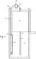
- the elevator system comprises a shaft 1. Part of the shaft 1 situated below the lowest landing served by a car 2 is a pit 2. The car 3 is guided by a pair of first guide rails 4 to be vertically movable in the shaft. A counterweight 5 is connected to the car 3 by a suspension rope 6. The suspension rope 6 runs over a traction wheel 12 driven by a hoisting machine 13. The counterweight 5 is guided by a pair of second guide rails 7 to be vertically movable in the shaft 1.
- a counterweight screen 8 is arranged at the pit 2 in a space between the counterweight 5 and the car 3. The counterweight screen 8 is attached to the second guide rails 7. The counterweight screen 8 is a sandwich-structured composite panel.
- the counterweight screen 8 is designed to withstand a force of 300 N over the area of 5 cm 2 without deflecting into the path of the counterweight 5.
- the force of 300 N is a force which a person may be expected to exert to the counterweight screen in accordance with standard EN- 81-20.
- the counterweight screen 8 has a thickness less than 6 mm.
- Figure 3 to 5 illustrate the sandwich-structured composite panel of the counterweight screen 8.
- the sandwich-structured composite panel comprises a first face skin 9, a second face skin 10, and a core 11 arranged between the first face skin 9 and the second face skin, 10 the first and second face skins 9, 10 being attached to the core 11.
- the first face skin 9 may be sheet metal and/or the second face skin 10 may be sheet metal.
- the first face skin 9 may be steel sheet metal and/or the second face skin 10 may be steel sheet metal.
- the first face skin 9 may be aluminum sheet metal and/or the second face skin 10 may be aluminum sheet metal.
- the first face skin 9 may be a polymer sheet and/or the second face skin 10 may be a polymer sheet.
- the first face skin 9 may be a non-metallic fibre reinforced polymer matrix sheet and/or the second face skin 10 may be a non-metallic fibre reinforced polymer matrix sheet.
- Non-metallic fibre may be e.g. glass, carbon or aramid fibre.
- Fibre reinforcement may be a mat, weave, short fiber or continuous fiber unidirectional type of reinforcement.
- Figure 3 shows a cross-section of the counterweight screen 8 wherein the core 11 between the first face skin 9 and the second face skin 10 is a honeycomb structure.
- the honeycomb structure of the core 11 may be made of metal or polymer.
- Figure 4 shows a cross-section of the counterweight screen 8 wherein the core 11 between the first face skin 9 and the second face skin 10 is a micro lattice structure.
- the micro lattice structure of the core 11 may be made of metal or polymer.
- Figure 5 shows a cross-section of the counterweight screen 8 wherein the core 11 between the first face skin 9 and the second face skin 10 is a solid sheet made of polymer.
- the core 11 may be a sheet of polymer foam or polyurethane foam.
- Figure 6 shows a cross-section of the counterweight screen 8 wherein the core 11 between the first face skin 9 and the second face skin 10 is a metallic foam structure.
- the metallic foam structure of the core 11 may be made of aluminum.
Landscapes
- Cage And Drive Apparatuses For Elevators (AREA)
Abstract
Description
- The present invention relates to an elevator system. The present invention also relates to a counterweight screen.
- In prior art is known an elevator system comprising a shaft having a pit. A car is guided by a pair of first guide rails to be vertically movable in the shaft. A counterweight is connected to the car by a suspension rope. The counterweight is guided by a pair of second guide rails to be vertically movable in the shaft. A counterweight screen is arranged in a space between the counterweight and the car. The counterweight screen is attached to the second guide rails at the pit. The counterweight screen is a protective safety cover which is supposed to guard the path of the counterweight and to prevent any object from entering into the path of the counterweight. By definition, a pit is the part of the shaft situated below the lowest landing served by the car. New elevator standards EN 81-20 and EN 81-50 set requirements for stiffness of the counterweight screen. With a 300 N static force exerted to the counterweight screen it is not allowed to bend so much that it can touch the counterweight. The standard EN 81-21 sets reduced requirements for clearances. With higher counterweight screen stiffness requirements together with reduced clearances set problem for the technical solution. Counterweight screens have been typically made from sheet metal material. Stiffness of the counterweight screen has been increased with bends or with pressed or roll formed grooves. A problem is that increasing stiffness in counterweight screen material increases also weight and costs of the counterweight screen. Additional weight impacts problems in installation and maintenance. Also separate stiffeners, such as stiffening profiles or flat stiffeners, have been used which have been glued or riveted to the screen plate. If stiffness is increased by separate stiffeners (profiles of flat sheet metals typically fixed by glue or rivets), both weight and cost will increase too much. Also, this solution is taking too much space for reduced clearance between car and counterweight. When stiffness is increased by stiffening forms (pressed or roll formed) total thickness impacts problems with reduced clearance. Also with lower volume, pressing tooling cost is increasing too high.
- The objective of the invention is to alleviate the disadvantages mentioned above.
- In particular, it is an objective of the present invention to provide a light-weight counterweight screen which can have a small thickness with good stiffness.
- According to a first aspect, the present invention provides an elevator system comprising a shaft having a pit, a car guided by a pair of first guide rails to be vertically movable in the shaft, a counterweight connected to the car by a suspension rope, the counterweight being guided by a pair of second guide rails to be vertically movable in the shaft, and a counterweight screen arranged in a space between the counterweight and the car, the counterweight screen being attached to the second guide rails at the pit. According to the invention the counterweight screen is a sandwich-structured composite panel.
- The technical effect of the invention is that that it provides a light-weight counterweight screen which is feasible for installation and maintenance. A wide counterweight with required large counterweight screen size can have good stiffness and weight/total thickness ratio enabling reduced clearance between car and counterweight, especially with wide counterweights, where it is difficult to reduce bending of the counterweight screen. The invention provides a cost efficient way to implement a thin counterweight screen with high stiffness.
- In an embodiment of the elevator system, the sandwich-structured composite panel of the counterweight screen comprises a first face skin, a second face skin, and a core arranged between the first face skin and the second face skin, the first and second face skins being attached to the core.
- In an embodiment of the elevator system, the first face skin is sheet metal and/or the second face skin is sheet metal.
- In an embodiment of the elevator system, the first face skin is steel sheet metal and/or the second face skin is steel sheet metal.
- In an embodiment of the elevator system, the first face skin is aluminum sheet metal and/or the second face skin is aluminum sheet metal.
- In an embodiment of the elevator system, the first face skin is a polymer sheet and/or the second face skin is a polymer sheet.
- In an embodiment of the elevator system, the first face skin is a non-metallic fibre reinforced polymer matrix sheet and/or the second face skin is a non-metallic fibre reinforced polymer matrix sheet.
- In an embodiment of the elevator system, the core is a honeycomb structure.
- In an embodiment of the elevator system, the honeycomb structure of the core is made of metal.
- In an embodiment of the elevator system, the honeycomb structure of the core is made of polymer.
- In an embodiment of the elevator system, the core is a micro lattice structure. Micro lattice structure is composed of a network of interconnecting struts.
- In an embodiment of the elevator system, the micro lattice structure of the core is made of metal.
- In an embodiment of the elevator system, the micro lattice structure of the core is made of polymer.
- In an embodiment of the elevator system, the core is a solid or foam sheet of polymer or polyurethane.
- In an embodiment of the elevator system, the core is a metallic foam structure.
- In an embodiment of the elevator system, the metallic foam structure of the core is made of aluminum.
- In an embodiment of the elevator system, the counterweight screen is designed to withstand a force of 300 N over the area of 5 cm2 without deflecting into the path of the counterweight, said force being a force which a person may be expected to exert to the counterweight screen.
- In an embodiment of the elevator system, the counterweight screen has a thickness less than 6 mm.
- According to a second aspect, the present invention provides a counterweight screen. According to the invention the counterweight screen is a sandwich-structured composite panel.
- It is to be understood that the aspects and embodiments of the invention described above may be used in any combination with each other. Several of the aspects and embodiments may be combined together to form a further embodiment of the invention.
- The accompanying drawings, which are included to provide a further understanding of the invention and constitute a part of this specification, illustrate embodiments of the invention and together with the description help to explain the principles of the invention. In the drawings:
-
Figure 1 schematically shows an elevator system according to one embodiment of the invention, -
Figure 2 is an axonometric view of the pit of the shaft of the elevator system according to one embodiment of the invention, -
Figure 3 is a cross-section of the counterweight screen according to first embodiment of the invention, -
Figure 4 is a cross-section of the counterweight screen according to second embodiment of the invention, -
Figure 5 is a cross-section of the counterweight screen according to third embodiment of the invention, and -
Figure 6 is a cross-section of the counterweight screen according to fourth embodiment of the invention. - Referring to
Figures 1 and2 , the elevator system comprises ashaft 1. Part of theshaft 1 situated below the lowest landing served by acar 2 is apit 2. Thecar 3 is guided by a pair offirst guide rails 4 to be vertically movable in the shaft. Acounterweight 5 is connected to thecar 3 by a suspension rope 6. The suspension rope 6 runs over atraction wheel 12 driven by a hoistingmachine 13. Thecounterweight 5 is guided by a pair ofsecond guide rails 7 to be vertically movable in theshaft 1. Acounterweight screen 8 is arranged at thepit 2 in a space between thecounterweight 5 and thecar 3. Thecounterweight screen 8 is attached to the second guide rails 7. Thecounterweight screen 8 is a sandwich-structured composite panel. As can be seen inFigure 2 , some equipment which may require maintenance is located in thepit 2. Therefore, a maintenance person may be required to enter thepit 2. Thecounterweight screen 8 is designed to withstand a force of 300 N over the area of 5 cm2 without deflecting into the path of thecounterweight 5. The force of 300 N is a force which a person may be expected to exert to the counterweight screen in accordance with standard EN- 81-20. Preferably thecounterweight screen 8 has a thickness less than 6 mm. -
Figure 3 to 5 illustrate the sandwich-structured composite panel of thecounterweight screen 8. The sandwich-structured composite panel comprises afirst face skin 9, asecond face skin 10, and a core 11 arranged between thefirst face skin 9 and the second face skin, 10 the first and second face skins 9, 10 being attached to thecore 11. Thefirst face skin 9 may be sheet metal and/or thesecond face skin 10 may be sheet metal. For example, thefirst face skin 9 may be steel sheet metal and/or thesecond face skin 10 may be steel sheet metal. In another example thefirst face skin 9 may be aluminum sheet metal and/or thesecond face skin 10 may be aluminum sheet metal. Alternatively, thefirst face skin 9 may be a polymer sheet and/or thesecond face skin 10 may be a polymer sheet. For example, thefirst face skin 9 may be a non-metallic fibre reinforced polymer matrix sheet and/or thesecond face skin 10 may be a non-metallic fibre reinforced polymer matrix sheet. Non-metallic fibre may be e.g. glass, carbon or aramid fibre. Fibre reinforcement may be a mat, weave, short fiber or continuous fiber unidirectional type of reinforcement. -
Figure 3 shows a cross-section of thecounterweight screen 8 wherein the core 11 between thefirst face skin 9 and thesecond face skin 10 is a honeycomb structure. The honeycomb structure of the core 11 may be made of metal or polymer. -
Figure 4 shows a cross-section of thecounterweight screen 8 wherein the core 11 between thefirst face skin 9 and thesecond face skin 10 is a micro lattice structure. The micro lattice structure of the core 11 may be made of metal or polymer. -
Figure 5 shows a cross-section of thecounterweight screen 8 wherein the core 11 between thefirst face skin 9 and thesecond face skin 10 is a solid sheet made of polymer. In an embodiment the core 11 may be a sheet of polymer foam or polyurethane foam. -
Figure 6 shows a cross-section of thecounterweight screen 8 wherein the core 11 between thefirst face skin 9 and thesecond face skin 10 is a metallic foam structure. The metallic foam structure of the core 11 may be made of aluminum. - Although the invention has been the described in conjunction with a certain type of elevator system, it should be understood that the invention is not limited to any certain type of elevator system. While the present inventions have been described in connection with a number of exemplary embodiments, and implementations, the present inventions are not so limited, but rather cover various modifications, and equivalent arrangements, which fall within the purview of prospective claims.
Claims (19)
- An elevator system comprisinga shaft (1) having a pit (2),a car (3) guided by a pair of first guide rails (4) to be vertically movable in the shaft,a counterweight (5) connected to the car by a suspension rope (6), the counterweight being guided by a pair of second guide rails (7) to be vertically movable in the shaft, anda counterweight screen (8) arranged in a space between the counterweight (5) and the car (3), the counterweight screen (8) being attached to the second guide rails (7) at the pit (2), characterized in that the counterweight screen (8) is a sandwich-structured composite panel.
- An elevator system according to claim 1, characterized in that the sandwich-structured composite panel of the counterweight screen (8) comprisesa first face skin (9),a second face skin (10), anda core (11) arranged between the first face skin (9) and the second face skin (10) the first and second face skins (9, 10) being attached to the core (11).
- An elevator system according to claim 1 or 2, characterized in that the first face skin (9) is sheet metal and/or the second face skin (10) is sheet metal.
- An elevator system according to claim 3, characterized in that the first face skin (9) is steel sheet metal and/or the second face skin (10) is steel sheet metal.
- An elevator system according to claim 3, characterized in that the first face skin (9) is aluminum sheet metal and/or the second face skin (10) is aluminum sheet metal.
- An elevator system according to claim 1 or 2, characterized in that the first face skin (9) is a polymer sheet and/or the second face skin (10) is a polymer sheet.
- An elevator system according to claim 6, characterized in that the first face skin (9) is a non-metallic fibre reinforced polymer matrix sheet and/or the second face skin (10) is a non-metallic fibre reinforced polymer matrix sheet.
- An elevator system according to any one of the claims 1 to 7, characterized in that the core (11) is a honeycomb structure.
- An elevator system according to claim 8, characterized in that the honeycomb structure of the core (11) is made of metal.
- An elevator system according to claim 8, characterized in that the honeycomb structure of the core (11) is made of polymer.
- An elevator system according to any one of the claims 1 to 7, characterized in that the core (11) is a micro lattice structure.
- An elevator system according to claim 11, characterized in that the micro lattice structure of the core (11) is made of metal.
- An elevator system according to claim 11, characterized in that the micro lattice structure of the core (11) is made of polymer.
- An elevator system according to any one of the claims 1 to 7, characterized in that the core (11) is a solid or foam sheet of polymer or polyurethane.
- An elevator system according to any one of the claims 1 to 7, characterized in that the core (11) is a metallic foam structure.
- An elevator system according to claim 15, characterized in that the metallic foam structure of the core (11) is made of aluminum.
- An elevator system according to any one of the claims 1 to 16, characterized in that the counterweight screen (8) is designed to withstand a force of 300 N over the area of 5 cm2 without deflecting into the path of the counterweight (5), said force being a force which a person may be expected to exert to the counterweight screen.
- An elevator system according to any one of the claims 1 to 15, characterized in that the counterweight screen (8) has a thickness less than 6 mm.
- A counterweight screen (8), characterized in that the counterweight screen (8) is a sandwich-structured composite panel.
Priority Applications (4)
| Application Number | Priority Date | Filing Date | Title |
|---|---|---|---|
| EP17169717.0A EP3398894B1 (en) | 2017-05-05 | 2017-05-05 | Elevator system with counterweight screen |
| ES17169717T ES2759442T3 (en) | 2017-05-05 | 2017-05-05 | Elevator system and counterweight screen |
| US15/970,155 US10919731B2 (en) | 2017-05-05 | 2018-05-03 | Elevator system and counterweight screen |
| CN201810414460.7A CN108792907A (en) | 2017-05-05 | 2018-05-03 | Elevator device and counterweight screen |
Applications Claiming Priority (1)
| Application Number | Priority Date | Filing Date | Title |
|---|---|---|---|
| EP17169717.0A EP3398894B1 (en) | 2017-05-05 | 2017-05-05 | Elevator system with counterweight screen |
Publications (2)
| Publication Number | Publication Date |
|---|---|
| EP3398894A1 true EP3398894A1 (en) | 2018-11-07 |
| EP3398894B1 EP3398894B1 (en) | 2019-11-20 |
Family
ID=58671526
Family Applications (1)
| Application Number | Title | Priority Date | Filing Date |
|---|---|---|---|
| EP17169717.0A Active EP3398894B1 (en) | 2017-05-05 | 2017-05-05 | Elevator system with counterweight screen |
Country Status (4)
| Country | Link |
|---|---|
| US (1) | US10919731B2 (en) |
| EP (1) | EP3398894B1 (en) |
| CN (1) | CN108792907A (en) |
| ES (1) | ES2759442T3 (en) |
Cited By (1)
| Publication number | Priority date | Publication date | Assignee | Title |
|---|---|---|---|---|
| EP3904264A1 (en) * | 2020-04-30 | 2021-11-03 | KONE Corporation | Compensation guide, counterweight screen, elevator and method |
Families Citing this family (3)
| Publication number | Priority date | Publication date | Assignee | Title |
|---|---|---|---|---|
| AU2019295892B2 (en) * | 2018-06-28 | 2022-03-31 | Inventio Ag | Lift system with a protective screen |
| ES2914319T3 (en) * | 2019-07-05 | 2022-06-09 | Otis Elevator Co | Elevator Assembly with Counterweight Lock Stop |
| BR112022017766A2 (en) * | 2020-03-12 | 2022-10-18 | Inventio Ag | METHOD TO FORM GUIDE STRUCTURE TO GUIDE ELEVATOR CABIN IN ELEVATOR WELL |
Citations (3)
| Publication number | Priority date | Publication date | Assignee | Title |
|---|---|---|---|---|
| JP2004196533A (en) * | 2002-12-20 | 2004-07-15 | Toshiba Elevator Co Ltd | Counterweight device for elevator |
| CN204038808U (en) * | 2014-04-04 | 2014-12-24 | 宣城市华菱精工科技股份有限公司 | A kind of glass-felt plastic lift counter-weight guardrail |
| EP3118150A1 (en) * | 2015-07-13 | 2017-01-18 | Otis Elevator Company | Sound-reducing assembly and method for elevator system |
Family Cites Families (12)
| Publication number | Priority date | Publication date | Assignee | Title |
|---|---|---|---|---|
| US763976A (en) * | 1903-06-29 | 1904-07-05 | Howard F Gurney | Safety-catch for elevator cars and counterweights. |
| KR20030026368A (en) * | 2001-07-11 | 2003-03-31 | 미쓰비시덴키 가부시키가이샤 | Elevator device |
| CN100590052C (en) * | 2006-10-06 | 2010-02-17 | 因温特奥股份公司 | Elevator equipment |
| CH700501B1 (en) * | 2007-09-17 | 2010-09-15 | Henseler H Ag | Elevator car for reduced elevator shaft heads. |
| CN201419966Y (en) * | 2009-04-27 | 2010-03-10 | 西子奥的斯电梯有限公司 | Staircase honeycomb aluminum baffle plate |
| WO2011076531A1 (en) * | 2009-12-21 | 2011-06-30 | Inventio Ag | Shaft access enabling device of an elevator system |
| US20130025975A1 (en) * | 2010-04-12 | 2013-01-31 | Otis Elevator Company | Retractable Stop for Low Overhead Elevators |
| US9731470B2 (en) * | 2010-11-09 | 2017-08-15 | Magna Steyr Fahrzeugtechnik Ag & Co Kg | Honeycomb core, method of producing a honeycomb core, and sandwich panel comprising a honeycomb core |
| EP2655238B1 (en) * | 2010-12-22 | 2014-10-01 | Inventio AG | Elevator car floor comprising a filling compound |
| CN102219141B (en) * | 2011-05-31 | 2013-05-15 | 江南嘉捷电梯股份有限公司 | Counterweight structure for elevator |
| CN204549691U (en) * | 2015-03-10 | 2015-08-12 | 宁波宏大电梯有限公司 | Counterweight guard |
| CN105128412B (en) * | 2015-08-14 | 2017-12-26 | 大连理工大学 | Sandwich structure with grid-reinforced honeycomb core |
-
2017
- 2017-05-05 ES ES17169717T patent/ES2759442T3/en active Active
- 2017-05-05 EP EP17169717.0A patent/EP3398894B1/en active Active
-
2018
- 2018-05-03 CN CN201810414460.7A patent/CN108792907A/en active Pending
- 2018-05-03 US US15/970,155 patent/US10919731B2/en active Active
Patent Citations (3)
| Publication number | Priority date | Publication date | Assignee | Title |
|---|---|---|---|---|
| JP2004196533A (en) * | 2002-12-20 | 2004-07-15 | Toshiba Elevator Co Ltd | Counterweight device for elevator |
| CN204038808U (en) * | 2014-04-04 | 2014-12-24 | 宣城市华菱精工科技股份有限公司 | A kind of glass-felt plastic lift counter-weight guardrail |
| EP3118150A1 (en) * | 2015-07-13 | 2017-01-18 | Otis Elevator Company | Sound-reducing assembly and method for elevator system |
Cited By (2)
| Publication number | Priority date | Publication date | Assignee | Title |
|---|---|---|---|---|
| EP3904264A1 (en) * | 2020-04-30 | 2021-11-03 | KONE Corporation | Compensation guide, counterweight screen, elevator and method |
| US11679959B2 (en) | 2020-04-30 | 2023-06-20 | Kone Corporation | Compensation guide, counterweight screen, elevator and method |
Also Published As
| Publication number | Publication date |
|---|---|
| ES2759442T3 (en) | 2020-05-11 |
| US10919731B2 (en) | 2021-02-16 |
| US20180319629A1 (en) | 2018-11-08 |
| EP3398894B1 (en) | 2019-11-20 |
| CN108792907A (en) | 2018-11-13 |
Similar Documents
| Publication | Publication Date | Title |
|---|---|---|
| US10919731B2 (en) | Elevator system and counterweight screen | |
| EP3786097B1 (en) | Elevator, suspension body therefor, and method for producing same | |
| EP2576409B1 (en) | Method and elevator arrangement | |
| US9079653B2 (en) | Fiber composite component for absorbing energy | |
| US8448323B2 (en) | Method for modernizing an elevator | |
| US11618999B2 (en) | Rope and elevator using same | |
| EP2990370A1 (en) | Elevator | |
| JP2013529163A5 (en) | ||
| CN108150607B (en) | Wrap-braided non-metallic tension members | |
| US8220612B2 (en) | Step for escalator, and escalator with such a step | |
| US9617120B2 (en) | Elevator car and an elevator | |
| EP3613697A1 (en) | Frameless elevator counterweight | |
| EP2816000A1 (en) | An elevator car and an elevator | |
| EP3242849B1 (en) | Load-bearing member for elevator system | |
| CN202272610U (en) | Supporting structure of elevator landing door panel and landing door device | |
| US11225396B2 (en) | Shaft hoisting plant having an overwind brake device | |
| JP2016169770A (en) | Seismic isolation structure | |
| EP3904264A1 (en) | Compensation guide, counterweight screen, elevator and method | |
| HK1220962A1 (en) | Elevator car | |
| EP3176120B1 (en) | Traction sheave elevator in backpack design | |
| CN205855728U (en) | A kind of elevator and the arrangement of hoistway | |
| CN212558994U (en) | Enhanced large-load freight elevator car frame | |
| CN212531894U (en) | Many cars circulation elevator equipment reinforced structure | |
| EP3071500B1 (en) | Elevator system with counterweight | |
| JP2016210587A (en) | Elevator guide rail reinforcement device |
Legal Events
| Date | Code | Title | Description |
|---|---|---|---|
| PUAI | Public reference made under article 153(3) epc to a published international application that has entered the european phase |
Free format text: ORIGINAL CODE: 0009012 |
|
| STAA | Information on the status of an ep patent application or granted ep patent |
Free format text: STATUS: THE APPLICATION HAS BEEN PUBLISHED |
|
| AK | Designated contracting states |
Kind code of ref document: A1 Designated state(s): AL AT BE BG CH CY CZ DE DK EE ES FI FR GB GR HR HU IE IS IT LI LT LU LV MC MK MT NL NO PL PT RO RS SE SI SK SM TR |
|
| AX | Request for extension of the european patent |
Extension state: BA ME |
|
| STAA | Information on the status of an ep patent application or granted ep patent |
Free format text: STATUS: REQUEST FOR EXAMINATION WAS MADE |
|
| 17P | Request for examination filed |
Effective date: 20190328 |
|
| RBV | Designated contracting states (corrected) |
Designated state(s): AL AT BE BG CH CY CZ DE DK EE ES FI FR GB GR HR HU IE IS IT LI LT LU LV MC MK MT NL NO PL PT RO RS SE SI SK SM TR |
|
| GRAP | Despatch of communication of intention to grant a patent |
Free format text: ORIGINAL CODE: EPIDOSNIGR1 |
|
| STAA | Information on the status of an ep patent application or granted ep patent |
Free format text: STATUS: GRANT OF PATENT IS INTENDED |
|
| RIC1 | Information provided on ipc code assigned before grant |
Ipc: B66B 5/00 20060101AFI20190430BHEP |
|
| INTG | Intention to grant announced |
Effective date: 20190605 |
|
| GRAS | Grant fee paid |
Free format text: ORIGINAL CODE: EPIDOSNIGR3 |
|
| GRAA | (expected) grant |
Free format text: ORIGINAL CODE: 0009210 |
|
| STAA | Information on the status of an ep patent application or granted ep patent |
Free format text: STATUS: THE PATENT HAS BEEN GRANTED |
|
| AK | Designated contracting states |
Kind code of ref document: B1 Designated state(s): AL AT BE BG CH CY CZ DE DK EE ES FI FR GB GR HR HU IE IS IT LI LT LU LV MC MK MT NL NO PL PT RO RS SE SI SK SM TR |
|
| REG | Reference to a national code |
Ref country code: GB Ref legal event code: FG4D |
|
| REG | Reference to a national code |
Ref country code: CH Ref legal event code: EP |
|
| REG | Reference to a national code |
Ref country code: IE Ref legal event code: FG4D |
|
| REG | Reference to a national code |
Ref country code: DE Ref legal event code: R096 Ref document number: 602017008819 Country of ref document: DE |
|
| REG | Reference to a national code |
Ref country code: AT Ref legal event code: REF Ref document number: 1203975 Country of ref document: AT Kind code of ref document: T Effective date: 20191215 |
|
| REG | Reference to a national code |
Ref country code: FI Ref legal event code: FGE |
|
| REG | Reference to a national code |
Ref country code: NL Ref legal event code: MP Effective date: 20191120 |
|
| REG | Reference to a national code |
Ref country code: LT Ref legal event code: MG4D |
|
| PG25 | Lapsed in a contracting state [announced via postgrant information from national office to epo] |
Ref country code: LV Free format text: LAPSE BECAUSE OF FAILURE TO SUBMIT A TRANSLATION OF THE DESCRIPTION OR TO PAY THE FEE WITHIN THE PRESCRIBED TIME-LIMIT Effective date: 20191120 Ref country code: NO Free format text: LAPSE BECAUSE OF FAILURE TO SUBMIT A TRANSLATION OF THE DESCRIPTION OR TO PAY THE FEE WITHIN THE PRESCRIBED TIME-LIMIT Effective date: 20200220 Ref country code: GR Free format text: LAPSE BECAUSE OF FAILURE TO SUBMIT A TRANSLATION OF THE DESCRIPTION OR TO PAY THE FEE WITHIN THE PRESCRIBED TIME-LIMIT Effective date: 20200221 Ref country code: LT Free format text: LAPSE BECAUSE OF FAILURE TO SUBMIT A TRANSLATION OF THE DESCRIPTION OR TO PAY THE FEE WITHIN THE PRESCRIBED TIME-LIMIT Effective date: 20191120 Ref country code: SE Free format text: LAPSE BECAUSE OF FAILURE TO SUBMIT A TRANSLATION OF THE DESCRIPTION OR TO PAY THE FEE WITHIN THE PRESCRIBED TIME-LIMIT Effective date: 20191120 Ref country code: BG Free format text: LAPSE BECAUSE OF FAILURE TO SUBMIT A TRANSLATION OF THE DESCRIPTION OR TO PAY THE FEE WITHIN THE PRESCRIBED TIME-LIMIT Effective date: 20200220 Ref country code: NL Free format text: LAPSE BECAUSE OF FAILURE TO SUBMIT A TRANSLATION OF THE DESCRIPTION OR TO PAY THE FEE WITHIN THE PRESCRIBED TIME-LIMIT Effective date: 20191120 |
|
| REG | Reference to a national code |
Ref country code: ES Ref legal event code: FG2A Ref document number: 2759442 Country of ref document: ES Kind code of ref document: T3 Effective date: 20200511 |
|
| PG25 | Lapsed in a contracting state [announced via postgrant information from national office to epo] |
Ref country code: RS Free format text: LAPSE BECAUSE OF FAILURE TO SUBMIT A TRANSLATION OF THE DESCRIPTION OR TO PAY THE FEE WITHIN THE PRESCRIBED TIME-LIMIT Effective date: 20191120 Ref country code: HR Free format text: LAPSE BECAUSE OF FAILURE TO SUBMIT A TRANSLATION OF THE DESCRIPTION OR TO PAY THE FEE WITHIN THE PRESCRIBED TIME-LIMIT Effective date: 20191120 Ref country code: IS Free format text: LAPSE BECAUSE OF FAILURE TO SUBMIT A TRANSLATION OF THE DESCRIPTION OR TO PAY THE FEE WITHIN THE PRESCRIBED TIME-LIMIT Effective date: 20200320 |
|
| PG25 | Lapsed in a contracting state [announced via postgrant information from national office to epo] |
Ref country code: AL Free format text: LAPSE BECAUSE OF FAILURE TO SUBMIT A TRANSLATION OF THE DESCRIPTION OR TO PAY THE FEE WITHIN THE PRESCRIBED TIME-LIMIT Effective date: 20191120 |
|
| PG25 | Lapsed in a contracting state [announced via postgrant information from national office to epo] |
Ref country code: PT Free format text: LAPSE BECAUSE OF FAILURE TO SUBMIT A TRANSLATION OF THE DESCRIPTION OR TO PAY THE FEE WITHIN THE PRESCRIBED TIME-LIMIT Effective date: 20200412 Ref country code: EE Free format text: LAPSE BECAUSE OF FAILURE TO SUBMIT A TRANSLATION OF THE DESCRIPTION OR TO PAY THE FEE WITHIN THE PRESCRIBED TIME-LIMIT Effective date: 20191120 Ref country code: DK Free format text: LAPSE BECAUSE OF FAILURE TO SUBMIT A TRANSLATION OF THE DESCRIPTION OR TO PAY THE FEE WITHIN THE PRESCRIBED TIME-LIMIT Effective date: 20191120 Ref country code: RO Free format text: LAPSE BECAUSE OF FAILURE TO SUBMIT A TRANSLATION OF THE DESCRIPTION OR TO PAY THE FEE WITHIN THE PRESCRIBED TIME-LIMIT Effective date: 20191120 Ref country code: CZ Free format text: LAPSE BECAUSE OF FAILURE TO SUBMIT A TRANSLATION OF THE DESCRIPTION OR TO PAY THE FEE WITHIN THE PRESCRIBED TIME-LIMIT Effective date: 20191120 |
|
| REG | Reference to a national code |
Ref country code: AT Ref legal event code: MK05 Ref document number: 1203975 Country of ref document: AT Kind code of ref document: T Effective date: 20191120 |
|
| REG | Reference to a national code |
Ref country code: DE Ref legal event code: R097 Ref document number: 602017008819 Country of ref document: DE |
|
| PG25 | Lapsed in a contracting state [announced via postgrant information from national office to epo] |
Ref country code: SM Free format text: LAPSE BECAUSE OF FAILURE TO SUBMIT A TRANSLATION OF THE DESCRIPTION OR TO PAY THE FEE WITHIN THE PRESCRIBED TIME-LIMIT Effective date: 20191120 Ref country code: SK Free format text: LAPSE BECAUSE OF FAILURE TO SUBMIT A TRANSLATION OF THE DESCRIPTION OR TO PAY THE FEE WITHIN THE PRESCRIBED TIME-LIMIT Effective date: 20191120 |
|
| PLBE | No opposition filed within time limit |
Free format text: ORIGINAL CODE: 0009261 |
|
| STAA | Information on the status of an ep patent application or granted ep patent |
Free format text: STATUS: NO OPPOSITION FILED WITHIN TIME LIMIT |
|
| 26N | No opposition filed |
Effective date: 20200821 |
|
| PG25 | Lapsed in a contracting state [announced via postgrant information from national office to epo] |
Ref country code: AT Free format text: LAPSE BECAUSE OF FAILURE TO SUBMIT A TRANSLATION OF THE DESCRIPTION OR TO PAY THE FEE WITHIN THE PRESCRIBED TIME-LIMIT Effective date: 20191120 Ref country code: PL Free format text: LAPSE BECAUSE OF FAILURE TO SUBMIT A TRANSLATION OF THE DESCRIPTION OR TO PAY THE FEE WITHIN THE PRESCRIBED TIME-LIMIT Effective date: 20191120 Ref country code: SI Free format text: LAPSE BECAUSE OF FAILURE TO SUBMIT A TRANSLATION OF THE DESCRIPTION OR TO PAY THE FEE WITHIN THE PRESCRIBED TIME-LIMIT Effective date: 20191120 |
|
| PG25 | Lapsed in a contracting state [announced via postgrant information from national office to epo] |
Ref country code: LI Free format text: LAPSE BECAUSE OF NON-PAYMENT OF DUE FEES Effective date: 20200531 Ref country code: MC Free format text: LAPSE BECAUSE OF FAILURE TO SUBMIT A TRANSLATION OF THE DESCRIPTION OR TO PAY THE FEE WITHIN THE PRESCRIBED TIME-LIMIT Effective date: 20191120 Ref country code: CH Free format text: LAPSE BECAUSE OF NON-PAYMENT OF DUE FEES Effective date: 20200531 |
|
| REG | Reference to a national code |
Ref country code: BE Ref legal event code: MM Effective date: 20200531 |
|
| PG25 | Lapsed in a contracting state [announced via postgrant information from national office to epo] |
Ref country code: LU Free format text: LAPSE BECAUSE OF NON-PAYMENT OF DUE FEES Effective date: 20200505 |
|
| PG25 | Lapsed in a contracting state [announced via postgrant information from national office to epo] |
Ref country code: IE Free format text: LAPSE BECAUSE OF NON-PAYMENT OF DUE FEES Effective date: 20200505 |
|
| PG25 | Lapsed in a contracting state [announced via postgrant information from national office to epo] |
Ref country code: BE Free format text: LAPSE BECAUSE OF NON-PAYMENT OF DUE FEES Effective date: 20200531 |
|
| PG25 | Lapsed in a contracting state [announced via postgrant information from national office to epo] |
Ref country code: MT Free format text: LAPSE BECAUSE OF FAILURE TO SUBMIT A TRANSLATION OF THE DESCRIPTION OR TO PAY THE FEE WITHIN THE PRESCRIBED TIME-LIMIT Effective date: 20191120 Ref country code: CY Free format text: LAPSE BECAUSE OF FAILURE TO SUBMIT A TRANSLATION OF THE DESCRIPTION OR TO PAY THE FEE WITHIN THE PRESCRIBED TIME-LIMIT Effective date: 20191120 |
|
| PG25 | Lapsed in a contracting state [announced via postgrant information from national office to epo] |
Ref country code: MK Free format text: LAPSE BECAUSE OF FAILURE TO SUBMIT A TRANSLATION OF THE DESCRIPTION OR TO PAY THE FEE WITHIN THE PRESCRIBED TIME-LIMIT Effective date: 20191120 |
|
| P01 | Opt-out of the competence of the unified patent court (upc) registered |
Effective date: 20230525 |
|
| PGFP | Annual fee paid to national office [announced via postgrant information from national office to epo] |
Ref country code: FI Payment date: 20250526 Year of fee payment: 9 |
|
| PGFP | Annual fee paid to national office [announced via postgrant information from national office to epo] |
Ref country code: DE Payment date: 20250521 Year of fee payment: 9 |
|
| PGFP | Annual fee paid to national office [announced via postgrant information from national office to epo] |
Ref country code: GB Payment date: 20250527 Year of fee payment: 9 |
|
| PGFP | Annual fee paid to national office [announced via postgrant information from national office to epo] |
Ref country code: IT Payment date: 20250521 Year of fee payment: 9 |
|
| PGFP | Annual fee paid to national office [announced via postgrant information from national office to epo] |
Ref country code: FR Payment date: 20250528 Year of fee payment: 9 |
|
| PGFP | Annual fee paid to national office [announced via postgrant information from national office to epo] |
Ref country code: TR Payment date: 20250429 Year of fee payment: 9 |
|
| PGFP | Annual fee paid to national office [announced via postgrant information from national office to epo] |
Ref country code: ES Payment date: 20250630 Year of fee payment: 9 |