EP3398893B1 - Magnetic cord reeling module - Google Patents
Magnetic cord reeling module Download PDFInfo
- Publication number
- EP3398893B1 EP3398893B1 EP16913289.1A EP16913289A EP3398893B1 EP 3398893 B1 EP3398893 B1 EP 3398893B1 EP 16913289 A EP16913289 A EP 16913289A EP 3398893 B1 EP3398893 B1 EP 3398893B1
- Authority
- EP
- European Patent Office
- Prior art keywords
- stop button
- rotary wheel
- magnet
- magnet blocks
- cord
- Prior art date
- Legal status (The legal status is an assumption and is not a legal conclusion. Google has not performed a legal analysis and makes no representation as to the accuracy of the status listed.)
- Active
Links
Images


Classifications
-
- B—PERFORMING OPERATIONS; TRANSPORTING
- B65—CONVEYING; PACKING; STORING; HANDLING THIN OR FILAMENTARY MATERIAL
- B65H—HANDLING THIN OR FILAMENTARY MATERIAL, e.g. SHEETS, WEBS, CABLES
- B65H75/00—Storing webs, tapes, or filamentary material, e.g. on reels
- B65H75/02—Cores, formers, supports, or holders for coiled, wound, or folded material, e.g. reels, spindles, bobbins, cop tubes, cans, mandrels or chucks
- B65H75/34—Cores, formers, supports, or holders for coiled, wound, or folded material, e.g. reels, spindles, bobbins, cop tubes, cans, mandrels or chucks specially adapted or mounted for storing and repeatedly paying-out and re-storing lengths of material provided for particular purposes, e.g. anchored hoses, power cables
- B65H75/38—Cores, formers, supports, or holders for coiled, wound, or folded material, e.g. reels, spindles, bobbins, cop tubes, cans, mandrels or chucks specially adapted or mounted for storing and repeatedly paying-out and re-storing lengths of material provided for particular purposes, e.g. anchored hoses, power cables involving the use of a core or former internal to, and supporting, a stored package of material
- B65H75/44—Constructional details
- B65H75/48—Automatic re-storing devices
-
- B—PERFORMING OPERATIONS; TRANSPORTING
- B65—CONVEYING; PACKING; STORING; HANDLING THIN OR FILAMENTARY MATERIAL
- B65H—HANDLING THIN OR FILAMENTARY MATERIAL, e.g. SHEETS, WEBS, CABLES
- B65H75/00—Storing webs, tapes, or filamentary material, e.g. on reels
- B65H75/02—Cores, formers, supports, or holders for coiled, wound, or folded material, e.g. reels, spindles, bobbins, cop tubes, cans, mandrels or chucks
- B65H75/34—Cores, formers, supports, or holders for coiled, wound, or folded material, e.g. reels, spindles, bobbins, cop tubes, cans, mandrels or chucks specially adapted or mounted for storing and repeatedly paying-out and re-storing lengths of material provided for particular purposes, e.g. anchored hoses, power cables
- B65H75/38—Cores, formers, supports, or holders for coiled, wound, or folded material, e.g. reels, spindles, bobbins, cop tubes, cans, mandrels or chucks specially adapted or mounted for storing and repeatedly paying-out and re-storing lengths of material provided for particular purposes, e.g. anchored hoses, power cables involving the use of a core or former internal to, and supporting, a stored package of material
- B65H75/44—Constructional details
- B65H75/4418—Arrangements for stopping winding or unwinding; Arrangements for releasing the stop means
- B65H75/4428—Arrangements for stopping winding or unwinding; Arrangements for releasing the stop means acting on the reel or on a reel blocking mechanism
- B65H75/4431—Manual stop or release button
-
- B—PERFORMING OPERATIONS; TRANSPORTING
- B65—CONVEYING; PACKING; STORING; HANDLING THIN OR FILAMENTARY MATERIAL
- B65H—HANDLING THIN OR FILAMENTARY MATERIAL, e.g. SHEETS, WEBS, CABLES
- B65H75/00—Storing webs, tapes, or filamentary material, e.g. on reels
- B65H75/02—Cores, formers, supports, or holders for coiled, wound, or folded material, e.g. reels, spindles, bobbins, cop tubes, cans, mandrels or chucks
- B65H75/34—Cores, formers, supports, or holders for coiled, wound, or folded material, e.g. reels, spindles, bobbins, cop tubes, cans, mandrels or chucks specially adapted or mounted for storing and repeatedly paying-out and re-storing lengths of material provided for particular purposes, e.g. anchored hoses, power cables
- B65H75/38—Cores, formers, supports, or holders for coiled, wound, or folded material, e.g. reels, spindles, bobbins, cop tubes, cans, mandrels or chucks specially adapted or mounted for storing and repeatedly paying-out and re-storing lengths of material provided for particular purposes, e.g. anchored hoses, power cables involving the use of a core or former internal to, and supporting, a stored package of material
- B65H75/44—Constructional details
- B65H75/48—Automatic re-storing devices
- B65H75/486—Arrangements or adaptations of the spring motor
-
- F—MECHANICAL ENGINEERING; LIGHTING; HEATING; WEAPONS; BLASTING
- F16—ENGINEERING ELEMENTS AND UNITS; GENERAL MEASURES FOR PRODUCING AND MAINTAINING EFFECTIVE FUNCTIONING OF MACHINES OR INSTALLATIONS; THERMAL INSULATION IN GENERAL
- F16D—COUPLINGS FOR TRANSMITTING ROTATION; CLUTCHES; BRAKES
- F16D41/00—Freewheels or freewheel clutches
- F16D41/12—Freewheels or freewheel clutches with hinged pawl co-operating with teeth, cogs, or the like
-
- B—PERFORMING OPERATIONS; TRANSPORTING
- B65—CONVEYING; PACKING; STORING; HANDLING THIN OR FILAMENTARY MATERIAL
- B65H—HANDLING THIN OR FILAMENTARY MATERIAL, e.g. SHEETS, WEBS, CABLES
- B65H2555/00—Actuating means
- B65H2555/10—Actuating means linear
- B65H2555/13—Actuating means linear magnetic, e.g. induction motors
-
- B—PERFORMING OPERATIONS; TRANSPORTING
- B65—CONVEYING; PACKING; STORING; HANDLING THIN OR FILAMENTARY MATERIAL
- B65H—HANDLING THIN OR FILAMENTARY MATERIAL, e.g. SHEETS, WEBS, CABLES
- B65H2701/00—Handled material; Storage means
- B65H2701/30—Handled filamentary material
- B65H2701/34—Handled filamentary material electric cords or electric power cables
-
- B—PERFORMING OPERATIONS; TRANSPORTING
- B65—CONVEYING; PACKING; STORING; HANDLING THIN OR FILAMENTARY MATERIAL
- B65H—HANDLING THIN OR FILAMENTARY MATERIAL, e.g. SHEETS, WEBS, CABLES
- B65H2701/00—Handled material; Storage means
- B65H2701/30—Handled filamentary material
- B65H2701/39—Other types of filamentary materials or special applications
- B65H2701/3919—USB, earphones, audio or video cables, e.g. for connecting small electronic devices such as MP3 players or mobile telephones
Definitions
- the present disclosure relates to a magnetic attraction type cord winding module for receiving a cord or a signal wire of an electronic device.
- Auxiliary devices having cords such as earphones, mice, keyboards, etc.
- cord winding modules have been increasingly provided in these auxiliary devices for receiving cords or signal wires.
- the cord winding module typically comprises a rotary wheel, a coil spring and a stopper structure.
- the cord is wound on the rotary wheel, and can be automatically retracted under the elastic restoring force of the coil spring.
- the stopper structure can prevent the rotary wheel from rotating and stop the retracting of the cord, so that a suitable length of the cord that has not been retracted can be reserved.
- the stopper structure comprises a stop button and an elastic support device.
- the elastic support device can provide an elastic force to the stop button, and the stopper structure automatically brakes the rotary wheel under the action of the elastic force. If the stop button is pressed, the rotary wheel will be released, and the retraction of the cord will be started again.
- the stopper structures of the cord winding modules on the market are elastically supported by a compression spring or a torsion spring structure. Such a structure occupies a lot of space, which limits the miniaturization of the products.
- a Chinese invention patent titled "Accommodation Device” (Application No.: 201110267313.X) discloses a stopper structure of a cord winding module, in which a spring 415 is an elastic support device of a locking device 400. As shown in FIG. 4 and FIG. 5 , the spring 415 is a compression spring and has a certain height. Thus, a second chamber is specially provided on a mounting portion 230 to accommodate the spring 415, and it occupies a large space.
- a Chinese invention patent titled "Accommodation Device” (Application No. 201110417406.6 ) discloses a stopper structure of a cord winding module, in which an elastic member 420 is an elastic support device of a lock assembly 400. As shown in FIG. 4 and FIG. 5 , the elastic member 420 is a compression spring and has a certain height. Thus, a fixing groove 444 is specially provided on a fixing member 440 to accommodate the elastic member 420, and it occupies a large space.
- a Chinese utility model patent "Headphone Cord Winding-up Device, Headphone Assembly and Mobile Terminal” (Application No. 200920108072.2 ) discloses a stopper structure of a cord winding module, in which a hook spring 13 is an elastic support device of a hook plate 12. As shown in FIG. 1 , the hook spring 13 is a torsion spring and has a certain height. Thus, a fixing slot is provided at the side of a base 8 to install the hook spring 13, and it also occupies a large space.
- CN105680260 A discloses a cord winding module, comprising a fixing cover and a rotary wheel, a cord is wound on the rotary wheel, and a stop button works cooperatively with the rotary wheel, wherein the rotary wheel is installed under the fixing cover, the stop button is installed at a side of the fixing cover, the stop button is a lever structure, a mounting hole is disposed in the middle of the stop button, the mounting hole is engaged with a pin to mount the stop button at a side of the fixing cover, the stop button rotates around the pin, a ratchet to cooperate with the stop button is mounted on an upper end of the rotary wheel, a shaft hole is arranged in the middle of the rotary wheel, and a rotating shaft is fixed on the fixing cover; and the rotary wheel rotates around the rotating shaft, a snap ring is arranged at a lower end of the rotating shaft, and the rotary wheel is limited on the rotating shaft by the snap ring.
- the present disclosure provides a magnetic attraction type cord winding module, comprising a stopper structure in which mutually attractive or repulsive magnet blocks work cooperatively with a stop button.
- the magnetic attraction type cord winding module can effectively reduce the height of the stopper structure and thus reduce the space to be occupied, thereby reducing the size of the cord winding module.
- a magnetic attraction type cord winding module comprising a fixing cover and a rotary wheel, a cord is wound on the rotary wheel, and a stop button works cooperatively with the rotary wheel
- the cord winding module further comprises at least one pair of magnet blocks, the at least one pair of magnet blocks comprise a first magnet disposed on the stop button and a second magnet disposed on the rotary wheel, and the stop button automatically brakes the rotary wheel under the action of an attractive force or a repulsive force of the magnet blocks and prevents the rotary wheel from retracting the cord;
- the rotary wheel is installed under the fixing cover, the stop button is installed at a side of the fixing cover, one or two receiving grooves for mounting corresponding magnet blocks are provided on the body of the fixing cover, and the receiving grooves have a notch, and one end of the magnet blocks mounted in the receiving grooves is exposed from the notch;
- the stop button is a lever structure, a mounting hole is disposed in the middle of the stop button, the mounting hole is engaged with a pin to
- the cord winding module further comprises a second pair of magnet blocks, the second pair of magnet blocks comprise a third magnet disposed on the stop button and a fourth magnet disposed on the rotary wheel, and the third magnet and the fourth magnet generate a repulsive force or an attractive force.
- the magnet blocks attract, opposite magnetic poles oppose each other, and when the magnet blocks repel, like magnetic poles oppose each other; and interaction surfaces of the magnet blocks are flat.
- the magnet blocks are rectangular blocks or cylinders.
- the stop button is a metal lever, and the U-shaped member is integrally formed.
- the stop button is engaged with the ratchet through the U-shaped member.
- the cord winding module further comprises a pair of mutually repulsive magnet blocks, one magnet block is mounted on one end of the stop button, and a ratchet pawl is provided on the other end of the stop button to engage with the ratchet.
- the ratchet pawl has a plastic sleeve.
- a mounting slot is provided at the upper end of the rotary wheel; a circuit connection elastic piece is disposed in the mounting slot; an FPC connection terminal is provided on the lower surface of the fixing cover; one end of the circuit connection elastic piece is connected to the cord, and the other end is connected to the FPC connection terminal; and the circuit connection elastic piece is driven by the rotary wheel to rotate with respect to the FPC connection terminal.
- the FPC connection terminal has a ring shape and is connected with an external flexible printed circuit board;
- the circuit connection elastic piece is two circuit connection elastic pieces which are symmetrically arranged and in contact with the FPC connection terminal; and the rotary wheel applies a preload to the FPC connection terminal through the circuit connection elastic pieces.
- the ends of the circuit connection elastic pieces which are in contact with the FPC connection terminal have a fork structure and an arc segment, and the circuit connection elastic pieces are connected to the FPC connection terminal through the arc segments.
- an energy storage chamber is provided at the lower end of the rotary wheel; a coil spring is installed in the energy storage chamber, one end of the coil spring is fixed on the rotating shaft, and the other end is fixed on the sidewall of the energy storage chamber; and when the cord is pulled out, the rotary wheel rotates to tighten the coil spring to store energy and provide power for retracting the cord afterwards.
- a rotary wheel cover is installed on the energy storage chamber; a seal ring is provided in the rotary wheel cover; the shaft hole is also provided with a seal ring; a damping grease is provided in the energy storage chamber; and the seal rings prevent leakage of the damping grease.
- a clamping hole is provided at a sidewall of the rotary wheel cover; a clamping claw is provided on the sidewall of the energy storage chamber; the energy storage chamber is clamped fitted with the rotary wheel cover; and the sidewall of the rotary wheel cover is provided with cracks at both sides of the clamping hole, to allow the sidewall to expand outwardly and deform at these positions to fit the clamping claw.
- magnet blocks work cooperatively with the stop button structure, and the magnet block installed on the stop button does not protrude from the upper surface of the stop button, and the magnet block mounted on the rotary wheel is flattened.
- This design can effectively reduce the height of the stopper structure and thus reduce the space to be occupied, thereby reducing the size of the cord winding module.
- the damping grease is provided in the energy storage chamber in which the coil spring is disposed.
- the damping grease can adjust the unwinding speed of the coil spring so that the cord is slowly retracted to avoid damage to the cord.
- connection between the cord and the external circuit is realized through the contact type FPC connection terminal and the circuit connection elastic piece, both of which are always elastically contact without being influenced by the rotation of the rotary wheel, and do not affect the circuit signal at all.
- FIG. 1 , FIG. 2 , FIG. 3 and FIG. 4 show an embodiment of the present disclosure.
- a magnetic attraction type cord winding module comprises a rotary wheel 9 on which a cord 10 is wound and a stop button 4 working cooperatively with the rotary wheel 9.
- the cord winding module further comprises a pair of magnet blocks, namely, a first magnet 3 disposed on the stop button 4 and a second magnet 5 disposed on the rotary wheel 9.
- the stop button 4 automatically brakes the rotary wheel 9 under the action of the attractive force of the magnet blocks to prevent the rotary wheel 9 from retracting the cord 10.
- the magnet blocks are strong magnets.
- the first magnet is required to be mounted at the side of the pressing position of the stop button 4, and accordingly the second magnet must be disposed close to the first magnet.
- the stop button 4 automatically stops the rotating of the rotary wheel 9 for retracting the cord 10, but it cannot stop the rotating of the rotary wheel 9 for unwinding the cord 10. That is a structural requirement on the cooperation between the stop button 4 and the rotary wheel 9.
- the magnet blocks are rectangular blocks.
- the cord winding module further comprises a fixing cover 6.
- the rotary wheel 9 is installed under the fixing cover 6, and the stop button 4 is installed at a side of the fixing cover 6.
- One or two receiving grooves for mounting corresponding magnet blocks are provided on the body of the fixing cover 6, and the receiving groove has a notch to expose one end of the magnet block mounted therein. Adhesive may be provided to further fix the magnet blocks.
- the stop button 4 is a lever structure, a mounting hole is disposed in the middle of the stop button, the mounting hole is engaged with a pin 2 to mount the stop button at a side of the fixing cover 6, and the stop button 4 rotates around the pin 2.
- One end of the stop button 4 is provided with a U-shaped member for mounting corresponding magnet blocks. Adhesive may be provided to further fix the magnet blocks.
- the stop button 4 may be a metal lever, and the U-shaped member is integrally formed, for example, integrally punched.
- the first magnet may not protrude from the upper surface of the stop button 4, and the second magnet can be flattened. This design can effectively reduce the height of the stopper structure and thus reduce the space to be occupied.
- a ratchet 9-1 to cooperate with the stop button 4 is mounted on the upper end of the rotary wheel 9, a shaft hole is arranged in the middle of the rotary wheel 9, and a rotating shaft 1 is fixed on the fixing cover 6.
- the rotary wheel 9 rotates around the rotating shaft 1.
- a snap ring 12 is arranged at the lower end of the rotating shaft 1, and the rotary wheel is limited on the rotating shaft 1 by the snap ring 12.
- the stop button 4 When the magnet blocks attract, the stop button 4 is engaged with the ratchet 9-1 through the U-shaped member. At this point, the U-shaped member acts as a ratchet pawl.
- a ratchet pawl is required to be provided at the other end of the stop button 4 to engage with the ratchet 9-1.
- the ratchet pawl may have a plastic sleeve. When the rotary wheel 9 rotates to unwind the cord 10, the plastic sleeve acts as a lubricant between the ratchet pawl and the rotary wheel 9.
- the detailed structure of the cord winding module is as follows.
- a mounting slot 9-2 is provided at the upper end of the rotary wheel 9.
- a circuit connection elastic piece 8 is disposed in the mounting slot 9-2.
- An FPC connection terminal 7 is provided on the lower surface of the fixing cover 6. One end of the circuit connection elastic piece 8 is connected to the cord 10, and the other end is connected to the FPC connection terminal 7. The circuit connection elastic piece 8 is driven by the rotary wheel 9 to rotate with respect to the FPC connection terminal 7.
- the FPC connection terminal 7 has a ring shape and is connected with an external flexible printed circuit board (i.e. FPC).
- the circuit connection elastic piece 8 is two circuit connection elastic pieces 8, and they are symmetrically arranged and in contact with the FPC connection terminal 7.
- the rotary wheel 9 applies a preload to the FPC connection terminal 7 through the circuit connection elastic pieces 8, so that the reliability of the circuit connection can be fully guaranteed.
- Both the FPC connection terminal 7 and the circuit connection elastic pieces 8 are made of a material with good electrical conductivity, such as copper alloy.
- a cord is connected between the two circuit connection elastic pieces 8, and the cord is connected to the cord 10.
- the ends of the circuit connection elastic pieces 8 which contact the FPC connection terminal 7 have a fork structure (upper connection terminal 8-1 in FIG. 7 ) and has an arc segment.
- the circuit connection elastic pieces 8 are connected to the FPC connection terminal 7 through the arc segment, thereby reducing the friction in sliding.
- a fixing hole 8-3 is arranged in the middle of the circuit connection elastic piece 8.
- a pin is arranged in the mounting slot 9-2 to cooperate with the fixing hole 8-3.
- An energy storage chamber 9-4 is provided at the lower end of the rotary wheel 9.
- a coil spring 11 is installed in the energy storage chamber 9-4. One end of the coil spring 11 is fixed on the rotating shaft 1, and the other end is fixed on the sidewall of the energy storage chamber. When the cord 10 is pulled out, the rotary wheel 9 rotates, and the coil spring 11 is tightened to store energy and provide power for retracting the cord 10 afterwards.
- a rotary wheel cover 14 is installed on the energy storage chamber 9-4.
- a clamping hole is provided at a sidewall of the rotary wheel cover 14.
- a clamping claw 9-5 is provided on the sidewall of the energy storage chamber 9-4.
- the energy storage chamber 9-4 is clamped fitted to the rotary wheel cover 14.
- the sidewall of the rotary wheel cover 14 is provided with cracks at both sides of the clamping hole, to allow the sidewall to expand outwardly and deform at these positions to fit the clamping claw 9-5.
- the stop button 4 When the cord winding module is used, due to the attractive force or repulsive force between the magnet blocks, the stop button 4 is always subject to a pushing force in the opposite direction to the pressing force F, so that one end of the stop button 4 keeps the trend of inserting into the teeth of the ratchet 9-1.
- the rotary wheel 9 can rotate clockwise in the direction of the arrow B, and cannot rotate anticlockwise in the direction of the arrow A due to the braking of the stop button 4.
- a further improvement is made on the basis of the first embodiment.
- a second pair of magnet blocks (not shown), namely, a third magnet disposed on the stop button and a fourth magnet disposed on the rotary wheel, are provided on the stop button.
- the third magnet and the fourth magnet generate a repulsive force or an attractive force.
- U-shaped members are provided at the two ends of the stop button to mount corresponding magnet blocks.
- the force applied on the rotary wheel by the stop button can be significantly increased by providing two pairs of magnet blocks, and thus the reliability of the cooperation between them can be ensured.
- a further improvement is made on the basis of the first embodiment.
- a rotary wheel cover 14 is installed on an energy storage chamber 9-4, and a seal ring 13 is provided inside the rotary wheel cover 14.
- a damping grease is provided in the energy storage chamber 9-4.
- the seal ring 13 prevents leakage of the damping grease.
- the damping grease can adjust the unwinding speed of the coil spring 11 so that the cord 10 can be slowly retracted to avoid damage to the cord 10.
- the number of the circuit connection elastic piece is one (not shown), and actually it is obtained by integrally forming two circuit connection elastic pieces 8 in the first embodiment into one piece.
- the other structures such as the fork structure are the same except that they are integrally punched and are connected to the cord 10 in the middle of it. This design can simplify the assembling process of the circuit connection portion.
Landscapes
- Engineering & Computer Science (AREA)
- General Engineering & Computer Science (AREA)
- Mechanical Engineering (AREA)
- Storing, Repeated Paying-Out, And Re-Storing Of Elongated Articles (AREA)
- Electromagnets (AREA)
- Toys (AREA)
Description
- The present disclosure relates to a magnetic attraction type cord winding module for receiving a cord or a signal wire of an electronic device.
- Auxiliary devices having cords, such as earphones, mice, keyboards, etc., are used in many electronic devices. In order to use more conveniently, cord winding modules have been increasingly provided in these auxiliary devices for receiving cords or signal wires. The cord winding module typically comprises a rotary wheel, a coil spring and a stopper structure. The cord is wound on the rotary wheel, and can be automatically retracted under the elastic restoring force of the coil spring. In the retracting process, the stopper structure can prevent the rotary wheel from rotating and stop the retracting of the cord, so that a suitable length of the cord that has not been retracted can be reserved.
- The stopper structure comprises a stop button and an elastic support device. The elastic support device can provide an elastic force to the stop button, and the stopper structure automatically brakes the rotary wheel under the action of the elastic force. If the stop button is pressed, the rotary wheel will be released, and the retraction of the cord will be started again.
- The stopper structures of the cord winding modules on the market are elastically supported by a compression spring or a torsion spring structure. Such a structure occupies a lot of space, which limits the miniaturization of the products.
- For example, a Chinese invention patent titled "Accommodation Device" (Application No.: 201110267313.X) discloses a stopper structure of a cord winding module, in which a spring 415 is an elastic support device of a locking device 400. As shown in
FIG. 4 and FIG. 5 , the spring 415 is a compression spring and has a certain height. Thus, a second chamber is specially provided on a mounting portion 230 to accommodate the spring 415, and it occupies a large space. - A Chinese invention patent titled "Accommodation Device" (Application No.
201110417406.6 FIG. 4 and FIG. 5 , the elastic member 420 is a compression spring and has a certain height. Thus, a fixing groove 444 is specially provided on a fixing member 440 to accommodate the elastic member 420, and it occupies a large space. - A Chinese utility model patent "Headphone Cord Winding-up Device, Headphone Assembly and Mobile Terminal" (Application No.
200920108072.2 hook spring 13 is an elastic support device of ahook plate 12. As shown inFIG. 1 , thehook spring 13 is a torsion spring and has a certain height. Thus, a fixing slot is provided at the side of abase 8 to install thehook spring 13, and it also occupies a large space. -
CN105680260 A discloses a cord winding module, comprising a fixing cover and a rotary wheel, a cord is wound on the rotary wheel, and a stop button works cooperatively with the rotary wheel, wherein the rotary wheel is installed under the fixing cover, the stop button is installed at a side of the fixing cover, the stop button is a lever structure, a mounting hole is disposed in the middle of the stop button, the mounting hole is engaged with a pin to mount the stop button at a side of the fixing cover, the stop button rotates around the pin, a ratchet to cooperate with the stop button is mounted on an upper end of the rotary wheel, a shaft hole is arranged in the middle of the rotary wheel, and a rotating shaft is fixed on the fixing cover; and the rotary wheel rotates around the rotating shaft, a snap ring is arranged at a lower end of the rotating shaft, and the rotary wheel is limited on the rotating shaft by the snap ring. - In view of the above problems, the present disclosure provides a magnetic attraction type cord winding module, comprising a stopper structure in which mutually attractive or repulsive magnet blocks work cooperatively with a stop button. The magnetic attraction type cord winding module can effectively reduce the height of the stopper structure and thus reduce the space to be occupied, thereby reducing the size of the cord winding module.
- The technical solutions of the present disclosure are as follows.
- A magnetic attraction type cord winding module, comprising a fixing cover and a rotary wheel, a cord is wound on the rotary wheel, and a stop button works cooperatively with the rotary wheel, wherein the cord winding module further comprises at least one pair of magnet blocks, the at least one pair of magnet blocks comprise a first magnet disposed on the stop button and a second magnet disposed on the rotary wheel, and the stop button automatically brakes the rotary wheel under the action of an attractive force or a repulsive force of the magnet blocks and prevents the rotary wheel from retracting the cord;
wherein the rotary wheel is installed under the fixing cover, the stop button is installed at a side of the fixing cover, one or two receiving grooves for mounting corresponding magnet blocks are provided on the body of the fixing cover, and the receiving grooves have a notch, and one end of the magnet blocks mounted in the receiving grooves is exposed from the notch;
wherein the stop button is a lever structure, a mounting hole is disposed in the middle of the stop button, the mounting hole is engaged with a pin to mount the stop button at a side of the fixing cover, the stop button rotates around the pin, and one or both ends of the stop button are provided with a U-shaped member or U-shaped members for mounting corresponding magnet blocks, and
a ratchet to cooperate with the stop button is mounted on an upper end of the rotary wheel; a shaft hole is arranged in the middle of the rotary wheel, and a rotating shaft is fixed on the fixing cover; and the rotary wheel rotates around the rotating shaft, a snap ring is arranged at a lower end of the rotating shaft, and the rotary wheel is limited on the rotating shaft by the snap ring. - Preferably, the cord winding module further comprises a second pair of magnet blocks, the second pair of magnet blocks comprise a third magnet disposed on the stop button and a fourth magnet disposed on the rotary wheel, and the third magnet and the fourth magnet generate a repulsive force or an attractive force.
- Preferably, when the magnet blocks attract, opposite magnetic poles oppose each other, and when the magnet blocks repel, like magnetic poles oppose each other; and interaction surfaces of the magnet blocks are flat.
- Preferably, the magnet blocks are rectangular blocks or cylinders.
- Preferably, the stop button is a metal lever, and the U-shaped member is integrally formed.
- Preferably, when the magnet blocks attract, the stop button is engaged with the ratchet through the U-shaped member.
- Preferably, the cord winding module further comprises a pair of mutually repulsive magnet blocks, one magnet block is mounted on one end of the stop button, and a ratchet pawl is provided on the other end of the stop button to engage with the ratchet.
- Preferably, the ratchet pawl has a plastic sleeve.
- Preferably, a mounting slot is provided at the upper end of the rotary wheel;
a circuit connection elastic piece is disposed in the mounting slot;
an FPC connection terminal is provided on the lower surface of the fixing cover;
one end of the circuit connection elastic piece is connected to the cord, and the other end is connected to the FPC connection terminal; and
the circuit connection elastic piece is driven by the rotary wheel to rotate with respect to the FPC connection terminal. - Preferably, the FPC connection terminal has a ring shape and is connected with an external flexible printed circuit board;
the circuit connection elastic piece is two circuit connection elastic pieces which are symmetrically arranged and in contact with the FPC connection terminal; and
the rotary wheel applies a preload to the FPC connection terminal through the circuit connection elastic pieces. - Preferably, the ends of the circuit connection elastic pieces which are in contact with the FPC connection terminal have a fork structure and an arc segment, and the circuit connection elastic pieces are connected to the FPC connection terminal through the arc segments.
- Preferably, an energy storage chamber is provided at the lower end of the rotary wheel;
a coil spring is installed in the energy storage chamber, one end of the coil spring is fixed on the rotating shaft, and the other end is fixed on the sidewall of the energy storage chamber; and
when the cord is pulled out, the rotary wheel rotates to tighten the coil spring to store energy and provide power for retracting the cord afterwards. - Preferably, a rotary wheel cover is installed on the energy storage chamber;
a seal ring is provided in the rotary wheel cover;
the shaft hole is also provided with a seal ring;
a damping grease is provided in the energy storage chamber; and
the seal rings prevent leakage of the damping grease. - Preferably, a clamping hole is provided at a sidewall of the rotary wheel cover;
a clamping claw is provided on the sidewall of the energy storage chamber;
the energy storage chamber is clamped fitted with the rotary wheel cover; and
the sidewall of the rotary wheel cover is provided with cracks at both sides of the clamping hole, to allow the sidewall to expand outwardly and deform at these positions to fit the clamping claw. - The advantageous effects of the present disclosure are as follows.
- In the magnetic attraction type cord winding module of the present disclosure, magnet blocks work cooperatively with the stop button structure, and the magnet block installed on the stop button does not protrude from the upper surface of the stop button, and the magnet block mounted on the rotary wheel is flattened. This design can effectively reduce the height of the stopper structure and thus reduce the space to be occupied, thereby reducing the size of the cord winding module.
- In the magnetic attraction type cord winding module of the present disclosure, the damping grease is provided in the energy storage chamber in which the coil spring is disposed. The damping grease can adjust the unwinding speed of the coil spring so that the cord is slowly retracted to avoid damage to the cord.
- In the magnetic attraction type cord winding module of the present disclosure, the connection between the cord and the external circuit is realized through the contact type FPC connection terminal and the circuit connection elastic piece, both of which are always elastically contact without being influenced by the rotation of the rotary wheel, and do not affect the circuit signal at all.
-
-
FIG. 1 is an exploded view of the present disclosure, in which each component is in a separate state; -
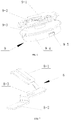
FIG. 2 is an exploded view of the present disclosure, in which a stop button, a pin, a first magnet and a second magnet are in a separate state; -
FIG. 3 is an assembly view of all components of the present disclosure; -
FIG. 4 is an assembly view of all components except a fixing cover of the present disclosure; -
FIG. 5 is a sectional view of the present disclosure; -
FIG. 6 is a perspective view of a rotary wheel of the present disclosure; and -
FIG. 7 is a perspective view of a circuit connection elastic piece of the present disclosure. - In the drawings: 1: rotating shaft; 2: pin; 3: first magnet; 4: stop button; 5: second magnet; 6: fixing cover; 7: FPC connection terminal; 8: circuit connection elastic piece; 8-1: upper connection terminal; 8-2: lower connection terminal; 8-3: fixing hole; 9: rotary wheel; 9-1: ratchet; 9-2: mounting slot; 9-3: cord spool; 9-4: energy storage chamber; 9-5: clamping claw; 10: cord; 11: coil spring; 12: snap ring; 13: seal ring; and 14: rotary wheel cover.
- In order to make the objectives, technical solutions and advantages of the present disclosure clearer, the present disclosure is further described in detail with reference to the accompanying drawings and the embodiments.
-
FIG. 1 ,FIG. 2 ,FIG. 3 andFIG. 4 show an embodiment of the present disclosure. In the present embodiment, a magnetic attraction type cord winding module comprises arotary wheel 9 on which acord 10 is wound and astop button 4 working cooperatively with therotary wheel 9. The cord winding module further comprises a pair of magnet blocks, namely, afirst magnet 3 disposed on thestop button 4 and asecond magnet 5 disposed on therotary wheel 9. Thestop button 4 automatically brakes therotary wheel 9 under the action of the attractive force of the magnet blocks to prevent therotary wheel 9 from retracting thecord 10. - The magnet blocks are strong magnets.
- Alternatively, a repulsive force between the magnet blocks may be utilized. In this case, the first magnet is required to be mounted at the side of the pressing position of the
stop button 4, and accordingly the second magnet must be disposed close to the first magnet. - The
stop button 4 automatically stops the rotating of therotary wheel 9 for retracting thecord 10, but it cannot stop the rotating of therotary wheel 9 for unwinding thecord 10. That is a structural requirement on the cooperation between thestop button 4 and therotary wheel 9. - When the magnet blocks attract, opposite magnetic poles oppose each other, and when the magnet blocks repel, like magnetic poles oppose each other. The interaction surfaces of the magnet blocks are flat.
- As shown in
Fig. 2 and Fig. 3 , the magnet blocks are rectangular blocks. - The cord winding module further comprises a fixing
cover 6. Therotary wheel 9 is installed under the fixingcover 6, and thestop button 4 is installed at a side of the fixingcover 6. One or two receiving grooves for mounting corresponding magnet blocks are provided on the body of the fixingcover 6, and the receiving groove has a notch to expose one end of the magnet block mounted therein. Adhesive may be provided to further fix the magnet blocks. - As shown in
FIG. 2 and FIG. 3 , thestop button 4 is a lever structure, a mounting hole is disposed in the middle of the stop button, the mounting hole is engaged with apin 2 to mount the stop button at a side of the fixingcover 6, and thestop button 4 rotates around thepin 2. One end of thestop button 4 is provided with a U-shaped member for mounting corresponding magnet blocks. Adhesive may be provided to further fix the magnet blocks. - The
stop button 4 may be a metal lever, and the U-shaped member is integrally formed, for example, integrally punched. - By providing the U-shaped member, the first magnet may not protrude from the upper surface of the
stop button 4, and the second magnet can be flattened. This design can effectively reduce the height of the stopper structure and thus reduce the space to be occupied. - As shown in
FIG. 4, FIG. 5 andFIG. 6 , a ratchet 9-1 to cooperate with thestop button 4 is mounted on the upper end of therotary wheel 9, a shaft hole is arranged in the middle of therotary wheel 9, and arotating shaft 1 is fixed on the fixingcover 6. Therotary wheel 9 rotates around therotating shaft 1. Asnap ring 12 is arranged at the lower end of therotating shaft 1, and the rotary wheel is limited on therotating shaft 1 by thesnap ring 12. - When the magnet blocks attract, the
stop button 4 is engaged with the ratchet 9-1 through the U-shaped member. At this point, the U-shaped member acts as a ratchet pawl. - If the cord winding module is provided with a pair of mutually repulsive magnet blocks, a ratchet pawl is required to be provided at the other end of the
stop button 4 to engage with the ratchet 9-1. The ratchet pawl may have a plastic sleeve. When therotary wheel 9 rotates to unwind thecord 10, the plastic sleeve acts as a lubricant between the ratchet pawl and therotary wheel 9. - The detailed structure of the cord winding module is as follows.
- As shown in
FIG. 1 andFIG. 6 , a mounting slot 9-2 is provided at the upper end of therotary wheel 9. A circuit connectionelastic piece 8 is disposed in the mounting slot 9-2. AnFPC connection terminal 7 is provided on the lower surface of the fixingcover 6. One end of the circuit connectionelastic piece 8 is connected to thecord 10, and the other end is connected to theFPC connection terminal 7. The circuit connectionelastic piece 8 is driven by therotary wheel 9 to rotate with respect to theFPC connection terminal 7. - The
FPC connection terminal 7 has a ring shape and is connected with an external flexible printed circuit board (i.e. FPC). The circuit connectionelastic piece 8 is two circuit connectionelastic pieces 8, and they are symmetrically arranged and in contact with theFPC connection terminal 7. Therotary wheel 9 applies a preload to theFPC connection terminal 7 through the circuit connectionelastic pieces 8, so that the reliability of the circuit connection can be fully guaranteed. Both theFPC connection terminal 7 and the circuit connectionelastic pieces 8 are made of a material with good electrical conductivity, such as copper alloy. - A cord is connected between the two circuit connection
elastic pieces 8, and the cord is connected to thecord 10. - As shown in
FIG. 7 , the ends of the circuit connectionelastic pieces 8 which contact theFPC connection terminal 7 have a fork structure (upper connection terminal 8-1 inFIG. 7 ) and has an arc segment. The circuit connectionelastic pieces 8 are connected to theFPC connection terminal 7 through the arc segment, thereby reducing the friction in sliding. - A fixing hole 8-3 is arranged in the middle of the circuit connection
elastic piece 8. Correspondingly, a pin is arranged in the mounting slot 9-2 to cooperate with the fixing hole 8-3. With this design, the circuit connectionelastic piece 8 can more stably rotate with respect to theFPC connection terminal 7. - An energy storage chamber 9-4 is provided at the lower end of the
rotary wheel 9. Acoil spring 11 is installed in the energy storage chamber 9-4. One end of thecoil spring 11 is fixed on therotating shaft 1, and the other end is fixed on the sidewall of the energy storage chamber. When thecord 10 is pulled out, therotary wheel 9 rotates, and thecoil spring 11 is tightened to store energy and provide power for retracting thecord 10 afterwards. - A
rotary wheel cover 14 is installed on the energy storage chamber 9-4. - A clamping hole is provided at a sidewall of the
rotary wheel cover 14. A clamping claw 9-5 is provided on the sidewall of the energy storage chamber 9-4. The energy storage chamber 9-4 is clamped fitted to therotary wheel cover 14. The sidewall of therotary wheel cover 14 is provided with cracks at both sides of the clamping hole, to allow the sidewall to expand outwardly and deform at these positions to fit the clamping claw 9-5. - When the cord winding module is used, due to the attractive force or repulsive force between the magnet blocks, the
stop button 4 is always subject to a pushing force in the opposite direction to the pressing force F, so that one end of thestop button 4 keeps the trend of inserting into the teeth of the ratchet 9-1. - In a normal state, the
rotary wheel 9 can rotate clockwise in the direction of the arrow B, and cannot rotate anticlockwise in the direction of the arrow A due to the braking of thestop button 4. - When the
cord 10 is pulled in the direction of the arrow C inFIG. 4 , therotary wheel 9 rotates clockwise in the direction of the arrow B, and thecoil spring 11 is wound in the opposite direction so that therotary wheel 9 is inclined to rotate anticlockwise in the direction of the arrow A. When thecord 10 is not pulled any longer, due to the action of the stopper structure, one end of thestop button 4 inserts into the teeth of the ratchet 9-1 to prevent therotary wheel 9 from rotating anticlockwise in the direction of the arrow A. When a force F is applied on the end of thestop button 4, the one end of thestop button 4 moves outwardly and disengages from the teeth of the ratchet 9-1, therotary wheel 9 rotates anticlockwise in the direction of the arrow A due to the action of thecoil spring 11, and thecord 10 is retracted into the cord spool 9-3 of the rotary wheel. - As a second embodiment of the present disclosure, a further improvement is made on the basis of the first embodiment. In the second embodiment, a second pair of magnet blocks (not shown), namely, a third magnet disposed on the stop button and a fourth magnet disposed on the rotary wheel, are provided on the stop button. The third magnet and the fourth magnet generate a repulsive force or an attractive force.
- Correspondingly, U-shaped members are provided at the two ends of the stop button to mount corresponding magnet blocks.
- The force applied on the rotary wheel by the stop button can be significantly increased by providing two pairs of magnet blocks, and thus the reliability of the cooperation between them can be ensured.
- As a third embodiment of the present disclosure, a further improvement is made on the basis of the first embodiment. As shown in
FIG. 5 andFIG. 6 , arotary wheel cover 14 is installed on an energy storage chamber 9-4, and aseal ring 13 is provided inside therotary wheel cover 14. A damping grease is provided in the energy storage chamber 9-4. Theseal ring 13 prevents leakage of the damping grease. - The damping grease can adjust the unwinding speed of the
coil spring 11 so that thecord 10 can be slowly retracted to avoid damage to thecord 10. - In a fourth embodiment of the present disclosure, the number of the circuit connection elastic piece is one (not shown), and actually it is obtained by integrally forming two circuit connection
elastic pieces 8 in the first embodiment into one piece. The other structures such as the fork structure are the same except that they are integrally punched and are connected to thecord 10 in the middle of it. This design can simplify the assembling process of the circuit connection portion. - The above description is merely preferable embodiments of the present disclosure. Based on the above teachings of the present disclosure, those skilled in the art may make other improvements or modifications on the basis of the foregoing embodiments. It should be understood by those skilled in the art that the above specific description is only for better explaining the present disclosure, and the protection scope of the present disclosure should be determined by the protection scope of the claims.
Claims (7)
- A magnetic attraction type cord winding module, comprising a fixing cover (6) and a rotary wheel (9), a cord (10) is wound on the rotary wheel (9), and a stop button (4) works cooperatively with the rotary wheel (9), wherein the cord winding module further comprises at least one pair of magnet blocks, the at least one pair of magnet blocks comprise a first magnet (3) disposed on the stop button (4) and a second magnet (5) disposed on the rotary wheel (9), and the stop button (4) automatically brakes the rotary wheel (9) under the action of an attractive force or a repulsive force of the magnet blocks and prevents the rotary wheel (9) from retracting the cord (10);
wherein the rotary wheel (9) is installed under the fixing cover (6), the stop button (4) is installed at a side of the fixing cover (6), one or two receiving grooves for mounting corresponding magnet blocks are provided on the body of the fixing cover (6), and the receiving grooves have a notch, and one end of the magnet blocks mounted in the receiving grooves is exposed from the notch;
wherein the stop button (4) is a lever structure, a mounting hole is disposed in the middle of the stop button (4), the mounting hole is engaged with a pin (2) to mount the stop button (4) at a side of the fixing cover (6), the stop button (4) rotates around the pin (2), and one or both ends of the stop button (4) are provided with a U-shaped member or U-shaped members for mounting corresponding magnet blocks, and
a ratchet (9-1) to cooperate with the stop button (4) is mounted on an upper end of the rotary wheel (9); a shaft hole is arranged in the middle of the rotary wheel (9), and a rotating shaft (1) is fixed on the fixing cover (6); and the rotary wheel (9) rotates around the rotating shaft (1), a snap ring (12) is arranged at a lower end of the rotating shaft (1), and the rotary wheel (9) is limited on the rotating shaft (1) by the snap ring (12). - The cord winding module according to claim 1, wherein the cord winding module further comprises a second pair of magnet blocks, the second pair of magnet blocks comprise a third magnet disposed on the stop button (4) and a fourth magnet disposed on the rotary wheel (9), and the third magnet and the fourth magnet generate a repulsive force or an attractive force.
- The cord winding module according to claim 1, wherein when the magnet blocks attract, opposite magnetic poles oppose each other, and when the magnet blocks repel, like magnetic poles oppose each other; and interaction surfaces of the magnet blocks are flat.
- The cord winding module according to claim 1, wherein the magnet blocks are rectangular blocks or cylinders.
- The cord winding module according to claim 1, wherein the stop button (4) is a metal lever, and the U-shaped member is integrally formed.
- The cord winding module according to claim 1, wherein when the magnet blocks attract, the stop button (4) is engaged with the ratchet (9-1) through the U-shaped member.
- The cord winding module according to claim 1, further comprising a pair of mutually repulsive magnet blocks, one magnet block is mounted on one end of the stop button (4), and a ratchet pawl is provided on the other end of the stop button (4) to engage with the ratchet (9-1).
Applications Claiming Priority (2)
| Application Number | Priority Date | Filing Date | Title |
|---|---|---|---|
| CN201610694227.XA CN106115383B (en) | 2016-08-18 | 2016-08-18 | A kind of magnetic-type spiral module |
| PCT/CN2016/097183 WO2018032533A1 (en) | 2016-08-18 | 2016-08-29 | Magnetic cord reeling module |
Publications (3)
| Publication Number | Publication Date |
|---|---|
| EP3398893A1 EP3398893A1 (en) | 2018-11-07 |
| EP3398893A4 EP3398893A4 (en) | 2018-12-26 |
| EP3398893B1 true EP3398893B1 (en) | 2020-04-22 |
Family
ID=57278335
Family Applications (1)
| Application Number | Title | Priority Date | Filing Date |
|---|---|---|---|
| EP16913289.1A Active EP3398893B1 (en) | 2016-08-18 | 2016-08-29 | Magnetic cord reeling module |
Country Status (5)
| Country | Link |
|---|---|
| US (1) | US10556773B2 (en) |
| EP (1) | EP3398893B1 (en) |
| KR (1) | KR101877157B1 (en) |
| CN (1) | CN106115383B (en) |
| WO (1) | WO2018032533A1 (en) |
Families Citing this family (8)
| Publication number | Priority date | Publication date | Assignee | Title |
|---|---|---|---|---|
| CN106586723A (en) * | 2016-12-28 | 2017-04-26 | 歌尔科技有限公司 | Wire winding module |
| CN111776894A (en) * | 2020-07-03 | 2020-10-16 | 国网山东省电力公司淄博供电公司 | Portable Retractable Transmission Line Ground Wire |
| US12233294B2 (en) * | 2020-09-25 | 2025-02-25 | Werner Co. | Harness adjustment device |
| CN112850382B (en) * | 2021-01-08 | 2022-11-25 | 东莞市森麦声学科技有限公司 | An automatic and fast collection device for earphones |
| KR102707230B1 (en) * | 2022-02-03 | 2024-09-13 | 서울대학교산학협력단 | Variable Clutch |
| CN115258841A (en) * | 2022-04-29 | 2022-11-01 | 哈尔滨工业大学 | Cord release for capturing an object in space with a cord |
| TWI808039B (en) * | 2022-11-17 | 2023-07-01 | 貿聯國際股份有限公司 | Cable winding module and electronic device |
| CN119965628A (en) * | 2025-02-11 | 2025-05-09 | 东莞市杰讯电子科技有限公司 | A telescopic data line module and system |
Family Cites Families (21)
| Publication number | Priority date | Publication date | Assignee | Title |
|---|---|---|---|---|
| US3378214A (en) | 1966-03-11 | 1968-04-16 | Bell Telephone Labor Inc | Latching retractile cord reel |
| US3528624A (en) * | 1968-06-20 | 1970-09-15 | Vacuum Cleaner Corp Of America | Cord-reels |
| US3848827A (en) | 1973-10-03 | 1974-11-19 | B Tamarin | Magnetic rotary locking and release mechanism |
| US4901938A (en) * | 1988-11-21 | 1990-02-20 | Cantley Donald G | Electrical cord retractor |
| JPH02227348A (en) * | 1989-03-01 | 1990-09-10 | Nippon Seiko Kk | Magnet built-in parts for vehicle rider protector |
| TW340532U (en) * | 1995-01-07 | 1998-09-11 | ren-hui Chen | Yarn brake |
| JP2001091806A (en) * | 1999-09-17 | 2001-04-06 | Fujikura Ltd | Optical cable wrapping machine for overhead ground wire |
| CN1232743C (en) | 2001-06-18 | 2005-12-21 | 金锋 | Overrunning clutch |
| CN2444084Y (en) * | 2000-09-29 | 2001-08-22 | 金锋 | Ratchet type overrunning clutch with pawl of magnetically replacing |
| US20050155830A1 (en) | 2004-01-16 | 2005-07-21 | Huang Yea Y. | Multi-functional rolling apparatus |
| CN101234039A (en) * | 2008-03-05 | 2008-08-06 | 程浩玠 | Dental floss holder |
| CN102266212A (en) * | 2010-06-02 | 2011-12-07 | 乐金电子(天津)电器有限公司 | Wire winder |
| EP2452570A1 (en) * | 2010-11-12 | 2012-05-16 | Nestec S.A. | Gel composition |
| CN201914787U (en) * | 2010-12-07 | 2011-08-03 | 乐长琴 | Damping wire take-up device |
| CN103130043B (en) * | 2011-11-25 | 2016-08-10 | 南京乐金熊猫电器有限公司 | Damping Structure for Deceleration of Coil Wheel of Vacuum Cleaner |
| CN103159090B (en) | 2011-12-14 | 2017-04-12 | 富泰华工业(深圳)有限公司 | Containing device |
| KR101292337B1 (en) | 2013-02-08 | 2013-08-01 | 권헌조 | Earphone case for portability |
| CN103457591A (en) * | 2013-08-29 | 2013-12-18 | 青岛歌尔声学科技有限公司 | Rotating reset type adjusting button |
| CN204050774U (en) * | 2014-10-09 | 2014-12-31 | 翟泳雄 | Novel magnetic rope pulling device |
| CN104839110B (en) * | 2015-05-14 | 2017-05-17 | 宁波羚祐渔具有限公司 | Magnetic winder with braking force allowing instant relax |
| CN105680260B (en) * | 2016-03-16 | 2019-08-02 | 青岛歌尔声学科技有限公司 | A kind of spiral mould group |
-
2016
- 2016-08-18 CN CN201610694227.XA patent/CN106115383B/en active Active
- 2016-08-29 KR KR1020167028160A patent/KR101877157B1/en not_active Expired - Fee Related
- 2016-08-29 EP EP16913289.1A patent/EP3398893B1/en active Active
- 2016-08-29 WO PCT/CN2016/097183 patent/WO2018032533A1/en not_active Ceased
- 2016-08-29 US US16/074,624 patent/US10556773B2/en active Active
Non-Patent Citations (1)
| Title |
|---|
| None * |
Also Published As
| Publication number | Publication date |
|---|---|
| US20190337755A1 (en) | 2019-11-07 |
| US10556773B2 (en) | 2020-02-11 |
| WO2018032533A1 (en) | 2018-02-22 |
| KR101877157B1 (en) | 2018-07-10 |
| EP3398893A4 (en) | 2018-12-26 |
| CN106115383B (en) | 2018-09-07 |
| EP3398893A1 (en) | 2018-11-07 |
| CN106115383A (en) | 2016-11-16 |
| KR20180033434A (en) | 2018-04-03 |
Similar Documents
| Publication | Publication Date | Title |
|---|---|---|
| EP3413408B1 (en) | Wire winding module | |
| US10556773B2 (en) | Pull-out type cord winding module | |
| US6416355B1 (en) | Wire-winding box having multiple transmission function | |
| US20160191760A1 (en) | Electronic device having camera | |
| JP6843973B2 (en) | Electrical connector for quick cable locking | |
| CN105580204A (en) | Lead-through terminal and electrical component | |
| US8598479B2 (en) | Electronic device with push button | |
| CN222953485U (en) | Data line device | |
| CN205657280U (en) | Spiral module | |
| KR200497659Y1 (en) | Connector with lock and unlock structure | |
| CN111453551B (en) | Limiting device for preventing limiting disc of winding wheel from deforming | |
| CN101529685B (en) | Universal terminal system for power tools | |
| CN206108582U (en) | Formula spiral module is inhaled to magnetism | |
| CN110729570B (en) | Electrical connection device | |
| US20110155408A1 (en) | Connecting member | |
| CN220138735U (en) | Flexible flat cable connector | |
| KR20210000899U (en) | Thinning connector | |
| CN116683232A (en) | Integrated connector with binding post, cable conductor and cable sheath | |
| CN211350542U (en) | Magnetic tripping system of miniature circuit breaker | |
| US20020051374A1 (en) | Voltage-transforming device having a wire-winding mechanism | |
| TW406452B (en) | Coaxial cable connector | |
| CN110336232B (en) | Explosion-proof terminal box that wiring is efficient | |
| US7931492B1 (en) | Structure of conductive terminal of electrical connector | |
| CN210120162U (en) | Casing and electricity storehouse box | |
| CN214479591U (en) | Surge protector buckle subassembly |
Legal Events
| Date | Code | Title | Description |
|---|---|---|---|
| STAA | Information on the status of an ep patent application or granted ep patent |
Free format text: STATUS: THE INTERNATIONAL PUBLICATION HAS BEEN MADE |
|
| PUAI | Public reference made under article 153(3) epc to a published international application that has entered the european phase |
Free format text: ORIGINAL CODE: 0009012 |
|
| STAA | Information on the status of an ep patent application or granted ep patent |
Free format text: STATUS: REQUEST FOR EXAMINATION WAS MADE |
|
| 17P | Request for examination filed |
Effective date: 20180801 |
|
| AK | Designated contracting states |
Kind code of ref document: A1 Designated state(s): AL AT BE BG CH CY CZ DE DK EE ES FI FR GB GR HR HU IE IS IT LI LT LU LV MC MK MT NL NO PL PT RO RS SE SI SK SM TR |
|
| AX | Request for extension of the european patent |
Extension state: BA ME |
|
| A4 | Supplementary search report drawn up and despatched |
Effective date: 20181128 |
|
| RIC1 | Information provided on ipc code assigned before grant |
Ipc: B65H 75/44 20060101ALI20181123BHEP Ipc: B65H 75/48 20060101AFI20181123BHEP |
|
| STAA | Information on the status of an ep patent application or granted ep patent |
Free format text: STATUS: EXAMINATION IS IN PROGRESS |
|
| 17Q | First examination report despatched |
Effective date: 20190319 |
|
| GRAP | Despatch of communication of intention to grant a patent |
Free format text: ORIGINAL CODE: EPIDOSNIGR1 |
|
| STAA | Information on the status of an ep patent application or granted ep patent |
Free format text: STATUS: GRANT OF PATENT IS INTENDED |
|
| DAV | Request for validation of the european patent (deleted) | ||
| DAX | Request for extension of the european patent (deleted) | ||
| INTG | Intention to grant announced |
Effective date: 20191118 |
|
| GRAS | Grant fee paid |
Free format text: ORIGINAL CODE: EPIDOSNIGR3 |
|
| GRAA | (expected) grant |
Free format text: ORIGINAL CODE: 0009210 |
|
| STAA | Information on the status of an ep patent application or granted ep patent |
Free format text: STATUS: THE PATENT HAS BEEN GRANTED |
|
| AK | Designated contracting states |
Kind code of ref document: B1 Designated state(s): AL AT BE BG CH CY CZ DE DK EE ES FI FR GB GR HR HU IE IS IT LI LT LU LV MC MK MT NL NO PL PT RO RS SE SI SK SM TR |
|
| REG | Reference to a national code |
Ref country code: CH Ref legal event code: EP |
|
| REG | Reference to a national code |
Ref country code: IE Ref legal event code: FG4D |
|
| REG | Reference to a national code |
Ref country code: DE Ref legal event code: R096 Ref document number: 602016034853 Country of ref document: DE |
|
| REG | Reference to a national code |
Ref country code: AT Ref legal event code: REF Ref document number: 1259826 Country of ref document: AT Kind code of ref document: T Effective date: 20200515 |
|
| REG | Reference to a national code |
Ref country code: LT Ref legal event code: MG4D |
|
| REG | Reference to a national code |
Ref country code: NL Ref legal event code: MP Effective date: 20200422 |
|
| PG25 | Lapsed in a contracting state [announced via postgrant information from national office to epo] |
Ref country code: NL Free format text: LAPSE BECAUSE OF FAILURE TO SUBMIT A TRANSLATION OF THE DESCRIPTION OR TO PAY THE FEE WITHIN THE PRESCRIBED TIME-LIMIT Effective date: 20200422 Ref country code: SE Free format text: LAPSE BECAUSE OF FAILURE TO SUBMIT A TRANSLATION OF THE DESCRIPTION OR TO PAY THE FEE WITHIN THE PRESCRIBED TIME-LIMIT Effective date: 20200422 Ref country code: PT Free format text: LAPSE BECAUSE OF FAILURE TO SUBMIT A TRANSLATION OF THE DESCRIPTION OR TO PAY THE FEE WITHIN THE PRESCRIBED TIME-LIMIT Effective date: 20200824 Ref country code: LT Free format text: LAPSE BECAUSE OF FAILURE TO SUBMIT A TRANSLATION OF THE DESCRIPTION OR TO PAY THE FEE WITHIN THE PRESCRIBED TIME-LIMIT Effective date: 20200422 Ref country code: GR Free format text: LAPSE BECAUSE OF FAILURE TO SUBMIT A TRANSLATION OF THE DESCRIPTION OR TO PAY THE FEE WITHIN THE PRESCRIBED TIME-LIMIT Effective date: 20200723 Ref country code: FI Free format text: LAPSE BECAUSE OF FAILURE TO SUBMIT A TRANSLATION OF THE DESCRIPTION OR TO PAY THE FEE WITHIN THE PRESCRIBED TIME-LIMIT Effective date: 20200422 Ref country code: NO Free format text: LAPSE BECAUSE OF FAILURE TO SUBMIT A TRANSLATION OF THE DESCRIPTION OR TO PAY THE FEE WITHIN THE PRESCRIBED TIME-LIMIT Effective date: 20200722 Ref country code: IS Free format text: LAPSE BECAUSE OF FAILURE TO SUBMIT A TRANSLATION OF THE DESCRIPTION OR TO PAY THE FEE WITHIN THE PRESCRIBED TIME-LIMIT Effective date: 20200822 |
|
| REG | Reference to a national code |
Ref country code: AT Ref legal event code: MK05 Ref document number: 1259826 Country of ref document: AT Kind code of ref document: T Effective date: 20200422 |
|
| PG25 | Lapsed in a contracting state [announced via postgrant information from national office to epo] |
Ref country code: LV Free format text: LAPSE BECAUSE OF FAILURE TO SUBMIT A TRANSLATION OF THE DESCRIPTION OR TO PAY THE FEE WITHIN THE PRESCRIBED TIME-LIMIT Effective date: 20200422 Ref country code: HR Free format text: LAPSE BECAUSE OF FAILURE TO SUBMIT A TRANSLATION OF THE DESCRIPTION OR TO PAY THE FEE WITHIN THE PRESCRIBED TIME-LIMIT Effective date: 20200422 Ref country code: BG Free format text: LAPSE BECAUSE OF FAILURE TO SUBMIT A TRANSLATION OF THE DESCRIPTION OR TO PAY THE FEE WITHIN THE PRESCRIBED TIME-LIMIT Effective date: 20200722 Ref country code: RS Free format text: LAPSE BECAUSE OF FAILURE TO SUBMIT A TRANSLATION OF THE DESCRIPTION OR TO PAY THE FEE WITHIN THE PRESCRIBED TIME-LIMIT Effective date: 20200422 |
|
| PG25 | Lapsed in a contracting state [announced via postgrant information from national office to epo] |
Ref country code: AL Free format text: LAPSE BECAUSE OF FAILURE TO SUBMIT A TRANSLATION OF THE DESCRIPTION OR TO PAY THE FEE WITHIN THE PRESCRIBED TIME-LIMIT Effective date: 20200422 |
|
| REG | Reference to a national code |
Ref country code: DE Ref legal event code: R097 Ref document number: 602016034853 Country of ref document: DE |
|
| PG25 | Lapsed in a contracting state [announced via postgrant information from national office to epo] |
Ref country code: IT Free format text: LAPSE BECAUSE OF FAILURE TO SUBMIT A TRANSLATION OF THE DESCRIPTION OR TO PAY THE FEE WITHIN THE PRESCRIBED TIME-LIMIT Effective date: 20200422 Ref country code: RO Free format text: LAPSE BECAUSE OF FAILURE TO SUBMIT A TRANSLATION OF THE DESCRIPTION OR TO PAY THE FEE WITHIN THE PRESCRIBED TIME-LIMIT Effective date: 20200422 Ref country code: CZ Free format text: LAPSE BECAUSE OF FAILURE TO SUBMIT A TRANSLATION OF THE DESCRIPTION OR TO PAY THE FEE WITHIN THE PRESCRIBED TIME-LIMIT Effective date: 20200422 Ref country code: DK Free format text: LAPSE BECAUSE OF FAILURE TO SUBMIT A TRANSLATION OF THE DESCRIPTION OR TO PAY THE FEE WITHIN THE PRESCRIBED TIME-LIMIT Effective date: 20200422 Ref country code: ES Free format text: LAPSE BECAUSE OF FAILURE TO SUBMIT A TRANSLATION OF THE DESCRIPTION OR TO PAY THE FEE WITHIN THE PRESCRIBED TIME-LIMIT Effective date: 20200422 Ref country code: AT Free format text: LAPSE BECAUSE OF FAILURE TO SUBMIT A TRANSLATION OF THE DESCRIPTION OR TO PAY THE FEE WITHIN THE PRESCRIBED TIME-LIMIT Effective date: 20200422 Ref country code: EE Free format text: LAPSE BECAUSE OF FAILURE TO SUBMIT A TRANSLATION OF THE DESCRIPTION OR TO PAY THE FEE WITHIN THE PRESCRIBED TIME-LIMIT Effective date: 20200422 Ref country code: SM Free format text: LAPSE BECAUSE OF FAILURE TO SUBMIT A TRANSLATION OF THE DESCRIPTION OR TO PAY THE FEE WITHIN THE PRESCRIBED TIME-LIMIT Effective date: 20200422 |
|
| PG25 | Lapsed in a contracting state [announced via postgrant information from national office to epo] |
Ref country code: SK Free format text: LAPSE BECAUSE OF FAILURE TO SUBMIT A TRANSLATION OF THE DESCRIPTION OR TO PAY THE FEE WITHIN THE PRESCRIBED TIME-LIMIT Effective date: 20200422 Ref country code: PL Free format text: LAPSE BECAUSE OF FAILURE TO SUBMIT A TRANSLATION OF THE DESCRIPTION OR TO PAY THE FEE WITHIN THE PRESCRIBED TIME-LIMIT Effective date: 20200422 |
|
| PLBE | No opposition filed within time limit |
Free format text: ORIGINAL CODE: 0009261 |
|
| STAA | Information on the status of an ep patent application or granted ep patent |
Free format text: STATUS: NO OPPOSITION FILED WITHIN TIME LIMIT |
|
| 26N | No opposition filed |
Effective date: 20210125 |
|
| PG25 | Lapsed in a contracting state [announced via postgrant information from national office to epo] |
Ref country code: MC Free format text: LAPSE BECAUSE OF FAILURE TO SUBMIT A TRANSLATION OF THE DESCRIPTION OR TO PAY THE FEE WITHIN THE PRESCRIBED TIME-LIMIT Effective date: 20200422 |
|
| REG | Reference to a national code |
Ref country code: CH Ref legal event code: PL |
|
| PG25 | Lapsed in a contracting state [announced via postgrant information from national office to epo] |
Ref country code: LU Free format text: LAPSE BECAUSE OF NON-PAYMENT OF DUE FEES Effective date: 20200829 Ref country code: LI Free format text: LAPSE BECAUSE OF NON-PAYMENT OF DUE FEES Effective date: 20200831 Ref country code: CH Free format text: LAPSE BECAUSE OF NON-PAYMENT OF DUE FEES Effective date: 20200831 |
|
| REG | Reference to a national code |
Ref country code: BE Ref legal event code: MM Effective date: 20200831 |
|
| PG25 | Lapsed in a contracting state [announced via postgrant information from national office to epo] |
Ref country code: SI Free format text: LAPSE BECAUSE OF FAILURE TO SUBMIT A TRANSLATION OF THE DESCRIPTION OR TO PAY THE FEE WITHIN THE PRESCRIBED TIME-LIMIT Effective date: 20200422 |
|
| PG25 | Lapsed in a contracting state [announced via postgrant information from national office to epo] |
Ref country code: IE Free format text: LAPSE BECAUSE OF NON-PAYMENT OF DUE FEES Effective date: 20200829 Ref country code: BE Free format text: LAPSE BECAUSE OF NON-PAYMENT OF DUE FEES Effective date: 20200831 |
|
| PG25 | Lapsed in a contracting state [announced via postgrant information from national office to epo] |
Ref country code: TR Free format text: LAPSE BECAUSE OF FAILURE TO SUBMIT A TRANSLATION OF THE DESCRIPTION OR TO PAY THE FEE WITHIN THE PRESCRIBED TIME-LIMIT Effective date: 20200422 Ref country code: MT Free format text: LAPSE BECAUSE OF FAILURE TO SUBMIT A TRANSLATION OF THE DESCRIPTION OR TO PAY THE FEE WITHIN THE PRESCRIBED TIME-LIMIT Effective date: 20200422 Ref country code: CY Free format text: LAPSE BECAUSE OF FAILURE TO SUBMIT A TRANSLATION OF THE DESCRIPTION OR TO PAY THE FEE WITHIN THE PRESCRIBED TIME-LIMIT Effective date: 20200422 |
|
| PG25 | Lapsed in a contracting state [announced via postgrant information from national office to epo] |
Ref country code: MK Free format text: LAPSE BECAUSE OF FAILURE TO SUBMIT A TRANSLATION OF THE DESCRIPTION OR TO PAY THE FEE WITHIN THE PRESCRIBED TIME-LIMIT Effective date: 20200422 |
|
| PGFP | Annual fee paid to national office [announced via postgrant information from national office to epo] |
Ref country code: GB Payment date: 20230824 Year of fee payment: 8 |
|
| PGFP | Annual fee paid to national office [announced via postgrant information from national office to epo] |
Ref country code: FR Payment date: 20230828 Year of fee payment: 8 Ref country code: DE Payment date: 20230808 Year of fee payment: 8 |
|
| REG | Reference to a national code |
Ref country code: DE Ref legal event code: R119 Ref document number: 602016034853 Country of ref document: DE |
|
| GBPC | Gb: european patent ceased through non-payment of renewal fee |
Effective date: 20240829 |
|
| PG25 | Lapsed in a contracting state [announced via postgrant information from national office to epo] |
Ref country code: DE Free format text: LAPSE BECAUSE OF NON-PAYMENT OF DUE FEES Effective date: 20250301 |
|
| PG25 | Lapsed in a contracting state [announced via postgrant information from national office to epo] |
Ref country code: GB Free format text: LAPSE BECAUSE OF NON-PAYMENT OF DUE FEES Effective date: 20240829 |
|
| PG25 | Lapsed in a contracting state [announced via postgrant information from national office to epo] |
Ref country code: FR Free format text: LAPSE BECAUSE OF NON-PAYMENT OF DUE FEES Effective date: 20240831 |