EP3398858A1 - Spacecraft fuel tank and manufacturing method therefor - Google Patents
Spacecraft fuel tank and manufacturing method therefor Download PDFInfo
- Publication number
- EP3398858A1 EP3398858A1 EP16881768.2A EP16881768A EP3398858A1 EP 3398858 A1 EP3398858 A1 EP 3398858A1 EP 16881768 A EP16881768 A EP 16881768A EP 3398858 A1 EP3398858 A1 EP 3398858A1
- Authority
- EP
- European Patent Office
- Prior art keywords
- fuel tank
- spacecraft
- carbon fiber
- fiber reinforced
- reinforced plastic
- Prior art date
- Legal status (The legal status is an assumption and is not a legal conclusion. Google has not performed a legal analysis and makes no representation as to the accuracy of the status listed.)
- Granted
Links
- 239000002828 fuel tank Substances 0.000 title claims abstract description 461
- 238000004519 manufacturing process Methods 0.000 title claims description 118
- 238000007747 plating Methods 0.000 claims abstract description 265
- 239000004918 carbon fiber reinforced polymer Substances 0.000 claims abstract description 156
- 238000012545 processing Methods 0.000 claims abstract description 110
- 238000005498 polishing Methods 0.000 claims abstract description 100
- 239000000446 fuel Substances 0.000 claims abstract description 21
- PXHVJJICTQNCMI-UHFFFAOYSA-N Nickel Chemical compound [Ni] PXHVJJICTQNCMI-UHFFFAOYSA-N 0.000 claims description 48
- 238000000034 method Methods 0.000 claims description 32
- RYGMFSIKBFXOCR-UHFFFAOYSA-N Copper Chemical compound [Cu] RYGMFSIKBFXOCR-UHFFFAOYSA-N 0.000 claims description 24
- 229910052802 copper Inorganic materials 0.000 claims description 24
- 239000010949 copper Substances 0.000 claims description 24
- 229910052759 nickel Inorganic materials 0.000 claims description 24
- MYMOFIZGZYHOMD-UHFFFAOYSA-N Dioxygen Chemical compound O=O MYMOFIZGZYHOMD-UHFFFAOYSA-N 0.000 description 31
- 238000009713 electroplating Methods 0.000 description 27
- 239000000470 constituent Substances 0.000 description 19
- 230000003746 surface roughness Effects 0.000 description 18
- 229920005989 resin Polymers 0.000 description 8
- 239000011347 resin Substances 0.000 description 8
- 239000002131 composite material Substances 0.000 description 5
- 229910052751 metal Inorganic materials 0.000 description 5
- 239000002184 metal Substances 0.000 description 5
- 239000003795 chemical substances by application Substances 0.000 description 4
- 239000004744 fabric Substances 0.000 description 4
- 238000006243 chemical reaction Methods 0.000 description 3
- 239000002737 fuel gas Substances 0.000 description 3
- 239000007788 liquid Substances 0.000 description 3
- BASFCYQUMIYNBI-UHFFFAOYSA-N platinum Chemical compound [Pt] BASFCYQUMIYNBI-UHFFFAOYSA-N 0.000 description 2
- 238000007790 scraping Methods 0.000 description 2
- 239000000126 substance Substances 0.000 description 2
- 238000012360 testing method Methods 0.000 description 2
- XQUPVDVFXZDTLT-UHFFFAOYSA-N 1-[4-[[4-(2,5-dioxopyrrol-1-yl)phenyl]methyl]phenyl]pyrrole-2,5-dione Chemical compound O=C1C=CC(=O)N1C(C=C1)=CC=C1CC1=CC=C(N2C(C=CC2=O)=O)C=C1 XQUPVDVFXZDTLT-UHFFFAOYSA-N 0.000 description 1
- 229920000049 Carbon (fiber) Polymers 0.000 description 1
- VYZAMTAEIAYCRO-UHFFFAOYSA-N Chromium Chemical compound [Cr] VYZAMTAEIAYCRO-UHFFFAOYSA-N 0.000 description 1
- UFHFLCQGNIYNRP-UHFFFAOYSA-N Hydrogen Chemical compound [H][H] UFHFLCQGNIYNRP-UHFFFAOYSA-N 0.000 description 1
- 239000004696 Poly ether ether ketone Substances 0.000 description 1
- BQCADISMDOOEFD-UHFFFAOYSA-N Silver Chemical compound [Ag] BQCADISMDOOEFD-UHFFFAOYSA-N 0.000 description 1
- ATJFFYVFTNAWJD-UHFFFAOYSA-N Tin Chemical compound [Sn] ATJFFYVFTNAWJD-UHFFFAOYSA-N 0.000 description 1
- HCHKCACWOHOZIP-UHFFFAOYSA-N Zinc Chemical compound [Zn] HCHKCACWOHOZIP-UHFFFAOYSA-N 0.000 description 1
- 239000000853 adhesive Substances 0.000 description 1
- 230000001070 adhesive effect Effects 0.000 description 1
- 229910045601 alloy Inorganic materials 0.000 description 1
- 239000000956 alloy Substances 0.000 description 1
- 229910052782 aluminium Inorganic materials 0.000 description 1
- XAGFODPZIPBFFR-UHFFFAOYSA-N aluminium Chemical compound [Al] XAGFODPZIPBFFR-UHFFFAOYSA-N 0.000 description 1
- 229910052793 cadmium Inorganic materials 0.000 description 1
- BDOSMKKIYDKNTQ-UHFFFAOYSA-N cadmium atom Chemical compound [Cd] BDOSMKKIYDKNTQ-UHFFFAOYSA-N 0.000 description 1
- 239000004917 carbon fiber Substances 0.000 description 1
- 230000000694 effects Effects 0.000 description 1
- 239000003822 epoxy resin Substances 0.000 description 1
- 238000002474 experimental method Methods 0.000 description 1
- PCHJSUWPFVWCPO-UHFFFAOYSA-N gold Chemical compound [Au] PCHJSUWPFVWCPO-UHFFFAOYSA-N 0.000 description 1
- 229910052737 gold Inorganic materials 0.000 description 1
- 239000010931 gold Substances 0.000 description 1
- 239000001307 helium Substances 0.000 description 1
- 229910052734 helium Inorganic materials 0.000 description 1
- SWQJXJOGLNCZEY-UHFFFAOYSA-N helium atom Chemical compound [He] SWQJXJOGLNCZEY-UHFFFAOYSA-N 0.000 description 1
- 239000001257 hydrogen Substances 0.000 description 1
- 229910052739 hydrogen Inorganic materials 0.000 description 1
- 238000009863 impact test Methods 0.000 description 1
- 239000000463 material Substances 0.000 description 1
- 150000002739 metals Chemical class 0.000 description 1
- 238000012986 modification Methods 0.000 description 1
- 230000004048 modification Effects 0.000 description 1
- UCAHJECAHMOSHI-UHFFFAOYSA-N n-[(5-bromo-2-methoxyphenyl)methyl]adamantan-1-amine Chemical compound COC1=CC=C(Br)C=C1CNC1(C2)CC(C3)CC2CC3C1 UCAHJECAHMOSHI-UHFFFAOYSA-N 0.000 description 1
- 239000005011 phenolic resin Substances 0.000 description 1
- 229910052697 platinum Inorganic materials 0.000 description 1
- 229920003192 poly(bis maleimide) Polymers 0.000 description 1
- 229920001652 poly(etherketoneketone) Polymers 0.000 description 1
- 229920000647 polyepoxide Polymers 0.000 description 1
- 229920002530 polyetherether ketone Polymers 0.000 description 1
- 238000004439 roughness measurement Methods 0.000 description 1
- 229910052709 silver Inorganic materials 0.000 description 1
- 239000004332 silver Substances 0.000 description 1
- 238000010998 test method Methods 0.000 description 1
- 229910052718 tin Inorganic materials 0.000 description 1
- 229910052725 zinc Inorganic materials 0.000 description 1
- 239000011701 zinc Substances 0.000 description 1
Images


Classifications
-
- C—CHEMISTRY; METALLURGY
- C25—ELECTROLYTIC OR ELECTROPHORETIC PROCESSES; APPARATUS THEREFOR
- C25D—PROCESSES FOR THE ELECTROLYTIC OR ELECTROPHORETIC PRODUCTION OF COATINGS; ELECTROFORMING; APPARATUS THEREFOR
- C25D5/00—Electroplating characterised by the process; Pretreatment or after-treatment of workpieces
-
- B—PERFORMING OPERATIONS; TRANSPORTING
- B29—WORKING OF PLASTICS; WORKING OF SUBSTANCES IN A PLASTIC STATE IN GENERAL
- B29C—SHAPING OR JOINING OF PLASTICS; SHAPING OF MATERIAL IN A PLASTIC STATE, NOT OTHERWISE PROVIDED FOR; AFTER-TREATMENT OF THE SHAPED PRODUCTS, e.g. REPAIRING
- B29C70/00—Shaping composites, i.e. plastics material comprising reinforcements, fillers or preformed parts, e.g. inserts
- B29C70/04—Shaping composites, i.e. plastics material comprising reinforcements, fillers or preformed parts, e.g. inserts comprising reinforcements only, e.g. self-reinforcing plastics
- B29C70/06—Fibrous reinforcements only
- B29C70/10—Fibrous reinforcements only characterised by the structure of fibrous reinforcements, e.g. hollow fibres
- B29C70/16—Fibrous reinforcements only characterised by the structure of fibrous reinforcements, e.g. hollow fibres using fibres of substantial or continuous length
-
- B—PERFORMING OPERATIONS; TRANSPORTING
- B64—AIRCRAFT; AVIATION; COSMONAUTICS
- B64G—COSMONAUTICS; VEHICLES OR EQUIPMENT THEREFOR
- B64G1/00—Cosmonautic vehicles
- B64G1/22—Parts of, or equipment specially adapted for fitting in or to, cosmonautic vehicles
- B64G1/40—Arrangements or adaptations of propulsion systems
- B64G1/402—Propellant tanks; Feeding propellants
-
- C—CHEMISTRY; METALLURGY
- C23—COATING METALLIC MATERIAL; COATING MATERIAL WITH METALLIC MATERIAL; CHEMICAL SURFACE TREATMENT; DIFFUSION TREATMENT OF METALLIC MATERIAL; COATING BY VACUUM EVAPORATION, BY SPUTTERING, BY ION IMPLANTATION OR BY CHEMICAL VAPOUR DEPOSITION, IN GENERAL; INHIBITING CORROSION OF METALLIC MATERIAL OR INCRUSTATION IN GENERAL
- C23C—COATING METALLIC MATERIAL; COATING MATERIAL WITH METALLIC MATERIAL; SURFACE TREATMENT OF METALLIC MATERIAL BY DIFFUSION INTO THE SURFACE, BY CHEMICAL CONVERSION OR SUBSTITUTION; COATING BY VACUUM EVAPORATION, BY SPUTTERING, BY ION IMPLANTATION OR BY CHEMICAL VAPOUR DEPOSITION, IN GENERAL
- C23C18/00—Chemical coating by decomposition of either liquid compounds or solutions of the coating forming compounds, without leaving reaction products of surface material in the coating; Contact plating
- C23C18/02—Chemical coating by decomposition of either liquid compounds or solutions of the coating forming compounds, without leaving reaction products of surface material in the coating; Contact plating by thermal decomposition
- C23C18/12—Chemical coating by decomposition of either liquid compounds or solutions of the coating forming compounds, without leaving reaction products of surface material in the coating; Contact plating by thermal decomposition characterised by the deposition of inorganic material other than metallic material
- C23C18/1229—Composition of the substrate
- C23C18/1245—Inorganic substrates other than metallic
-
- C—CHEMISTRY; METALLURGY
- C23—COATING METALLIC MATERIAL; COATING MATERIAL WITH METALLIC MATERIAL; CHEMICAL SURFACE TREATMENT; DIFFUSION TREATMENT OF METALLIC MATERIAL; COATING BY VACUUM EVAPORATION, BY SPUTTERING, BY ION IMPLANTATION OR BY CHEMICAL VAPOUR DEPOSITION, IN GENERAL; INHIBITING CORROSION OF METALLIC MATERIAL OR INCRUSTATION IN GENERAL
- C23C—COATING METALLIC MATERIAL; COATING MATERIAL WITH METALLIC MATERIAL; SURFACE TREATMENT OF METALLIC MATERIAL BY DIFFUSION INTO THE SURFACE, BY CHEMICAL CONVERSION OR SUBSTITUTION; COATING BY VACUUM EVAPORATION, BY SPUTTERING, BY ION IMPLANTATION OR BY CHEMICAL VAPOUR DEPOSITION, IN GENERAL
- C23C18/00—Chemical coating by decomposition of either liquid compounds or solutions of the coating forming compounds, without leaving reaction products of surface material in the coating; Contact plating
- C23C18/16—Chemical coating by decomposition of either liquid compounds or solutions of the coating forming compounds, without leaving reaction products of surface material in the coating; Contact plating by reduction or substitution, e.g. electroless plating
- C23C18/1601—Process or apparatus
- C23C18/1633—Process of electroless plating
- C23C18/1646—Characteristics of the product obtained
- C23C18/165—Multilayered product
- C23C18/1653—Two or more layers with at least one layer obtained by electroless plating and one layer obtained by electroplating
-
- C—CHEMISTRY; METALLURGY
- C23—COATING METALLIC MATERIAL; COATING MATERIAL WITH METALLIC MATERIAL; CHEMICAL SURFACE TREATMENT; DIFFUSION TREATMENT OF METALLIC MATERIAL; COATING BY VACUUM EVAPORATION, BY SPUTTERING, BY ION IMPLANTATION OR BY CHEMICAL VAPOUR DEPOSITION, IN GENERAL; INHIBITING CORROSION OF METALLIC MATERIAL OR INCRUSTATION IN GENERAL
- C23C—COATING METALLIC MATERIAL; COATING MATERIAL WITH METALLIC MATERIAL; SURFACE TREATMENT OF METALLIC MATERIAL BY DIFFUSION INTO THE SURFACE, BY CHEMICAL CONVERSION OR SUBSTITUTION; COATING BY VACUUM EVAPORATION, BY SPUTTERING, BY ION IMPLANTATION OR BY CHEMICAL VAPOUR DEPOSITION, IN GENERAL
- C23C18/00—Chemical coating by decomposition of either liquid compounds or solutions of the coating forming compounds, without leaving reaction products of surface material in the coating; Contact plating
- C23C18/16—Chemical coating by decomposition of either liquid compounds or solutions of the coating forming compounds, without leaving reaction products of surface material in the coating; Contact plating by reduction or substitution, e.g. electroless plating
- C23C18/1601—Process or apparatus
- C23C18/1633—Process of electroless plating
- C23C18/1689—After-treatment
-
- C—CHEMISTRY; METALLURGY
- C23—COATING METALLIC MATERIAL; COATING MATERIAL WITH METALLIC MATERIAL; CHEMICAL SURFACE TREATMENT; DIFFUSION TREATMENT OF METALLIC MATERIAL; COATING BY VACUUM EVAPORATION, BY SPUTTERING, BY ION IMPLANTATION OR BY CHEMICAL VAPOUR DEPOSITION, IN GENERAL; INHIBITING CORROSION OF METALLIC MATERIAL OR INCRUSTATION IN GENERAL
- C23C—COATING METALLIC MATERIAL; COATING MATERIAL WITH METALLIC MATERIAL; SURFACE TREATMENT OF METALLIC MATERIAL BY DIFFUSION INTO THE SURFACE, BY CHEMICAL CONVERSION OR SUBSTITUTION; COATING BY VACUUM EVAPORATION, BY SPUTTERING, BY ION IMPLANTATION OR BY CHEMICAL VAPOUR DEPOSITION, IN GENERAL
- C23C18/00—Chemical coating by decomposition of either liquid compounds or solutions of the coating forming compounds, without leaving reaction products of surface material in the coating; Contact plating
- C23C18/16—Chemical coating by decomposition of either liquid compounds or solutions of the coating forming compounds, without leaving reaction products of surface material in the coating; Contact plating by reduction or substitution, e.g. electroless plating
- C23C18/18—Pretreatment of the material to be coated
- C23C18/1851—Pretreatment of the material to be coated of surfaces of non-metallic or semiconducting in organic material
- C23C18/1855—Pretreatment of the material to be coated of surfaces of non-metallic or semiconducting in organic material by mechanical pretreatment, e.g. grinding, sanding
-
- C—CHEMISTRY; METALLURGY
- C23—COATING METALLIC MATERIAL; COATING MATERIAL WITH METALLIC MATERIAL; CHEMICAL SURFACE TREATMENT; DIFFUSION TREATMENT OF METALLIC MATERIAL; COATING BY VACUUM EVAPORATION, BY SPUTTERING, BY ION IMPLANTATION OR BY CHEMICAL VAPOUR DEPOSITION, IN GENERAL; INHIBITING CORROSION OF METALLIC MATERIAL OR INCRUSTATION IN GENERAL
- C23C—COATING METALLIC MATERIAL; COATING MATERIAL WITH METALLIC MATERIAL; SURFACE TREATMENT OF METALLIC MATERIAL BY DIFFUSION INTO THE SURFACE, BY CHEMICAL CONVERSION OR SUBSTITUTION; COATING BY VACUUM EVAPORATION, BY SPUTTERING, BY ION IMPLANTATION OR BY CHEMICAL VAPOUR DEPOSITION, IN GENERAL
- C23C18/00—Chemical coating by decomposition of either liquid compounds or solutions of the coating forming compounds, without leaving reaction products of surface material in the coating; Contact plating
- C23C18/16—Chemical coating by decomposition of either liquid compounds or solutions of the coating forming compounds, without leaving reaction products of surface material in the coating; Contact plating by reduction or substitution, e.g. electroless plating
- C23C18/18—Pretreatment of the material to be coated
- C23C18/20—Pretreatment of the material to be coated of organic surfaces, e.g. resins
- C23C18/2006—Pretreatment of the material to be coated of organic surfaces, e.g. resins by other methods than those of C23C18/22 - C23C18/30
- C23C18/2013—Pretreatment of the material to be coated of organic surfaces, e.g. resins by other methods than those of C23C18/22 - C23C18/30 by mechanical pretreatment, e.g. grinding, sanding
-
- C—CHEMISTRY; METALLURGY
- C23—COATING METALLIC MATERIAL; COATING MATERIAL WITH METALLIC MATERIAL; CHEMICAL SURFACE TREATMENT; DIFFUSION TREATMENT OF METALLIC MATERIAL; COATING BY VACUUM EVAPORATION, BY SPUTTERING, BY ION IMPLANTATION OR BY CHEMICAL VAPOUR DEPOSITION, IN GENERAL; INHIBITING CORROSION OF METALLIC MATERIAL OR INCRUSTATION IN GENERAL
- C23C—COATING METALLIC MATERIAL; COATING MATERIAL WITH METALLIC MATERIAL; SURFACE TREATMENT OF METALLIC MATERIAL BY DIFFUSION INTO THE SURFACE, BY CHEMICAL CONVERSION OR SUBSTITUTION; COATING BY VACUUM EVAPORATION, BY SPUTTERING, BY ION IMPLANTATION OR BY CHEMICAL VAPOUR DEPOSITION, IN GENERAL
- C23C18/00—Chemical coating by decomposition of either liquid compounds or solutions of the coating forming compounds, without leaving reaction products of surface material in the coating; Contact plating
- C23C18/16—Chemical coating by decomposition of either liquid compounds or solutions of the coating forming compounds, without leaving reaction products of surface material in the coating; Contact plating by reduction or substitution, e.g. electroless plating
- C23C18/31—Coating with metals
- C23C18/32—Coating with nickel, cobalt or mixtures thereof with phosphorus or boron
-
- C—CHEMISTRY; METALLURGY
- C25—ELECTROLYTIC OR ELECTROPHORETIC PROCESSES; APPARATUS THEREFOR
- C25D—PROCESSES FOR THE ELECTROLYTIC OR ELECTROPHORETIC PRODUCTION OF COATINGS; ELECTROFORMING; APPARATUS THEREFOR
- C25D5/00—Electroplating characterised by the process; Pretreatment or after-treatment of workpieces
- C25D5/48—After-treatment of electroplated surfaces
- C25D5/52—After-treatment of electroplated surfaces by brightening or burnishing
-
- C—CHEMISTRY; METALLURGY
- C25—ELECTROLYTIC OR ELECTROPHORETIC PROCESSES; APPARATUS THEREFOR
- C25D—PROCESSES FOR THE ELECTROLYTIC OR ELECTROPHORETIC PRODUCTION OF COATINGS; ELECTROFORMING; APPARATUS THEREFOR
- C25D5/00—Electroplating characterised by the process; Pretreatment or after-treatment of workpieces
- C25D5/54—Electroplating of non-metallic surfaces
- C25D5/56—Electroplating of non-metallic surfaces of plastics
-
- C—CHEMISTRY; METALLURGY
- C25—ELECTROLYTIC OR ELECTROPHORETIC PROCESSES; APPARATUS THEREFOR
- C25D—PROCESSES FOR THE ELECTROLYTIC OR ELECTROPHORETIC PRODUCTION OF COATINGS; ELECTROFORMING; APPARATUS THEREFOR
- C25D7/00—Electroplating characterised by the article coated
- C25D7/04—Tubes; Rings; Hollow bodies
-
- B—PERFORMING OPERATIONS; TRANSPORTING
- B32—LAYERED PRODUCTS
- B32B—LAYERED PRODUCTS, i.e. PRODUCTS BUILT-UP OF STRATA OF FLAT OR NON-FLAT, e.g. CELLULAR OR HONEYCOMB, FORM
- B32B15/00—Layered products comprising a layer of metal
- B32B15/04—Layered products comprising a layer of metal comprising metal as the main or only constituent of a layer, which is next to another layer of the same or of a different material
-
- B—PERFORMING OPERATIONS; TRANSPORTING
- B32—LAYERED PRODUCTS
- B32B—LAYERED PRODUCTS, i.e. PRODUCTS BUILT-UP OF STRATA OF FLAT OR NON-FLAT, e.g. CELLULAR OR HONEYCOMB, FORM
- B32B2605/00—Vehicles
-
- B—PERFORMING OPERATIONS; TRANSPORTING
- B32—LAYERED PRODUCTS
- B32B—LAYERED PRODUCTS, i.e. PRODUCTS BUILT-UP OF STRATA OF FLAT OR NON-FLAT, e.g. CELLULAR OR HONEYCOMB, FORM
- B32B5/00—Layered products characterised by the non- homogeneity or physical structure, i.e. comprising a fibrous, filamentary, particulate or foam layer; Layered products characterised by having a layer differing constitutionally or physically in different parts
- B32B5/02—Layered products characterised by the non- homogeneity or physical structure, i.e. comprising a fibrous, filamentary, particulate or foam layer; Layered products characterised by having a layer differing constitutionally or physically in different parts characterised by structural features of a fibrous or filamentary layer
- B32B5/08—Layered products characterised by the non- homogeneity or physical structure, i.e. comprising a fibrous, filamentary, particulate or foam layer; Layered products characterised by having a layer differing constitutionally or physically in different parts characterised by structural features of a fibrous or filamentary layer the fibres or filaments of a layer being of different substances, e.g. conjugate fibres, mixture of different fibres
-
- B—PERFORMING OPERATIONS; TRANSPORTING
- B32—LAYERED PRODUCTS
- B32B—LAYERED PRODUCTS, i.e. PRODUCTS BUILT-UP OF STRATA OF FLAT OR NON-FLAT, e.g. CELLULAR OR HONEYCOMB, FORM
- B32B9/00—Layered products comprising a layer of a particular substance not covered by groups B32B11/00 - B32B29/00
- B32B9/005—Layered products comprising a layer of a particular substance not covered by groups B32B11/00 - B32B29/00 comprising one layer of ceramic material, e.g. porcelain, ceramic tile
- B32B9/007—Layered products comprising a layer of a particular substance not covered by groups B32B11/00 - B32B29/00 comprising one layer of ceramic material, e.g. porcelain, ceramic tile comprising carbon, e.g. graphite, composite carbon
Definitions
- the present invention relates to a fuel tank for use with a spacecraft (fuel tank for spacecraft), and a manufacturing method thereof.
- Patent Literature 1 To reduce the weight of a pressure container (pressure vessel) mounted in an aerospace vehicle (payload) in which an artificial satellite or the like is mounted, a manufacturing method of a composite pressure container (vessel) is known, in which the thickness of a metal layer is reduced (e.g., see Patent Literature 1). In the manufacturing method of the composite pressure container disclosed in Patent Literature 1, the weight of the pressure container for storing helium therein is reduced.
- Patent Literature 1 Japanese Laid-Open Patent Application Publication No. 2002-139197
- An object of the present invention is to provide a fuel tank for use with a spacecraft, and a manufacturing method thereof, which can solve at least one of the above-described two problems.
- a fuel tank for use with a spacecraft, the fuel tank being configured to store therein fuel for driving the spacecraft, the fuel tank comprising: a carbon fiber reinforced plastic layer and a metallic plating layer, wherein the carbon fiber reinforced plastic layer has a polished surface having been subjected to polishing processing, the polished surface being on an inner side of the fuel tank, and wherein the metallic plating layer is provided on the polished surface.
- the inner surface of the fuel tank for use with the spacecraft is smoothed. Even in a case where liquid oxygen is stored in the fuel tank for use with the spacecraft, resistance to ignition in a liquid oxygen ambience can be improved.
- a fuel tank for use with a spacecraft, the fuel tank being configured to store therein fuel for driving the spacecraft, the fuel tank comprising: a carbon fiber reinforced plastic layer and a metallic plating layer, wherein the carbon fiber reinforced plastic layer has a polished surface having been subjected to polishing processing, the polished surface being on an inner side of the fuel tank, and wherein the metallic plating layer is provided on an outer side of the fuel tank.
- the inner surface of the fuel tank for use with the spacecraft is smoothed. Even in a case where liquid oxygen is stored in the fuel tank for use with the spacecraft, resistance to ignition in a liquid oxygen ambience can be improved.
- a fuel tank for use with a spacecraft, the fuel tank being configured to store therein fuel for driving the spacecraft, the fuel tank comprising: a carbon fiber reinforced plastic layer and metallic plating layers, wherein the carbon fiber reinforced plastic layer has a polished surface having been subjected to polishing processing, the polished surface being on an inner side of the fuel tank, and wherein the metallic plating layers are provided on the polished surface and on a surface of the carbon fiber reinforced plastic layer, the surface being an outer side of the fuel tank.
- the inner surface of the fuel tank for use with the spacecraft is smoothed. Even in a case where liquid oxygen is stored in the fuel tank for use with the spacecraft, resistance to ignition in a liquid oxygen ambience can be improved.
- a fuel tank for use with a spacecraft, the fuel tank being configured to store therein fuel for driving the spacecraft, the fuel tank comprising: a carbon fiber reinforced plastic layer; and a metallic plating layer covering a surface of the carbon fiber reinforced plastic layer, the surface being on an inner side of the fuel tank, wherein the metallic plating layer has a polished surface having been subjected to polishing processing, the polished surface being on the inner side of the fuel tank.
- the inner surface of the fuel tank for use with the spacecraft is smoothed. Even in a case where liquid oxygen is stored in the fuel tank for use with the spacecraft, resistance to ignition in a liquid oxygen ambience can be improved.
- a fuel tank for use with a spacecraft, the fuel tank being configured to store therein fuel for driving the spacecraft, the fuel tank comprising: a carbon fiber reinforced plastic layer; a metallic plating layer covering a surface of the carbon fiber reinforced plastic layer, the surface being on an inner side of the fuel tank, and a metallic plating layer covering a surface of the carbon fiber reinforced plastic layer, the surface being on an outer side of the fuel tank, wherein the metallic plating layer covering the surface of the carbon fiber reinforced plastic layer, the surface being on the inner side of the fuel tank has a polished surface having been subjected to polishing processing.
- the inner surface of the fuel tank for use with the spacecraft is smoothed. Even in a case where liquid oxygen is stored in the fuel tank for use with the spacecraft, resistance to ignition in a liquid oxygen ambience can be improved.
- a fuel tank for use with a spacecraft, the fuel tank being configured to store therein fuel for driving the spacecraft, the fuel tank comprising: a carbon fiber reinforced plastic layer; and a metallic plating layer covering a surface of the carbon fiber reinforced plastic layer, the surface being on an inner side of the fuel tank, wherein the metallic plating layer has a thickness of 100 ⁇ m or less.
- the thickness of the metallic plating layer is reduced as compared to the conventional fuel tank, the weight of the fuel tank can be reduced.
- a fuel tank for use with a spacecraft, the fuel tank being configured to store therein fuel for driving the spacecraft, the fuel tank comprising: a carbon fiber reinforced plastic layer; and a metallic plating layer covering a surface of the carbon fiber reinforced plastic layer, the surface being on an outer side of the fuel tank, wherein the metallic plating layer has a thickness of 100 ⁇ m or less.
- the thickness of the metallic plating layer is reduced as compared to the conventional fuel tank, the weight of the fuel tank can be reduced.
- a fuel tank for use with a spacecraft, the fuel tank being configured to store therein fuel for driving the spacecraft, the fuel tank comprising: a carbon fiber reinforced plastic layer; and metallic plating layers covering a surface of the carbon fiber reinforced plastic layer, the surface being on an inner side of the fuel tank, and a surface of the carbon fiber reinforced plastic layer, the surface being on an outer side of the fuel tank, respectively, wherein the metallic plating layers have a thickness of 100 ⁇ m or less.
- the thickness of the metallic plating layer is reduced as compared to the conventional fuel tank, the weight of the fuel tank can be reduced.
- a method of manufacturing a fuel tank for use with a spacecraft comprising: (A) performing polishing processing to a surface of the carbon fiber reinforced plastic layer; (B) forming a metallic plating layer on the surface of the carbon fiber reinforced plastic layer, the surface having been subjected to the polishing processing, after (A); and (C) manufacturing the fuel tank for use with the spacecraft by placing the carbon fiber reinforced plastic layer so that the metallic plating layer is located on an inner side of the fuel tank, after (B).
- the inner surface of the fuel tank for use with the spacecraft is smoothed. Even in a case where liquid oxygen is stored in the fuel tank for use with the spacecraft, resistance to ignition in a liquid oxygen ambience can be improved.
- a method of manufacturing a fuel tank for use with a spacecraft comprising: (A) performing polishing processing to a surface of the carbon fiber reinforced plastic layer; (B1) forming a metallic plating layer on a surface of the carbon fiber reinforced plastic layer, the surface being on a side opposite to the surface having been subjected to the polishing processing, after (A), and (C1) manufacturing the fuel tank for use with the spacecraft by placing the carbon fiber reinforced plastic layer so that the metallic plating layer is located on an outer side of the fuel tank, after (B1).
- the inner surface of the fuel tank for use with the spacecraft is smoothed. Even in a case where liquid oxygen is stored in the fuel tank for use with the spacecraft, resistance to ignition in a liquid oxygen ambience can be improved.
- a method of manufacturing a fuel tank for use with a spacecraft including a carbon fiber reinforced plastic layer
- the method comprising: (A) performing polishing processing to a surface of the carbon fiber reinforced plastic layer; (B2) forming metallic plating layers on the surface of the carbon fiber reinforced plastic layer, the surface having been subjected to the polishing processing, and a surface of the carbon fiber reinforced plastic layer, the surface being on a side opposite to the surface having been subjected to the polishing processing, after (A), and (C2) manufacturing the fuel tank for use with the spacecraft by placing the carbon fiber reinforced plastic layer so that the metallic plating layer formed on the surface of the carbon fiber reinforced plastic layer, the surface having been subjected to the polishing processing, is located on an inner side of the fuel tank, after (B2).
- the inner surface of the fuel tank for use with the spacecraft is smoothed. Even in a case where liquid oxygen is stored in the fuel tank for use with the spacecraft, resistance to ignition in a liquid oxygen ambience can be improved.
- a method of manufacturing a fuel tank for use with a spacecraft the fuel tank including a carbon fiber reinforced plastic layer
- the method comprising: (D) forming a metallic plating layer on a surface of the carbon fiber reinforced plastic layer; (E) performing polishing processing to the metallic plating layer, after (D): and (F) manufacturing the fuel tank for use with the spacecraft by placing the carbon fiber reinforced plastic layer so that the surface having been subjected to the polishing processing is located on an inner side of the fuel tank, after (E).
- the inner surface of the fuel tank for use with the spacecraft is smoothed. Even in a case where liquid oxygen is stored in the fuel tank for use with the spacecraft, resistance to ignition in a liquid oxygen ambience can be improved.
- a method of manufacturing a fuel tank for use with a spacecraft the fuel tank including a carbon fiber reinforced plastic layer
- the method comprising: (D1) forming metallic plating layers on both surfaces, respectively, of the carbon fiber reinforced plastic layer, (E1) performing polishing processing to one of the metallic plating layers, after (D1), and (F1) manufacturing the fuel tank for use with the spacecraft by placing the carbon fiber reinforced plastic layer so that the metallic plating layer having been subjected to the polishing processing is located on an inner side of the fuel tank, after (E1).
- the inner surface of the fuel tank for use with the spacecraft is smoothed. Even in a case where liquid oxygen is stored in the fuel tank for use with the spacecraft, resistance to ignition in a liquid oxygen ambience can be improved.
- a method of manufacturing a fuel tank for use with a spacecraft the fuel tank including a carbon fiber reinforced plastic layer, the method comprising: (G) forming a metallic plating layer with a thickness of 100 ⁇ m or less on a surface of the carbon fiber reinforced plastic layer; and (H) manufacturing the fuel tank for use with the spacecraft by placing the carbon fiber reinforced plastic layer so that the surface formed with the metallic plating layer is located on an inner side of the fuel tank, after (G).
- the thickness of the metallic plating layer is reduced as compared to the conventional fuel tank, the weight of the fuel tank can be reduced.
- a method of manufacturing a fuel tank for use with a spacecraft the fuel tank including a carbon fiber reinforced plastic layer, the method comprising: (G1) forming a metallic plating layer with a thickness of 100 ⁇ m or less, on a surface of the carbon fiber reinforced plastic layer; and (H1) manufacturing the fuel tank for use with the spacecraft by placing the carbon fiber reinforced plastic layer so that the surface formed with the metallic plating layer is located on an outer side of the fuel tank, after (G1).
- the thickness of the metallic plating layer is reduced as compared to the conventional fuel tank, the weight of the fuel tank can be reduced.
- a method of manufacturing a fuel tank for use with a spacecraft the fuel tank including a carbon fiber reinforced plastic layer, the method comprising: (G2) forming metallic plating layers with a thickness of 100 ⁇ m or less on both surfaces, respectively, of the carbon fiber reinforced plastic layer, and (H2) manufacturing the fuel tank for use with the spacecraft by placing the carbon fiber reinforced plastic layer.
- the thickness of the metallic plating layer is reduced as compared to the conventional fuel tank, the weight of the fuel tank can be reduced.
- a fuel tank for use with a spacecraft and a manufacturing method thereof resistance to ignition in a liquid oxygen ambience can be improved.
- the weight of the fuel tank for use with the spacecraft can be reduced as compared to the conventional fuel tank for use with the spacecraft.
- a fuel tank for use with a spacecraft (fuel tank for spacecraft) according to Embodiment 1 is a fuel tank for use with a spacecraft, the fuel tank being configured to store therein fuel for driving the spacecraft, the fuel tank comprising: a carbon fiber reinforced plastic layer and a metallic plating layer, wherein the carbon fiber reinforced plastic layer has a polished surface having been subjected to polishing processing, the polished surface being on an inner side of the fuel tank, and the metallic plating layer is provided on the polished surface.
- the polishing processing may be processing performed by use of a polishing instrument with a count of 200 to 2000.
- the metallic plating layer may have a thickness of 100 ⁇ m or less.
- the metallic plating layer may be formed by performing non-electrolytic (electroless) nickel plating and then performing copper plating.
- a method of manufacturing a fuel tank for use with a spacecraft is a manufacturing method of a fuel tank for use with a spacecraft, the fuel tank including a carbon fiber reinforced plastic layer, the method comprising: (A) performing polishing processing to a surface of the carbon fiber reinforced plastic layer; (B) forming a metallic plating layer on the surface of the carbon fiber reinforced plastic layer, the surface having been subjected to the polishing processing, after (A), and (C) manufacturing the fuel tank for use with the spacecraft by placing the carbon fiber reinforced plastic layer so that the metallic plating layer is located on an inner side of the fuel tank, after (B).
- the surface of the carbon fiber reinforced plastic layer may be polished by use of a polishing instrument with a count of 200 to 2000.
- the plating processing may be performed so that the metallic plating layer has a thickness of 100 ⁇ m or less.
- non-electrolytic (electroless) nickel plating may be performed and then copper plating may be performed.
- a fuel tank for use with the spacecraft (hereinafter will be simply referred to as a fuel tank) according to Embodiment 1 will be described with reference to Figs. 1 to 3 .
- Fig. 1 is a schematic view showing a state in which a fuel tank according to Embodiment 1 is placed inside a rocket.
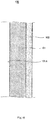
- Fig. 2 is a cross-sectional view of major constituents of the fuel tank of Fig. 1.
- Fig. 1 shows the internal structure (fuel tank) of the rocket, with a part of the rocket cut away.
- a fuel tank 100 is placed inside a rocket (spacecraft) 200, and is configured to store (reserve) therein liquid fuel (e.g., liquid oxygen or liquid hydrogen) with a low-temperature.
- the fuel tank 100 includes a carbon fiber reinforced plastic layer 101, and a metallic plating layer 102.
- the fuel tank 100 includes a cylindrical body 100A, a first lid member 100B with a circular plate shape, which closes a first opening end of the body 100A, and a second lid member 100C with a circular plate shape, which closes a second opening end of the body 100A.
- the carbon fiber reinforced plastic layer 101 has a surface 101A which is a polished surface having been subjected to polishing processing (treatment) on an inner side of the fuel tank 100 so that the surface 101A has a first predetermined surface roughness (degree).
- the surface 101A of the carbon fiber reinforced plastic layer 101 is provided with the metallic plating layer 102 formed by plating processing.
- a surface 102A of the metallic plating layer 102 forms the inner surface of the fuel tank 100.
- metal constituting the metallic plating layer 102 for example, at least one metal selected from a metal group including platinum, gold, silver, copper, nickel, chrome, zinc, tin, aluminum, and cadmium, or alloy of these metals may be used.
- non-electrolytic (electroless) plating may be performed, electroplating may be performed, or the non-electrolytic plating may be performed and then the electroplating may be performed.
- electroplating may be performed, or the non-electrolytic plating may be performed and then the electroplating may be performed.
- non-electrolytic nickel plating is performed and then copper electroplating is performed.
- the thickness of the metallic plating layer 102 may be set to 100 ⁇ m or less, or 50 ⁇ m or less. Alternatively, to prevent a situation in which vaporized liquid fuel leaks to outside of the fuel tank 100 through the carbon fiber reinforced plastic layer 101, the thickness of the metallic plating layer 102 may be set to a value in a range of 10 to 20 ⁇ m. Further, the metallic plating layer 102 may consist of a single plating layer or may include two or more plating layers.
- Fig. 3 is a schematic view showing the steps of a manufacturing method of the fuel tank according to Embodiment 1.
- an operator or the like manufactures the carbon fiber reinforced plastic layer 101 of the fuel tank 100 (step S101).
- the carbon fiber reinforced plastic layer 101 is manufactured by a known manufacturing method of carbon fiber reinforced plastic.
- the body 100A is manufactured in such a manner that prepreg clothes or prepreg sheets comprising carbon fibers which are impregnated with a phenol resin, a bismaleimide resin, a polyether ether ketone resin, a polyether ketone ketone resin, an epoxy resin or the like are laminated (stacked together), and a laminate with a cylindrical shape is hot-pressed or autoclaved.
- the first lid member 100B and the second lid member 100C are manufactured in such a manner that prepreg clothes or prepreg sheets impregnated with a resin are laminated (stacked together), and a laminate with a cylindrical shape is hot-pressed or autoclaved.
- the operator or the like performs polishing processing to the surface of the carbon fiber reinforced plastic layer 101 (to be precise, the body 100A, the first lid member 100B, and the second lid member 100C) manufactured in step S101 (step S102).
- the operator or the like performs the polishing processing by use of a polishing (abrasive) instrument.
- the polishing instrument used may be as follows. To allow the surface 100A to have the first predetermined surface roughness (degree), sandpaper, a polishing cloth sheet, or a resin sheet coated with a polishing agent, which has a count of 200 or more may be used.
- sandpaper, a polishing cloth sheet, or a resin sheet coated with a polishing agent which has a count of 2000 or less may be used, sandpaper or the like with a count of 1200 or less may be used, sandpaper or the like with a count of 1000 or less may be used, or sandpaper or the like with a count of 600 or less may be used.
- the operator or the like may perform the polishing processing to the surface 101A of the carbon fiber reinforced plastic layer 101 by use of the sandpaper or the like so that the surface 101A has the first predetermined surface roughness while measuring the surface roughness by use of a surface roughness measurement unit. Further, parameters of a direction, a pressure, and time of application of the sandpaper or the like, which allow the surface 101A to have the first predetermined surface roughness, may be found in advance by conducting an experiment, and the operator or the like may perform the polishing processing according to the parameters.
- polishing processing may be different from the polishing processing performed by use of the sandpaper or the like.
- chemical polishing processing or buffing processing may be performed.
- the surface roughness (degree) may be measured by use of, for example, a contact-type roughness meter, an atomic force microscope, a white-light interferometer, or a laser microscope.
- the operator or the like performs the plating processing to form the metallic plating layer 102 on the surface 101A of the carbon fiber reinforced plastic layer 101, the surface 101A having been subjected to the polishing processing (step S103).
- the operator or the like may perform the non-electrolytic (electroless) nickel plating and then perform copper electroplating.
- the operator or the like may perform the plating processing so that the metallic plating layer 102 has a thickness of 100 ⁇ m or less, or 50 ⁇ m or less.
- the operator or the like performs the non-electrolytic plating and then performs the electroplating, this is merely exemplary.
- the operator or the like may perform only the non-electrolytic plating, or only the electroplating.
- step S104 manufactures the fuel tank 100 (assembles: step S104). Specifically, the operator or the like assembles the fuel tank 100 in such a manner that the operator or the like places the first lid member 100B and the second lid member 100C in an opening of the body 100A, and joins them to each other by a suitable joining means (e.g., adhesive).
- a suitable joining means e.g., adhesive
- the metallic plating layer 102 is formed on the surface 101A of the carbon fiber reinforced plastic layer 101, the surface 101A having been subjected to the polishing processing so that the surface 101A has the first predetermined surface roughness.
- the surface 102A of the metallic plating layer 102 has a surface roughness which is close to or less than the first predetermined surface roughness. In this way, the inner surface of the fuel tank 100 is smoothed.
- a test for resistance to ignition of the fuel tank 100 may be conducted by use of ABMA impact test machine according to a test method standard (D2512-95) of ASTM (American Society for Testing and Materials).
- the thickness of the metallic plating layer 102 is set to 100 ⁇ m or less, which is less than that of the conventional fuel tank. In this structure, the weight of the fuel tank 100 according to Embodiment 1 can be reduced, compared to the conventional fuel tank.
- the surface 101A of the carbon fiber reinforced plastic layer 101 is the polished surface
- each of the surface 101A of the carbon fiber reinforced plastic layer 101 and the surface 102A of the metallic plating layer 102 may be polished so that each of the carbon fiber reinforced plastic layer 101 and the metallic plating layer 102 has the polished surface.
- the surface 102A of the metallic plating layer 102 may be polished by use of a polishing instrument.
- the fuel tank for use with the spacecraft according to Modified Example 1 of Embodiment 1 further includes a metallic plating layer covering a surface of the carbon fiber reinforced plastic layer, the surface being on an outer side of the fuel tank.
- a method of manufacturing a fuel tank for use with a spacecraft is a manufacturing method of a fuel tank for use with a spacecraft, the fuel tank including a carbon fiber reinforced plastic layer, the method comprising: (A) performing polishing processing to a surface of the carbon fiber reinforced plastic layer; (B2) forming metallic plating layers on the surface of the carbon fiber reinforced plastic layer, the surface having been subjected to the polishing processing, and a surface of the carbon fiber reinforced plastic layer, the surface being on a side opposite to the surface having been subjected to the polishing processing, after (A), and (C2) manufacturing the fuel tank for use with the spacecraft by placing the carbon fiber reinforced plastic layer so that the metallic plating layer formed on the surface of the carbon fiber reinforced plastic layer, the surface having been subjected to the polishing processing, is located on an inner side of the fuel tank, after (B2).
- the surface of the carbon fiber reinforced plastic layer may be polished by use of a polishing instrument with a count of 200 to 2000.
- the plating processing may be performed so that the metallic plating layer has a thickness of 100 ⁇ m or less.
- non-electrolytic (electroless) nickel plating may be performed and then copper plating may be performed.
- Fig. 4 is a cross-sectional view of major constituents of the fuel tank according to Modified Example 1 of Embodiment 1.
- the configuration of the fuel tank 100 according to Modified Example 1 is basically the same as that of the fuel tank 100 according to Embodiment 1, and is different from the same in that a metallic plating layer 103 is formed on a surface 101B of the carbon fiber reinforced plastic layer 101, the surface being on an outer side of the fuel tank 100.
- the configuration of the metallic plating layer 103 is the same as that of the metallic plating layer 102 of the fuel tank 100 according to Embodiment 1, and detailed description thereof is omitted.
- Fig. 5 is a schematic view showing the steps of a manufacturing method of the fuel tank according to Modified Example 1 of Embodiment 1.
- the manufacturing method of the fuel tank 100 according to Modified Example 1 is basically the same as the manufacturing method of the fuel tank 100 according to Embodiment 1, and is different from the same in that step S103A is performed instead of step S103.
- the operator or the like forms the metallic plating layer 102 on the polished surface 101A of the carbon fiber reinforced plastic layer 101, and forms the metallic plating layer 103 on the surface 101B of the carbon fiber reinforced plastic layer 101. More specifically, the operator or the like performs the non-electrolytic (electroless) nickel plating and then perform copper electroplating. At this time, the operator or the like may perform the plating processing so that the metallic plating layer 102 or the metallic plating layer 103 has a thickness of 100 ⁇ m or less, or 50 ⁇ m or less.
- the operator or the like performs the non-electrolytic plating and then performs the electroplating, this is merely exemplary.
- the operator or the like may perform only the non-electrolytic plating, or only the electroplating.
- the fuel tank 100 according to Modified Example 1 configured as described above can obtain the advantages as those of the fuel tank 100 according to Embodiment 1.
- the metallic plating layer 103 is formed on the outer side of the fuel tank 100. In a case where the metallic plating layer 102 has a slight flaw, or a part of the metallic plating layer 102 is not plated , leakage of a fuel gas can be reduced.
- a fuel tank for use with a spacecraft is a fuel tank for use with a spacecraft, the fuel tank being configured to store therein fuel for driving the spacecraft, the fuel tank comprising: a carbon fiber reinforced plastic layer and a metallic plating layer, wherein the carbon fiber reinforced plastic layer has a polished surface having been subjected to polishing processing, the polished surface being on an inner side of the fuel tank, and the metallic plating layer is provided on a surface of the carbon fiber reinforced plastic layer, the surface being on an outer side of the fuel tank.
- the polishing processing may be processing performed by use of a polishing instrument with a count of 200 to 2000.
- the metallic plating layer may have a thickness of 100 ⁇ m or less.
- the metallic plating layer may be formed by performing non-electrolytic (electroless) nickel plating and then performing copper plating.
- a method of manufacturing a fuel tank for use with a spacecraft is a manufacturing method of a fuel tank for use with a spacecraft, the fuel tank including a carbon fiber reinforced plastic layer, the method comprising: (A) performing polishing processing to a surface of the carbon fiber reinforced plastic layer; (B1) forming a metallic plating layer on a surface of the carbon fiber reinforced plastic layer, the surface being on a side opposite to the surface having been subjected to the polishing processing, after (A), and (C1) manufacturing the fuel tank for use with the spacecraft by placing the carbon fiber reinforced plastic layer so that the metallic plating layer is located on an outer side of the fuel tank, after (B1).
- the surface of the carbon fiber reinforced plastic layer may be polished by use of a polishing instrument with a count of 200 to 2000.
- the plating processing may be performed so that the metallic plating layer has a thickness of 100 ⁇ m or less.
- non-electrolytic (electroless) nickel plating may be performed and then copper plating may be performed.
- Fig. 6 is a cross-sectional view of major constituents of a fuel tank according to Embodiment 2.
- the configuration of the fuel tank 100 according to Embodiment 2 is basically the same as that of the fuel tank 100 according to Embodiment 1, and is different from the same in that the metallic plating layer 103 is formed on an outer side of the fuel tank 100, instead of the metallic plating layer 102 formed on an inner side of the fuel tank 100. Since the configuration of the metallic plating layer 103 is the same as that of the metallic plating layer 103 of the fuel tank 100 according to Modified Example 1 of Embodiment 1, and detailed description thereof is omitted.
- Fig. 7 is a schematic view showing the steps of a manufacturing method of the fuel tank according to Embodiment 2.
- the manufacturing method of the fuel tank 100 according to Embodiment 2 is basically the same as the manufacturing method of the fuel tank 100 according to Embodiment 1, and is different from the same in that step S103B is performed instead of step S103.
- the operator or the like forms the metallic plating layer 103 on the surface 101B of the carbon fiber reinforced plastic layer 101.
- the forming method of the metallic plating layer 103 is the same as that of the metallic plating layer 103 of the fuel tank 100 according to Modified Example 1 of Embodiment 1, and detailed description thereof is omitted.
- the surface 101A of the carbon fiber reinforced plastic layer 101 has been subjected to the polishing processing so that the surface 101A has the first predetermined surface roughness.
- the inner surface of the fuel tank 100 is smoothed.
- the thickness of the metallic plating layer 103 is set to 100 ⁇ m or less, which is less than that of the conventional fuel tank. In this structure, the weight of the fuel tank 100 according to Embodiment 2 can be reduced, compared to the conventional fuel tank.
- a fuel tank for use with a spacecraft is a fuel tank for use with a spacecraft, the fuel tank being configured to store therein fuel for driving the spacecraft, the fuel tank comprising: a carbon fiber reinforced plastic layer and a metallic plating layer covering a surface of the carbon fiber reinforced plastic layer, the surface being on an inner side of the fuel tank, wherein the metallic plating layer has a polished surface having been subjected to polishing processing, the polished surface being on an inner side of the fuel tank.
- the polishing processing may be buffing processing.
- the polishing processing may be processing performed by use of a polishing instrument with a count of 200 to 2000.
- the metallic plating layer may have a thickness of 100 ⁇ m or less.
- the metallic plating layer may be formed by performing non-electrolytic (electroless) nickel plating and then performing copper plating.
- a method of manufacturing a fuel tank for use with a spacecraft is a manufacturing method of a fuel tank for use with a spacecraft, the fuel tank including a carbon fiber reinforced plastic layer, the method comprising: (D) forming a metallic plating layer on a surface of the carbon fiber reinforced plastic layer, (E) performing polishing processing to the metallic plating layer, after (D), and (F) manufacturing the fuel tank for use with the spacecraft by placing the carbon fiber reinforced plastic layer so that the surface having been subjected to the polishing processing is located on an inner side of the fuel tank, after (E).
- the plating processing may be performed so that the metallic plating layer has a thickness of 100 ⁇ m or less.
- non-electrolytic nickel plating may be performed and then copper plating may be performed.
- the metallic plating layer may be buffed (buffing processing may be performed to the metallic plating layer).
- the metallic plating layer may be polished by use of a polishing instrument with a count of 200 to 2000.
- Fig. 8 is a cross-sectional view of major constituents of the fuel tank according to Embodiment 3.
- the configuration of the fuel tank 100 according to Embodiment 3 is basically the same as that of the fuel tank 100 according to Embodiment 1, and is different from the same in that the surface 102A of the metallic plating layer 102 is a polished surface having been subjected to polishing processing (the surface 101A of the carbon fiber reinforced plastic layer 101 is not the polished surface).
- the surface 102A of the metallic plating layer 102 has been subjected to the polishing processing to have a second predetermined surface roughness (degree).
- the polishing processing for example, the buffing processing, the chemical polishing processing, or the polishing processing by use of a polishing instrument may be used.
- the polishing instrument used is as follows. To allow the surface 101A to have the second predetermined surface roughness, sandpaper, a polishing cloth sheet, or a resin sheet coated with a polishing agent, which has a count of 200 or more may be used.
- sandpaper, a polishing cloth sheet, or a resin sheet coated with a polishing agent which has a count of 2000 or less may be used, sandpaper or the like with a count of 1200 or less may be used, sandpaper or the like with a count of 1000 or less may be used, or sandpaper or the like with a count of 600 or less may be used.
- the operator or the like may perform the polishing processing to the surface 102A by use of, for example, a buffing processing instrument or sandpaper, while measuring the surface roughness so that the surface 102A has the second predetermined surface roughness.
- the operator or the like may perform the polishing processing so that the metallic plating layer 102 has a thickness of 10 to 100 ⁇ m.
- the operator or the like may perform the polishing processing up to the surface 101A of the carbon fiber reinforced plastic layer 101 by scraping the metallic plating layer 102.
- the second predetermined surface roughness may be equal to or may be different from the first predetermined surface roughness.
- plating processing may be performed again.
- the plating processing may be performed so that the metallic plating layer 102 has a thickness of 100 ⁇ m or less.
- Fig. 9 is a schematic view showing the steps of a manufacturing method of the fuel tank according to Embodiment 3.
- the operator or the like manufactures the carbon fiber reinforced plastic layer 101 of the fuel tank 100 (step S101), as in the manufacturing method of the fuel tank 100 according to Embodiment 1.
- the operator or the like performs the plating processing to form the metallic plating layer 102 on the surface 101A of the carbon fiber reinforced plastic layer 101 (step S102C). Specifically, the operator or the like may perform the non-electrolytic nickel plating and then perform copper electroplating. At this time, the operator or the like may perform the plating processing so that the metallic plating layer 102 has a thickness of 100 ⁇ m or less, or may perform the plating processing to form the metallic plating layer 102 with a larger thickness and then may reduce the thickness of the metallic plating layer 102 to 100 ⁇ m or less by the polishing processing which is performed later.
- the operator or the like performs the non-electrolytic plating and then performs the electroplating, this is merely exemplary.
- the operator or the like may perform only the non-electrolytic plating, or only the electroplating.
- step S103C the operator or the like performs the polishing processing to the surface 102A of the metallic plating layer 102 formed in step S102C (step S103C). Specifically, for example, the operator or the like polishes the surface 102A of the metallic plating layer 102 by use of a buffing processing instrument.
- the operator or the like may polish the surface 102A of the metallic plating layer 102 by use of the sandpaper or the like.
- the operator or the like may polish the metallic plating layer 102 so that the metallic plating layer 102 has a thickness of 10 to 100 ⁇ m or may polish the metallic plating layer 102 so that the metallic plating layer 102 has a thickness of 10 to 50 ⁇ m.
- the operator or the like may perform the polishing processing up to the surface 101A of the carbon fiber reinforced plastic layer 101 by scraping the metallic plating layer 102. In this case, the operator or the like may perform the plating processing again to form the metallic plating layer 102.
- step S104 the operator or the like manufactures the fuel tank 100 (assembles: step S104).
- the metallic plating layer 102 is formed to have the second predetermined surface roughness (degree). Therefore, the inner surface of the fuel tank 100 is smoothed.
- the thickness of the metallic plating layer 102 is set to 100 ⁇ m or less, which is less than that of the conventional fuel tank. In this structure, the weight of the fuel tank 100 according to Embodiment 3 can be reduced, compared to the conventional fuel tank.
- the metallic plating layer is formed on the outer side of the fuel tank in addition to the inner side of the fuel tank.
- a method of manufacturing a fuel tank for use with a spacecraft is a manufacturing method of a fuel tank for use with a spacecraft, the fuel tank including a carbon fiber reinforced plastic layer, the method comprising: (D1) forming metallic plating layers on both surfaces, respectively, of the carbon fiber reinforced plastic layer, (E1) performing polishing processing to one of the metallic plating layers, after (D1), and (F) manufacturing the fuel tank for use with the spacecraft by placing the carbon fiber reinforced plastic layer so that the metallic plating layer having been subjected to the polishing processing is located on an inner side of the fuel tank, after (E1).
- the plating processing may be performed so that the metallic plating layer has a thickness of 100 ⁇ m or less.
- non-electrolytic nickel plating may be performed and then copper plating may be performed.
- the metallic plating layer may be buffed (buffing processing may be performed to the metallic plating layer).
- the metallic plating layer may be polished by use of a polishing instrument with a count of 200 to 2000.
- Fig. 10 is a cross-sectional view of major constituents of the fuel tank according to Modified Example 1 of Embodiment 3.
- the configuration of the fuel tank 100 according to Modified Example 1 is basically the same as that of the fuel tank 100 according to Embodiment 3, and is different from the same in that the metallic plating layer 103 is formed on the surface 101B on the outer side of the fuel tank 100.
- the configuration of the metallic plating layer 103 is the same as that of the metallic plating layer 103 of the fuel tank 100 according to Modified Example 1 of Embodiment 1, and detailed description thereof is omitted.
- Fig. 11 is a schematic view showing the steps of a manufacturing method of the fuel tank according to Modified Example 1 of Embodiment 3.
- the manufacturing method of the fuel tank 100 according to Modified Example 1 is basically the same as the manufacturing method of the fuel tank 100 according to Embodiment 3, and is different from the same in that step S102D is performed instead of step S102C.
- the operator or the like forms the metallic plating layer 102 on the surface 101A of the carbon fiber reinforced plastic layer 101, and forms the metallic plating layer 103 on the surface 101B of the carbon fiber reinforced plastic layer 101.
- the forming method of the metallic plating layer 103 is the same as that of the metallic plating layer 103 of the fuel tank 100 according to Modified Example 1 of Embodiment 1, and detailed description thereof is omitted.
- the fuel tank 100 according to Modified Example 1 configured as described above can obtain the advantages as those of the fuel tank 100.
- the metallic plating layer 103 is formed on the outer side of the fuel tank 100. In a case where the metallic plating layer 102 has a slight flaw, or a part of the metallic plating layer 102 is not plated, leakage of a fuel gas can be reduced.
- a fuel tank for use with a spacecraft (fuel tank for spacecraft) according to Embodiment 4 is a fuel tank for use with a spacecraft, the fuel tank being configured to store therein fuel for driving the spacecraft, the fuel tank comprising: a carbon fiber reinforced plastic layer and a metallic plating layer covering a surface of the carbon fiber reinforced plastic layer, the surface being on an inner side of the fuel tank, wherein the metallic plating layer has a thickness of 100 ⁇ m or less.
- the metallic plating layer may be formed by performing the non-electrolytic (electroless) nickel plating and then performing copper plating.
- a method of manufacturing a fuel tank for use with a spacecraft is a manufacturing method of a fuel tank for use with a spacecraft, the fuel tank including a carbon fiber reinforced plastic layer, the method comprising: (G) forming a metallic plating layer with a thickness of 100 ⁇ m or less on a surface of the carbon fiber reinforced plastic layer, and (H) manufacturing the fuel tank for use with the spacecraft by placing the carbon fiber reinforced plastic layer so that the surface formed with the metallic plating layer is located on an inner side of the fuel tank, after (G).
- non-electrolytic (electroless) nickel plating may be performed and then copper plating may be performed.
- Fig. 12 is a cross-sectional view of major constituents of the fuel tank according to Embodiment 4.
- the configuration of the fuel tank 100 according to Embodiment 4 is basically the same as that of the fuel tank 1 00 according to Embodiment 1, and is different from the same in that the surface 101A of the carbon fiber reinforced plastic layer 101 has not been subjected to the polishing processing (the surface 101A is not the polished surface)
- Fig. 13 is a schematic view showing the steps of a manufacturing method of the fuel tank according to Embodiment 4.
- the operator or the like manufactures the carbon fiber reinforced plastic layer 101 of the fuel tank 100 (step S101), as in the manufacturing method of the fuel tank 100 according to Embodiment 1.
- the operator or the like performs the plating processing to form the metallic plating layer 102 on the surface 101A of the carbon fiber reinforced plastic layer 101 (step S102E). Specifically, the operator or the like may perform the non-electrolytic nickel plating and then perform copper electroplating. At this time, the operator or the like may perform the plating processing so that the metallic plating layer 102 has a thickness of 100 ⁇ m or less, or 50 ⁇ m or less.
- the operator or the like performs the non-electrolytic (electroless) plating and then performs the electroplating, this is merely exemplary.
- the operator or the like may perform only the non-electrolytic plating, or only the electroplating.
- step S104 the operator or the like manufactures the fuel tank 100 (assembles: step S104).
- the thickness of the metallic plating layer 102 is set to 100 ⁇ m or less, which is less than that of the conventional fuel tank. In this structure, the weight of the fuel tank 100 according to Embodiment 4 can be reduced, compared to the conventional fuel tank.
- the metallic plating layer is formed on the outer side of the fuel tank in addition to the inner side of the fuel tank.
- a method of manufacturing a fuel tank for use with a spacecraft is a manufacturing method of a fuel tank for use with a spacecraft, the fuel tank including a carbon fiber reinforced plastic layer, the method comprising: (G2) forming metallic plating layers with a thickness of 100 ⁇ m or less on both surfaces, respectively, of the carbon fiber reinforced plastic layer, and (H2) manufacturing the fuel tank for use with the spacecraft by placing the carbon fiber reinforced plastic layer.
- non-electrolytic (electroless) nickel plating may be performed and then copper plating may be performed.
- Fig. 14 is a cross-sectional view of major constituents of a fuel tank according to Modified Example 1 of Embodiment 4.
- the configuration of the fuel tank 100 according to Modified Example 1 is basically the same as that of the fuel tank 100 according to Embodiment 4, and is different from the same in that the metallic plating layer 103 is formed on the surface 101B on the outer side of the fuel tank 100, in addition to the metallic plating layer 102 formed on the surface 101A on the inner side of the fuel tank 100. Since the configuration of the metallic plating layer 103 is the same as that of the metallic plating layer 103 of the fuel tank 100 according to Modified Example 1 of Embodiment 1, and detailed description thereof is omitted.
- Fig. 15 is a schematic view showing the steps of a manufacturing method of the fuel tank according to Modified Example 1 of Embodiment 4.
- the manufacturing method of the fuel tank 100 according to Modified Example 1 is basically the same as the manufacturing method of the fuel tank 100 according to Embodiment 4, and is different from the same in that step S102F is performed instead of step S102E.
- the operator or the like forms the metallic plating layer 102 on the surface 101A of the carbon fiber reinforced plastic layer 101, and forms the metallic plating layer 103 on the surface 101B of the carbon fiber reinforced plastic layer 101.
- the forming method of the metallic plating layer 103 is the same as that of the metallic plating layer 103 of the fuel tank 100 according to Modified Example 1 of Embodiment 1, and detailed description thereof is omitted.
- the fuel tank 100 according to Modified Example 1 configured as described above can obtain the advantages as those of the fuel tank 100 according to Embodiment 4.
- the metallic plating layer 103 is formed on the outer side of the fuel tank 100. In a case where the metallic plating layer 102 has a slight flaw, or a part of the metallic plating layer 102 is not plated, leakage of a fuel gas can be reduced.
- a fuel tank for use with a spacecraft (fuel tank for spacecraft) according to Embodiment 5 is a fuel tank for use with a spacecraft, the fuel tank being configured to store therein fuel for driving the spacecraft, the fuel tank comprising: a carbon fiber reinforced plastic layer and a metallic plating layer covering a surface of the carbon fiber reinforced plastic layer, the surface being on an outer side of the fuel tank, and the metallic plating layer has a thickness of 100 ⁇ m or less.
- the metallic plating layer may be formed by performing non-electrolytic (electroless) nickel plating and then performing copper plating.
- a method of manufacturing a fuel tank for use with a spacecraft is a manufacturing method of a fuel tank for use with a spacecraft, the fuel tank including a carbon fiber reinforced plastic layer, the method comprising: (G1) forming a metallic plating layer with a thickness of 100 ⁇ m or less, on a surface of the carbon fiber reinforced plastic layer, and (H1) manufacturing the fuel tank for use with the spacecraft by placing the carbon fiber reinforced plastic layer so that the surface formed with the metallic plating layer is located on an outer side of the fuel tank, after (G1).
- non-electrolytic (electroless) nickel plating may be performed and then copper plating may be performed.
- a fuel tank for use with the spacecraft (hereinafter will be simply referred to as a fuel tank) according to Embodiment 5 will be described with reference to Figs. 16 and 17 .
- Fig. 16 is a cross-sectional view of major constituents of a fuel tank according to Embodiment 5.
- the configuration of the fuel tank 100 according to Embodiment 5 is basically the same as that of the fuel tank 100 according to Embodiment 4, and is different from the same in that the metallic plating layer 103 is formed on the outer side of the fuel tank 100, instead of the metallic plating layer 102 formed on the inner side of the fuel tank 100.
- Fig. 17 is a schematic view showing the steps of a manufacturing method of the fuel tank according to Embodiment 5.
- the operator or the like manufactures the carbon fiber reinforced plastic layer 101 of the fuel tank 100 (step S101), as in the manufacturing method of the fuel tank 100 according to Embodiment 1.
- the operator or the like performs the plating processing to form the metallic plating layer 103 on the surface 101B of the carbon fiber reinforced plastic layer 101 (step S102G). Specifically, the operator or the like may perform the non-electrolytic nickel plating and then perform copper electroplating. At this time, the operator or the like may perform the plating processing so that the metallic plating layer 103 has a thickness of 100 ⁇ m or less, or 50 ⁇ m or less.
- the operator or the like performs the non-electrolytic (electroless) plating and then performs the electroplating, this is merely exemplary.
- the operator or the like may perform only the non-electrolytic plating, or only the electroplating.
- step S104 the operator or the like manufactures the fuel tank 100 (assembles: step S104).
- the thickness of the metallic plating layer 103 is set to 100 ⁇ m or less, which is less than that of the conventional fuel tank. In this structure, the weight of the fuel tank 100 according to Embodiment 5 can be reduced, compared to the conventional fuel tank.
- a fuel tank for use with a spacecraft and a manufacturing method thereof, of the present invention are able to improve resistance to ignition in a liquid oxygen ambience, and therefore are useful.
Landscapes
- Chemical & Material Sciences (AREA)
- Engineering & Computer Science (AREA)
- Chemical Kinetics & Catalysis (AREA)
- Materials Engineering (AREA)
- Metallurgy (AREA)
- Organic Chemistry (AREA)
- Mechanical Engineering (AREA)
- General Chemical & Material Sciences (AREA)
- Electrochemistry (AREA)
- Remote Sensing (AREA)
- Combustion & Propulsion (AREA)
- Aviation & Aerospace Engineering (AREA)
- Composite Materials (AREA)
- Textile Engineering (AREA)
- Inorganic Chemistry (AREA)
- Physics & Mathematics (AREA)
- Thermal Sciences (AREA)
- Electroplating Methods And Accessories (AREA)
- Chemically Coating (AREA)
- Laminated Bodies (AREA)
- Moulding By Coating Moulds (AREA)
Abstract
Description
- The present invention relates to a fuel tank for use with a spacecraft (fuel tank for spacecraft), and a manufacturing method thereof.
- To reduce the weight of a pressure container (pressure vessel) mounted in an aerospace vehicle (payload) in which an artificial satellite or the like is mounted, a manufacturing method of a composite pressure container (vessel) is known, in which the thickness of a metal layer is reduced (e.g., see Patent Literature 1). In the manufacturing method of the composite pressure container disclosed in Patent Literature 1, the weight of the pressure container for storing helium therein is reduced.
- Patent Literature 1: Japanese Laid-Open Patent Application Publication No.
2002-139197 - However, in the composite pressure container disclosed in the above-described Patent Literature 1, there is a room for improvement in reduction of the weight of the pressure container.
- In the manufacturing method of the composite pressure container disclosed in the above-described Patent Literature 1, consideration is not given to a case where liquid oxygen is stored in the manufactured composite pressure container. Therefore, there is a room for improvement in resistance to ignition in a liquid oxygen ambience.
- An object of the present invention is to provide a fuel tank for use with a spacecraft, and a manufacturing method thereof, which can solve at least one of the above-described two problems.
- According to the present invention, there is provided a fuel tank for use with a spacecraft, the fuel tank being configured to store therein fuel for driving the spacecraft, the fuel tank comprising: a carbon fiber reinforced plastic layer and a metallic plating layer, wherein the carbon fiber reinforced plastic layer has a polished surface having been subjected to polishing processing, the polished surface being on an inner side of the fuel tank, and wherein the metallic plating layer is provided on the polished surface.
- In this configuration, the inner surface of the fuel tank for use with the spacecraft (fuel tank for spacecraft) is smoothed. Even in a case where liquid oxygen is stored in the fuel tank for use with the spacecraft, resistance to ignition in a liquid oxygen ambience can be improved.
- According to the present invention, there is provided a fuel tank for use with a spacecraft, the fuel tank being configured to store therein fuel for driving the spacecraft, the fuel tank comprising: a carbon fiber reinforced plastic layer and a metallic plating layer, wherein the carbon fiber reinforced plastic layer has a polished surface having been subjected to polishing processing, the polished surface being on an inner side of the fuel tank, and wherein the metallic plating layer is provided on an outer side of the fuel tank.
- In this configuration, the inner surface of the fuel tank for use with the spacecraft (fuel tank for spacecraft) is smoothed. Even in a case where liquid oxygen is stored in the fuel tank for use with the spacecraft, resistance to ignition in a liquid oxygen ambience can be improved.
- According to the present invention, there is provided a fuel tank for use with a spacecraft, the fuel tank being configured to store therein fuel for driving the spacecraft, the fuel tank comprising: a carbon fiber reinforced plastic layer and metallic plating layers, wherein the carbon fiber reinforced plastic layer has a polished surface having been subjected to polishing processing, the polished surface being on an inner side of the fuel tank, and wherein the metallic plating layers are provided on the polished surface and on a surface of the carbon fiber reinforced plastic layer, the surface being an outer side of the fuel tank.
- In this configuration, the inner surface of the fuel tank for use with the spacecraft (fuel tank for spacecraft) is smoothed. Even in a case where liquid oxygen is stored in the fuel tank for use with the spacecraft, resistance to ignition in a liquid oxygen ambience can be improved.
- According to the present invention, there is provided a fuel tank for use with a spacecraft, the fuel tank being configured to store therein fuel for driving the spacecraft, the fuel tank comprising: a carbon fiber reinforced plastic layer; and a metallic plating layer covering a surface of the carbon fiber reinforced plastic layer, the surface being on an inner side of the fuel tank, wherein the metallic plating layer has a polished surface having been subjected to polishing processing, the polished surface being on the inner side of the fuel tank.
- In this configuration, the inner surface of the fuel tank for use with the spacecraft (fuel tank for spacecraft) is smoothed. Even in a case where liquid oxygen is stored in the fuel tank for use with the spacecraft, resistance to ignition in a liquid oxygen ambience can be improved.
- According to the present invention, there is provided a fuel tank for use with a spacecraft, the fuel tank being configured to store therein fuel for driving the spacecraft, the fuel tank comprising: a carbon fiber reinforced plastic layer; a metallic plating layer covering a surface of the carbon fiber reinforced plastic layer, the surface being on an inner side of the fuel tank, and a metallic plating layer covering a surface of the carbon fiber reinforced plastic layer, the surface being on an outer side of the fuel tank, wherein the metallic plating layer covering the surface of the carbon fiber reinforced plastic layer, the surface being on the inner side of the fuel tank has a polished surface having been subjected to polishing processing.
- In this configuration, the inner surface of the fuel tank for use with the spacecraft (fuel tank for spacecraft) is smoothed. Even in a case where liquid oxygen is stored in the fuel tank for use with the spacecraft, resistance to ignition in a liquid oxygen ambience can be improved.
- According to the present invention, there is provided a fuel tank for use with a spacecraft, the fuel tank being configured to store therein fuel for driving the spacecraft, the fuel tank comprising: a carbon fiber reinforced plastic layer; and a metallic plating layer covering a surface of the carbon fiber reinforced plastic layer, the surface being on an inner side of the fuel tank, wherein the metallic plating layer has a thickness of 100µm or less.
- In this configuration, since the thickness of the metallic plating layer is reduced as compared to the conventional fuel tank, the weight of the fuel tank can be reduced.
- According to the present invention, there is provided a fuel tank for use with a spacecraft, the fuel tank being configured to store therein fuel for driving the spacecraft, the fuel tank comprising: a carbon fiber reinforced plastic layer; and a metallic plating layer covering a surface of the carbon fiber reinforced plastic layer, the surface being on an outer side of the fuel tank, wherein the metallic plating layer has a thickness of 100µm or less.
- In this configuration, since the thickness of the metallic plating layer is reduced as compared to the conventional fuel tank, the weight of the fuel tank can be reduced.
- According to the present invention, there is provided a fuel tank for use with a spacecraft, the fuel tank being configured to store therein fuel for driving the spacecraft, the fuel tank comprising: a carbon fiber reinforced plastic layer; and metallic plating layers covering a surface of the carbon fiber reinforced plastic layer, the surface being on an inner side of the fuel tank, and a surface of the carbon fiber reinforced plastic layer, the surface being on an outer side of the fuel tank, respectively, wherein the metallic plating layers have a thickness of 100µm or less.
- In this configuration, since the thickness of the metallic plating layer is reduced as compared to the conventional fuel tank, the weight of the fuel tank can be reduced.
- According to the present invention, there is provided a method of manufacturing a fuel tank for use with a spacecraft, the fuel tank including a carbon fiber reinforced plastic layer, the method comprising: (A) performing polishing processing to a surface of the carbon fiber reinforced plastic layer; (B) forming a metallic plating layer on the surface of the carbon fiber reinforced plastic layer, the surface having been subjected to the polishing processing, after (A); and (C) manufacturing the fuel tank for use with the spacecraft by placing the carbon fiber reinforced plastic layer so that the metallic plating layer is located on an inner side of the fuel tank, after (B).
- In this method, the inner surface of the fuel tank for use with the spacecraft (fuel tank for spacecraft) is smoothed. Even in a case where liquid oxygen is stored in the fuel tank for use with the spacecraft, resistance to ignition in a liquid oxygen ambience can be improved.
- According to the present invention, there is provided a method of manufacturing a fuel tank for use with a spacecraft, the fuel tank including a carbon fiber reinforced plastic layer, the method comprising: (A) performing polishing processing to a surface of the carbon fiber reinforced plastic layer; (B1) forming a metallic plating layer on a surface of the carbon fiber reinforced plastic layer, the surface being on a side opposite to the surface having been subjected to the polishing processing, after (A), and (C1) manufacturing the fuel tank for use with the spacecraft by placing the carbon fiber reinforced plastic layer so that the metallic plating layer is located on an outer side of the fuel tank, after (B1).
- In this method, the inner surface of the fuel tank for use with the spacecraft (fuel tank for spacecraft) is smoothed. Even in a case where liquid oxygen is stored in the fuel tank for use with the spacecraft, resistance to ignition in a liquid oxygen ambience can be improved.
- According to the present invention, there is provided a method of manufacturing a fuel tank for use with a spacecraft, the fuel tank including a carbon fiber reinforced plastic layer, the method comprising: (A) performing polishing processing to a surface of the carbon fiber reinforced plastic layer; (B2) forming metallic plating layers on the surface of the carbon fiber reinforced plastic layer, the surface having been subjected to the polishing processing, and a surface of the carbon fiber reinforced plastic layer, the surface being on a side opposite to the surface having been subjected to the polishing processing, after (A), and (C2) manufacturing the fuel tank for use with the spacecraft by placing the carbon fiber reinforced plastic layer so that the metallic plating layer formed on the surface of the carbon fiber reinforced plastic layer, the surface having been subjected to the polishing processing, is located on an inner side of the fuel tank, after (B2).
- In this method, the inner surface of the fuel tank for use with the spacecraft (fuel tank for spacecraft) is smoothed. Even in a case where liquid oxygen is stored in the fuel tank for use with the spacecraft, resistance to ignition in a liquid oxygen ambience can be improved.
- According to the present invention, there is provided a method of manufacturing a fuel tank for use with a spacecraft, the fuel tank including a carbon fiber reinforced plastic layer, the method comprising: (D) forming a metallic plating layer on a surface of the carbon fiber reinforced plastic layer; (E) performing polishing processing to the metallic plating layer, after (D): and (F) manufacturing the fuel tank for use with the spacecraft by placing the carbon fiber reinforced plastic layer so that the surface having been subjected to the polishing processing is located on an inner side of the fuel tank, after (E).
- In this method, the inner surface of the fuel tank for use with the spacecraft (fuel tank for spacecraft) is smoothed. Even in a case where liquid oxygen is stored in the fuel tank for use with the spacecraft, resistance to ignition in a liquid oxygen ambience can be improved.
- According to the present invention, there is provided a method of manufacturing a fuel tank for use with a spacecraft, the fuel tank including a carbon fiber reinforced plastic layer, the method comprising: (D1) forming metallic plating layers on both surfaces, respectively, of the carbon fiber reinforced plastic layer, (E1) performing polishing processing to one of the metallic plating layers, after (D1), and (F1) manufacturing the fuel tank for use with the spacecraft by placing the carbon fiber reinforced plastic layer so that the metallic plating layer having been subjected to the polishing processing is located on an inner side of the fuel tank, after (E1).
- In this method, the inner surface of the fuel tank for use with the spacecraft (fuel tank for spacecraft) is smoothed. Even in a case where liquid oxygen is stored in the fuel tank for use with the spacecraft, resistance to ignition in a liquid oxygen ambience can be improved.
- According to the present invention, there is provided a method of manufacturing a fuel tank for use with a spacecraft, the fuel tank including a carbon fiber reinforced plastic layer, the method comprising: (G) forming a metallic plating layer with a thickness of 100µm or less on a surface of the carbon fiber reinforced plastic layer; and (H) manufacturing the fuel tank for use with the spacecraft by placing the carbon fiber reinforced plastic layer so that the surface formed with the metallic plating layer is located on an inner side of the fuel tank, after (G).
- In this method, since the thickness of the metallic plating layer is reduced as compared to the conventional fuel tank, the weight of the fuel tank can be reduced.
- According to the present invention, there is provided a method of manufacturing a fuel tank for use with a spacecraft, the fuel tank including a carbon fiber reinforced plastic layer, the method comprising: (G1) forming a metallic plating layer with a thickness of 100µm or less, on a surface of the carbon fiber reinforced plastic layer; and (H1) manufacturing the fuel tank for use with the spacecraft by placing the carbon fiber reinforced plastic layer so that the surface formed with the metallic plating layer is located on an outer side of the fuel tank, after (G1).
- In this method, since the thickness of the metallic plating layer is reduced as compared to the conventional fuel tank, the weight of the fuel tank can be reduced.
- According to the present invention, there is provided a method of manufacturing a fuel tank for use with a spacecraft, the fuel tank including a carbon fiber reinforced plastic layer, the method comprising: (G2) forming metallic plating layers with a thickness of 100µm or less on both surfaces, respectively, of the carbon fiber reinforced plastic layer, and (H2) manufacturing the fuel tank for use with the spacecraft by placing the carbon fiber reinforced plastic layer.
- In this method, since the thickness of the metallic plating layer is reduced as compared to the conventional fuel tank, the weight of the fuel tank can be reduced.
- In accordance with a fuel tank for use with a spacecraft and a manufacturing method thereof, resistance to ignition in a liquid oxygen ambience can be improved. In addition, in accordance with a fuel tank for use with a spacecraft and a manufacturing method thereof, the weight of the fuel tank for use with the spacecraft can be reduced as compared to the conventional fuel tank for use with the spacecraft.
-
-
Fig. 1 is a schematic view showing a state in which a fuel tank according to Embodiment 1 is placed inside a rocket. -
Fig. 2 is a cross-sectional view of major constituents of the fuel tank ofFig. 1 . -
Fig. 3 is a schematic view showing the steps of a manufacturing method of the fuel tank according to Embodiment 1. -
Fig. 4 is a cross-sectional view of major constituents of a fuel tank according to Modified Example 1 of Embodiment 1. -
Fig. 5 is a schematic view showing the steps of a manufacturing method of the fuel tank according to Modified Example 1 of Embodiment 1. -
Fig. 6 is a cross-sectional view of major constituents of a fuel tank according to Embodiment 2. -
Fig. 7 is a schematic view showing the steps of a manufacturing method of the fuel tank according to Embodiment 2. -
Fig. 8 is a cross-sectional view of major constituents of a fuel tank according to Embodiment 3. -
Fig. 9 is a schematic view showing the steps of a manufacturing method of the fuel tank according to Embodiment 3. -
Fig. 10 is a cross-sectional view of major constituents of a fuel tank according to Modified Example 1 of Embodiment 3. -
Fig. 11 is a schematic view showing the steps of a manufacturing method of the fuel tank according to Modified Example 1 of Embodiment 3. -
Fig. 12 is a cross-sectional view of major constituents of a fuel tank according to Embodiment 4. -
Fig. 13 is a schematic view showing the steps of a manufacturing method of the fuel tank according to Embodiment 4. -
Fig. 14 is a cross-sectional view of major constituents of a fuel tank according to Modified Example 1 of Embodiment 4. -
Fig. 15 is a schematic view showing the steps of a manufacturing method of the fuel tank according to Modified Example 1 of Embodiment 4. -
Fig. 16 is a cross-sectional view of major constituents of a fuel tank according to Embodiment 5. -
Fig. 17 is a schematic view showing the steps of a manufacturing method of the fuel tank according to Embodiment 5. - Hereinafter, the embodiments of the present invention will be described with reference to the drawings. Throughout the drawings, the same or corresponding constituents are designated by the same reference symbols, and will not be described in repetition. Also, throughout the drawings, constituents required to describe the invention are extracted and shown, while the other constituents are sometimes omitted. Further, the present invention is not limited to the embodiments described below.
- A fuel tank for use with a spacecraft (fuel tank for spacecraft) according to Embodiment 1 is a fuel tank for use with a spacecraft, the fuel tank being configured to store therein fuel for driving the spacecraft, the fuel tank comprising: a carbon fiber reinforced plastic layer and a metallic plating layer, wherein the carbon fiber reinforced plastic layer has a polished surface having been subjected to polishing processing, the polished surface being on an inner side of the fuel tank, and the metallic plating layer is provided on the polished surface.
- In the fuel tank for use with the spacecraft according to Embodiment 1, the polishing processing may be processing performed by use of a polishing instrument with a count of 200 to 2000.
- In the fuel tank for use with the spacecraft according to Embodiment 1, the metallic plating layer may have a thickness of 100µm or less.
- In the fuel tank for use with the spacecraft according to Embodiment 1, the metallic plating layer may be formed by performing non-electrolytic (electroless) nickel plating and then performing copper plating.
- A method of manufacturing a fuel tank for use with a spacecraft, according to Embodiment 1, is a manufacturing method of a fuel tank for use with a spacecraft, the fuel tank including a carbon fiber reinforced plastic layer, the method comprising: (A) performing polishing processing to a surface of the carbon fiber reinforced plastic layer; (B) forming a metallic plating layer on the surface of the carbon fiber reinforced plastic layer, the surface having been subjected to the polishing processing, after (A), and (C) manufacturing the fuel tank for use with the spacecraft by placing the carbon fiber reinforced plastic layer so that the metallic plating layer is located on an inner side of the fuel tank, after (B).
- In the method of manufacturing the fuel tank for use with the spacecraft according to Embodiment 1, the surface of the carbon fiber reinforced plastic layer may be polished by use of a polishing instrument with a count of 200 to 2000.
- In the method of manufacturing the fuel tank for use with the spacecraft according to Embodiment 1, in (B), the plating processing may be performed so that the metallic plating layer has a thickness of 100µm or less.
- In the method of manufacturing the fuel tank for use with the spacecraft according to Embodiment 1, in (B), non-electrolytic (electroless) nickel plating may be performed and then copper plating may be performed.
- Hereinafter, an example of the fuel tank for use with the spacecraft (hereinafter will be simply referred to as a fuel tank) according to Embodiment 1 will be described with reference to
Figs. 1 to 3 . -
Fig. 1 is a schematic view showing a state in which a fuel tank according to Embodiment 1 is placed inside a rocket.Fig. 2 is a cross-sectional view of major constituents of the fuel tank ofFig. 1. Fig. 1 shows the internal structure (fuel tank) of the rocket, with a part of the rocket cut away. - As shown in
Figs. 1 and2 , afuel tank 100 according to Embodiment 1 is placed inside a rocket (spacecraft) 200, and is configured to store (reserve) therein liquid fuel (e.g., liquid oxygen or liquid hydrogen) with a low-temperature. Thefuel tank 100 includes a carbon fiber reinforcedplastic layer 101, and ametallic plating layer 102. In Embodiment 1, thefuel tank 100 includes acylindrical body 100A, afirst lid member 100B with a circular plate shape, which closes a first opening end of thebody 100A, and asecond lid member 100C with a circular plate shape, which closes a second opening end of thebody 100A. - The carbon fiber reinforced
plastic layer 101 has asurface 101A which is a polished surface having been subjected to polishing processing (treatment) on an inner side of thefuel tank 100 so that thesurface 101A has a first predetermined surface roughness (degree). Thesurface 101A of the carbon fiber reinforcedplastic layer 101 is provided with themetallic plating layer 102 formed by plating processing. Asurface 102A of themetallic plating layer 102 forms the inner surface of thefuel tank 100. - As metal constituting the
metallic plating layer 102, for example, at least one metal selected from a metal group including platinum, gold, silver, copper, nickel, chrome, zinc, tin, aluminum, and cadmium, or alloy of these metals may be used. - As the plating processing, non-electrolytic (electroless) plating may be performed, electroplating may be performed, or the non-electrolytic plating may be performed and then the electroplating may be performed. In Embodiment 1, non-electrolytic nickel plating is performed and then copper electroplating is performed.
- To reduce the weight of the
fuel tank 100, the thickness of themetallic plating layer 102 may be set to 100µm or less, or 50µm or less. Alternatively, to prevent a situation in which vaporized liquid fuel leaks to outside of thefuel tank 100 through the carbon fiber reinforcedplastic layer 101, the thickness of themetallic plating layer 102 may be set to a value in a range of 10 to 20µm. Further, themetallic plating layer 102 may consist of a single plating layer or may include two or more plating layers. -
Fig. 3 is a schematic view showing the steps of a manufacturing method of the fuel tank according to Embodiment 1. - As shown in
Fig. 3 , initially, an operator or the like manufactures the carbon fiber reinforcedplastic layer 101 of the fuel tank 100 (step S101). The carbon fiber reinforcedplastic layer 101 is manufactured by a known manufacturing method of carbon fiber reinforced plastic. - Specifically, for example, the
body 100A is manufactured in such a manner that prepreg clothes or prepreg sheets comprising carbon fibers which are impregnated with a phenol resin, a bismaleimide resin, a polyether ether ketone resin, a polyether ketone ketone resin, an epoxy resin or the like are laminated (stacked together), and a laminate with a cylindrical shape is hot-pressed or autoclaved. Thefirst lid member 100B and thesecond lid member 100C are manufactured in such a manner that prepreg clothes or prepreg sheets impregnated with a resin are laminated (stacked together), and a laminate with a cylindrical shape is hot-pressed or autoclaved. - Then, the operator or the like performs polishing processing to the surface of the carbon fiber reinforced plastic layer 101 (to be precise, the
body 100A, thefirst lid member 100B, and thesecond lid member 100C) manufactured in step S101 (step S102). Specifically, the operator or the like performs the polishing processing by use of a polishing (abrasive) instrument. The polishing instrument used may be as follows. To allow thesurface 100A to have the first predetermined surface roughness (degree), sandpaper, a polishing cloth sheet, or a resin sheet coated with a polishing agent, which has a count of 200 or more may be used. To reduce time required for the polishing processing, sandpaper, a polishing cloth sheet, or a resin sheet coated with a polishing agent, which has a count of 2000 or less may be used, sandpaper or the like with a count of 1200 or less may be used, sandpaper or the like with a count of 1000 or less may be used, or sandpaper or the like with a count of 600 or less may be used. - At this time, the operator or the like may perform the polishing processing to the
surface 101A of the carbon fiber reinforcedplastic layer 101 by use of the sandpaper or the like so that thesurface 101A has the first predetermined surface roughness while measuring the surface roughness by use of a surface roughness measurement unit. Further, parameters of a direction, a pressure, and time of application of the sandpaper or the like, which allow thesurface 101A to have the first predetermined surface roughness, may be found in advance by conducting an experiment, and the operator or the like may perform the polishing processing according to the parameters. - Note that the polishing processing may be different from the polishing processing performed by use of the sandpaper or the like. For example, chemical polishing processing or buffing processing may be performed. The surface roughness (degree) may be measured by use of, for example, a contact-type roughness meter, an atomic force microscope, a white-light interferometer, or a laser microscope.
- Next, the operator or the like performs the plating processing to form the
metallic plating layer 102 on thesurface 101A of the carbon fiber reinforcedplastic layer 101, thesurface 101A having been subjected to the polishing processing (step S103). Specifically, the operator or the like may perform the non-electrolytic (electroless) nickel plating and then perform copper electroplating. At this time, the operator or the like may perform the plating processing so that themetallic plating layer 102 has a thickness of 100µm or less, or 50µm or less. - Although in Embodiment 1, the operator or the like performs the non-electrolytic plating and then performs the electroplating, this is merely exemplary. For example, the operator or the like may perform only the non-electrolytic plating, or only the electroplating.
- Next, the operator or the like manufactures the fuel tank 100 (assembles: step S104). Specifically, the operator or the like assembles the
fuel tank 100 in such a manner that the operator or the like places thefirst lid member 100B and thesecond lid member 100C in an opening of thebody 100A, and joins them to each other by a suitable joining means (e.g., adhesive). - In the
fuel tank 100 according to Embodiment 1 configured as described above, themetallic plating layer 102 is formed on thesurface 101A of the carbon fiber reinforcedplastic layer 101, thesurface 101A having been subjected to the polishing processing so that thesurface 101A has the first predetermined surface roughness. In this structure, thesurface 102A of themetallic plating layer 102 has a surface roughness which is close to or less than the first predetermined surface roughness. In this way, the inner surface of thefuel tank 100 is smoothed. - For example, even in a case where an impact or the like is externally applied to the
fuel tank 100 storing the liquid oxygen therein, conversion of motion energy into heat energy can be suppressed in the inner surface of thefuel tank 100, and thus resistance to ignition in a liquid oxygen ambience can be improved. - For example, a test for resistance to ignition of the
fuel tank 100 may be conducted by use of ABMA impact test machine according to a test method standard (D2512-95) of ASTM (American Society for Testing and Materials). - In the
fuel tank 100 according to Embodiment 1, the thickness of themetallic plating layer 102 is set to 100µm or less, which is less than that of the conventional fuel tank. In this structure, the weight of thefuel tank 100 according to Embodiment 1 can be reduced, compared to the conventional fuel tank. - Although in the
fuel tank 100 according to Embodiment 1, thesurface 101A of the carbon fiber reinforcedplastic layer 101 is the polished surface, this is exemplary. For example, each of thesurface 101A of the carbon fiber reinforcedplastic layer 101 and thesurface 102A of themetallic plating layer 102 may be polished so that each of the carbon fiber reinforcedplastic layer 101 and themetallic plating layer 102 has the polished surface. In this case, after themetallic plating layer 102 is formed in step S103, thesurface 102A of themetallic plating layer 102 may be polished by use of a polishing instrument. - Next, a fuel tank for use with a spacecraft according to Modified Example 1 of Embodiment 1 will be described.
- The fuel tank for use with the spacecraft according to Modified Example 1 of Embodiment 1 further includes a metallic plating layer covering a surface of the carbon fiber reinforced plastic layer, the surface being on an outer side of the fuel tank.
- A method of manufacturing a fuel tank for use with a spacecraft, according to Modified Example 1 of Embodiment 1, is a manufacturing method of a fuel tank for use with a spacecraft, the fuel tank including a carbon fiber reinforced plastic layer, the method comprising: (A) performing polishing processing to a surface of the carbon fiber reinforced plastic layer; (B2) forming metallic plating layers on the surface of the carbon fiber reinforced plastic layer, the surface having been subjected to the polishing processing, and a surface of the carbon fiber reinforced plastic layer, the surface being on a side opposite to the surface having been subjected to the polishing processing, after (A), and (C2) manufacturing the fuel tank for use with the spacecraft by placing the carbon fiber reinforced plastic layer so that the metallic plating layer formed on the surface of the carbon fiber reinforced plastic layer, the surface having been subjected to the polishing processing, is located on an inner side of the fuel tank, after (B2).
- In the method of manufacturing the fuel tank for use with the spacecraft according to Modified Example 1 of Embodiment 1, in (A), the surface of the carbon fiber reinforced plastic layer may be polished by use of a polishing instrument with a count of 200 to 2000.
- In the method of manufacturing the fuel tank for use with the spacecraft according to Modified Example 1 of Embodiment 1, in (B2), the plating processing may be performed so that the metallic plating layer has a thickness of 100µm or less.
- In the method of manufacturing the fuel tank for use with the spacecraft according to Modified Example 1 of Embodiment 1, in (B2), non-electrolytic (electroless) nickel plating may be performed and then copper plating may be performed.
- Hereinafter, an example of the fuel tank for use with the spacecraft (hereinafter will be simply referred to as a fuel tank) according to Modified Example 1 will be described with reference to
Figs. 4 and5 . -
Fig. 4 is a cross-sectional view of major constituents of the fuel tank according to Modified Example 1 of Embodiment 1. - As shown in
Fig. 4 , the configuration of thefuel tank 100 according to Modified Example 1 is basically the same as that of thefuel tank 100 according to Embodiment 1, and is different from the same in that ametallic plating layer 103 is formed on asurface 101B of the carbon fiber reinforcedplastic layer 101, the surface being on an outer side of thefuel tank 100. - Since the configuration of the
metallic plating layer 103 is the same as that of themetallic plating layer 102 of thefuel tank 100 according to Embodiment 1, and detailed description thereof is omitted. -
Fig. 5 is a schematic view showing the steps of a manufacturing method of the fuel tank according to Modified Example 1 of Embodiment 1. - As shown in
Fig. 5 , the manufacturing method of thefuel tank 100 according to Modified Example 1 is basically the same as the manufacturing method of thefuel tank 100 according to Embodiment 1, and is different from the same in that step S103A is performed instead of step S103. - Specifically, the operator or the like forms the
metallic plating layer 102 on thepolished surface 101A of the carbon fiber reinforcedplastic layer 101, and forms themetallic plating layer 103 on thesurface 101B of the carbon fiber reinforcedplastic layer 101. More specifically, the operator or the like performs the non-electrolytic (electroless) nickel plating and then perform copper electroplating. At this time, the operator or the like may perform the plating processing so that themetallic plating layer 102 or themetallic plating layer 103 has a thickness of 100µm or less, or 50µm or less. - Although in Modified Example 1, the operator or the like performs the non-electrolytic plating and then performs the electroplating, this is merely exemplary. For example, the operator or the like may perform only the non-electrolytic plating, or only the electroplating.
- The
fuel tank 100 according to Modified Example 1 configured as described above can obtain the advantages as those of thefuel tank 100 according to Embodiment 1. - In the
fuel tank 100 according to Modified Example 1, themetallic plating layer 103 is formed on the outer side of thefuel tank 100. In a case where themetallic plating layer 102 has a slight flaw, or a part of themetallic plating layer 102 is not plated , leakage of a fuel gas can be reduced. - A fuel tank for use with a spacecraft (fuel tank for spacecraft) according to Embodiment 2 is a fuel tank for use with a spacecraft, the fuel tank being configured to store therein fuel for driving the spacecraft, the fuel tank comprising: a carbon fiber reinforced plastic layer and a metallic plating layer, wherein the carbon fiber reinforced plastic layer has a polished surface having been subjected to polishing processing, the polished surface being on an inner side of the fuel tank, and the metallic plating layer is provided on a surface of the carbon fiber reinforced plastic layer, the surface being on an outer side of the fuel tank.
- In the fuel tank for use with the spacecraft according to Embodiment 2, the polishing processing may be processing performed by use of a polishing instrument with a count of 200 to 2000.
- In the fuel tank for use with the spacecraft according to Embodiment 2, the metallic plating layer may have a thickness of 100µm or less.
- In the fuel tank for use with the spacecraft according to Embodiment 2, the metallic plating layer may be formed by performing non-electrolytic (electroless) nickel plating and then performing copper plating.
- A method of manufacturing a fuel tank for use with a spacecraft, according to Embodiment 2, is a manufacturing method of a fuel tank for use with a spacecraft, the fuel tank including a carbon fiber reinforced plastic layer, the method comprising: (A) performing polishing processing to a surface of the carbon fiber reinforced plastic layer; (B1) forming a metallic plating layer on a surface of the carbon fiber reinforced plastic layer, the surface being on a side opposite to the surface having been subjected to the polishing processing, after (A), and (C1) manufacturing the fuel tank for use with the spacecraft by placing the carbon fiber reinforced plastic layer so that the metallic plating layer is located on an outer side of the fuel tank, after (B1).
- In the method of manufacturing the fuel tank for use with the spacecraft according to Embodiment 2, in (A), the surface of the carbon fiber reinforced plastic layer may be polished by use of a polishing instrument with a count of 200 to 2000.
- In the method of manufacturing the fuel tank for use with the spacecraft according to Embodiment 2, in (B1), the plating processing may be performed so that the metallic plating layer has a thickness of 100µm or less.
- In the method of manufacturing the fuel tank for use with the spacecraft according to Embodiment 2, in (B1), non-electrolytic (electroless) nickel plating may be performed and then copper plating may be performed.
- Hereinafter, an example of the fuel tank for use with the spacecraft (hereinafter will be simply referred to as a fuel tank) according to Embodiment 2 will be described with reference to
Figs. 6 and7 . -
Fig. 6 is a cross-sectional view of major constituents of a fuel tank according to Embodiment 2. - As shown in
Fig. 6 , the configuration of thefuel tank 100 according to Embodiment 2 is basically the same as that of thefuel tank 100 according to Embodiment 1, and is different from the same in that themetallic plating layer 103 is formed on an outer side of thefuel tank 100, instead of themetallic plating layer 102 formed on an inner side of thefuel tank 100. Since the configuration of themetallic plating layer 103 is the same as that of themetallic plating layer 103 of thefuel tank 100 according to Modified Example 1 of Embodiment 1, and detailed description thereof is omitted. -
Fig. 7 is a schematic view showing the steps of a manufacturing method of the fuel tank according to Embodiment 2. - As shown in
Fig. 7 , the manufacturing method of thefuel tank 100 according to Embodiment 2 is basically the same as the manufacturing method of thefuel tank 100 according to Embodiment 1, and is different from the same in that step S103B is performed instead of step S103. Specifically, the operator or the like forms themetallic plating layer 103 on thesurface 101B of the carbon fiber reinforcedplastic layer 101. The forming method of themetallic plating layer 103 is the same as that of themetallic plating layer 103 of thefuel tank 100 according to Modified Example 1 of Embodiment 1, and detailed description thereof is omitted. - In the
fuel tank 100 according to Embodiment 2 configured as described above, thesurface 101A of the carbon fiber reinforcedplastic layer 101 has been subjected to the polishing processing so that thesurface 101A has the first predetermined surface roughness. In other words, the inner surface of thefuel tank 100 is smoothed. - In this structure, even in a case where an impact or the like is externally applied to the
fuel tank 100 storing the liquid oxygen therein, conversion of motion energy into heat energy can be suppressed in the inner surface of thefuel tank 100, and thus resistance to ignition in a liquid oxygen ambience can be improved. - In the
fuel tank 100 according to Embodiment 2, the thickness of themetallic plating layer 103 is set to 100µm or less, which is less than that of the conventional fuel tank. In this structure, the weight of thefuel tank 100 according to Embodiment 2 can be reduced, compared to the conventional fuel tank. - A fuel tank for use with a spacecraft (fuel tank for spacecraft) according to Embodiment 2 is a fuel tank for use with a spacecraft, the fuel tank being configured to store therein fuel for driving the spacecraft, the fuel tank comprising: a carbon fiber reinforced plastic layer and a metallic plating layer covering a surface of the carbon fiber reinforced plastic layer, the surface being on an inner side of the fuel tank, wherein the metallic plating layer has a polished surface having been subjected to polishing processing, the polished surface being on an inner side of the fuel tank.
- In the fuel tank for use with the spacecraft according to Embodiment 3, the polishing processing may be buffing processing.
- In the fuel tank for use with the spacecraft according to Embodiment 3, the polishing processing may be processing performed by use of a polishing instrument with a count of 200 to 2000.
- In the fuel tank for use with the spacecraft according to Embodiment 3, the metallic plating layer may have a thickness of 100µm or less.
- In the fuel tank for use with the spacecraft according to Embodiment 3, the metallic plating layer may be formed by performing non-electrolytic (electroless) nickel plating and then performing copper plating.
- A method of manufacturing a fuel tank for use with a spacecraft, according to Embodiment 3, is a manufacturing method of a fuel tank for use with a spacecraft, the fuel tank including a carbon fiber reinforced plastic layer, the method comprising: (D) forming a metallic plating layer on a surface of the carbon fiber reinforced plastic layer, (E) performing polishing processing to the metallic plating layer, after (D), and (F) manufacturing the fuel tank for use with the spacecraft by placing the carbon fiber reinforced plastic layer so that the surface having been subjected to the polishing processing is located on an inner side of the fuel tank, after (E).
- In the method of manufacturing the fuel tank for use with the spacecraft according to Embodiment 3, in (D), the plating processing may be performed so that the metallic plating layer has a thickness of 100µm or less.
- In the method of manufacturing the fuel tank for use with the spacecraft according to Embodiment 3, in (D), non-electrolytic nickel plating may be performed and then copper plating may be performed.
- In the method of manufacturing the fuel tank for use with the spacecraft according to Embodiment 3, in (E), the metallic plating layer may be buffed (buffing processing may be performed to the metallic plating layer).
- In the method of manufacturing the fuel tank for use with the spacecraft according to Embodiment 3, in (E), the metallic plating layer may be polished by use of a polishing instrument with a count of 200 to 2000.
- Hereinafter, an example of the fuel tank for use with the spacecraft (hereinafter will be simply referred to as a fuel tank) according to Embodiment 3 will be described with reference to
Figs. 8 and9 . -
Fig. 8 is a cross-sectional view of major constituents of the fuel tank according to Embodiment 3. - As shown in
Fig. 8 , the configuration of thefuel tank 100 according to Embodiment 3 is basically the same as that of thefuel tank 100 according to Embodiment 1, and is different from the same in that thesurface 102A of themetallic plating layer 102 is a polished surface having been subjected to polishing processing (thesurface 101A of the carbon fiber reinforcedplastic layer 101 is not the polished surface). - The
surface 102A of themetallic plating layer 102 has been subjected to the polishing processing to have a second predetermined surface roughness (degree). As the polishing processing, for example, the buffing processing, the chemical polishing processing, or the polishing processing by use of a polishing instrument may be used. The polishing instrument used is as follows. To allow thesurface 101A to have the second predetermined surface roughness, sandpaper, a polishing cloth sheet, or a resin sheet coated with a polishing agent, which has a count of 200 or more may be used. To reduce time required for the polishing processing, sandpaper, a polishing cloth sheet, or a resin sheet coated with a polishing agent, which has a count of 2000 or less may be used, sandpaper or the like with a count of 1200 or less may be used, sandpaper or the like with a count of 1000 or less may be used, or sandpaper or the like with a count of 600 or less may be used. - The operator or the like may perform the polishing processing to the
surface 102A by use of, for example, a buffing processing instrument or sandpaper, while measuring the surface roughness so that thesurface 102A has the second predetermined surface roughness. The operator or the like may perform the polishing processing so that themetallic plating layer 102 has a thickness of 10 to 100µm. The operator or the like may perform the polishing processing up to thesurface 101A of the carbon fiber reinforcedplastic layer 101 by scraping themetallic plating layer 102. The second predetermined surface roughness may be equal to or may be different from the first predetermined surface roughness. - Further, after the polishing processing, plating processing may be performed again. In this case, the plating processing may be performed so that the
metallic plating layer 102 has a thickness of 100µm or less. -
Fig. 9 is a schematic view showing the steps of a manufacturing method of the fuel tank according to Embodiment 3. - As shown in
Fig. 9 , in the manufacturing method of thefuel tank 100 according to Embodiment 3, the operator or the like manufactures the carbon fiber reinforcedplastic layer 101 of the fuel tank 100 (step S101), as in the manufacturing method of thefuel tank 100 according to Embodiment 1. - Then, the operator or the like performs the plating processing to form the
metallic plating layer 102 on thesurface 101A of the carbon fiber reinforced plastic layer 101 (step S102C). Specifically, the operator or the like may perform the non-electrolytic nickel plating and then perform copper electroplating. At this time, the operator or the like may perform the plating processing so that themetallic plating layer 102 has a thickness of 100µm or less, or may perform the plating processing to form themetallic plating layer 102 with a larger thickness and then may reduce the thickness of themetallic plating layer 102 to 100µm or less by the polishing processing which is performed later. - Although in Embodiment 3, the operator or the like performs the non-electrolytic plating and then performs the electroplating, this is merely exemplary. For example, the operator or the like may perform only the non-electrolytic plating, or only the electroplating.
- Then, the operator or the like performs the polishing processing to the
surface 102A of themetallic plating layer 102 formed in step S102C (step S103C). Specifically, for example, the operator or the like polishes thesurface 102A of themetallic plating layer 102 by use of a buffing processing instrument. - In the polishing processing, the operator or the like may polish the
surface 102A of themetallic plating layer 102 by use of the sandpaper or the like. In the polishing processing, the operator or the like may polish themetallic plating layer 102 so that themetallic plating layer 102 has a thickness of 10 to 100µm or may polish themetallic plating layer 102 so that themetallic plating layer 102 has a thickness of 10 to 50µm. Further, the operator or the like may perform the polishing processing up to thesurface 101A of the carbon fiber reinforcedplastic layer 101 by scraping themetallic plating layer 102. In this case, the operator or the like may perform the plating processing again to form themetallic plating layer 102. - Next, the operator or the like manufactures the fuel tank 100 (assembles: step S104).
- In the
fuel tank 100 according to Embodiment 3 configured as described above, themetallic plating layer 102 is formed to have the second predetermined surface roughness (degree). Therefore, the inner surface of thefuel tank 100 is smoothed. - In the above-described structure, even in a case where an impact or the like is externally applied to the
fuel tank 100 storing the liquid oxygen therein, conversion of motion energy into heat energy can be suppressed in the inner surface of thefuel tank 100, and thus resistance to ignition in a liquid oxygen ambience can be improved. - In the
fuel tank 100 according to Embodiment 3, the thickness of themetallic plating layer 102 is set to 100µm or less, which is less than that of the conventional fuel tank. In this structure, the weight of thefuel tank 100 according to Embodiment 3 can be reduced, compared to the conventional fuel tank. - Next, a fuel tank for use with a spacecraft according to Modified Example 1 of Embodiment 3 will be described.
- In the fuel tank for use with the spacecraft according to Modified Example 1 of Embodiment 3, the metallic plating layer is formed on the outer side of the fuel tank in addition to the inner side of the fuel tank.
- A method of manufacturing a fuel tank for use with a spacecraft, according to Modified Example 1 of Embodiment 3, is a manufacturing method of a fuel tank for use with a spacecraft, the fuel tank including a carbon fiber reinforced plastic layer, the method comprising: (D1) forming metallic plating layers on both surfaces, respectively, of the carbon fiber reinforced plastic layer, (E1) performing polishing processing to one of the metallic plating layers, after (D1), and (F) manufacturing the fuel tank for use with the spacecraft by placing the carbon fiber reinforced plastic layer so that the metallic plating layer having been subjected to the polishing processing is located on an inner side of the fuel tank, after (E1).
- In the method of manufacturing the fuel tank for use with the spacecraft according to Modified Example 1 of Embodiment 3, in (D1), the plating processing may be performed so that the metallic plating layer has a thickness of 100µm or less.
- In the method of manufacturing the fuel tank for use with the spacecraft according to Modified Example 1 of Embodiment 3, in (D1), non-electrolytic nickel plating may be performed and then copper plating may be performed.
- In the method of manufacturing the fuel tank for use with the spacecraft according to Modified Example 1 of Embodiment 3, in (E1), the metallic plating layer may be buffed (buffing processing may be performed to the metallic plating layer).
- In the method of manufacturing the fuel tank for use with the spacecraft according to Modified Example 1 of Embodiment 3, in (E1), the metallic plating layer may be polished by use of a polishing instrument with a count of 200 to 2000.
- Hereinafter, an example of the fuel tank for use with the spacecraft (hereinafter will be simply referred to as the fuel tank) according to Modified Example 1 will be described with reference to
Figs. 10 and11 . -
Fig. 10 is a cross-sectional view of major constituents of the fuel tank according to Modified Example 1 of Embodiment 3. - As shown in
Fig. 10 , the configuration of thefuel tank 100 according to Modified Example 1 is basically the same as that of thefuel tank 100 according to Embodiment 3, and is different from the same in that themetallic plating layer 103 is formed on thesurface 101B on the outer side of thefuel tank 100. The configuration of themetallic plating layer 103 is the same as that of themetallic plating layer 103 of thefuel tank 100 according to Modified Example 1 of Embodiment 1, and detailed description thereof is omitted. -
Fig. 11 is a schematic view showing the steps of a manufacturing method of the fuel tank according to Modified Example 1 of Embodiment 3. - As shown in
Fig. 11 , the manufacturing method of thefuel tank 100 according to Modified Example 1 is basically the same as the manufacturing method of thefuel tank 100 according to Embodiment 3, and is different from the same in that step S102D is performed instead of step S102C. - Specifically, the operator or the like forms the
metallic plating layer 102 on thesurface 101A of the carbon fiber reinforcedplastic layer 101, and forms themetallic plating layer 103 on thesurface 101B of the carbon fiber reinforcedplastic layer 101. The forming method of themetallic plating layer 103 is the same as that of themetallic plating layer 103 of thefuel tank 100 according to Modified Example 1 of Embodiment 1, and detailed description thereof is omitted. - The
fuel tank 100 according to Modified Example 1 configured as described above can obtain the advantages as those of thefuel tank 100. - In the
fuel tank 100 according to Modified Example 1, themetallic plating layer 103 is formed on the outer side of thefuel tank 100. In a case where themetallic plating layer 102 has a slight flaw, or a part of themetallic plating layer 102 is not plated, leakage of a fuel gas can be reduced. - A fuel tank for use with a spacecraft (fuel tank for spacecraft) according to Embodiment 4 is a fuel tank for use with a spacecraft, the fuel tank being configured to store therein fuel for driving the spacecraft, the fuel tank comprising: a carbon fiber reinforced plastic layer and a metallic plating layer covering a surface of the carbon fiber reinforced plastic layer, the surface being on an inner side of the fuel tank, wherein the metallic plating layer has a thickness of 100µm or less.
- In the fuel tank for use with the spacecraft according to Embodiment 4, the metallic plating layer may be formed by performing the non-electrolytic (electroless) nickel plating and then performing copper plating.
- A method of manufacturing a fuel tank for use with a spacecraft, according to Embodiment 4, is a manufacturing method of a fuel tank for use with a spacecraft, the fuel tank including a carbon fiber reinforced plastic layer, the method comprising: (G) forming a metallic plating layer with a thickness of 100µm or less on a surface of the carbon fiber reinforced plastic layer, and (H) manufacturing the fuel tank for use with the spacecraft by placing the carbon fiber reinforced plastic layer so that the surface formed with the metallic plating layer is located on an inner side of the fuel tank, after (G).
- In the method of manufacturing the fuel tank for use with the spacecraft according to Embodiment 4, in (G), non-electrolytic (electroless) nickel plating may be performed and then copper plating may be performed.
- Hereinafter, an example of the fuel tank for use with the spacecraft (hereinafter will be simply referred to as the fuel tank) according to Embodiment 4 will be described with reference to
Figs. 12 and13 . -
Fig. 12 is a cross-sectional view of major constituents of the fuel tank according to Embodiment 4. - As shown in
Fig. 12 , the configuration of thefuel tank 100 according to Embodiment 4 is basically the same as that of the fuel tank 1 00 according to Embodiment 1, and is different from the same in that thesurface 101A of the carbon fiber reinforcedplastic layer 101 has not been subjected to the polishing processing (thesurface 101A is not the polished surface) -
Fig. 13 is a schematic view showing the steps of a manufacturing method of the fuel tank according to Embodiment 4. - As shown in
Fig. 13 , in the manufacturing method of thefuel tank 100 according to Embodiment 4, the operator or the like manufactures the carbon fiber reinforcedplastic layer 101 of the fuel tank 100 (step S101), as in the manufacturing method of thefuel tank 100 according to Embodiment 1. - Then, the operator or the like performs the plating processing to form the
metallic plating layer 102 on thesurface 101A of the carbon fiber reinforced plastic layer 101 (step S102E). Specifically, the operator or the like may perform the non-electrolytic nickel plating and then perform copper electroplating. At this time, the operator or the like may perform the plating processing so that themetallic plating layer 102 has a thickness of 100µm or less, or 50µm or less. - Although in Embodiment 4, the operator or the like performs the non-electrolytic (electroless) plating and then performs the electroplating, this is merely exemplary. For example, the operator or the like may perform only the non-electrolytic plating, or only the electroplating.
- Next, the operator or the like manufactures the fuel tank 100 (assembles: step S104).
- In the
fuel tank 100 according to Embodiment 4 configured as described above, the thickness of themetallic plating layer 102 is set to 100µm or less, which is less than that of the conventional fuel tank. In this structure, the weight of thefuel tank 100 according to Embodiment 4 can be reduced, compared to the conventional fuel tank. - Next, a fuel tank for use with a spacecraft according to Modified Example 1 of Embodiment 4 will be described.
- In the fuel tank for use with the spacecraft according to Modified Example 1 of Embodiment 4, the metallic plating layer is formed on the outer side of the fuel tank in addition to the inner side of the fuel tank.
- A method of manufacturing a fuel tank for use with a spacecraft, according to Modified Example 1 of Embodiment 4, is a manufacturing method of a fuel tank for use with a spacecraft, the fuel tank including a carbon fiber reinforced plastic layer, the method comprising: (G2) forming metallic plating layers with a thickness of 100µm or less on both surfaces, respectively, of the carbon fiber reinforced plastic layer, and (H2) manufacturing the fuel tank for use with the spacecraft by placing the carbon fiber reinforced plastic layer.
- In the method of manufacturing the fuel tank for use with the spacecraft according to Embodiment 4, in (G2), non-electrolytic (electroless) nickel plating may be performed and then copper plating may be performed.
- Hereinafter, an example of the fuel tank for use with the spacecraft (hereinafter will be simply referred to as a fuel tank) according to Modified Example 1 will be described with reference to
Figs. 14 and15 . -
Fig. 14 is a cross-sectional view of major constituents of a fuel tank according to Modified Example 1 of Embodiment 4. - As shown in
Fig. 14 , the configuration of thefuel tank 100 according to Modified Example 1 is basically the same as that of thefuel tank 100 according to Embodiment 4, and is different from the same in that themetallic plating layer 103 is formed on thesurface 101B on the outer side of thefuel tank 100, in addition to themetallic plating layer 102 formed on thesurface 101A on the inner side of thefuel tank 100. Since the configuration of themetallic plating layer 103 is the same as that of themetallic plating layer 103 of thefuel tank 100 according to Modified Example 1 of Embodiment 1, and detailed description thereof is omitted. -
Fig. 15 is a schematic view showing the steps of a manufacturing method of the fuel tank according to Modified Example 1 of Embodiment 4. - As shown in
Fig. 15 , the manufacturing method of thefuel tank 100 according to Modified Example 1 is basically the same as the manufacturing method of thefuel tank 100 according to Embodiment 4, and is different from the same in that step S102F is performed instead of step S102E. - Specifically, the operator or the like forms the
metallic plating layer 102 on thesurface 101A of the carbon fiber reinforcedplastic layer 101, and forms themetallic plating layer 103 on thesurface 101B of the carbon fiber reinforcedplastic layer 101. The forming method of themetallic plating layer 103 is the same as that of themetallic plating layer 103 of thefuel tank 100 according to Modified Example 1 of Embodiment 1, and detailed description thereof is omitted. - The
fuel tank 100 according to Modified Example 1 configured as described above can obtain the advantages as those of thefuel tank 100 according to Embodiment 4. - In the
fuel tank 100 according to Modified Example 1, themetallic plating layer 103 is formed on the outer side of thefuel tank 100. In a case where themetallic plating layer 102 has a slight flaw, or a part of themetallic plating layer 102 is not plated, leakage of a fuel gas can be reduced. - A fuel tank for use with a spacecraft (fuel tank for spacecraft) according to Embodiment 5 is a fuel tank for use with a spacecraft, the fuel tank being configured to store therein fuel for driving the spacecraft, the fuel tank comprising: a carbon fiber reinforced plastic layer and a metallic plating layer covering a surface of the carbon fiber reinforced plastic layer, the surface being on an outer side of the fuel tank, and the metallic plating layer has a thickness of 100µm or less.
- In the fuel tank for use with the spacecraft according to Embodiment 5, the metallic plating layer may be formed by performing non-electrolytic (electroless) nickel plating and then performing copper plating.
- A method of manufacturing a fuel tank for use with a spacecraft, according to Embodiment 5, is a manufacturing method of a fuel tank for use with a spacecraft, the fuel tank including a carbon fiber reinforced plastic layer, the method comprising: (G1) forming a metallic plating layer with a thickness of 100µm or less, on a surface of the carbon fiber reinforced plastic layer, and (H1) manufacturing the fuel tank for use with the spacecraft by placing the carbon fiber reinforced plastic layer so that the surface formed with the metallic plating layer is located on an outer side of the fuel tank, after (G1).
- In the method of manufacturing the fuel tank for use with the spacecraft according to Embodiment 5, in (G1), non-electrolytic (electroless) nickel plating may be performed and then copper plating may be performed.
- Hereinafter, an example of the fuel tank for use with the spacecraft (hereinafter will be simply referred to as a fuel tank) according to Embodiment 5 will be described with reference to
Figs. 16 and17 . -
Fig. 16 is a cross-sectional view of major constituents of a fuel tank according to Embodiment 5. - As shown in
Fig. 16 , the configuration of thefuel tank 100 according to Embodiment 5 is basically the same as that of thefuel tank 100 according to Embodiment 4, and is different from the same in that themetallic plating layer 103 is formed on the outer side of thefuel tank 100, instead of themetallic plating layer 102 formed on the inner side of thefuel tank 100. -
Fig. 17 is a schematic view showing the steps of a manufacturing method of the fuel tank according to Embodiment 5. - As shown in
Fig. 17 , in the manufacturing method of thefuel tank 100 according to Embodiment 5, the operator or the like manufactures the carbon fiber reinforcedplastic layer 101 of the fuel tank 100 (step S101), as in the manufacturing method of thefuel tank 100 according to Embodiment 1. - Then, the operator or the like performs the plating processing to form the
metallic plating layer 103 on thesurface 101B of the carbon fiber reinforced plastic layer 101 (step S102G). Specifically, the operator or the like may perform the non-electrolytic nickel plating and then perform copper electroplating. At this time, the operator or the like may perform the plating processing so that themetallic plating layer 103 has a thickness of 100µm or less, or 50µm or less. - Although in Embodiment 5, the operator or the like performs the non-electrolytic (electroless) plating and then performs the electroplating, this is merely exemplary. For example, the operator or the like may perform only the non-electrolytic plating, or only the electroplating.
- Next, the operator or the like manufactures the fuel tank 100 (assembles: step S104).
- In the
fuel tank 100 according to Embodiment 5 configured as described above, the thickness of themetallic plating layer 103 is set to 100µm or less, which is less than that of the conventional fuel tank. In this structure, the weight of thefuel tank 100 according to Embodiment 5 can be reduced, compared to the conventional fuel tank. - Numerous modifications and alternative embodiments of the present invention will be apparent to those skilled in the art in view of the foregoing description. Accordingly, the description is to be construed as illustrative only, and is provided for the purpose of teaching those skilled in the art the best mode of conveying out the invention. The details of the structure and/or function may be varied substantially without departing from the spirit of the invention.
- A fuel tank for use with a spacecraft and a manufacturing method thereof, of the present invention are able to improve resistance to ignition in a liquid oxygen ambience, and therefore are useful.
-
- 100
- fuel tank
- 100A
- body
- 100B
- first lid member
- 100C
- second lid member
- 101
- carbon fiber reinforced plastic layer
- 101A
- surface
- 101B
- surface
- 102
- metallic plating layer
- 102A
- surface
- 103
- metallic plating layer
- 200
- rocket
Claims (19)
- A fuel tank for use with a spacecraft, the fuel tank being configured to store therein fuel for driving the spacecraft, the fuel tank comprising:a carbon fiber reinforced plastic layer and a metallic plating layer,wherein the carbon fiber reinforced plastic layer has a polished surface having been subjected to polishing processing, the polished surface being on an inner side of the fuel tank, andwherein the metallic plating layer is provided on the polished surface.
- A fuel tank for use with a spacecraft, the fuel tank being configured to store therein fuel for driving the spacecraft, the fuel tank comprising:a carbon fiber reinforced plastic layer and a metallic plating layer,wherein the carbon fiber reinforced plastic layer has a polished surface having been subjected to polishing processing, the polished surface being on an inner side of the fuel tank, andwherein the metallic plating layer is provided on an outer side of the fuel tank.
- The fuel tank for use with the spacecraft, according to claim 1 or 2,
wherein the polishing processing is processing performed by use of a polishing instrument with a count of 200 to 2000. - The fuel tank for use with the spacecraft, according to any one of claims 1 to 3,
wherein the metallic plating layer has a thickness of 100µm or less. - The fuel tank for use with the spacecraft, according to any one of claims 1 to 4, wherein the metallic plating layer is formed by performing non-electrolytic nickel plating and then performing copper plating.
- A fuel tank for use with a spacecraft, the fuel tank being configured to store therein fuel for driving the spacecraft, the fuel tank comprising:a carbon fiber reinforced plastic layer; anda metallic plating layer covering a surface of the carbon fiber reinforced plastic layer, the surface being on an inner side of the fuel tank,wherein the metallic plating layer has a polished surface having been subjected to polishing processing, the polished surface being on the inner side of the fuel tank.
- The fuel tank for use with the spacecraft, according to claim 6,
wherein the polishing processing is buffing processing. - The fuel tank for use with the spacecraft, according to claim 6,
wherein the polishing processing is processing performed by use of a polishing instrument with a count of 200 to 2000. - The fuel tank for use with the spacecraft, according to any one of claims 6 to 8
wherein the metallic plating layer has a thickness of 100µm or less. - The fuel tank for use with the spacecraft, according to any one of claims 6 to 9,
wherein the metallic plating layer is formed by performing non-electrolytic nickel plating and then performing copper plating. - A fuel tank for use with a spacecraft, the fuel tank being configured to store therein fuel for driving the spacecraft, the fuel tank comprising:a carbon fiber reinforced plastic layer; anda metallic plating layer covering a surface of the carbon fiber reinforced plastic layer, the surface being on an inner side of the fuel tank,wherein the metallic plating layer has a thickness of 100µm or less.
- The fuel tank for use with the spacecraft, according to claim 11,
wherein the metallic plating layer is formed by performing non-electrolytic nickel plating and then performing copper plating. - A fuel tank for use with a spacecraft, the fuel tank being configured to store therein fuel for driving the spacecraft, the fuel tank comprising:a carbon fiber reinforced plastic layer; anda metallic plating layer covering a surface of the carbon fiber reinforced plastic layer, the surface being on an outer side of the fuel tank,wherein the metallic plating layer has a thickness of 100µm or less.
- The fuel tank for use with the spacecraft, according to claim 13,
wherein the metallic plating layer is formed by performing non-electrolytic nickel plating and then performing copper plating. - A method of manufacturing a fuel tank for use with a spacecraft, the fuel tank including a carbon fiber reinforced plastic layer,
the method comprising:(A) performing polishing processing to a surface of the carbon fiber reinforced plastic layer;(B) forming a metallic plating layer on the surface of the carbon fiber reinforced plastic layer, the surface having been subjected to the polishing processing, after (A); and(C) manufacturing the fuel tank for use with the spacecraft by placing the carbon fiber reinforced plastic layer so that the metallic plating layer is located on an inner side of the fuel tank, after (B). - A method of manufacturing a fuel tank for use with a spacecraft, the fuel tank including a carbon fiber reinforced plastic layer, the method comprising:(A) performing polishing processing to a surface of the carbon fiber reinforced plastic layer;(B1) forming a metallic plating layer on a surface of the carbon fiber reinforced plastic layer, the surface being on a side opposite to the surface having been subjected to the polishing processing, after (A), and(C1) manufacturing the fuel tank for use with the spacecraft by placing the carbon fiber reinforced plastic layer so that the metallic plating layer is located on an outer side of the fuel tank, after (B1).
- A method of manufacturing a fuel tank for use with a spacecraft, the fuel tank including a carbon fiber reinforced plastic layer, the method comprising:(D) forming a metallic plating layer on a surface of the carbon fiber reinforced plastic layer;(E) performing polishing processing to the metallic plating layer, after (D): and(F) manufacturing the fuel tank for use with the spacecraft by placing the carbon fiber reinforced plastic layer so that the surface having been subjected to the polishing processing is located on an inner side of the fuel tank, after (E).
- A method of manufacturing a fuel tank for use with a spacecraft, the fuel tank including a carbon fiber reinforced plastic layer, the method comprising:(G) forming a metallic plating layer with a thickness of 100µm or less on a surface of the carbon fiber reinforced plastic layer; and(H) manufacturing the fuel tank for use with the spacecraft by placing the carbon fiber reinforced plastic layer so that the surface formed with the metallic plating layer is located on an inner side of the fuel tank, after (G).
- A method of manufacturing a fuel tank for use with a spacecraft, the fuel tank including a carbon fiber reinforced plastic layer, the method comprising:(G1) forming a metallic plating layer with a thickness of 100µm or less, on a surface of the carbon fiber reinforced plastic layer; and(H1) manufacturing the fuel tank for use with the spacecraft by placing the carbon fiber reinforced plastic layer so that the surface formed with the metallic plating layer is located on an outer side of the fuel tank, after (G1).
Applications Claiming Priority (2)
| Application Number | Priority Date | Filing Date | Title |
|---|---|---|---|
| JP2015256349A JP6499575B2 (en) | 2015-12-28 | 2015-12-28 | Space tank fuel tank and method of manufacturing the same |
| PCT/JP2016/088897 WO2017115794A1 (en) | 2015-12-28 | 2016-12-27 | Spacecraft fuel tank and manufacturing method therefor |
Publications (3)
| Publication Number | Publication Date |
|---|---|
| EP3398858A1 true EP3398858A1 (en) | 2018-11-07 |
| EP3398858A4 EP3398858A4 (en) | 2019-12-11 |
| EP3398858B1 EP3398858B1 (en) | 2022-03-30 |
Family
ID=59227372
Family Applications (1)
| Application Number | Title | Priority Date | Filing Date |
|---|---|---|---|
| EP16881768.2A Active EP3398858B1 (en) | 2015-12-28 | 2016-12-27 | Spacecraft fuel tank and manufacturing method therefor |
Country Status (4)
| Country | Link |
|---|---|
| US (1) | US20190016481A1 (en) |
| EP (1) | EP3398858B1 (en) |
| JP (1) | JP6499575B2 (en) |
| WO (1) | WO2017115794A1 (en) |
Family Cites Families (6)
| Publication number | Priority date | Publication date | Assignee | Title |
|---|---|---|---|---|
| US4761206A (en) * | 1987-02-17 | 1988-08-02 | Norman Forrest | Method for producing large reinforced seamless casings and the product obtained therefrom |
| JP2741330B2 (en) * | 1993-09-13 | 1998-04-15 | 株式会社ペトカ | Metal-coated carbon fiber reinforced plastic pipe for rotating body and method of manufacturing the same |
| JP2002139197A (en) * | 2000-11-02 | 2002-05-17 | Ishikawajima Harima Heavy Ind Co Ltd | Manufacturing method for composite pressure vessel |
| JP2003184743A (en) * | 2001-12-12 | 2003-07-03 | Toyota Industries Corp | Shoe for swash plate type compressor and swash type compressor provided therewith |
| JP5448544B2 (en) * | 2009-04-17 | 2014-03-19 | 三菱重工業株式会社 | Composite materials and fuel tanks for spacecraft |
| US20150048209A1 (en) * | 2013-08-16 | 2015-02-19 | Robert Hoyt | Structures with Internal Microstructures to Provide Multifunctional Capabilities |
-
2015
- 2015-12-28 JP JP2015256349A patent/JP6499575B2/en active Active
-
2016
- 2016-12-27 EP EP16881768.2A patent/EP3398858B1/en active Active
- 2016-12-27 US US16/067,003 patent/US20190016481A1/en not_active Abandoned
- 2016-12-27 WO PCT/JP2016/088897 patent/WO2017115794A1/en active Application Filing
Also Published As
| Publication number | Publication date |
|---|---|
| JP2017119464A (en) | 2017-07-06 |
| EP3398858A4 (en) | 2019-12-11 |
| EP3398858B1 (en) | 2022-03-30 |
| US20190016481A1 (en) | 2019-01-17 |
| WO2017115794A1 (en) | 2017-07-06 |
| JP6499575B2 (en) | 2019-04-10 |
Similar Documents
| Publication | Publication Date | Title |
|---|---|---|
| US8206823B2 (en) | System and method for fabrication of integrated lightning strike protection material | |
| Lee | Structure, electrochemical and wear-corrosion properties of electroless nickel–phosphorus deposition on CFRP composites | |
| US20120237789A1 (en) | High yield strength lightweight polymer-metal hybrid articles | |
| CN105745360B (en) | Copper foil, copper clad laminate and printed substrate with carrier foils | |
| CN105765112A (en) | Substrate with insulating layer | |
| Larson et al. | Current research on surface finishing and coatings for aerospace bodies and structures–a review | |
| EP3398858B1 (en) | Spacecraft fuel tank and manufacturing method therefor | |
| Schultheiß | Permeation barrier for lightweight liquid hydrogen tanks | |
| Yener et al. | Formation, characterization, and wear behavior of aluminide coating on mirrax® ESR steel by low-temperature aluminizing process | |
| Abdulla et al. | Enhancement in specific strength of open cell aluminium foams through plasma electrolytic oxidation treatment | |
| US20220018396A1 (en) | Sliding bearing and method for producing a bearing element for a sliding bearing | |
| Lakhonchai et al. | Improvement of corrosion resistance and mechanical properties of chrome plating by diamond-like carbon coating with different silicon-based interlayers | |
| Kanerva et al. | Hydrofluoric–nitric–sulphuric-acid surface treatment of tungsten for carbon fibre-reinforced composite hybrids in space applications | |
| Petro et al. | Direct electroless deposition of low phosphorous Ni-P films on AZ91D Mg alloy | |
| Jakubczak et al. | Forming of thin-walled profiles made of FML in autoclave process | |
| DE102011079125A1 (en) | Cage for a rolling bearing | |
| Gebauer et al. | Functionalization of fiber-reinforced plastic based on laser micro structuring | |
| Chen et al. | Tribological behavior of aluminum slurry coating on 300M steel | |
| Hummelberger et al. | Evaluation of different hybrid material systems and systematic analysis of their physical mechanisms in terms of fatigue | |
| Kakiuchi et al. | Effect of film elastic modulus on fatigue behaviour of DLC-coated wrought magnesium alloy AZ61 | |
| Mulligan et al. | Corrosion and fatigue behavior of high-strength steel treated with a Zn-alloy thermo-diffusion coating | |
| Zhong et al. | Preparation and characterization of TiO 2/acrylic resin composite coatings on sintered NdFeB permanent magnets by electrochemical deposition | |
| Engin et al. | Investigation of Mechanical Properties of Woven Hybrid Metallic Fabric | |
| Kim et al. | Adhesive joining of composite journal bearings to back-up metals | |
| Dieckhoff et al. | New concepts for cutting, surface treatment and forming of aluminium sheets used for fibre-metal laminate manufacturing |
Legal Events
| Date | Code | Title | Description |
|---|---|---|---|
| STAA | Information on the status of an ep patent application or granted ep patent |
Free format text: STATUS: THE INTERNATIONAL PUBLICATION HAS BEEN MADE |
|
| PUAI | Public reference made under article 153(3) epc to a published international application that has entered the european phase |
Free format text: ORIGINAL CODE: 0009012 |
|
| STAA | Information on the status of an ep patent application or granted ep patent |
Free format text: STATUS: REQUEST FOR EXAMINATION WAS MADE |
|
| 17P | Request for examination filed |
Effective date: 20180705 |
|
| AK | Designated contracting states |
Kind code of ref document: A1 Designated state(s): AL AT BE BG CH CY CZ DE DK EE ES FI FR GB GR HR HU IE IS IT LI LT LU LV MC MK MT NL NO PL PT RO RS SE SI SK SM TR |
|
| AX | Request for extension of the european patent |
Extension state: BA ME |
|
| DAV | Request for validation of the european patent (deleted) | ||
| DAX | Request for extension of the european patent (deleted) | ||
| RIC1 | Information provided on ipc code assigned before grant |
Ipc: C25D 5/56 20060101ALI20190731BHEP Ipc: C23C 18/32 20060101ALI20190731BHEP Ipc: C23C 18/16 20060101ALI20190731BHEP Ipc: B64G 1/40 20060101AFI20190731BHEP Ipc: C25D 5/52 20060101ALI20190731BHEP Ipc: C25D 5/00 20060101ALI20190731BHEP Ipc: B29C 70/16 20060101ALI20190731BHEP Ipc: C25D 7/00 20060101ALI20190731BHEP Ipc: C23C 18/31 20060101ALI20190731BHEP Ipc: C23C 18/18 20060101ALI20190731BHEP Ipc: C25D 7/04 20060101ALI20190731BHEP Ipc: B29L 22/00 20060101ALI20190731BHEP Ipc: C23C 18/20 20060101ALI20190731BHEP |
|
| A4 | Supplementary search report drawn up and despatched |
Effective date: 20191108 |
|
| RIC1 | Information provided on ipc code assigned before grant |
Ipc: C25D 7/04 20060101ALI20191104BHEP Ipc: C25D 7/00 20060101ALI20191104BHEP Ipc: C23C 18/20 20060101ALI20191104BHEP Ipc: C25D 5/52 20060101ALI20191104BHEP Ipc: C25D 5/00 20060101ALI20191104BHEP Ipc: C23C 18/16 20060101ALI20191104BHEP Ipc: B64G 1/40 20060101AFI20191104BHEP Ipc: B29C 70/16 20060101ALI20191104BHEP Ipc: B29L 22/00 20060101ALI20191104BHEP Ipc: C23C 18/32 20060101ALI20191104BHEP Ipc: C23C 18/18 20060101ALI20191104BHEP Ipc: C23C 18/31 20060101ALI20191104BHEP Ipc: C25D 5/56 20060101ALI20191104BHEP |
|
| STAA | Information on the status of an ep patent application or granted ep patent |
Free format text: STATUS: EXAMINATION IS IN PROGRESS |
|
| 17Q | First examination report despatched |
Effective date: 20200828 |
|
| STAA | Information on the status of an ep patent application or granted ep patent |
Free format text: STATUS: EXAMINATION IS IN PROGRESS |
|
| GRAP | Despatch of communication of intention to grant a patent |
Free format text: ORIGINAL CODE: EPIDOSNIGR1 |
|
| STAA | Information on the status of an ep patent application or granted ep patent |
Free format text: STATUS: GRANT OF PATENT IS INTENDED |
|
| INTG | Intention to grant announced |
Effective date: 20211122 |
|
| GRAS | Grant fee paid |
Free format text: ORIGINAL CODE: EPIDOSNIGR3 |
|
| GRAA | (expected) grant |
Free format text: ORIGINAL CODE: 0009210 |
|
| STAA | Information on the status of an ep patent application or granted ep patent |
Free format text: STATUS: THE PATENT HAS BEEN GRANTED |
|
| AK | Designated contracting states |
Kind code of ref document: B1 Designated state(s): AL AT BE BG CH CY CZ DE DK EE ES FI FR GB GR HR HU IE IS IT LI LT LU LV MC MK MT NL NO PL PT RO RS SE SI SK SM TR |
|
| REG | Reference to a national code |
Ref country code: GB Ref legal event code: FG4D |
|
| REG | Reference to a national code |
Ref country code: CH Ref legal event code: EP |
|
| REG | Reference to a national code |
Ref country code: AT Ref legal event code: REF Ref document number: 1478992 Country of ref document: AT Kind code of ref document: T Effective date: 20220415 |
|
| REG | Reference to a national code |
Ref country code: DE Ref legal event code: R096 Ref document number: 602016070629 Country of ref document: DE |
|
| REG | Reference to a national code |
Ref country code: IE Ref legal event code: FG4D |
|
| REG | Reference to a national code |
Ref country code: NL Ref legal event code: FP |
|
| REG | Reference to a national code |
Ref country code: LT Ref legal event code: MG9D |
|
| PG25 | Lapsed in a contracting state [announced via postgrant information from national office to epo] |
Ref country code: SE Free format text: LAPSE BECAUSE OF FAILURE TO SUBMIT A TRANSLATION OF THE DESCRIPTION OR TO PAY THE FEE WITHIN THE PRESCRIBED TIME-LIMIT Effective date: 20220330 Ref country code: RS Free format text: LAPSE BECAUSE OF FAILURE TO SUBMIT A TRANSLATION OF THE DESCRIPTION OR TO PAY THE FEE WITHIN THE PRESCRIBED TIME-LIMIT Effective date: 20220330 Ref country code: NO Free format text: LAPSE BECAUSE OF FAILURE TO SUBMIT A TRANSLATION OF THE DESCRIPTION OR TO PAY THE FEE WITHIN THE PRESCRIBED TIME-LIMIT Effective date: 20220630 Ref country code: LT Free format text: LAPSE BECAUSE OF FAILURE TO SUBMIT A TRANSLATION OF THE DESCRIPTION OR TO PAY THE FEE WITHIN THE PRESCRIBED TIME-LIMIT Effective date: 20220330 Ref country code: HR Free format text: LAPSE BECAUSE OF FAILURE TO SUBMIT A TRANSLATION OF THE DESCRIPTION OR TO PAY THE FEE WITHIN THE PRESCRIBED TIME-LIMIT Effective date: 20220330 Ref country code: BG Free format text: LAPSE BECAUSE OF FAILURE TO SUBMIT A TRANSLATION OF THE DESCRIPTION OR TO PAY THE FEE WITHIN THE PRESCRIBED TIME-LIMIT Effective date: 20220630 |
|
| REG | Reference to a national code |
Ref country code: AT Ref legal event code: MK05 Ref document number: 1478992 Country of ref document: AT Kind code of ref document: T Effective date: 20220330 |
|
| PG25 | Lapsed in a contracting state [announced via postgrant information from national office to epo] |
Ref country code: LV Free format text: LAPSE BECAUSE OF FAILURE TO SUBMIT A TRANSLATION OF THE DESCRIPTION OR TO PAY THE FEE WITHIN THE PRESCRIBED TIME-LIMIT Effective date: 20220330 Ref country code: GR Free format text: LAPSE BECAUSE OF FAILURE TO SUBMIT A TRANSLATION OF THE DESCRIPTION OR TO PAY THE FEE WITHIN THE PRESCRIBED TIME-LIMIT Effective date: 20220701 Ref country code: FI Free format text: LAPSE BECAUSE OF FAILURE TO SUBMIT A TRANSLATION OF THE DESCRIPTION OR TO PAY THE FEE WITHIN THE PRESCRIBED TIME-LIMIT Effective date: 20220330 |
|
| PG25 | Lapsed in a contracting state [announced via postgrant information from national office to epo] |
Ref country code: SM Free format text: LAPSE BECAUSE OF FAILURE TO SUBMIT A TRANSLATION OF THE DESCRIPTION OR TO PAY THE FEE WITHIN THE PRESCRIBED TIME-LIMIT Effective date: 20220330 Ref country code: SK Free format text: LAPSE BECAUSE OF FAILURE TO SUBMIT A TRANSLATION OF THE DESCRIPTION OR TO PAY THE FEE WITHIN THE PRESCRIBED TIME-LIMIT Effective date: 20220330 Ref country code: RO Free format text: LAPSE BECAUSE OF FAILURE TO SUBMIT A TRANSLATION OF THE DESCRIPTION OR TO PAY THE FEE WITHIN THE PRESCRIBED TIME-LIMIT Effective date: 20220330 Ref country code: PT Free format text: LAPSE BECAUSE OF FAILURE TO SUBMIT A TRANSLATION OF THE DESCRIPTION OR TO PAY THE FEE WITHIN THE PRESCRIBED TIME-LIMIT Effective date: 20220801 Ref country code: ES Free format text: LAPSE BECAUSE OF FAILURE TO SUBMIT A TRANSLATION OF THE DESCRIPTION OR TO PAY THE FEE WITHIN THE PRESCRIBED TIME-LIMIT Effective date: 20220330 Ref country code: EE Free format text: LAPSE BECAUSE OF FAILURE TO SUBMIT A TRANSLATION OF THE DESCRIPTION OR TO PAY THE FEE WITHIN THE PRESCRIBED TIME-LIMIT Effective date: 20220330 Ref country code: CZ Free format text: LAPSE BECAUSE OF FAILURE TO SUBMIT A TRANSLATION OF THE DESCRIPTION OR TO PAY THE FEE WITHIN THE PRESCRIBED TIME-LIMIT Effective date: 20220330 Ref country code: AT Free format text: LAPSE BECAUSE OF FAILURE TO SUBMIT A TRANSLATION OF THE DESCRIPTION OR TO PAY THE FEE WITHIN THE PRESCRIBED TIME-LIMIT Effective date: 20220330 |
|
| PG25 | Lapsed in a contracting state [announced via postgrant information from national office to epo] |
Ref country code: PL Free format text: LAPSE BECAUSE OF FAILURE TO SUBMIT A TRANSLATION OF THE DESCRIPTION OR TO PAY THE FEE WITHIN THE PRESCRIBED TIME-LIMIT Effective date: 20220330 Ref country code: IS Free format text: LAPSE BECAUSE OF FAILURE TO SUBMIT A TRANSLATION OF THE DESCRIPTION OR TO PAY THE FEE WITHIN THE PRESCRIBED TIME-LIMIT Effective date: 20220730 Ref country code: AL Free format text: LAPSE BECAUSE OF FAILURE TO SUBMIT A TRANSLATION OF THE DESCRIPTION OR TO PAY THE FEE WITHIN THE PRESCRIBED TIME-LIMIT Effective date: 20220330 |
|
| REG | Reference to a national code |
Ref country code: DE Ref legal event code: R097 Ref document number: 602016070629 Country of ref document: DE |
|
| PG25 | Lapsed in a contracting state [announced via postgrant information from national office to epo] |
Ref country code: DK Free format text: LAPSE BECAUSE OF FAILURE TO SUBMIT A TRANSLATION OF THE DESCRIPTION OR TO PAY THE FEE WITHIN THE PRESCRIBED TIME-LIMIT Effective date: 20220330 |
|
| PLBE | No opposition filed within time limit |
Free format text: ORIGINAL CODE: 0009261 |
|
| STAA | Information on the status of an ep patent application or granted ep patent |
Free format text: STATUS: NO OPPOSITION FILED WITHIN TIME LIMIT |
|
| 26N | No opposition filed |
Effective date: 20230103 |
|
| PGFP | Annual fee paid to national office [announced via postgrant information from national office to epo] |
Ref country code: CH Payment date: 20230227 Year of fee payment: 7 |
|
| PG25 | Lapsed in a contracting state [announced via postgrant information from national office to epo] |
Ref country code: SI Free format text: LAPSE BECAUSE OF FAILURE TO SUBMIT A TRANSLATION OF THE DESCRIPTION OR TO PAY THE FEE WITHIN THE PRESCRIBED TIME-LIMIT Effective date: 20220330 |
|
| PG25 | Lapsed in a contracting state [announced via postgrant information from national office to epo] |
Ref country code: IT Free format text: LAPSE BECAUSE OF FAILURE TO SUBMIT A TRANSLATION OF THE DESCRIPTION OR TO PAY THE FEE WITHIN THE PRESCRIBED TIME-LIMIT Effective date: 20220330 |
|
| GBPC | Gb: european patent ceased through non-payment of renewal fee |
Effective date: 20221227 |
|
| REG | Reference to a national code |
Ref country code: BE Ref legal event code: MM Effective date: 20221231 |
|
| PG25 | Lapsed in a contracting state [announced via postgrant information from national office to epo] |
Ref country code: LU Free format text: LAPSE BECAUSE OF NON-PAYMENT OF DUE FEES Effective date: 20221227 |
|
| PG25 | Lapsed in a contracting state [announced via postgrant information from national office to epo] |
Ref country code: IE Free format text: LAPSE BECAUSE OF NON-PAYMENT OF DUE FEES Effective date: 20221227 Ref country code: GB Free format text: LAPSE BECAUSE OF NON-PAYMENT OF DUE FEES Effective date: 20221227 |
|
| PG25 | Lapsed in a contracting state [announced via postgrant information from national office to epo] |
Ref country code: BE Free format text: LAPSE BECAUSE OF NON-PAYMENT OF DUE FEES Effective date: 20221231 |
|
| PGFP | Annual fee paid to national office [announced via postgrant information from national office to epo] |
Ref country code: NL Payment date: 20231116 Year of fee payment: 8 |
|
| PGFP | Annual fee paid to national office [announced via postgrant information from national office to epo] |
Ref country code: FR Payment date: 20231108 Year of fee payment: 8 Ref country code: DE Payment date: 20231031 Year of fee payment: 8 |
|
| PG25 | Lapsed in a contracting state [announced via postgrant information from national office to epo] |
Ref country code: HU Free format text: LAPSE BECAUSE OF FAILURE TO SUBMIT A TRANSLATION OF THE DESCRIPTION OR TO PAY THE FEE WITHIN THE PRESCRIBED TIME-LIMIT; INVALID AB INITIO Effective date: 20161227 |
|
| PG25 | Lapsed in a contracting state [announced via postgrant information from national office to epo] |
Ref country code: CY Free format text: LAPSE BECAUSE OF FAILURE TO SUBMIT A TRANSLATION OF THE DESCRIPTION OR TO PAY THE FEE WITHIN THE PRESCRIBED TIME-LIMIT Effective date: 20220330 |
|
| PGFP | Annual fee paid to national office [announced via postgrant information from national office to epo] |
Ref country code: CH Payment date: 20240101 Year of fee payment: 8 |