EP3398758A1 - Method and system for manufacturing composite parts with female tools - Google Patents
Method and system for manufacturing composite parts with female tools Download PDFInfo
- Publication number
- EP3398758A1 EP3398758A1 EP17202830.0A EP17202830A EP3398758A1 EP 3398758 A1 EP3398758 A1 EP 3398758A1 EP 17202830 A EP17202830 A EP 17202830A EP 3398758 A1 EP3398758 A1 EP 3398758A1
- Authority
- EP
- European Patent Office
- Prior art keywords
- fibers
- transition region
- mold surface
- sealing layer
- pressing
- Prior art date
- Legal status (The legal status is an assumption and is not a legal conclusion. Google has not performed a legal analysis and makes no representation as to the accuracy of the status listed.)
- Granted
Links
Images



Classifications
-
- B—PERFORMING OPERATIONS; TRANSPORTING
- B29—WORKING OF PLASTICS; WORKING OF SUBSTANCES IN A PLASTIC STATE IN GENERAL
- B29C—SHAPING OR JOINING OF PLASTICS; SHAPING OF MATERIAL IN A PLASTIC STATE, NOT OTHERWISE PROVIDED FOR; AFTER-TREATMENT OF THE SHAPED PRODUCTS, e.g. REPAIRING
- B29C70/00—Shaping composites, i.e. plastics material comprising reinforcements, fillers or preformed parts, e.g. inserts
- B29C70/04—Shaping composites, i.e. plastics material comprising reinforcements, fillers or preformed parts, e.g. inserts comprising reinforcements only, e.g. self-reinforcing plastics
- B29C70/28—Shaping operations therefor
- B29C70/54—Component parts, details or accessories; Auxiliary operations, e.g. feeding or storage of prepregs or SMC after impregnation or during ageing
- B29C70/541—Positioning reinforcements in a mould, e.g. using clamping means for the reinforcement
-
- B—PERFORMING OPERATIONS; TRANSPORTING
- B29—WORKING OF PLASTICS; WORKING OF SUBSTANCES IN A PLASTIC STATE IN GENERAL
- B29C—SHAPING OR JOINING OF PLASTICS; SHAPING OF MATERIAL IN A PLASTIC STATE, NOT OTHERWISE PROVIDED FOR; AFTER-TREATMENT OF THE SHAPED PRODUCTS, e.g. REPAIRING
- B29C70/00—Shaping composites, i.e. plastics material comprising reinforcements, fillers or preformed parts, e.g. inserts
- B29C70/04—Shaping composites, i.e. plastics material comprising reinforcements, fillers or preformed parts, e.g. inserts comprising reinforcements only, e.g. self-reinforcing plastics
- B29C70/28—Shaping operations therefor
- B29C70/40—Shaping or impregnating by compression not applied
- B29C70/42—Shaping or impregnating by compression not applied for producing articles of definite length, i.e. discrete articles
- B29C70/44—Shaping or impregnating by compression not applied for producing articles of definite length, i.e. discrete articles using isostatic pressure, e.g. pressure difference-moulding, vacuum bag-moulding, autoclave-moulding or expanding rubber-moulding
-
- B—PERFORMING OPERATIONS; TRANSPORTING
- B29—WORKING OF PLASTICS; WORKING OF SUBSTANCES IN A PLASTIC STATE IN GENERAL
- B29C—SHAPING OR JOINING OF PLASTICS; SHAPING OF MATERIAL IN A PLASTIC STATE, NOT OTHERWISE PROVIDED FOR; AFTER-TREATMENT OF THE SHAPED PRODUCTS, e.g. REPAIRING
- B29C70/00—Shaping composites, i.e. plastics material comprising reinforcements, fillers or preformed parts, e.g. inserts
- B29C70/04—Shaping composites, i.e. plastics material comprising reinforcements, fillers or preformed parts, e.g. inserts comprising reinforcements only, e.g. self-reinforcing plastics
- B29C70/28—Shaping operations therefor
- B29C70/40—Shaping or impregnating by compression not applied
- B29C70/42—Shaping or impregnating by compression not applied for producing articles of definite length, i.e. discrete articles
- B29C70/46—Shaping or impregnating by compression not applied for producing articles of definite length, i.e. discrete articles using matched moulds, e.g. for deforming sheet moulding compounds [SMC] or prepregs
- B29C70/461—Rigid movable compressing mould parts acting independently from opening or closing action of the main mould
-
- B—PERFORMING OPERATIONS; TRANSPORTING
- B29—WORKING OF PLASTICS; WORKING OF SUBSTANCES IN A PLASTIC STATE IN GENERAL
- B29C—SHAPING OR JOINING OF PLASTICS; SHAPING OF MATERIAL IN A PLASTIC STATE, NOT OTHERWISE PROVIDED FOR; AFTER-TREATMENT OF THE SHAPED PRODUCTS, e.g. REPAIRING
- B29C70/00—Shaping composites, i.e. plastics material comprising reinforcements, fillers or preformed parts, e.g. inserts
- B29C70/04—Shaping composites, i.e. plastics material comprising reinforcements, fillers or preformed parts, e.g. inserts comprising reinforcements only, e.g. self-reinforcing plastics
- B29C70/28—Shaping operations therefor
- B29C70/54—Component parts, details or accessories; Auxiliary operations, e.g. feeding or storage of prepregs or SMC after impregnation or during ageing
- B29C70/543—Fixing the position or configuration of fibrous reinforcements before or during moulding
Definitions
- the following disclosure relates generally to composite part manufacturing and, more particularly, to tooling aids for manufacturing composite parts with female tools.
- Fiber-reinforced resin materials have many applications in the aerospace, automotive, and marine fields because of their high strength-to-weight ratios, corrosion resistance, and other unique properties.
- Conventional composite materials typically include glass, carbon, or polyaramide fibers in woven and/or non-woven configurations.
- the fibers can be pre-impregnated with uncured resin to form fiber plies in a raw material stage.
- the fiber plies can be manufactured into parts by laminating them on a mold surface. Heat and pressure can be applied to the laminated plies to cure the resin and harden the laminate in the shape of the mold.
- the heat and pressure can be applied with an autoclave, a heated flat or contoured forming tool, or a combination of methods including the use of a vacuum bag.
- Composite parts can be formed in the above manner on both male and female tools.
- male tools the fiber plies are applied to an exterior mold surface that forms an inner mold line of the part. Adding plies to the lay-up on a male tool increases the thickness of the part and changes the outer mold line, but the inner mold line remains unchanged.
- female tools the fiber plies are applied to an interior mold surface that forms an outer mold line of the part. Adding plies to the lay-up on a female tool increases the thickness of the part and changes the inner mold line, but the outer mold line remains unchanged.
- Female tools are desirable when the mating surface is located on the exterior of a part because female tools allow the outer mold line (i.e., the exterior surface) to be tightly controlled.
- Female tooling also known as outer mold line tooling
- Aircraft for example, often include multiple fuselage frames having the same external dimensions but different thicknesses. In this situation, a single female tool can be used to make all of the frames, regardless of thickness, because the female tool allows the thickness to vary without changing the external dimensions. If future growth of the aircraft requires further thickening of the frames, this can be achieved without changing tooling. Conversely, if male tooling were used, then a separate tool would be required for each different frame thickness.
- Figure 1 illustrates a cross-sectional end view of fiber material 110 laid up on a portion of a female tool 102 in accordance with the prior art.
- the female tool 102 includes an interior mold surface 104 having a first side region 103 spaced apart from a second side region 105 by a radius region 106.
- a vacuum bag 120 is positioned over the fiber material 110. As the vacuum bag 120 is evacuated, the outside air pressure presses the fiber material 110 firmly against the side regions 103 and 105, resisting movement of the fiber material 110 into the radius region 106. This resistance causes the fiber material 110 to bridge across the radius region 106, reducing the fiber density in this region. The reduced fiber density can compromise the structural integrity of the finished part.
- a method for manufacturing a composite part in accordance with one aspect of the invention includes positioning a plurality of fibers on a mold surface of a tool, and covering the fibers with a sealing layer.
- the method can further include pressing a portion of the covered fibers against an interior transition region of the mold surface with a pressing device. While the portion of covered fibers is being pressed against the interior transition region, air can be removed from between the sealing layer and the mold surface to draw at least a partial vacuum between the sealing layer and the mold surface.
- the portion of covered fibers can be pressed against the interior transition region of the mold surface by a pneumatic pressing device.
- the portion of covered fibers can be pressed against the interior transition region by a mechanical pressing device.
- a tooling system for manufacturing a composite part in accordance with another aspect of the invention includes a tool and a tooling aid configured to cooperate with the tool.
- the tool can have a mold surface with a first side region, a second side region, and an interior transition region positioned between the first and second side regions.
- the tooling aid can include an outwardly movable pressing device configured to compress a portion of fibers against the interior transition region of the mold surface when manufacturing a composite part with the tool.
- the pressing device can include an inflatable member.
- the pressing device can include a mechanical driver.
- Figure 2 is a partially exploded, cross-sectional end view of a composite tooling system 200 configured in accordance with an embodiment of the invention.
- the tooling system 200 includes a tooling aid 230 configured to cooperate with a female tool 202 ("tool 202").
- the tool 202 can include an interior mold surface 204 forming a U-shaped channel having a first side region 203 spaced apart from a second side region 205 by a first transition region 206a, and a third side region 207 spaced apart from the second side region 205 by a second transition region 206b.
- the transition regions 206 include surfaces defining internal radii. In other embodiments, however, the transition regions 206 can have other shapes without departing from the spirit or scope of the present invention. Such shapes can include, for example, beveled surfaces and curved surfaces with elliptical, oval, and other curved components.
- a fiber material 210 is positioned against the mold surface 204.
- a sealing layer 220 e.g., a vacuum bag
- the fiber material 210 can include a plurality of woven and/or non-woven fibers preimpregnated with resin.
- the fiber material 210 can be applied to the mold surface 204 dry and infused with resin during or after the evacuation process.
- the tooling aid 230 can include a support portion 232 extending downwardly from a base portion 231.
- the base portion 231 can be held against the tool 202 by an arrangement of clamping devices 242 to position the support portion 232 in the tool 202.
- a holding device 238 e.g., a pad
- the holding device 238 can include a compressible material such as rubber, or other materials such as Teflon, plastic, etc. that can hold the fiber material 210 in position against the tool surface without damaging the sealing layer 220.
- the tooling aid 230 further includes a first pressing device 234a and a second pressing device 234b positioned toward the distal end of the support portion 232.
- the pressing devices 234 are positioned to face outwardly toward the corresponding transition regions 206 of the tool 202 when the support portion 232 is fully positioned in the tool 202.
- Each of the pressing devices 234 of the illustrated embodiment includes an expandable member 236 (e.g., an inflatable bladder, tube, etc.) that expands outwardly against the corresponding transition region 206 when inflated, as described in more detail below with reference to Figures 3A-3C .
- the expandable members 236 can include flexible and/or elastic materials such as rubber, fiber-reinforced rubber, plastic, nylon, etc.
- the expandable members 236 can include other suitably flexible and/or expandable materials.
- the expandable members 236 can be at least partially attached to the support portion 232 by an adhesive or other means to facilitate positioning in the tool 202. In other embodiments, however, the expandable members 236 do not have to be attached to the support portion 232, and can instead be manually positioned between the support portion 232 and the corresponding transition regions 206 for use.
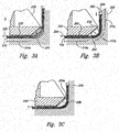
- the expandable member 236 can be deflated as shown in Figure 3C .
- the tooling aid 230 can then be removed from the tool 202. If the fiber material 210 includes resin at this stage, then the lay-up is ready for curing. Alternatively, if the fiber material 210 was applied dry, then resin can be infused with the fibers using a suitable resin infusion process, such as that described in co-pending U.S. Patent Application Serial No. 10/485,725, filed May 28, 2003 . After resin infusion, the lay-up can be cured using an autoclave, oven, or other suitable curing process.
- Tooling aid 230 in the manner described above with reference to Figures 2-3C can prevent the fiber material 210 from bridging across the interior transition regions 206 of the tool 202.
- One advantage of this feature is that the resulting composite part may not have reduced fiber density, and hence reduced structural properties, in corresponding transition regions.
- Another advantage is that a single female tool can be used to manufacture a wide range of parts (e.g., frames) having the same external dimensions but different thicknesses, without compromising part quality or structural integrity.
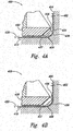
- Figures 4A and 4B are cross-sectional end views of a portion of a tooling system 400 that utilizes a contoured former 437 in accordance with another embodiment of the invention.
- the tooling system 400 includes a female tool 402 ("tool 402") and a tooling aid 430 that are at least generally similar in structure and function to the female tool 202 and the tooling aid 230, respectively, described above with reference to Figures 2-3C .
- the tooling aid 430 includes a pressing device 434 having an expandable member 436 that is at least generally similar in structure and function to the expandable member 236 described above with reference to Figures 2-3C .
- a fiber material 410 is positioned on a mold surface 404 of the tool 402, and a sealing layer 420 is positioned over the fiber material 410.
- the contoured former 437 is positioned against the sealing layer 420 in a transition region 406 of the mold surface 404.
- the contoured former 437 can include an outer forming surface 439 that at least approximates the shape of the transition region 406.
- the expandable member 436 As shown in Figure 4B , as the expandable member 436 is inflated, it drives the contoured former 437 into the transition region 406, thereby compressing a portion of the fiber material 410 into the transition region 406. While the expandable member 436 is inflated, the sealing layer 420 is evacuated to hold the fiber material 410 in position against the mold surface 404. After evacuating the sealing layer 420, the inflatable device 436 is deflated and the tooling aid 430 and the contoured former 437 can be removed from the tool 402 for curing of the lay-up as described above with reference to Figures 3A-3C .
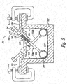
- FIG. 5 is a cross-sectional end view of a composite tooling system 500 that includes a tooling aid 530 configured to cooperate with a female tool 502 ("tool 502").
- the tool 502 includes a mold surface 504 having a first transition region 506a spaced apart from a second transition region 506b.
- the tooling aid 530 includes mechanical pressing devices 534 (identified individually as a first pressing device 534a and a second pressing device 534b) configured in accordance with another embodiment of the invention.
- Each of the mechanical pressing devices 534 includes at least one driving member 546 rotatably coupled to a contoured former 537.
- the contoured formers 537 can include rigid or semi-rigid tubular segments having cross-sectional radii that approximate the curvature of the corresponding transition regions 506 of the mold surface 504.
- each of the driving members 546 includes a threaded portion 542 threadably engaging a corresponding threaded bore 533 extending through a base portion 531 of the tooling aid 530.
- the base portion 531 can be temporarily fixed to the tool 502 by clamps or other suitable devices.
- Each of the driving members 546 further includes a head portion 541 configured to be turned by a wrench or other torquing device.
- Rotation of the driving members 546 in a first direction 561 moves the corresponding contoured formers 537 toward the adjacent transition regions 506.
- the pressing devices 534 can be used to compress a fiber material 510 into the transition regions 506 while the space under a sealing layer 520 is at least partially evacuated as described above with reference to Figures 2-3C .
- the driving members 546 can be rotated in a second direction 562 to move the corresponding contoured formers 537 away from the adjacent transition regions 506 to facilitate removal of the tooling aid 530 from the tool 502 for subsequent operations.
- the fiber material 510 was pre-impregnated with resin, such operations can include resin curing.
- the fiber material 510 was applied dry, such operations can include resin infusion followed by curing.
- Figure 6 is a side elevation view of two of the tooling aids 530 (identified individually as a first tooling aid 530a and a second tooling aid 530b) positioned end-to-end for the purpose of illustrating an interlocking feature 660 configured in accordance with an embodiment of the invention.
- Such an arrangement may be necessary and/or advantageous when manufacturing composite parts with a relatively long and/or curved female tool (not shown).
- multiple tooling aids 530 can be arranged in end-to-end fashion as required to accommodate the length and/or curvature of the particular tool.
- an interlocking feature such as the interlocking feature 660, can be utilized to provide continuous pressure along the corresponding interior transition region of the tool.
- the interlocking feature 660 includes a male portion 662 extending from the first contoured former 537a, and a corresponding female portion 664 extending from the adjacent second contoured former 537b.
- the female portion 664 is configured to receive the male portion 662 in an overlapping manner to provide an at least approximately continuous contoured former 637.
- the interlocking tooling aids 530 can provide at least approximately continuous pressure over long and/or curved transition regions of a female tool.
- Figure 7 is an isometric view of a composite tooling system 700 that includes a plurality of tooling aids 730 (identified individually as tooling aids 730a-730 i ) positioned end-to-end in a female tool 702 in accordance with an embodiment of the invention.
- the tooling aids 730 can be at least generally similar in structure and function to the tooling aids 530 described above with reference to Figures 5 and 6 .
- tooling aids that are at least generally similar to the tooling aids 230 and 430 described above with reference to Figures 2-4 can be used with the tool 702 in a manner similar to that illustrated in Figure 7 .
Landscapes
- Engineering & Computer Science (AREA)
- Chemical & Material Sciences (AREA)
- Composite Materials (AREA)
- Mechanical Engineering (AREA)
- Textile Engineering (AREA)
- Moulding By Coating Moulds (AREA)
- Casting Or Compression Moulding Of Plastics Or The Like (AREA)
Abstract
positioning a plurality of fibers on a mold surface (204) of a tool (202);
covering the fibers with a sealing layer (220);
pressing a portion of the covered fibers against an interior transition region (206a, 206b) of the mold surface with a pressing device (234a, 234b); and
while pressing the portion of covered fibers against the interior transition region, removing air from between the sealing layer and the mold surface to draw at least a partial vacuum between the sealing layer and the mold surface.
means for positioning a plurality of fibers in the shape of the fiber-reinforced resin part;
means for covering the plurality of fibers with a sealing layer;
means, separate from the means for covering, for pressing a portion of the plurality of fibers against an interior transition region of the means for positioning; and
means for drawing at least a partial vacuum between the means for covering and the means for positioning while pressing the portion of fibers against the interior transition region.
Description
- The following disclosure relates generally to composite part manufacturing and, more particularly, to tooling aids for manufacturing composite parts with female tools.
- Fiber-reinforced resin materials, or "composite" materials as they are commonly known, have many applications in the aerospace, automotive, and marine fields because of their high strength-to-weight ratios, corrosion resistance, and other unique properties. Conventional composite materials typically include glass, carbon, or polyaramide fibers in woven and/or non-woven configurations. The fibers can be pre-impregnated with uncured resin to form fiber plies in a raw material stage. The fiber plies can be manufactured into parts by laminating them on a mold surface. Heat and pressure can be applied to the laminated plies to cure the resin and harden the laminate in the shape of the mold. The heat and pressure can be applied with an autoclave, a heated flat or contoured forming tool, or a combination of methods including the use of a vacuum bag.
- Composite parts can be formed in the above manner on both male and female tools. With male tools, the fiber plies are applied to an exterior mold surface that forms an inner mold line of the part. Adding plies to the lay-up on a male tool increases the thickness of the part and changes the outer mold line, but the inner mold line remains unchanged. Conversely, with female tools, the fiber plies are applied to an interior mold surface that forms an outer mold line of the part. Adding plies to the lay-up on a female tool increases the thickness of the part and changes the inner mold line, but the outer mold line remains unchanged.
- Female tools are desirable when the mating surface is located on the exterior of a part because female tools allow the outer mold line (i.e., the exterior surface) to be tightly controlled. Female tooling (also known as outer mold line tooling) is also desirable when making multiple parts having the same external dimensions but different thicknesses. Aircraft, for example, often include multiple fuselage frames having the same external dimensions but different thicknesses. In this situation, a single female tool can be used to make all of the frames, regardless of thickness, because the female tool allows the thickness to vary without changing the external dimensions. If future growth of the aircraft requires further thickening of the frames, this can be achieved without changing tooling. Conversely, if male tooling were used, then a separate tool would be required for each different frame thickness.
- One problem that arises when manufacturing composite parts with female tooling is that the fiber plies tend to bridge across internal radii on the mold surface.
Figure 1 , for example, illustrates a cross-sectional end view offiber material 110 laid up on a portion of afemale tool 102 in accordance with the prior art. Thefemale tool 102 includes aninterior mold surface 104 having afirst side region 103 spaced apart from asecond side region 105 by aradius region 106. Avacuum bag 120 is positioned over thefiber material 110. As thevacuum bag 120 is evacuated, the outside air pressure presses thefiber material 110 firmly against theside regions fiber material 110 into theradius region 106. This resistance causes thefiber material 110 to bridge across theradius region 106, reducing the fiber density in this region. The reduced fiber density can compromise the structural integrity of the finished part. - The present invention is directed generally toward methods and systems for manufacturing composite parts with female tools. A method for manufacturing a composite part in accordance with one aspect of the invention includes positioning a plurality of fibers on a mold surface of a tool, and covering the fibers with a sealing layer. The method can further include pressing a portion of the covered fibers against an interior transition region of the mold surface with a pressing device. While the portion of covered fibers is being pressed against the interior transition region, air can be removed from between the sealing layer and the mold surface to draw at least a partial vacuum between the sealing layer and the mold surface. In one embodiment, the portion of covered fibers can be pressed against the interior transition region of the mold surface by a pneumatic pressing device. In another embodiment, the portion of covered fibers can be pressed against the interior transition region by a mechanical pressing device.
- A tooling system for manufacturing a composite part in accordance with another aspect of the invention includes a tool and a tooling aid configured to cooperate with the tool. The tool can have a mold surface with a first side region, a second side region, and an interior transition region positioned between the first and second side regions. The tooling aid can include an outwardly movable pressing device configured to compress a portion of fibers against the interior transition region of the mold surface when manufacturing a composite part with the tool. In one embodiment, the pressing device can include an inflatable member. In another embodiment, the pressing device can include a mechanical driver.
-
-
Figure 1 is a cross-sectional end view of fiber material laid up on a female tool in accordance with the prior art. -
Figure 2 is a partially exploded, cross-sectional end view of a composite tooling system configured in accordance with an embodiment of the invention. -
Figures 3A-3C are enlarged, cross-sectional end views of a portion of the tooling system ofFigure 2 , illustrating operation of a tooling aid configured in accordance with an embodiment of the invention. -
Figure 4A and 4B are cross-sectional end views of a composite tooling system that includes a contoured former configured in accordance with another embodiment of the invention. -
Figure 5 is a cross-sectional end view of a composite tooling system that includes a mechanical pressing device configured in accordance with a further embodiment of the invention. -
Figure 6 is a side elevation view of two tooling aids for the purpose of illustrating an interlocking feature configured in accordance with an embodiment of the invention. -
Figure 7 is an isometric view of a composite tooling system having a plurality of tooling aid segments arranged in end-to-end fashion in accordance with an embodiment of the invention. - The following disclosure describes methods and systems for manufacturing composite parts. Certain details are set forth in the following description and in
Figures 2-7 to provide a thorough understanding of various embodiments of the invention. Other details describing well-known structures and systems often associated with composite parts and composite part manufacturing are not set forth in the following disclosure to avoid unnecessarily obscuring the description of the various embodiments of the invention. - Many of the details, dimensions, angles, and other features shown in the Figures are merely illustrative of particular embodiments of the invention. Accordingly, other embodiments can have other details, dimensions, angles, and features without departing from the spirit or scope of the present invention. In addition, further embodiments can be practiced without several of the details described below.
- In the Figures, identical reference numbers identify identical or at least generally similar elements. To facilitate the discussion of any particular element, the most significant digit or digits of any reference number refer to the Figure in which that element is first introduced. For example,
element 230 is first introduced and discussed with reference toFigure 2 . -
Figure 2 is a partially exploded, cross-sectional end view of acomposite tooling system 200 configured in accordance with an embodiment of the invention. In one aspect of this embodiment, thetooling system 200 includes atooling aid 230 configured to cooperate with a female tool 202 ("tool 202"). Thetool 202 can include aninterior mold surface 204 forming a U-shaped channel having afirst side region 203 spaced apart from asecond side region 205 by a first transition region 206a, and athird side region 207 spaced apart from thesecond side region 205 by a second transition region 206b. In the illustrated embodiment, thetransition regions 206 include surfaces defining internal radii. In other embodiments, however, thetransition regions 206 can have other shapes without departing from the spirit or scope of the present invention. Such shapes can include, for example, beveled surfaces and curved surfaces with elliptical, oval, and other curved components. - To manufacture a composite part with the
tool 202, afiber material 210 is positioned against themold surface 204. A sealing layer 220 (e.g., a vacuum bag) can be positioned over thefiber material 210 for subsequent evacuation of the space between thesealing layer 220 and themold surface 204. In one embodiment, thefiber material 210 can include a plurality of woven and/or non-woven fibers preimpregnated with resin. In another embodiment, thefiber material 210 can be applied to themold surface 204 dry and infused with resin during or after the evacuation process. One method for infusing a dry fiber lay up with resin is described in detail in co-pendingU.S. Application Serial No. 10/485,725 PCT/US03/16794 , and incorporated herein in its entirety by reference. - The
tooling aid 230 can include asupport portion 232 extending downwardly from abase portion 231. Thebase portion 231 can be held against thetool 202 by an arrangement of clampingdevices 242 to position thesupport portion 232 in thetool 202. As described in greater detail below, when thesupport portion 232 is fully positioned intool 202, a holding device 238 (e.g., a pad) positioned on a distal end of thesupport portion 232 presses against thesealing layer 220 and traps a portion of thefiber material 210 against thesecond side region 205 of themold surface 204. The holdingdevice 238 can include a compressible material such as rubber, or other materials such as Teflon, plastic, etc. that can hold thefiber material 210 in position against the tool surface without damaging thesealing layer 220. - The
tooling aid 230 further includes a first pressing device 234a and a second pressing device 234b positioned toward the distal end of thesupport portion 232. The pressing devices 234 are positioned to face outwardly toward the correspondingtransition regions 206 of thetool 202 when thesupport portion 232 is fully positioned in thetool 202. Each of the pressing devices 234 of the illustrated embodiment includes an expandable member 236 (e.g., an inflatable bladder, tube, etc.) that expands outwardly against thecorresponding transition region 206 when inflated, as described in more detail below with reference toFigures 3A-3C . In one embodiment, theexpandable members 236 can include flexible and/or elastic materials such as rubber, fiber-reinforced rubber, plastic, nylon, etc. In other embodiments, theexpandable members 236 can include other suitably flexible and/or expandable materials. Theexpandable members 236 can be at least partially attached to thesupport portion 232 by an adhesive or other means to facilitate positioning in thetool 202. In other embodiments, however, theexpandable members 236 do not have to be attached to thesupport portion 232, and can instead be manually positioned between thesupport portion 232 and thecorresponding transition regions 206 for use. -
Figures 3A-3C are enlarged, cross-sectional end views of a portion of thetooling system 200 ofFigure 2 , illustrating operation of thetooling aid 230 in accordance with an embodiment of the invention. Referring first toFigure 3A , operation begins by clamping thetooling aid 230 into position in thetool 202 using for example, the clampingdevices 242 ofFigure 2 . In this position, the holdingdevice 238 contacts thesealing layer 220 and compresses afirst portion 310a of thefiber material 210 against thesecond side region 205. - Referring next to
Figure 3B , while thefirst portion 310a of thefiber material 210 is held against thesecond side region 205, theexpandable member 236 is inflated to compress an adjacent second portion 310b of thefiber material 210 into thetransition region 206. As the second portion 310b offiber material 210 is compressed into thetransition region 206, athird portion 310c of thefiber material 210 moves downwardly along thefirst side region 203 as needed to accommodate movement of the second portion 310b. While theexpandable member 236 is fully inflated, at least a partial vacuum is drawn between thesealing layer 220 and themold surface 204. The resulting air pressure caused by the vacuum holds thefiber material 210 firmly in place against thetransition region 206 and the other portions of themold surface 204. - After the
sealing layer 220 has been sufficiently evacuated, theexpandable member 236 can be deflated as shown inFigure 3C . Thetooling aid 230 can then be removed from thetool 202. If thefiber material 210 includes resin at this stage, then the lay-up is ready for curing. Alternatively, if thefiber material 210 was applied dry, then resin can be infused with the fibers using a suitable resin infusion process, such as that described in co-pendingU.S. Patent Application Serial No. 10/485,725, filed May 28, 2003 - Use of the
tooling aid 230 in the manner described above with reference toFigures 2-3C can prevent thefiber material 210 from bridging across theinterior transition regions 206 of thetool 202. One advantage of this feature is that the resulting composite part may not have reduced fiber density, and hence reduced structural properties, in corresponding transition regions. Another advantage is that a single female tool can be used to manufacture a wide range of parts (e.g., frames) having the same external dimensions but different thicknesses, without compromising part quality or structural integrity. -
Figures 4A and 4B are cross-sectional end views of a portion of atooling system 400 that utilizes a contoured former 437 in accordance with another embodiment of the invention. Referring first toFigure 4A , thetooling system 400 includes a female tool 402 ("tool 402") and atooling aid 430 that are at least generally similar in structure and function to thefemale tool 202 and thetooling aid 230, respectively, described above with reference toFigures 2-3C . Accordingly, thetooling aid 430 includes apressing device 434 having anexpandable member 436 that is at least generally similar in structure and function to theexpandable member 236 described above with reference toFigures 2-3C . - In the illustrated embodiment, a
fiber material 410 is positioned on amold surface 404 of thetool 402, and asealing layer 420 is positioned over thefiber material 410. The contoured former 437 is positioned against thesealing layer 420 in atransition region 406 of themold surface 404. The contoured former 437 can include an outer formingsurface 439 that at least approximates the shape of thetransition region 406. - As shown in
Figure 4B , as theexpandable member 436 is inflated, it drives the contoured former 437 into thetransition region 406, thereby compressing a portion of thefiber material 410 into thetransition region 406. While theexpandable member 436 is inflated, thesealing layer 420 is evacuated to hold thefiber material 410 in position against themold surface 404. After evacuating thesealing layer 420, theinflatable device 436 is deflated and thetooling aid 430 and the contoured former 437 can be removed from thetool 402 for curing of the lay-up as described above with reference toFigures 3A-3C . - Although the
pressing devices 234 and 434 described above with reference toFigures 2-4B include expandable (e.g., inflatable) members, in other embodiments, other types of pressing devices can be used to compress and/or compact fiber material into interior transition regions in accordance with the present invention.Figure 5 , for example, is a cross-sectional end view of acomposite tooling system 500 that includes a tooling aid 530 configured to cooperate with a female tool 502 ("tool 502"). Thetool 502 includes amold surface 504 having a first transition region 506a spaced apart from a second transition region 506b. The tooling aid 530 includes mechanical pressing devices 534 (identified individually as a first pressing device 534a and a secondpressing device 534b) configured in accordance with another embodiment of the invention. - Each of the mechanical pressing devices 534 includes at least one driving
member 546 rotatably coupled to a contoured former 537. The contoured formers 537 can include rigid or semi-rigid tubular segments having cross-sectional radii that approximate the curvature of thecorresponding transition regions 506 of themold surface 504. In the illustrated embodiment, each of the drivingmembers 546 includes a threadedportion 542 threadably engaging a corresponding threaded bore 533 extending through abase portion 531 of the tooling aid 530. Thebase portion 531 can be temporarily fixed to thetool 502 by clamps or other suitable devices. Each of the drivingmembers 546 further includes ahead portion 541 configured to be turned by a wrench or other torquing device. - Rotation of the driving
members 546 in afirst direction 561 moves the corresponding contoured formers 537 toward theadjacent transition regions 506. In this manner, the pressing devices 534 can be used to compress afiber material 510 into thetransition regions 506 while the space under a sealing layer 520 is at least partially evacuated as described above with reference toFigures 2-3C . Once a vacuum or partial vacuum has been drawn, the drivingmembers 546 can be rotated in asecond direction 562 to move the corresponding contoured formers 537 away from theadjacent transition regions 506 to facilitate removal of the tooling aid 530 from thetool 502 for subsequent operations. If thefiber material 510 was pre-impregnated with resin, such operations can include resin curing. Alternatively, if thefiber material 510 was applied dry, such operations can include resin infusion followed by curing. -
Figure 6 is a side elevation view of two of the tooling aids 530 (identified individually as afirst tooling aid 530a and a second tooling aid 530b) positioned end-to-end for the purpose of illustrating aninterlocking feature 660 configured in accordance with an embodiment of the invention. Such an arrangement may be necessary and/or advantageous when manufacturing composite parts with a relatively long and/or curved female tool (not shown). For such parts, multiple tooling aids 530 can be arranged in end-to-end fashion as required to accommodate the length and/or curvature of the particular tool. To avoid localized fiber bridging between the adjacent contoured formers 537 (identified individually as a first contoured former 537a and a second contoured former 537b for ease of reference), an interlocking feature, such as the interlockingfeature 660, can be utilized to provide continuous pressure along the corresponding interior transition region of the tool. - In the illustrated embodiment, the interlocking
feature 660 includes amale portion 662 extending from the first contoured former 537a, and a correspondingfemale portion 664 extending from the adjacent second contoured former 537b. Thefemale portion 664 is configured to receive themale portion 662 in an overlapping manner to provide an at least approximately continuous contoured former 637. In this way, the interlocking tooling aids 530 can provide at least approximately continuous pressure over long and/or curved transition regions of a female tool. -
Figure 7 is an isometric view of acomposite tooling system 700 that includes a plurality of tooling aids 730 (identified individually as tooling aids 730a-730i) positioned end-to-end in afemale tool 702 in accordance with an embodiment of the invention. In one aspect of this embodiment, the tooling aids 730 can be at least generally similar in structure and function to the tooling aids 530 described above with reference toFigures 5 and6 . In other embodiments, however, tooling aids that are at least generally similar to the tooling aids 230 and 430 described above with reference toFigures 2-4 can be used with thetool 702 in a manner similar to that illustrated inFigure 7 . - In another aspect of this embodiment, the
tool 702 is curved and relatively long. Such a tool can be used, for example, to manufacture composite frame sections for aircraft fuselages and/or other structures. When manufacturing such parts with thetooling system 700, pressure from the tooling aids 730 can be applied to the composite material (not shown) in at least one of two ways. The first method involves applying pressure with thetooling aid 730e near a mid-portion 773 of thetool 702 first, and then working outwardly from there toward afirst end 771 and an oppositesecond end 772. The second method involves applying pressure with the tooling aid 730a near thefirst end 771 of thetool 702 first, and then working from there toward thesecond end 772. Applying pressure to the composite material using one of these two methods can avoid material bunching and/or wrinkles in the finished part. For composite parts having ply-ramps or joggles, the contoured formers 537 (Figures 5 and6 ) can include corresponding ramps or joggles to match the tool surface dimensions on either side of the features to avoid bridging fibers in the composite material over these features. - From the foregoing, it will be appreciated that specific embodiments of the invention have been described herein for purposes of illustration, but that various modifications may be made without deviating from the spirit and scope of the invention. For example, aspects described in the context of particular embodiments can be combined or eliminated in other embodiments. Accordingly, the invention is not limited, except as by the appended claims.
Claims (15)
- A method for manufacturing a fiber-reinforced resin part, the method comprising:
positioning a plurality of fibers on a mold surface of a tool; covering the fibers with a sealing layer; pressing a portion of the covered fibers against an interior transition region of the mold surface with a pressing device; and while pressing the portion of covered fibers against the interior transition region, removing air from between the sealing layer and the mold surface to draw at least a partial vacuum between the sealing layer and the mold surface. - The method of claim 1 wherein pressing a portion of the covered fibers against an interior transition region includes compressing the portion of covered fibers between a pneumatic or mechanical pressing device and the interior transition region.
- The method of claim 1 or 2 wherein pressing a portion of the covered fibers against an interior transition region includes inflating an expandable member against the sealing layer to compress the portion of covered fibers between the expandable member and the interior transition region.
- The method of any one of the preceding claims wherein pressing a portion of the covered fibers against an interior transition region includes pressing a first portion of the covered fibers, and wherein the method further comprises pressing a second portion of the covered fibers against a side region of the mold surface adjacent to the interior transition region while removing the air from between the sealing layer and the mold surface.
- The method of any one of the preceding claims, further comprising flowing resin between the sealing layer and the mold surface to infuse the plurality of fibers with resin.
- The method of any one of the preceding claims wherein positioning a plurality of fibers on a mold surface of a tool includes positioning a plurality of fibers on a female mold surface, the female mold surface including the interior transition region positioned between a first side region and a second side region.
- The method of any one of claims 3-6, further comprising positioning a contoured former proximate to the interior transition region of the mold surface after covering the fibers with the sealing layer, wherein inflating an expandable member against the sealing layer to compress a portion of the fibers includes inflating the expandable member against the contoured former to compress the portion of fibers between the contoured former and the interior transition region of the mold surface.
- The method of claim 6 or 7, further comprising positioning a tooling aid at least proximate to the mold surface of the female tool, wherein inflating an expandable member against the sealing layer includes inflating an expandable member supported by the tooling aid.
- The method of any one of the preceding claims, further comprising mechanically driving a former against the sealing layer to compress a portion of the fibers between the former and the interior transition region of the mold surface.
- The method of claim 9 wherein mechanically driving a former against the sealing layer includes rotating a threaded member operably coupled to the former to move the former toward the transition region of the mold surface.
- A system for manufacturing a fiber-reinforced resin part, the system comprising:means for positioning a plurality of fibers in the shape of the fiber-reinforced resin part;means for covering the plurality of fibers with a sealing layer;means, separate from the means for covering, for pressing a portion of the plurality of fibers against an interior transition region of the means for positioning; andmeans for drawing at least a partial vacuum between the means for covering and the means for positioning while pressing the portion of fibers against the interior transition region.
- The system of claim 11 wherein the interior transition region of the means for positioning is positioned between first and second side regions of the means for positioning.
- The system of claim 11 or 12 wherein the means for pressing a portion of the fibers against an interior transition region include means for inflating an expandable member against the portion of fibers.
- The system of any one of claims 11-13 wherein the means for pressing a portion of the fibers against an interior transition region include means for driving a mechanical member against the portion of fibers.
- The system of any one of claims 11-14, further comprising means for flowing resin between the means for covering and the means for positioning to infuse the plurality of fibers with resin.
Applications Claiming Priority (3)
| Application Number | Priority Date | Filing Date | Title |
|---|---|---|---|
| US10/899,660 US7622066B2 (en) | 2004-07-26 | 2004-07-26 | Methods and systems for manufacturing composite parts with female tools |
| EP05775171.1A EP1778460B1 (en) | 2004-07-26 | 2005-07-25 | Methods and systems for manufacturing composite parts with female tools |
| PCT/US2005/026141 WO2006014825A1 (en) | 2004-07-26 | 2005-07-25 | Methods and systems for manufacturing composite parts with female tools |
Related Parent Applications (3)
| Application Number | Title | Priority Date | Filing Date |
|---|---|---|---|
| EP05775171.1A Division EP1778460B1 (en) | 2004-07-26 | 2005-07-25 | Methods and systems for manufacturing composite parts with female tools |
| EP05775171.1A Division-Into EP1778460B1 (en) | 2004-07-26 | 2005-07-25 | Methods and systems for manufacturing composite parts with female tools |
| USPCT/US5026/141 Previously-Filed-Application | 2005-07-25 |
Publications (2)
| Publication Number | Publication Date |
|---|---|
| EP3398758A1 true EP3398758A1 (en) | 2018-11-07 |
| EP3398758B1 EP3398758B1 (en) | 2022-04-13 |
Family
ID=35656304
Family Applications (2)
| Application Number | Title | Priority Date | Filing Date |
|---|---|---|---|
| EP05775171.1A Expired - Lifetime EP1778460B1 (en) | 2004-07-26 | 2005-07-25 | Methods and systems for manufacturing composite parts with female tools |
| EP17202830.0A Expired - Lifetime EP3398758B1 (en) | 2004-07-26 | 2005-07-25 | Method and system for manufacturing composite parts with female tools |
Family Applications Before (1)
| Application Number | Title | Priority Date | Filing Date |
|---|---|---|---|
| EP05775171.1A Expired - Lifetime EP1778460B1 (en) | 2004-07-26 | 2005-07-25 | Methods and systems for manufacturing composite parts with female tools |
Country Status (5)
| Country | Link |
|---|---|
| US (2) | US7622066B2 (en) |
| EP (2) | EP1778460B1 (en) |
| ES (1) | ES2664245T3 (en) |
| PT (1) | PT1778460T (en) |
| WO (1) | WO2006014825A1 (en) |
Cited By (1)
| Publication number | Priority date | Publication date | Assignee | Title |
|---|---|---|---|---|
| CN113246500A (en) * | 2021-06-30 | 2021-08-13 | 成都飞机工业(集团)有限责任公司 | Preparation device of composite material cap part with stop block and operation method of preparation device |
Families Citing this family (66)
| Publication number | Priority date | Publication date | Assignee | Title |
|---|---|---|---|---|
| US9586699B1 (en) | 1999-08-16 | 2017-03-07 | Smart Drilling And Completion, Inc. | Methods and apparatus for monitoring and fixing holes in composite aircraft |
| US9625361B1 (en) | 2001-08-19 | 2017-04-18 | Smart Drilling And Completion, Inc. | Methods and apparatus to prevent failures of fiber-reinforced composite materials under compressive stresses caused by fluids and gases invading microfractures in the materials |
| US7622066B2 (en) * | 2004-07-26 | 2009-11-24 | The Boeing Company | Methods and systems for manufacturing composite parts with female tools |
| US7306450B2 (en) * | 2004-09-29 | 2007-12-11 | The Boeing Company | Apparatuses, systems, and methods for manufacturing composite parts |
| US8557165B2 (en) * | 2008-10-25 | 2013-10-15 | The Boeing Company | Forming highly contoured composite parts |
| US8601694B2 (en) | 2008-06-13 | 2013-12-10 | The Boeing Company | Method for forming and installing stringers |
| EP1775109B1 (en) * | 2005-10-17 | 2011-03-09 | Saab Ab | Composite moulding method and apparatus with a vacuum bag |
| US7824171B2 (en) * | 2005-10-31 | 2010-11-02 | The Boeing Company | Corner-consolidating inflatable apparatus and method for manufacturing composite structures |
| US7655168B2 (en) | 2006-01-31 | 2010-02-02 | The Boeing Company | Tools for manufacturing composite parts and methods for using such tools |
| GB0613872D0 (en) | 2006-07-12 | 2006-08-23 | Airbus Uk Ltd | Method of manufacturing composite part |
| US7849729B2 (en) | 2006-12-22 | 2010-12-14 | The Boeing Company | Leak detection in vacuum bags |
| GB0703110D0 (en) * | 2007-02-16 | 2007-03-28 | Vnf Designs Europ Ltd | Manufacture of carbon-fibre reinforced polymer structures |
| US8388795B2 (en) | 2007-05-17 | 2013-03-05 | The Boeing Company | Nanotube-enhanced interlayers for composite structures |
| US9770871B2 (en) | 2007-05-22 | 2017-09-26 | The Boeing Company | Method and apparatus for layup placement |
| US8568551B2 (en) | 2007-05-22 | 2013-10-29 | The Boeing Company | Pre-patterned layup kit and method of manufacture |
| ITMI20071308A1 (en) * | 2007-06-29 | 2008-12-30 | Mako Shark Srl | EQUIPMENT FOR CONSTRUCTION IN PRESS OF PARTS IN COMPOSITE MATERIAL |
| US8707766B2 (en) | 2010-04-21 | 2014-04-29 | The Boeing Company | Leak detection in vacuum bags |
| US8333864B2 (en) | 2008-09-30 | 2012-12-18 | The Boeing Company | Compaction of prepreg plies on composite laminate structures |
| US8936695B2 (en) | 2007-07-28 | 2015-01-20 | The Boeing Company | Method for forming and applying composite layups having complex geometries |
| US8042767B2 (en) | 2007-09-04 | 2011-10-25 | The Boeing Company | Composite fabric with rigid member structure |
| GB0719267D0 (en) * | 2007-10-04 | 2007-11-14 | Airbus Uk Ltd | Method of monitoring the performance of a pressure intensifier |
| US8916010B2 (en) | 2007-12-07 | 2014-12-23 | The Boeing Company | Composite manufacturing method |
| US8752293B2 (en) | 2007-12-07 | 2014-06-17 | The Boeing Company | Method of fabricating structures using composite modules and structures made thereby |
| DE102008017381B4 (en) * | 2008-04-05 | 2011-12-08 | Deutsches Zentrum für Luft- und Raumfahrt e.V. | Method and aid for the production of components made of fiber composite material |
| WO2009132229A2 (en) * | 2008-04-24 | 2009-10-29 | Medtronic, Inc. | Cold ionizing radiation sterilization |
| US8465613B2 (en) | 2011-08-24 | 2013-06-18 | The Boeing Company | Method and apparatus for fabricating variable gauge, contoured composite stiffeners |
| US9254619B2 (en) | 2008-05-28 | 2016-02-09 | The Boeing Company | Method and apparatus for fabricating variable gauge, contoured composite stiffeners |
| FR2936442B1 (en) * | 2008-09-30 | 2013-03-08 | Airbus France | DEVICE FOR MANUFACTURING A COMPOUND COMPOSITE MATERIAL PART. |
| KR101033476B1 (en) * | 2009-01-08 | 2011-05-09 | 주식회사 대한항공 | Prepreg bending machine and its molding method |
| DK2308670T3 (en) * | 2009-10-12 | 2014-02-10 | Vestas Wind Sys As | A method of producing a wind turbine blade in a mold comprising a fixing device |
| US9604417B2 (en) | 2011-04-05 | 2017-03-28 | The Boeing Company | Method for making contoured composite stiffeners |
| US9776385B2 (en) * | 2011-04-05 | 2017-10-03 | Sikorsky Aircraft Corporation | External to bagging mechanical clamp |
| US8771575B2 (en) * | 2011-07-27 | 2014-07-08 | Dieffenbacher GmbH Maschinen- und Anlagenbau | Methods and systems for forming reinforced composite articles having variable thickness corners |
| US9387628B2 (en) | 2011-08-24 | 2016-07-12 | The Boeing Company | Method and apparatus for fabricating composite stringers |
| FR2985927B1 (en) * | 2012-01-25 | 2014-12-26 | Snecma | TOOLS FOR MAKING A PROPELLER BLADE, COMPRISING A CLAMPING SKATE |
| US9457435B2 (en) | 2012-01-25 | 2016-10-04 | Snecma | Method for producing a propeller blade from a composite material |
| FR2995244B1 (en) * | 2012-09-07 | 2014-10-10 | Airbus Operations Sas | METHOD FOR MAKING A COMPOSITE MATERIAL PROFILE HAVING A RETRACTING ANGLE FROM A STACK OF FIBER LAYERS |
| US9162396B2 (en) * | 2012-10-12 | 2015-10-20 | The Boeing Company | Method for forming fuselage stringers |
| JP6073499B2 (en) * | 2012-12-28 | 2017-02-01 | コンポジテンス ゲーエムベーハーCompositence GmbH | Method and apparatus for manufacturing a three-dimensional fiber fabric and a structural part preform made of fiber in two steps |
| US9511519B2 (en) | 2014-02-04 | 2016-12-06 | The Boeing Company | System and method of vacuum bagging composite parts |
| GB201413637D0 (en) * | 2014-07-31 | 2014-09-17 | Mclaren Applied Technologies Ltd | Manufacture of vehicle structures |
| US9636876B2 (en) * | 2014-10-29 | 2017-05-02 | The Boeing Company | Method, device and apparatus for vacuum forming composite laminates |
| US10081140B2 (en) * | 2014-10-29 | 2018-09-25 | The Boeing Company | Apparatus for and method of compaction of a prepreg |
| EP3042747B1 (en) * | 2015-01-12 | 2018-03-14 | Airbus Operations GmbH | Forming apparatus and method for forming a semi-finished product comprising reinforcement fibres |
| US9974360B2 (en) | 2015-04-08 | 2018-05-22 | Nike, Inc. | Method of manufacturing a bladder element with an etched feature and article having a bladder element with an etched feature |
| WO2016164549A1 (en) | 2015-04-08 | 2016-10-13 | Nike Innovate C.V. | Article including a bladder element with an image and method of manufacturing the article |
| EP3590376B1 (en) | 2015-04-08 | 2022-02-02 | Nike Innovate C.V. | Article having bladder element with impression |
| WO2016164550A1 (en) | 2015-04-08 | 2016-10-13 | Nike Innovate C.V. | Article with overlay secured to bladder element over image and method of manufacturing the article |
| US9669589B2 (en) * | 2015-06-08 | 2017-06-06 | Siemens Aktiengesellschaft | Hybrid solid-inflatable mandrel for blade manufacturing |
| US10369740B2 (en) | 2015-07-09 | 2019-08-06 | The Boeing Company | Method of forming a contoured hat stiffener |
| US10213461B2 (en) * | 2015-08-24 | 2019-02-26 | Arthrex, Inc | Combined autologous biologic and cold therapy treatment of skin injuries |
| US10661513B2 (en) | 2015-12-01 | 2020-05-26 | The Boeing Company | Multi-planar fiber matrix tool-less preform for resin infusion |
| GB2556043A (en) * | 2016-11-11 | 2018-05-23 | Composite Tech And Applications Limited | A method of de-bulking a pre-form for a composite component |
| US10502074B2 (en) * | 2017-04-07 | 2019-12-10 | General Electric Company | Methods and assemblies for forming features in composite components |
| GB2566433A (en) * | 2017-07-13 | 2019-03-20 | Spirit Aerosystems Europe Ltd | Composite lay-up apparatus and method |
| US10710319B2 (en) | 2017-08-02 | 2020-07-14 | The Boeing Company | Controlling application of forces to different portions of object surface using bladder |
| US10710320B2 (en) | 2017-08-02 | 2020-07-14 | The Boeing Company | Controlling application of forces to different portions of object surface using flexible wall |
| JP6901575B2 (en) | 2017-09-06 | 2021-07-14 | 株式会社Subaru | Preform shaper |
| US11559954B2 (en) | 2020-01-16 | 2023-01-24 | The Boeing Company | Multi-chamber conformable bladder for composite part tooling |
| US11993031B2 (en) * | 2021-06-18 | 2024-05-28 | Goodrich Corporation | Carbonization shape forming of oxidized PAN fiber preform |
| US20220402827A1 (en) * | 2021-06-18 | 2022-12-22 | Goodrich Corporation | Wedge and plug tooling for pre-carbonization compression of oxidized pan fiber preform |
| US20220402828A1 (en) * | 2021-06-18 | 2022-12-22 | Goodrich Corporation | Shape forming opf preform |
| US12138864B2 (en) * | 2021-08-30 | 2024-11-12 | The Boeing Company | Forming apparatus, methods, and systems |
| EP4183561A1 (en) | 2021-11-23 | 2023-05-24 | Fundació Eurecat | Vacuum infusion system and method for vacuum infusing a fibre reinforcement with a resin |
| US12508747B2 (en) | 2022-10-31 | 2025-12-30 | Rohr, Inc. | Systems and methods for bladder pressure forming a preform into a shaped body |
| US12325668B2 (en) * | 2022-10-31 | 2025-06-10 | Goodrich Corporation | Expandable male die bladder for match die shape-forming systems and methods |
Citations (2)
| Publication number | Priority date | Publication date | Assignee | Title |
|---|---|---|---|---|
| US5366684A (en) * | 1992-12-31 | 1994-11-22 | Grumman Aerospace Corporation | Molding composite method using an inflatable bladder pressurized in an autoclave |
| US6558590B1 (en) * | 1999-03-18 | 2003-05-06 | David H. Stewart | Method and machine for manufacturing molded structures using zoned pressure molding |
Family Cites Families (122)
| Publication number | Priority date | Publication date | Assignee | Title |
|---|---|---|---|---|
| US1504547A (en) * | 1919-04-16 | 1924-08-12 | Henry C Egerton | Process of molding hollow articles |
| US1433879A (en) * | 1920-11-29 | 1922-10-31 | Nat Acme Co | Coiling machine |
| US1965716A (en) * | 1929-05-15 | 1934-07-10 | Midland Steel Prod Co | Method and apparatus for edgewise bending of metal strips |
| DE742682C (en) | 1938-04-15 | 1943-12-09 | Dynamit Act Ges Vormals Alfred | Multi-part compression mold for laminates |
| US2750629A (en) * | 1951-05-21 | 1956-06-19 | Baudou Antoine Joseph Georges | Device for the manufacture of molded rubber boots and similar articles |
| US2981976A (en) * | 1956-09-27 | 1961-05-02 | Continental Can Co | Molding apparatus |
| US3376184A (en) * | 1965-06-11 | 1968-04-02 | Lawrence H Egland | Pressure bonding system for spanwise reinforced airfoils |
| US3526558A (en) * | 1966-06-27 | 1970-09-01 | Mill Polishing Corp | Process for making a decorative thermosetting plastic panel |
| DE1906631B2 (en) | 1969-02-11 | 1971-11-11 | METHOD AND DEVICE FOR THE FIRM CONNECTION OF PARTS MADE OF GLASS FIBER REINFORCED PLASTIC WITH EACH OTHER, IN PARTICULAR THEIR COMPONENTS Z B PROFILE PARTS OR WINDOW FRAMES | |
| US3693924A (en) * | 1971-06-07 | 1972-09-26 | Delbert T Blatherwick | Platen for vacuum holding of sheet material |
| FR2162296A1 (en) | 1971-12-10 | 1973-07-20 | Vinzelles Pierre De | Moulding resin impregnated fibres - using a mould lined with a flexible pressurised and heated bag |
| US3843756A (en) * | 1972-06-02 | 1974-10-22 | Berol Corp | Method for forming boards from particles |
| US3975363A (en) * | 1973-10-31 | 1976-08-17 | Trw Inc. | Poly(diels-alder) polymer |
| DE2418668A1 (en) * | 1974-04-18 | 1975-10-30 | Egon Evertz | BENDING MACHINE FOR BENDING SHEET METALS AND STRIPS |
| US4132755A (en) * | 1977-07-22 | 1979-01-02 | Jay Johnson | Process for manufacturing resin-impregnated, reinforced articles without the presence of resin fumes |
| GB1604872A (en) * | 1978-03-29 | 1981-12-16 | Rohm & Haas | Reinforcing a layer of plastics material |
| US4254735A (en) * | 1978-04-21 | 1981-03-10 | Ppg Industries, Inc. | Apparatus for supporting flexible sheet while applying graded shade band thereon |
| IT1126638B (en) * | 1979-12-20 | 1986-05-21 | Pier Luigi Nava | PROCEDURE AND RELATED TOOL FOR PRINTING REINFORCED RESIN ITEMS |
| AT363757B (en) * | 1980-04-24 | 1981-08-25 | Voest Alpine Ag | DEVICE FOR BENDING TABLETS |
| US4366698A (en) * | 1980-10-06 | 1983-01-04 | Gill Gregg L | Adjustable die assembly |
| US4367644A (en) * | 1980-10-06 | 1983-01-11 | Pennsylvania Crusher Corporation | Adjustable die and key assembly |
| US4416170A (en) * | 1981-07-30 | 1983-11-22 | Champion International Corporation | Method of producing a steel caul |
| US4443401A (en) * | 1981-12-17 | 1984-04-17 | The Continental Group, Inc. | Apparatus for and method of thermoforming plastic cans |
| US4504341A (en) * | 1982-09-20 | 1985-03-12 | Ppg Industries, Inc. | Fabricating shaped laminated transparencies |
| GB2139934B (en) | 1983-05-16 | 1986-05-14 | Tkr International Limited | Pressing contoured shapes |
| DE3345626A1 (en) * | 1983-12-16 | 1985-06-27 | Plastifol-Manfred Rothe KG, 8017 Ebersberg | METHOD AND DEVICE FOR PRODUCING A LAMINATED MOLDED PART |
| US4475976A (en) * | 1983-12-23 | 1984-10-09 | The Boeing Company | Method and apparatus for forming composite material articles |
| NO174335C (en) * | 1984-03-16 | 1994-04-20 | Alcan Int Ltd | Process for making molded articles of plastic composite material |
| US4726924A (en) * | 1984-06-28 | 1988-02-23 | The Boeing Company | Method of planar forming of zero degree composite tape |
| JPS6143542A (en) | 1984-08-06 | 1986-03-03 | Mazda Motor Corp | Manufacture of frp parts |
| US4780262A (en) * | 1986-01-15 | 1988-10-25 | The Boeing Company | Method for making composite structures |
| US4933232A (en) * | 1986-11-28 | 1990-06-12 | Jim Walter Research Corp. | Isocyanate-carboxyl group-containing fatty compounds for manufacture of lignocellulosic composites |
| US4946526A (en) * | 1987-10-29 | 1990-08-07 | Ltv Aerospace And Defense Company | Method for compression molding of laminated panels |
| GB8801599D0 (en) * | 1988-01-25 | 1988-02-24 | Du Pont Canada | Process for injection moulding of multi-layered articles |
| US5108532A (en) * | 1988-02-02 | 1992-04-28 | Northrop Corporation | Method and apparatus for shaping, forming, consolidating and co-consolidating thermoplastic or thermosetting composite products |
| US4902215A (en) * | 1988-06-08 | 1990-02-20 | Seemann Iii William H | Plastic transfer molding techniques for the production of fiber reinforced plastic structures |
| US4922232A (en) * | 1988-10-21 | 1990-05-01 | Bosich Joseph F | Leakage containment and detection systems |
| FR2638673B1 (en) * | 1988-11-08 | 1991-03-22 | Aerospatiale | TOOLS FOR MOLDING SELF-RAIDED PANELS OF COMPOSITE MATERIAL |
| US4961700A (en) * | 1988-12-15 | 1990-10-09 | Owens-Corning Fiberglas Corporation | Shaping means for the production of fiber-reinforced preform articles |
| US5328655A (en) * | 1989-03-08 | 1994-07-12 | Fortex, Inc. | Method and apparatus for the manufacture of shaped products of biaxially oriented polymeric material |
| US5040962A (en) * | 1989-12-12 | 1991-08-20 | The Dow Chemical Company | Reaction injection molding apparatus with internal frame and shear edge |
| US5087193A (en) * | 1990-08-09 | 1992-02-11 | Herbert Jr Kenneth H | Apparatus for forming a composite article |
| FR2667013B1 (en) | 1990-09-20 | 1994-06-03 | Snecma | TOOLS FOR MOLDING A PART MADE OF COMPOSITE MATERIAL. |
| US5022248A (en) * | 1990-10-12 | 1991-06-11 | Caterpillar Inc. | Press brake apparatus with powered adjustable female die jaws |
| US5178812A (en) * | 1990-11-28 | 1993-01-12 | E. I. Du Pont De Nemours And Company | Method of making composites having improved surface properties |
| US5366431A (en) * | 1990-12-13 | 1994-11-22 | Uniflo Conveyor, Inc. | Automated press brake die transfer system |
| US5152949A (en) * | 1990-12-19 | 1992-10-06 | United Technologies Corporation | Tooling method for resin transfer molding |
| CA2056330C (en) * | 1990-12-19 | 2003-06-10 | Alexander C. Dublinski | Method of fabricating a complex part made of composite material |
| US5060501A (en) * | 1991-01-25 | 1991-10-29 | Century Manufacturing Co. Inc. | Flat metal stock bending die |
| US5129813A (en) * | 1991-02-11 | 1992-07-14 | Shepherd G Maury | Embossed vacuum bag, methods for producing and using said bag |
| US5464337A (en) * | 1991-03-27 | 1995-11-07 | The Charles Stark Draper Laboratories | Resin transfer molding system |
| US5292475A (en) * | 1992-03-06 | 1994-03-08 | Northrop Corporation | Tooling and process for variability reduction of composite structures |
| FR2691922B1 (en) * | 1992-06-03 | 1994-07-22 | Snecma | METHOD AND DEVICE FOR MOLDING A PART OF COMPOSITE MATERIAL CONSISTING OF TWO SECTORS. |
| US5830305A (en) * | 1992-08-11 | 1998-11-03 | E. Khashoggi Industries, Llc | Methods of molding articles having an inorganically filled organic polymer matrix |
| DE4234002C2 (en) | 1992-10-09 | 1995-06-22 | Eurocopter Deutschland | Method and device for producing a fiber composite hollow profile part |
| US5327764A (en) * | 1993-04-05 | 1994-07-12 | Aluminum Company Of America | Apparatus and method for the stretch forming of elongated hollow metal sections |
| FR2713979B1 (en) | 1993-12-21 | 1996-03-15 | Aerospatiale | Method and device for manufacturing low pressure injected laminated parts, in particular with deep drawn parts. |
| US5850107A (en) * | 1994-06-10 | 1998-12-15 | Johnson & Johnson Vision Products, Inc. | Mold separation method and apparatus |
| US5772950A (en) * | 1994-08-31 | 1998-06-30 | The Boeing Company | Method of vacuum forming a composite |
| US5939007A (en) * | 1994-08-31 | 1999-08-17 | Sikorsky Aircraft Corporation | Method for manufacture of a fiber reinforced composite spar for rotary wing aircraft |
| US5622733A (en) * | 1994-10-04 | 1997-04-22 | Rockwell International Corporation | Tooling for the fabrication of composite hollow crown-stiffened skins and panels |
| US5529480A (en) * | 1994-10-28 | 1996-06-25 | The Boeing Company | Honeycomb core forming restricter |
| US5582058A (en) * | 1995-01-10 | 1996-12-10 | Knudson; Giltner J. | Girdling article and method |
| US5904972A (en) * | 1995-06-07 | 1999-05-18 | Tpi Technology Inc. | Large composite core structures formed by vacuum assisted resin transfer molding |
| DE19536675C1 (en) | 1995-09-30 | 1997-02-20 | Deutsche Forsch Luft Raumfahrt | Device and method for producing large-area components according to the RTM method |
| US5714179A (en) * | 1995-10-30 | 1998-02-03 | The Boeing Company | Rigid tooling with compliant forming surface for forming parts from composite materials |
| US5882462A (en) * | 1996-02-02 | 1999-03-16 | Dow-United Technologies Composite Products | Method for fabricating a corrugated composite channel |
| US6692681B1 (en) * | 1997-01-29 | 2004-02-17 | Raytheon Aircraft Company | Method and apparatus for manufacturing composite structures |
| US6139942A (en) * | 1997-02-06 | 2000-10-31 | Cytec Technology, Inc. | Resin composition, a fiber reinforced material having a partially impregnated resin and composites made therefrom |
| US5846464A (en) * | 1997-03-28 | 1998-12-08 | Mcdonnell Douglas Corporation | Method for forming composite parts using reconfigurable modular tooling |
| US6644954B2 (en) * | 1997-05-03 | 2003-11-11 | Advanced Composites Group Ltd. | Pressure transmitters for use in the production of composite components |
| US6229819B1 (en) * | 1997-10-21 | 2001-05-08 | Mci Communications Corporation | Advanced intelligent network gateway |
| FR2771332B1 (en) | 1997-11-26 | 2000-01-07 | Jean Marie Finot | PROCESS FOR THE PRODUCTION OF LARGE-SIZED PARTS, ESPECIALLY LAMINATE BOAT HULLS |
| US6299819B1 (en) * | 1998-07-27 | 2001-10-09 | The University Of Dayton | Double-chamber vacuum resin transfer molding |
| FR2791919B1 (en) * | 1999-04-12 | 2001-06-01 | Plastic Omnium Cie | METHOD FOR MAKING A REINFORCED PLASTIC PART BY OVERMOLDING A REINFORCING SHEET, DEVICE FOR IMPLEMENTING THIS PROCESS AND MANUFACTURING LINE COMPRISING THIS DEVICE |
| US6089061A (en) * | 1999-05-12 | 2000-07-18 | Northrop Grumman Corporation | Modularized reconfigurable heated forming tool |
| US6245275B1 (en) * | 1999-05-13 | 2001-06-12 | Vought Aircraft Industries, Inc. | Method for fabricating composite structures |
| US7132161B2 (en) * | 1999-06-14 | 2006-11-07 | Energy Science Laboratories, Inc. | Fiber adhesive material |
| US6269677B1 (en) * | 1999-12-28 | 2001-08-07 | Abb T&D Technology Ltd. | Press brake back gauge finger |
| DE10013409C1 (en) * | 2000-03-17 | 2000-11-23 | Daimler Chrysler Ag | Vacuum injection process for manufacturing fiber reinforced composite products involves evacuating second chamber causing resin to flow into preform in adjacent evacuated first chamber |
| FR2806349B1 (en) | 2000-03-20 | 2002-12-06 | Plastic Omnium Cie | PROCESS FOR MANUFACTURING A REINFORCED PLASTIC PART |
| JP4318381B2 (en) | 2000-04-27 | 2009-08-19 | 本田技研工業株式会社 | Manufacturing method of fuselage structure made of fiber reinforced composite material, and fuselage structure manufactured thereby |
| GB0014113D0 (en) * | 2000-06-10 | 2000-08-02 | Gkn Westland Helicopters Ltd | Improvements in or relating to moulding |
| WO2002040254A2 (en) * | 2000-11-15 | 2002-05-23 | Toyota Motor Sales, U.S.A., Inc. | One-piece closed-shape structure and method of forming same |
| US20020145218A1 (en) * | 2001-04-06 | 2002-10-10 | Caldwell Design And Fabrication, L.L.C. | Mandrel-assisted resin transfer molding process employing resin outflow perimeter channel between male and female mold elements |
| US6565792B2 (en) * | 2001-05-11 | 2003-05-20 | Hardcore Composites | Apparatus and method for use in molding a composite structure |
| SE519536C2 (en) * | 2001-05-11 | 2003-03-11 | Saab Ab | Method and apparatus for making composite materials and glued sheet metal articles |
| US6862989B2 (en) * | 2001-09-19 | 2005-03-08 | Goss International Americas, Inc. | Blanket cylinder with integrated compressible layer |
| US6855284B2 (en) * | 2002-04-30 | 2005-02-15 | Abb Technology Ag | Process for bending a workpiece |
| JP2005527410A (en) * | 2002-05-29 | 2005-09-15 | ザ・ボーイング・カンパニー | Controlled atmospheric pressure resin injection process |
| JP2004074271A (en) * | 2002-06-20 | 2004-03-11 | Sumitomo Heavy Ind Ltd | Press equipment |
| US6814916B2 (en) * | 2002-08-30 | 2004-11-09 | The Boeing Company | Forming method for composites |
| US7118370B2 (en) * | 2002-08-30 | 2006-10-10 | The Boeing Company | Composite spar drape forming machine |
| FR2844510B1 (en) | 2002-09-12 | 2006-06-16 | Snecma Propulsion Solide | THREE-DIMENSIONAL FIBROUS STRUCTURE OF REFRACTORY FIBERS, PROCESS FOR THE PRODUCTION THEREOF AND APPLICATION TO THERMOSTRUCTURAL COMPOSITE MATERIALS |
| JP4095430B2 (en) * | 2002-12-25 | 2008-06-04 | 富士重工業株式会社 | Aircraft wing manufacturing method |
| US20040145092A1 (en) * | 2003-01-24 | 2004-07-29 | Mccollum Robert P. | Method of making a composite molded article |
| FR2844472B1 (en) | 2003-02-14 | 2006-03-31 | Saint Gobain Vetrotex | PROCESS FOR THE PRODUCTION OF COMPOSITE PRODUCTS BY ROTOMOULAGE AND PRODUCTS OBTAINED |
| DE10317791A1 (en) | 2003-04-16 | 2004-12-02 | Tesa Ag | Pressure sensitive adhesive made of polyurethane for sensitive surfaces |
| US20040219855A1 (en) * | 2003-05-02 | 2004-11-04 | Tsotsis Thomas K. | Highly porous interlayers to toughen liquid-molded fabric-based composites |
| US8246882B2 (en) * | 2003-05-02 | 2012-08-21 | The Boeing Company | Methods and preforms for forming composite members with interlayers formed of nonwoven, continuous materials |
| JP3782072B2 (en) | 2003-05-30 | 2006-06-07 | 川崎重工業株式会社 | Method and apparatus for molding composite mold |
| EP1641974B2 (en) | 2003-06-16 | 2015-05-27 | William Marsh Rice University | Sidewall functionalization of carbon nanotubes with hydroxyl-terminated moieties |
| US20050051932A1 (en) * | 2003-09-04 | 2005-03-10 | Danzik Dennis M. | Hydraulic composite molding and hydraulic molded products |
| US7021096B2 (en) * | 2003-10-28 | 2006-04-04 | Barnett O Lynn | Front gauge for a sheet bending brake |
| FR2863198B1 (en) * | 2003-12-04 | 2006-03-03 | Airbus France | PRE-IMPREGNED COMPOSITE SELF-RAIDIS PANELS AND METHODS OF PLACING ELEMENTS OF SUCH PANELS |
| DE20319530U1 (en) * | 2003-12-16 | 2004-02-26 | Marbach Werkzeugbau Gmbh | Thermoforming mold |
| FR2863543B1 (en) | 2003-12-16 | 2007-11-02 | Airbus France | METHOD FOR HOT STAMPING FORMING OF COMPLEX TOLERIE COMPONENT PIECES OF COMPOSITE MATERIAL AND TOOLING FOR IMPLEMENTING IT |
| US7160498B2 (en) | 2004-03-08 | 2007-01-09 | Tracker Marine, L.L.C. | Closed molding tool |
| EP1729949B1 (en) | 2004-03-30 | 2011-07-13 | Esoro Ag | Method for producing molded bodies from thermoplastic material |
| US7622066B2 (en) | 2004-07-26 | 2009-11-24 | The Boeing Company | Methods and systems for manufacturing composite parts with female tools |
| US7306450B2 (en) | 2004-09-29 | 2007-12-11 | The Boeing Company | Apparatuses, systems, and methods for manufacturing composite parts |
| US7126496B2 (en) | 2004-09-30 | 2006-10-24 | Safe Flight Instrument Corporation | Tactile cueing system and method for aiding a helicopter pilot in making landings |
| CA2487697A1 (en) | 2004-11-02 | 2006-05-02 | John C. Borland | Molding thin wall parts in a closed mold |
| WO2006048652A1 (en) | 2004-11-04 | 2006-05-11 | John Gould | A mould |
| US7527759B2 (en) | 2005-04-13 | 2009-05-05 | The Boeing Company | Method and apparatus for forming structural members |
| US8601694B2 (en) | 2008-06-13 | 2013-12-10 | The Boeing Company | Method for forming and installing stringers |
| US8557165B2 (en) | 2008-10-25 | 2013-10-15 | The Boeing Company | Forming highly contoured composite parts |
| US7824171B2 (en) | 2005-10-31 | 2010-11-02 | The Boeing Company | Corner-consolidating inflatable apparatus and method for manufacturing composite structures |
| CN101370643B (en) | 2005-12-30 | 2011-02-02 | 空客西班牙公司 | Method of making composite panels with U-shaped stiffeners |
| US7655168B2 (en) | 2006-01-31 | 2010-02-02 | The Boeing Company | Tools for manufacturing composite parts and methods for using such tools |
| US8388795B2 (en) | 2007-05-17 | 2013-03-05 | The Boeing Company | Nanotube-enhanced interlayers for composite structures |
| US8105068B2 (en) | 2008-11-05 | 2012-01-31 | Spirit Aerosystems, Inc. | Reusable infusion bag |
-
2004
- 2004-07-26 US US10/899,660 patent/US7622066B2/en active Active
-
2005
- 2005-07-25 PT PT57751711T patent/PT1778460T/en unknown
- 2005-07-25 WO PCT/US2005/026141 patent/WO2006014825A1/en not_active Ceased
- 2005-07-25 EP EP05775171.1A patent/EP1778460B1/en not_active Expired - Lifetime
- 2005-07-25 ES ES05775171.1T patent/ES2664245T3/en not_active Expired - Lifetime
- 2005-07-25 EP EP17202830.0A patent/EP3398758B1/en not_active Expired - Lifetime
-
2009
- 2009-10-09 US US12/576,759 patent/US8974212B2/en not_active Expired - Fee Related
Patent Citations (2)
| Publication number | Priority date | Publication date | Assignee | Title |
|---|---|---|---|---|
| US5366684A (en) * | 1992-12-31 | 1994-11-22 | Grumman Aerospace Corporation | Molding composite method using an inflatable bladder pressurized in an autoclave |
| US6558590B1 (en) * | 1999-03-18 | 2003-05-06 | David H. Stewart | Method and machine for manufacturing molded structures using zoned pressure molding |
Cited By (1)
| Publication number | Priority date | Publication date | Assignee | Title |
|---|---|---|---|---|
| CN113246500A (en) * | 2021-06-30 | 2021-08-13 | 成都飞机工业(集团)有限责任公司 | Preparation device of composite material cap part with stop block and operation method of preparation device |
Also Published As
| Publication number | Publication date |
|---|---|
| WO2006014825A1 (en) | 2006-02-09 |
| US20100074979A1 (en) | 2010-03-25 |
| US8974212B2 (en) | 2015-03-10 |
| US7622066B2 (en) | 2009-11-24 |
| EP1778460A1 (en) | 2007-05-02 |
| ES2664245T3 (en) | 2018-04-18 |
| EP3398758B1 (en) | 2022-04-13 |
| EP1778460B1 (en) | 2018-01-03 |
| US20060017200A1 (en) | 2006-01-26 |
| PT1778460T (en) | 2018-04-03 |
Similar Documents
| Publication | Publication Date | Title |
|---|---|---|
| EP3398758A1 (en) | Method and system for manufacturing composite parts with female tools | |
| US7655168B2 (en) | Tools for manufacturing composite parts and methods for using such tools | |
| US10286577B2 (en) | Composite mandrel for autoclave curing applications | |
| JPH04219215A (en) | Molding of composite structural body and its manufacture | |
| US9604417B2 (en) | Method for making contoured composite stiffeners | |
| EP1943087B1 (en) | Expandible compaction tool and method for manufacturing composite structures | |
| US10399284B2 (en) | Method and apparatus for forming contoured composite laminates | |
| CN108568975B (en) | Bladder apparatus for composite components, bladder system, and related methods | |
| US6361840B2 (en) | Injection molded, rigidized bladder with varying wall thickness for manufacturing composite shafts | |
| WO2005105402A1 (en) | Co-cured stringers and associated mandrel and fabrication method | |
| JP2014502223A (en) | Method and system for interconnecting or mutually curing composite parts using a rigid / malleable SMP apparatus | |
| US9114600B2 (en) | Method for creating a vacuum setup for producing a fiber composite part, and plunger used in the method | |
| EP4292793A2 (en) | Apparatus and method for processing a composite structure | |
| US10315366B2 (en) | Apparatuses and methods for making reinforcement structures | |
| WO2014099841A1 (en) | Expandable mandrel and method of making hollow composite structures | |
| EP3800038A1 (en) | Molding system and methods for forming structures | |
| US11745408B2 (en) | Material forming apparatus using diaphragm and material forming method using diaphragm | |
| US20220134610A1 (en) | Methods and systems for forming composite stringer assemblies | |
| JP2005262560A (en) | Method and apparatus for manufacturing fiber reinforced composite material |
Legal Events
| Date | Code | Title | Description |
|---|---|---|---|
| PUAI | Public reference made under article 153(3) epc to a published international application that has entered the european phase |
Free format text: ORIGINAL CODE: 0009012 |
|
| STAA | Information on the status of an ep patent application or granted ep patent |
Free format text: STATUS: REQUEST FOR EXAMINATION WAS MADE |
|
| 17P | Request for examination filed |
Effective date: 20171214 |
|
| AC | Divisional application: reference to earlier application |
Ref document number: 1778460 Country of ref document: EP Kind code of ref document: P |
|
| AK | Designated contracting states |
Kind code of ref document: A1 Designated state(s): AT BE BG CH CY CZ DE DK EE ES FI FR GB GR HU IE IS IT LI LT LU LV MC NL PL PT RO SE SI SK TR |
|
| STAA | Information on the status of an ep patent application or granted ep patent |
Free format text: STATUS: EXAMINATION IS IN PROGRESS |
|
| 17Q | First examination report despatched |
Effective date: 20200127 |
|
| GRAP | Despatch of communication of intention to grant a patent |
Free format text: ORIGINAL CODE: EPIDOSNIGR1 |
|
| STAA | Information on the status of an ep patent application or granted ep patent |
Free format text: STATUS: GRANT OF PATENT IS INTENDED |
|
| INTG | Intention to grant announced |
Effective date: 20210322 |
|
| GRAJ | Information related to disapproval of communication of intention to grant by the applicant or resumption of examination proceedings by the epo deleted |
Free format text: ORIGINAL CODE: EPIDOSDIGR1 |
|
| STAA | Information on the status of an ep patent application or granted ep patent |
Free format text: STATUS: EXAMINATION IS IN PROGRESS |
|
| INTC | Intention to grant announced (deleted) | ||
| RIC1 | Information provided on ipc code assigned before grant |
Ipc: B29C 70/54 20060101ALI20210902BHEP Ipc: B29C 70/46 20060101ALI20210902BHEP Ipc: B29C 70/44 20060101ALI20210902BHEP Ipc: B29C 70/34 20060101AFI20210902BHEP |
|
| GRAP | Despatch of communication of intention to grant a patent |
Free format text: ORIGINAL CODE: EPIDOSNIGR1 |
|
| STAA | Information on the status of an ep patent application or granted ep patent |
Free format text: STATUS: GRANT OF PATENT IS INTENDED |
|
| GRAJ | Information related to disapproval of communication of intention to grant by the applicant or resumption of examination proceedings by the epo deleted |
Free format text: ORIGINAL CODE: EPIDOSDIGR1 |
|
| GRAP | Despatch of communication of intention to grant a patent |
Free format text: ORIGINAL CODE: EPIDOSNIGR1 |
|
| INTG | Intention to grant announced |
Effective date: 20211011 |
|
| INTG | Intention to grant announced |
Effective date: 20211027 |
|
| GRAS | Grant fee paid |
Free format text: ORIGINAL CODE: EPIDOSNIGR3 |
|
| GRAA | (expected) grant |
Free format text: ORIGINAL CODE: 0009210 |
|
| STAA | Information on the status of an ep patent application or granted ep patent |
Free format text: STATUS: THE PATENT HAS BEEN GRANTED |
|
| AC | Divisional application: reference to earlier application |
Ref document number: 1778460 Country of ref document: EP Kind code of ref document: P |
|
| AK | Designated contracting states |
Kind code of ref document: B1 Designated state(s): AT BE BG CH CY CZ DE DK EE ES FI FR GB GR HU IE IS IT LI LT LU LV MC NL PL PT RO SE SI SK TR |
|
| REG | Reference to a national code |
Ref country code: GB Ref legal event code: FG4D |
|
| REG | Reference to a national code |
Ref country code: CH Ref legal event code: EP |
|
| REG | Reference to a national code |
Ref country code: DE Ref legal event code: R096 Ref document number: 602005057386 Country of ref document: DE |
|
| REG | Reference to a national code |
Ref country code: IE Ref legal event code: FG4D |
|
| REG | Reference to a national code |
Ref country code: AT Ref legal event code: REF Ref document number: 1483072 Country of ref document: AT Kind code of ref document: T Effective date: 20220515 |
|
| REG | Reference to a national code |
Ref country code: LT Ref legal event code: MG9D |
|
| REG | Reference to a national code |
Ref country code: NL Ref legal event code: MP Effective date: 20220413 |
|
| REG | Reference to a national code |
Ref country code: AT Ref legal event code: MK05 Ref document number: 1483072 Country of ref document: AT Kind code of ref document: T Effective date: 20220413 |
|
| PG25 | Lapsed in a contracting state [announced via postgrant information from national office to epo] |
Ref country code: NL Free format text: LAPSE BECAUSE OF FAILURE TO SUBMIT A TRANSLATION OF THE DESCRIPTION OR TO PAY THE FEE WITHIN THE PRESCRIBED TIME-LIMIT Effective date: 20220413 |
|
| PG25 | Lapsed in a contracting state [announced via postgrant information from national office to epo] |
Ref country code: SE Free format text: LAPSE BECAUSE OF FAILURE TO SUBMIT A TRANSLATION OF THE DESCRIPTION OR TO PAY THE FEE WITHIN THE PRESCRIBED TIME-LIMIT Effective date: 20220413 Ref country code: PT Free format text: LAPSE BECAUSE OF FAILURE TO SUBMIT A TRANSLATION OF THE DESCRIPTION OR TO PAY THE FEE WITHIN THE PRESCRIBED TIME-LIMIT Effective date: 20220816 Ref country code: LT Free format text: LAPSE BECAUSE OF FAILURE TO SUBMIT A TRANSLATION OF THE DESCRIPTION OR TO PAY THE FEE WITHIN THE PRESCRIBED TIME-LIMIT Effective date: 20220413 Ref country code: GR Free format text: LAPSE BECAUSE OF FAILURE TO SUBMIT A TRANSLATION OF THE DESCRIPTION OR TO PAY THE FEE WITHIN THE PRESCRIBED TIME-LIMIT Effective date: 20220714 Ref country code: FI Free format text: LAPSE BECAUSE OF FAILURE TO SUBMIT A TRANSLATION OF THE DESCRIPTION OR TO PAY THE FEE WITHIN THE PRESCRIBED TIME-LIMIT Effective date: 20220413 Ref country code: ES Free format text: LAPSE BECAUSE OF FAILURE TO SUBMIT A TRANSLATION OF THE DESCRIPTION OR TO PAY THE FEE WITHIN THE PRESCRIBED TIME-LIMIT Effective date: 20220413 Ref country code: BG Free format text: LAPSE BECAUSE OF FAILURE TO SUBMIT A TRANSLATION OF THE DESCRIPTION OR TO PAY THE FEE WITHIN THE PRESCRIBED TIME-LIMIT Effective date: 20220713 Ref country code: AT Free format text: LAPSE BECAUSE OF FAILURE TO SUBMIT A TRANSLATION OF THE DESCRIPTION OR TO PAY THE FEE WITHIN THE PRESCRIBED TIME-LIMIT Effective date: 20220413 |
|
| PG25 | Lapsed in a contracting state [announced via postgrant information from national office to epo] |
Ref country code: PL Free format text: LAPSE BECAUSE OF FAILURE TO SUBMIT A TRANSLATION OF THE DESCRIPTION OR TO PAY THE FEE WITHIN THE PRESCRIBED TIME-LIMIT Effective date: 20220413 Ref country code: LV Free format text: LAPSE BECAUSE OF FAILURE TO SUBMIT A TRANSLATION OF THE DESCRIPTION OR TO PAY THE FEE WITHIN THE PRESCRIBED TIME-LIMIT Effective date: 20220413 Ref country code: IS Free format text: LAPSE BECAUSE OF FAILURE TO SUBMIT A TRANSLATION OF THE DESCRIPTION OR TO PAY THE FEE WITHIN THE PRESCRIBED TIME-LIMIT Effective date: 20220813 |
|
| REG | Reference to a national code |
Ref country code: DE Ref legal event code: R097 Ref document number: 602005057386 Country of ref document: DE |
|
| PG25 | Lapsed in a contracting state [announced via postgrant information from national office to epo] |
Ref country code: SK Free format text: LAPSE BECAUSE OF FAILURE TO SUBMIT A TRANSLATION OF THE DESCRIPTION OR TO PAY THE FEE WITHIN THE PRESCRIBED TIME-LIMIT Effective date: 20220413 Ref country code: RO Free format text: LAPSE BECAUSE OF FAILURE TO SUBMIT A TRANSLATION OF THE DESCRIPTION OR TO PAY THE FEE WITHIN THE PRESCRIBED TIME-LIMIT Effective date: 20220413 Ref country code: EE Free format text: LAPSE BECAUSE OF FAILURE TO SUBMIT A TRANSLATION OF THE DESCRIPTION OR TO PAY THE FEE WITHIN THE PRESCRIBED TIME-LIMIT Effective date: 20220413 Ref country code: DK Free format text: LAPSE BECAUSE OF FAILURE TO SUBMIT A TRANSLATION OF THE DESCRIPTION OR TO PAY THE FEE WITHIN THE PRESCRIBED TIME-LIMIT Effective date: 20220413 Ref country code: CZ Free format text: LAPSE BECAUSE OF FAILURE TO SUBMIT A TRANSLATION OF THE DESCRIPTION OR TO PAY THE FEE WITHIN THE PRESCRIBED TIME-LIMIT Effective date: 20220413 |
|
| REG | Reference to a national code |
Ref country code: DE Ref legal event code: R119 Ref document number: 602005057386 Country of ref document: DE |
|
| PLBE | No opposition filed within time limit |
Free format text: ORIGINAL CODE: 0009261 |
|
| STAA | Information on the status of an ep patent application or granted ep patent |
Free format text: STATUS: NO OPPOSITION FILED WITHIN TIME LIMIT |
|
| PG25 | Lapsed in a contracting state [announced via postgrant information from national office to epo] |
Ref country code: MC Free format text: LAPSE BECAUSE OF FAILURE TO SUBMIT A TRANSLATION OF THE DESCRIPTION OR TO PAY THE FEE WITHIN THE PRESCRIBED TIME-LIMIT Effective date: 20220413 |
|
| REG | Reference to a national code |
Ref country code: CH Ref legal event code: PL |
|
| 26N | No opposition filed |
Effective date: 20230116 |
|
| GBPC | Gb: european patent ceased through non-payment of renewal fee |
Effective date: 20220725 |
|
| REG | Reference to a national code |
Ref country code: BE Ref legal event code: MM Effective date: 20220731 |
|
| PG25 | Lapsed in a contracting state [announced via postgrant information from national office to epo] |
Ref country code: LU Free format text: LAPSE BECAUSE OF NON-PAYMENT OF DUE FEES Effective date: 20220725 Ref country code: LI Free format text: LAPSE BECAUSE OF NON-PAYMENT OF DUE FEES Effective date: 20220731 Ref country code: FR Free format text: LAPSE BECAUSE OF NON-PAYMENT OF DUE FEES Effective date: 20220731 Ref country code: CH Free format text: LAPSE BECAUSE OF NON-PAYMENT OF DUE FEES Effective date: 20220731 |
|
| PG25 | Lapsed in a contracting state [announced via postgrant information from national office to epo] |
Ref country code: SI Free format text: LAPSE BECAUSE OF FAILURE TO SUBMIT A TRANSLATION OF THE DESCRIPTION OR TO PAY THE FEE WITHIN THE PRESCRIBED TIME-LIMIT Effective date: 20220413 Ref country code: GB Free format text: LAPSE BECAUSE OF NON-PAYMENT OF DUE FEES Effective date: 20220725 Ref country code: DE Free format text: LAPSE BECAUSE OF NON-PAYMENT OF DUE FEES Effective date: 20230201 Ref country code: BE Free format text: LAPSE BECAUSE OF NON-PAYMENT OF DUE FEES Effective date: 20220731 |
|
| PG25 | Lapsed in a contracting state [announced via postgrant information from national office to epo] |
Ref country code: IE Free format text: LAPSE BECAUSE OF NON-PAYMENT OF DUE FEES Effective date: 20220725 |
|
| PG25 | Lapsed in a contracting state [announced via postgrant information from national office to epo] |
Ref country code: IT Free format text: LAPSE BECAUSE OF FAILURE TO SUBMIT A TRANSLATION OF THE DESCRIPTION OR TO PAY THE FEE WITHIN THE PRESCRIBED TIME-LIMIT Effective date: 20220413 |
|
| PG25 | Lapsed in a contracting state [announced via postgrant information from national office to epo] |
Ref country code: HU Free format text: LAPSE BECAUSE OF FAILURE TO SUBMIT A TRANSLATION OF THE DESCRIPTION OR TO PAY THE FEE WITHIN THE PRESCRIBED TIME-LIMIT; INVALID AB INITIO Effective date: 20050725 |
|
| PG25 | Lapsed in a contracting state [announced via postgrant information from national office to epo] |
Ref country code: CY Free format text: LAPSE BECAUSE OF FAILURE TO SUBMIT A TRANSLATION OF THE DESCRIPTION OR TO PAY THE FEE WITHIN THE PRESCRIBED TIME-LIMIT Effective date: 20220413 |
|
| PG25 | Lapsed in a contracting state [announced via postgrant information from national office to epo] |
Ref country code: BG Free format text: LAPSE BECAUSE OF FAILURE TO SUBMIT A TRANSLATION OF THE DESCRIPTION OR TO PAY THE FEE WITHIN THE PRESCRIBED TIME-LIMIT Effective date: 20220413 |
|
| PG25 | Lapsed in a contracting state [announced via postgrant information from national office to epo] |
Ref country code: BG Free format text: LAPSE BECAUSE OF FAILURE TO SUBMIT A TRANSLATION OF THE DESCRIPTION OR TO PAY THE FEE WITHIN THE PRESCRIBED TIME-LIMIT Effective date: 20220413 |
|
| PG25 | Lapsed in a contracting state [announced via postgrant information from national office to epo] |
Ref country code: TR Free format text: LAPSE BECAUSE OF FAILURE TO SUBMIT A TRANSLATION OF THE DESCRIPTION OR TO PAY THE FEE WITHIN THE PRESCRIBED TIME-LIMIT Effective date: 20220413 |