EP3398693B1 - Niederfrequente breitband-schallquelle für unterwassernavigation und -kommunikation - Google Patents
Niederfrequente breitband-schallquelle für unterwassernavigation und -kommunikation Download PDFInfo
- Publication number
- EP3398693B1 EP3398693B1 EP18167376.5A EP18167376A EP3398693B1 EP 3398693 B1 EP3398693 B1 EP 3398693B1 EP 18167376 A EP18167376 A EP 18167376A EP 3398693 B1 EP3398693 B1 EP 3398693B1
- Authority
- EP
- European Patent Office
- Prior art keywords
- resonator
- resonator tube
- sound source
- coaxial tubular
- tubular sleeve
- Prior art date
- Legal status (The legal status is an assumption and is not a legal conclusion. Google has not performed a legal analysis and makes no representation as to the accuracy of the status listed.)
- Active
Links
Images


Classifications
-
- G—PHYSICS
- G10—MUSICAL INSTRUMENTS; ACOUSTICS
- G10K—SOUND-PRODUCING DEVICES; METHODS OR DEVICES FOR PROTECTING AGAINST, OR FOR DAMPING, NOISE OR OTHER ACOUSTIC WAVES IN GENERAL; ACOUSTICS NOT OTHERWISE PROVIDED FOR
- G10K9/00—Devices in which sound is produced by vibrating a diaphragm or analogous element, e.g. fog horns, vehicle hooters or buzzers
- G10K9/08—Devices in which sound is produced by vibrating a diaphragm or analogous element, e.g. fog horns, vehicle hooters or buzzers driven by water or other liquids
-
- H—ELECTRICITY
- H04—ELECTRIC COMMUNICATION TECHNIQUE
- H04R—LOUDSPEAKERS, MICROPHONES, GRAMOPHONE PICK-UPS OR LIKE ACOUSTIC ELECTROMECHANICAL TRANSDUCERS; DEAF-AID SETS; PUBLIC ADDRESS SYSTEMS
- H04R1/00—Details of transducers, loudspeakers or microphones
- H04R1/20—Arrangements for obtaining desired frequency or directional characteristics
- H04R1/22—Arrangements for obtaining desired frequency or directional characteristics for obtaining desired frequency characteristic only
- H04R1/28—Transducer mountings or enclosures modified by provision of mechanical or acoustic impedances, e.g. resonator, damping means
- H04R1/2807—Enclosures comprising vibrating or resonating arrangements
- H04R1/2853—Enclosures comprising vibrating or resonating arrangements using an acoustic labyrinth or a transmission line
- H04R1/2857—Enclosures comprising vibrating or resonating arrangements using an acoustic labyrinth or a transmission line for loudspeaker transducers
-
- B—PERFORMING OPERATIONS; TRANSPORTING
- B06—GENERATING OR TRANSMITTING MECHANICAL VIBRATIONS IN GENERAL
- B06B—METHODS OR APPARATUS FOR GENERATING OR TRANSMITTING MECHANICAL VIBRATIONS OF INFRASONIC, SONIC, OR ULTRASONIC FREQUENCY, e.g. FOR PERFORMING MECHANICAL WORK IN GENERAL
- B06B1/00—Methods or apparatus for generating mechanical vibrations of infrasonic, sonic, or ultrasonic frequency
- B06B1/20—Methods or apparatus for generating mechanical vibrations of infrasonic, sonic, or ultrasonic frequency making use of a vibrating fluid
-
- G—PHYSICS
- G01—MEASURING; TESTING
- G01V—GEOPHYSICS; GRAVITATIONAL MEASUREMENTS; DETECTING MASSES OR OBJECTS; TAGS
- G01V1/00—Seismology; Seismic or acoustic prospecting or detecting
- G01V1/02—Generating seismic energy
-
- G—PHYSICS
- G01—MEASURING; TESTING
- G01V—GEOPHYSICS; GRAVITATIONAL MEASUREMENTS; DETECTING MASSES OR OBJECTS; TAGS
- G01V1/00—Seismology; Seismic or acoustic prospecting or detecting
- G01V1/02—Generating seismic energy
- G01V1/133—Generating seismic energy using fluidic driving means, e.g. highly pressurised fluids; using implosion
- G01V1/137—Generating seismic energy using fluidic driving means, e.g. highly pressurised fluids; using implosion which fluid escapes from the generator in a pulsating manner, e.g. for generating bursts, airguns
-
- G—PHYSICS
- G10—MUSICAL INSTRUMENTS; ACOUSTICS
- G10K—SOUND-PRODUCING DEVICES; METHODS OR DEVICES FOR PROTECTING AGAINST, OR FOR DAMPING, NOISE OR OTHER ACOUSTIC WAVES IN GENERAL; ACOUSTICS NOT OTHERWISE PROVIDED FOR
- G10K11/00—Methods or devices for transmitting, conducting or directing sound in general; Methods or devices for protecting against, or for damping, noise or other acoustic waves in general
- G10K11/02—Mechanical acoustic impedances; Impedance matching, e.g. by horns; Acoustic resonators
- G10K11/04—Acoustic filters ; Acoustic resonators
-
- G—PHYSICS
- G10—MUSICAL INSTRUMENTS; ACOUSTICS
- G10K—SOUND-PRODUCING DEVICES; METHODS OR DEVICES FOR PROTECTING AGAINST, OR FOR DAMPING, NOISE OR OTHER ACOUSTIC WAVES IN GENERAL; ACOUSTICS NOT OTHERWISE PROVIDED FOR
- G10K11/00—Methods or devices for transmitting, conducting or directing sound in general; Methods or devices for protecting against, or for damping, noise or other acoustic waves in general
- G10K11/16—Methods or devices for protecting against, or for damping, noise or other acoustic waves in general
- G10K11/172—Methods or devices for protecting against, or for damping, noise or other acoustic waves in general using resonance effects
-
- H—ELECTRICITY
- H04—ELECTRIC COMMUNICATION TECHNIQUE
- H04R—LOUDSPEAKERS, MICROPHONES, GRAMOPHONE PICK-UPS OR LIKE ACOUSTIC ELECTROMECHANICAL TRANSDUCERS; DEAF-AID SETS; PUBLIC ADDRESS SYSTEMS
- H04R1/00—Details of transducers, loudspeakers or microphones
- H04R1/44—Special adaptations for subaqueous use, e.g. for hydrophone
-
- H—ELECTRICITY
- H04—ELECTRIC COMMUNICATION TECHNIQUE
- H04R—LOUDSPEAKERS, MICROPHONES, GRAMOPHONE PICK-UPS OR LIKE ACOUSTIC ELECTROMECHANICAL TRANSDUCERS; DEAF-AID SETS; PUBLIC ADDRESS SYSTEMS
- H04R1/00—Details of transducers, loudspeakers or microphones
- H04R1/20—Arrangements for obtaining desired frequency or directional characteristics
- H04R1/32—Arrangements for obtaining desired frequency or directional characteristics for obtaining desired directional characteristic only
- H04R1/34—Arrangements for obtaining desired frequency or directional characteristics for obtaining desired directional characteristic only by using a single transducer with sound reflecting, diffracting, directing or guiding means
- H04R1/345—Arrangements for obtaining desired frequency or directional characteristics for obtaining desired directional characteristic only by using a single transducer with sound reflecting, diffracting, directing or guiding means for loudspeakers
-
- H—ELECTRICITY
- H04—ELECTRIC COMMUNICATION TECHNIQUE
- H04R—LOUDSPEAKERS, MICROPHONES, GRAMOPHONE PICK-UPS OR LIKE ACOUSTIC ELECTROMECHANICAL TRANSDUCERS; DEAF-AID SETS; PUBLIC ADDRESS SYSTEMS
- H04R17/00—Piezoelectric transducers; Electrostrictive transducers
-
- H—ELECTRICITY
- H04—ELECTRIC COMMUNICATION TECHNIQUE
- H04R—LOUDSPEAKERS, MICROPHONES, GRAMOPHONE PICK-UPS OR LIKE ACOUSTIC ELECTROMECHANICAL TRANSDUCERS; DEAF-AID SETS; PUBLIC ADDRESS SYSTEMS
- H04R3/00—Circuits for transducers, loudspeakers or microphones
- H04R3/04—Circuits for transducers, loudspeakers or microphones for correcting frequency response
-
- Y—GENERAL TAGGING OF NEW TECHNOLOGICAL DEVELOPMENTS; GENERAL TAGGING OF CROSS-SECTIONAL TECHNOLOGIES SPANNING OVER SEVERAL SECTIONS OF THE IPC; TECHNICAL SUBJECTS COVERED BY FORMER USPC CROSS-REFERENCE ART COLLECTIONS [XRACs] AND DIGESTS
- Y02—TECHNOLOGIES OR APPLICATIONS FOR MITIGATION OR ADAPTATION AGAINST CLIMATE CHANGE
- Y02A—TECHNOLOGIES FOR ADAPTATION TO CLIMATE CHANGE
- Y02A90/00—Technologies having an indirect contribution to adaptation to climate change
- Y02A90/30—Assessment of water resources
Definitions
- a first test of one aspect of a tunable underwater organ-pipe sound source had been successfully conducted on November 9, 2001.
- the tunable sound source had many useful characteristics including its ability to operate at any depth underwater. In addition, its output was essentially free of unwanted high frequency harmonics.
- the acoustical driver of the sound source was tuned to match the frequency and phase of a reference frequency-modulated signal. Over time, this tunable underwater organ-pipe formed the basis for a variety of related devices. In some examples, related devices were designed to have a bandwidth of about 200-300 Hz. Some alternative devices were designed to sweep the frequency of their outputs in a linear manner. In some examples, the sweep range was from about 140 Hz to about 205 Hz.
- the sweep range was from about 500 Hz to about 1000 Hz. In some other examples, the sweep range was from about 800 Hz to about 1200 Hz.
- the sound source could sweep the range of frequencies in about one second. In one example, a sound source was configured to sweep a range of output frequencies in a few minutes. In one example, a tunable sound source configured to sweep its output range in a linear fashion over 135 seconds was employed to make ocean acoustic tomography measurements. In another example, a tunable sound source was configured to emit 80 second narrow-band chirps.
- a tunable underwater sound source has been bottom-deployed in a swept frequency array to produce high-resolution seismic imaging of deep underwater geological formations.
- Such imaging may be obtained by the use of beam-formed and beam-steered seismic signals to produce high-resolution imaging of geological structures.
- US2011/075520 discloses an acoustic energy source for imparting acoustic energy into Earth's subsurface.
- the invention provides an underwater sound source according to claim 1.
- the resonator tube has an outer diameter within a range of one tenth of the total length of the resonator tube to one half of the total length of the resonator tube.
- each of the first at least two co-radial resonator slots of the first slotted portion has a width within a range of one tenth of a radius of the resonator tube and one half of the radius of the resonator tube
- each of the second at least two co-radial resonator slots of the second slotted portion has a width within a range of one tenth of the radius of the resonator tube and one half of the radius of the resonator tube.
- the first slotted portion and the second slotted portion define a medial section of the resonator tube therebetween, the first slotted portion and a first end of the resonator tube define a first terminal section of the resonator tube therebetween, and the second slotted portion and a second end of the resonator tube define a second terminal section of the resonator tube therebetween.
- the first terminal section has a first section length
- the second terminal section has a second section length
- the medial section has a medial section length.
- the medial section length may differ from the first section length and the medial section length may differ from the second length.
- the first of the at least two co-radial resonator slots of the first slotted portion are separated by a first bridge connecting a first end of the medial section and a first end of the first terminal section
- the second of the at least two co-radial resonator slots of the second slotted portion are separated by a second bridge connecting a second end of the medial section and a first end of the second terminal section.
- the first gap has a width in a range between 1 mm and 5 mm
- the second gap has a width in a range between 1 mm and 5mm.
- the controller of the acoustical driver is configured to control an output frequency of the acoustical driver to a tube resonance frequency determined at least in part by a location of the first coaxial tubular sleeve and a location of the second coaxial tubular sleeve when the underwater sound source is configured to operate in the first acoustic mode.
- the invention provides a method of transmitting signals underwater according to claim 12.
- tunable underwater transducers Over 15 years of operating history, tunable underwater transducers have demonstrated exceptional performance. However, the tunable transducers have limitations, when used for arbitrary waveforms. They can only transmit frequency-modulated signals. Examples of such frequency-modulated signals may include chirp signals and linearly-swept signals.
- a doubly-resonant organ pipe provides transmission of arbitrary waveforms over a much wider frequency band. As with the single-resonance pipes, the sources can be used at all depths and are efficient and very light if built from composites.
- the doubly-resonant organ pipes comprise an inner resonator tube with thin walls tuned to a certain frequency surrounded by a larger-diameter tube ( Morozov 2014, US patent 8670293 ).
- the doubly-resonant free flooded pipes may have good performance, but their bandwidth may be much smaller than the range of frequencies covered by tunable frequency sweeping projectors.
- one aspect of such a transducer had a bandwidth of only about 34 Hz around a 500 Hz central frequency.
- Such a narrow bandwidth can be compared to a 500 Hz bandwidth (between about 500 Hz and about 1000 Hz) which had been practically achieved by a tunable organ pipe transducer built from pipes having the same diameter and using the same spherical acoustical driver.
- such tunable frequency sound sources may be configured to emit sound over a range of about 140 Hz to about 205 Hz, about 20 Hz to about 300 Hz, about 500 Hz to about 1000 Hz, and about 800 Hz to about 1200 Hz.
- a tunable frequency sound source may be configured to emit sound within a range of about 140Hz to about 1200 Hz.
- a tunable frequency sound source may be configured to emit sound at a frequency of about 140 Hz, about 160 Hz, about 180 Hz, about 200 Hz, about 205 Hz, about 220 Hz, about 240 Hz, about 260 Hz, about 280 Hz, about 300 Hz, about 400 Hz, about 500 Hz, about 600 Hz, about 800 Hz, about 900 Hz, about 1000 Hz, about 1100 Hz, about 1200Hz, and any value or range of values therebetween, including end points.
- a system composed of a wideband tunable resonator may be useful to provide high precision oceanographic tomographic measurements and navigation.
- a local dual-resonance system can be used to produce arbitrary signal transmissions. It may therefore be recognized that such arbitrary acoustic signals may be used as basis for underwater digital communication. It may be understood that for underwater navigation, it may be necessary to have a tunable resonant system for determining local positioning and a broadband dual-resonant system for transmitting parameters necessary to improve precision of the position estimation.
- a hybrid underwater sound source that (1) can cover a large frequency band for determining precise acoustic ocean tomography and (2) have the capability to produce arbitrary signals for communication purposes, would be a desirable multipurpose device.
- the sum effect of the hybrid system may include a combination of high precision navigation and ocean tomography functions and supporting digital communications.
- the combination of the two functions may permit a single device to determine navigational and tomographic information and transmit additional data about navigation beacon positions and identities, and predictions related to variability of ocean characteristics.
- Such a system may have analogous functions to a satellite GPS system which provides both position via time delay calculations and additional information regarding the broadcasting satellite.
- the combined functionality may dramatically increase the precision of underwater navigation.
- the traditional tunable organ-pipe sound source transmits a frequency sweep signal by mechanical tuning a resonator tube (or organ pipe) to match the frequency and phase of a reference signal.
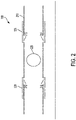
- FIG. 2 depicts schematically an aspect of the tunable organ-pipe sound source 200.
- the organ-pipe sound source 200 comprises a resonator tube 210 which acts as a simple, efficient, narrow-band, medium-output projector that operates at any ocean depth.
- the resonator tube 210 has resonator slots 215 (or vents), that are progressively covered or uncovered by symmetrically sliding coaxial tubular sleeves 220.
- the resonator tube 210 is disposed within each of the coaxial tubular sleeves 220.
- the output frequency of the tunable organ-pipe sound source 200 varies with the sleeve position.
- a computer-controlled electromechanical actuator moves the cylindrical sleeves 220 along the resonator tube 210.
- the voltage and/or current driving the acoustic driver 225 may be adjusted by means of a control device (for example, a phase-locked loop) so that the acoustic driver 225 may emit sound at the resonance frequency determined by the position of the cylindrical sleeves 220.
- a control device for example, a phase-locked loop
- the sound of the organ-pipe sound source 200 may be driven by a volume velocity acoustic driver 225.
- the acoustic driver 225 may be a piezo-ceramic sphere 2.
- the acoustic driver 225 may be a tonpilz piezo driver.
- a computer may synthesize a frequency-modulated signal to drive the acoustic driver 225 through one or more components of a drive controller.
- the drive controller may compare a phase between an output signal from a hydrophone in the resonant tube to the signal on the input of the acoustic driver 225.
- the drive controller may use a phase-lock loop (PLL) system to keep the resonator tube 210 frequency the same as that of the drive signal.
- PLL phase-lock loop
- the estimated PLL precision is better than 3 degrees of phase error.
- the use of a PLL system may maintain a small amount of error during a high rate of frequency change of the organ pipe sound source 200 output with a constant Q-factor over the working frequency band.
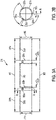
- FIGS. 3A,B illustrate engineering drawings of the resonator tube 210 that may be used in a dual frequency sound system.
- the resonator tube 210 may be made of a metal, for example aluminum.
- the resonator tube 210 may be defined by an overall length 305 from a first end to a second end.
- the resonator tube 210 may also be defined by an outer diameter 310 and an inner diameter 315.
- the resonator tube 210 may also include one or more slotted portions 320a,b disposed along the overall length 305 of the resonator tube 210, each slotted portion 320a,b comprising one or more resonator slots.
- the resonator slots of a slotted portion may all be co-radial.
- the resonator slots may be defined by a width 322a,b.
- the slotted portions 320a,b may divide the resonator tube 210 into multiple sections.
- FIG. 3A depicts an example in which two slotted portions 320a,b are illustrated.
- the slotted portions may divide the resonator tube 210 into a medial portion 340, and two terminal portions 335a,b.
- the medial portion 340 may be defined on either side by one of the slotted portions 320a,b.
- a first terminal portion 335a may be defined by a first slotted portion 320a on one side and a first end of the resonator tube 210.
- a second terminal portion 335b may be defined by a second slotted portion 320a on one side and a second end of the resonator tube 210.
- the medial portion 340 may be defined by a medial portion length 342, and each of the two terminal portions 335a,b may be defined by a terminal portion length 337a,b., respectively.
- FIG. 3B illustrates a cross sectional view of the resonator tube 210 of FIG. 3A through second slotted portion 320b at line A-A.
- FIG. 3B depicts three slots 321a-c that compose slotted portion 320b.
- Each of the resonator slots 321a-c has a slot width 322b.
- the resonator slots 352a-c may be co-radial and may be disposed equally about the resonator tube 210 at the slotted portion 320b. Between the resonator slots may be bridges 352a-c. With reference to FIG 3A , bridges 352a-c may connect the second terminal portion 335b with the medial portion 340 of the resonator tube 210.
- a similar cross section through slotted portion 320a may depict multiple resonator slots separated by multiple bridges as depicted in FIG. 3B . Additionally, a similar cross section through slotted portion 320a may depict multiple bridges configured to connect the first terminal portion 335a with the medial portion 340.
- the resonator tube 210 may have an overall length 305 of about 52.5 in., an outer diameter 310 of about 8.94 in., and an inner diameter 315 of about 8.00 in. In such an example, the resonator tube 210 may have a thickness of about 0.47 in. Additionally, in some examples, each resonator slot of the slotted sections 320a,b (for example, resonator slots 321a-c of second slotted section 320b) may have a width 322a,b of about 2.0 in.
- the first terminal portion 335a of the resonator tube 210 may be defined by an outer edge of the first slotted portion 320a and may have a first terminal portion length 337a.
- the second terminal portion 335b of the resonator tube 210 may be defined by an outer edge of the second slotted portion 320b and may have a second terminal portion length 337a.
- the medial portion 340 may be defined as the portion of the resonator tube 210 disposed between the first terminal portion 335a and the second terminal portion 335b.
- the length 337a of the first terminal portion 335a may be the same as the length 337b of the second terminal portion 335b.
- the length 337a of the first terminal portion 335a may differ from the length 337b of the second terminal portion 335b.
- the lengths 337a and 337b of the two terminal portions 335a and 335b, respectively, may be about 15.60 in.
- the length 342 of the medial portion 340 may be about 21.3 in.
- the widths 322a,b of the resonator slots of the slotted portions may be about 2.0 in. It may also be recognized that the number of resonator slots in each slotted portion is not limited to three resonator slots, such as 352a-c as illustrated in FIG. 3B .
- a slotted portion may have one resonator slot, two resonator slots, three resonator slots, four resonator slots, or any number of resonator slots that may result in the functions herein disclosed.
- Each resonator slots may be co-radial and disposed symmetrically about a longitudinal axis of the resonator tube 210 or they may be disposed asymmetrically about the longitudinal axis of the resonator tube 210.
- the length of each bridge, such as bridges 352a-c may be determined by the number, disposition, and length of the resonator slots (for example resonator slots 321a-c).
- each bridge 352a-c may have the same width of about 1.5 in. It may be recognized that the multiple bridges within one slotted portion may all have the same width or they may have different widths. Additionally, the multiples bridges within a first slotted portion may have a thickness that is the same as or differs from a thickness of the multiple bridges within a second slotted portion.
- the outer diameter 310 of the resonator tube 210 may be determined by overall length 305 of the resonator tube 210.
- the outer diameter 310 may range between a value of 0.20 times the overall length 305 of the resonator tube 210 to about 0.50 times the overall length 305 of the resonator tube 210.
- Non-limiting examples of the outer diameter 310 of the resonator tube may include about 0.20 times the overall length 305 of the resonator tube 210, about 0.25 times the overall length 305 of the resonator tube 210, about 0.30 times the overall length 305 of the resonator tube 210, about 0.35 times the overall length 305 of the resonator tube 210, about 0.40 times the overall length 305 of the resonator tube 210, about 0.45 times the overall length 305 of the resonator tube 210, about 0.50 times the overall length 305 of the resonator tube 210, or any value or range of values therebetween including endpoints.
- the widths 322a,b of the resonator slots may be determined by a radius of the resonator tube 210.
- the widths 322a,b of the resonator slots may range between a value of 0.10 times the radius of the resonator tube 210 to about 0.50 times the radius of the resonator tube 210.
- Non-limiting examples of the widths 322a,b of the resonator slots may include about 0.10 times the radius of the resonator tube 210, about 0.15 times the radius of the resonator tube 210, about 0.20 times the radius of the resonator tube 210, about 0.25 times the radius of the resonator tube 210, about 0.30 times the radius of the resonator tube 210, about 0.35 times the radius of the resonator tube 210, about 0.40 times the radius of the resonator tube 210, about 0.45 times the radius of the resonator tube 210, about 0.50 times the radius of the resonator tube 210, or any value or range of values therebetween including endpoints.
- the lengths 337a,b of the terminal portions 335a,b may be the same or they may differ.
- the thickness of the medial portion 340 may be the same as the thickness of both of the terminal portions 335a,b.
- the terminal portions 335a,b may have the same thickness which may differ from the thickness of the medial portion 340.
- the first terminal portion 335a may have a thickness that differs from the thickness of the second terminal portion 335b.
- each of the first terminal portion 335a, the medial portion 340, and the second terminal portion 335b may have a thickness that differs from the thickness of the other portions.
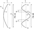
- FIGS. 4A and 4B illustrate a first acoustic mode and a second acoustic mode of an organ-pipe resonator 400, respectively.
- the organ-pipe resonator 400 may have a length 405 (denoted I) and a diameter 410 (denoted d).
- the first harmonic, f 1 may be about 500 Hz in seawater.
- the second harmonic, f 2 may be three times f 1 or about 1500 Hz.
- FIG. 4A depicts a first resonant waveform 415 corresponding to the first acoustic harmonic. It may be observed that the first resonant waveform 415 has two stable nodes 417a,b in which each of the stable nodes 417a,b is located at an end of the organ-pipe resonator 400.
- FIG. 4B depicts a second resonant waveform 425 corresponding to the second acoustic harmonic. It may be observed that the second resonant waveform 425 also has two stable nodes 427a,b in which each of the stable nodes 427a,b is located at an end of the organ-pipe resonator 400.
- the second resonant waveform 425 has a second pair of stable nodes 437a,b that may be described as internal nodes.
- a first of the second pair of stable nodes 437a may be located at a distance of about 1/3 of the length 405 of the resonator 400 from a first end of the resonator.
- a second of the second pair of stable nodes 437b may be located at a distance of about 1/3 of the length 405 of the resonator tube 400 from a second end of the resonator.
- Dotted lines 420a depict the location of the first slotted portion equivalent to 320a in FIG. 3A
- dotted lines 420b depict the location of the second slotted portion equivalent to 320b in FIG. 3A
- the slotted portions 320a,b may be positioned to correspond to the internal nodes 437a,b of the second harmonic f 2 of the organ-pipe resonator 400.
- an inner edge of the first slotted portion 320a may correspond to the location of the first internal stable node 437a.
- an inner edge of the second slotted portion 320b may correspond to the location of the second internal stable node 437b.
- an outer edge of the first slotted portion 320a may correspond to the location of the first internal stable node 437a and an outer edge of the second slotted portion 320b may correspond to the location of the second internal stable node 437b.
- the tunable organ-pipe sound source 200 may include the resonator tube 210 and multiple coaxial tubular sleeves 220.
- Each coaxial tubular sleeve 520 may have an outer diameter 510, an inner diameter 515, and a length 505.
- the coaxial tubular sleeve 520 may also include one or more bolt-holes 550a-d.
- the bolt-holes 550a-d may be configured to receive bolts to affix one or more linear actuators to the coaxial tubular sleeves 520.
- Such linear actuators may be associated with one or more transmissions each transmission comprising a lead screw and a motor.
- the linear actuators may include a metal bar having a wheel at the end thereof. The wheel of each metal bar may be configured to turn on the outer surface of the resonator tube 210 while the coaxial tubular sleeves 520 are displaced along a longitudinal axis of the resonator tube 210.
- the coaxial tubular sleeves 520 may be dimensioned so that the resonator tube 210 may be located within the interior of the tubular sleeves 520.
- the coaxial tubular sleeves 520 are configured to slide over the exterior surface of the resonator tube 210 by means of the one or more linear actuators.
- the one or more linear actuators may be moved by a transmission comprising a lead screw.
- the lead screw may be actuated by a motor powered by an electrical power source. Further, the motor may be controlled by one or more electronic controllers.
- Each coaxial tubular sleeve 520 is designed to cover or uncover one of the slotted portions 320a,b. It may be recognized that there may be as many coaxial tubular sleeves 520 as there are slotted portions 320a,b in a tunable organ-pipe sound source 200.
- the coaxial tubular sleeves 520 may be independently actuated by one or more linear actuators. In some aspects, the coaxial tubular sleeves can be actuated by one linear actuator through a lead screw transmission and move in the opposite directions symmetrically from the center of the resonant tube. In some aspects, a first coaxial tubular sleeve 520 may be actuated to slide in a direction opposite to the direction of a second coaxial tubular sleeve 520. In some aspects, a first coaxial tubular sleeve 520 may be actuated to slide in a same direction as that of a second coaxial tubular sleeve 520. In some aspects, multiple coaxial tubular sleeves 520 may be actuated together by cooperating linear actuators. In some aspects, the coaxial tubular sleeves 520 may all be moved in a concerted manner so that they all move about the same distance.
- the coaxial tubular sleeves 520 may have a length 505 of about 9.25 in. In some examples, the coaxial tubular sleeves 520 may have an outer diameter 510 of about 10.0 in. In some examples, the coaxial tubular sleeves 520 may have an inner diameter 515 of about 8.976 in. In some examples, the inner diameter 515 may be about 9 in. In such examples, the coaxial tubular sleeves 520 may have a thickness of about 0.5 in. As disclosed above, in some examples of a tunable organ-pipe sound source 200, the outer diameter of the resonator tube 210 may be about 8.94 in.
- the inner diameter 515 of the coaxial tubular sleeve 520 is about 8.976 in.
- the gap may be about 1 mm. In still other examples, the gap may be about 1.5 mm. It may be recognized that the gap between the outer surface of the resonator tube 210 and the inner surface of the coaxial tubular sleeve 520 may have any value consistent with the function of the tunable organ-pipe sound source 200.
- the value of the gap may be between about 0.4 mm and about 3.0 mm including, without limitation, a value of about 0.4 mm, about 0.45 mm, about 0.5 mm, about 0.6 mm, about 0.7 mm, about 0.8 mm. about 0.9 mm, about 1.0 mm, about 1.1, mm, about 1.2 mm, about 1.5 mm, about 1.75 mm, about 2.0 mm, about 2.5 mm, about 3.0 mm, or any value or range of values therebetween including endpoints.
- the gap may have a dimension that ranges between about 1.0 mm and about 5.0 mm, including, without limitation, about 1.0 mm, about 1.5 mm, about 2.0 mm, about 2.5 mm. about 3.0 mm, about 3.5 mm, about 4.0, mm, about 4.5 mm, about 5.0 mm, or any value or range of values therebetween including endpoints.
- the water may fill at least a portion of the interior of the resonator tube 210.
- the water disposed within the at least portion of the interior of the resonator tube 210 may be in fluid communication with the free water exterior to the organ-pipe sound source 200 via the water in the slotted sections 320a,b and the water filling the gaps between the outer surface of the resonator tube 210 and the inner surface of the coaxial tubular sleeve 520.
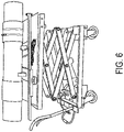
- FIG. 6 depicts a realization of a tunable organ-pipe sound source including the resonator tube and two coaxial tubular sleeves resting on a rolling jack stand.
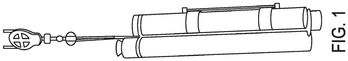
- FIG. 7 is a concept drawing of one aspect of an underwater sound system 700.
- the sound system may be composed of an organ-pipe sound source 705, a transmission assembly 750, and deep water pressure housing 760.
- the organ-pipe sound source 705 includes a resonator tube 710 disposed within a pair of coaxial tubular sleeves 730a,b.
- the resonator tube 710 is divided by two slotted portions 720a,b into a first terminal portion 712a (bounded by a first end of the resonator tube 710 and a first edge of first slotted portion 720a), a second terminal portion 712b (bounded by a second end of the resonator tube 710 and a first edge of second slotted portion 720a), and a medial portion 714 (bounded by a second edge of the first slotted portion 720a and a second edge of the second slotted portion 720b).
- first slotted portion 720a is composed of at least two slots 722a and at least two bridges 724a.
- the at least two bridges 724a form end boundaries of at least two resonator slots 722a and are configured to mechanically link the first terminal portion 712a with the medial portion 714.
- the first slotted portion 720a is composed of more than one slot 722a, the multiple slots 722a are co-radial.
- the second slotted portion 720b is composed of at least two resonator slots 722b and at least two ridges 724b.
- the at least two bridges 724b form end boundaries of the at least two resonator slots 722b and are configured to mechanically link the second terminal portion 712b with the medial portion 714.
- the second slotted portion 720b is composed of more than one slot 722b, the multiple slots 722b are co-radial.
- Each of the coaxial tubular sleeves 730a,b is configured to slide on the outer surface of the resonator tube 710 and to slidably occlude one of each of the slotted portions 720a,b.
- the transmission assembly 750 may include a motor 752 configured to rotate a lead screw 754. Rotation of the lead screw 754 may cause a linear motion of the sleeve brackets 756a,b.
- the linear motion of sleeve bracket 756a may cause coaxial tubular sleeve 730a to slide along the outer surface of the resonator tube 710 and to cover or uncover slotted portion 720a.
- the linear motion of sleeve bracket 756b may cause coaxial tubular sleeve 730b to slide along the outer surface of the resonator tube 710 and to cover or uncover slotted portion 720b.
- the motions of sleeve brackets 756a,b may be coordinated and to move symmetrically in opposing directions.
- the lead screw 754 or the transmission may be covered by one or more rubber bellows filled with oil to protect the lead screw 754 from corrosion when submerged under water.
- Deep water pressure housing 760 may serve as a mechanical mounting structure for the transmission assembly 750 and or the organ-pipe sound source 705.
- the deep water pressure housing 760 may also house various components including a power supply for the motor 752, an electronic control assembly, a general purpose computer system, and a communication system.
- the electronic control assembly may include those electronic components configured to control the motion of the motor 752, including the direction of the motor rotation and the speed and acceleration of motor rotation.
- the general purpose computer system may include any one or more components which, without limitation, may include one or more processor or microprocessors, one or more memory components (including, without limitation, one or more static or dynamic memory components), and one or more interface components.
- the memory components may include instructions that, when executed by the processor or microprocessor, cause the processor or microprocessor to calculate parameters related to the operations of the underwater sound system 700.
- the instructions may also result in the processor or microprocessor directing the operations of the components of the underwater sound system 700, including, without limitation, directing the motor to adjust the positions of the coaxial tubular sleeves 730a,b via the control system and to adjust the output frequency of the a controllable acoustical driver.
- the interface components may also permit the one or more processors or microprocessors to transmit and/or receive data via the communication system.
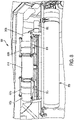
- FIG. 8 illustrates a realization of the underwater sound system 800 as depicted in FIG. 7 .
- Components depicted in FIG. 8 are the deep water pressure housing 860, actuator motor 852, the medial portion 814 and two terminal portions 812a,b of the resonator tube and the coaxial tubular sleeves 830a,b.
- FIG. 8 also depicts wheeled stabilizer bars 870 that are mechanically associated with the coaxial tubular sleeves 830a,b.
- the stabilizer bars 870 may help stabilize the motion of the coaxial tubular sleeves 830a,b as the slide on the exterior surface of the resonator tube. In particular, they may prevent an edge of one of the coaxial tubular sleeves 830a,b from catching an edge of a resonator slot in the slotted portions.
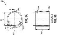
- FIG. 9A depicts an organ-pipe sound source in a first configuration 905a in which the coaxial tubular sleeves 920a completely cover the slotted portions 921.
- FIG. 9B depicts an organ-pipe sound source in a second configuration 905b in which the coaxial tubular sleeves 920b completely uncover the slotted portions 921.
- the driving oscillator 925 imparts an oscillating pressure force to water in the interior 932 of the resonator tube. The pressure force is primarily transmitted to the exterior of the resonator tube at the tube ends.
- the gap 934 may have a length 936 as measured from the center of the resonator slot 922 to the closer end of the coaxial sleeve 920a,b. It may be recognized that, due to the surface tension of the water against the two surfaces, the water in the gap 934 presents a high impedance acoustic path to the exterior of the resonator tube 910.
- the water oscillation is primarily at the first resonant frequency of the resonator tube 910.
- the coaxial tubular sleeve 920b is configured to completely uncover the resonator slots 922.
- the resonator slots 922 present a direct and low impedance path to the water in the exterior of the resonator tube. Because the resonator slots 922 are located approximately at the interior nodes of the second resonant frequency of the resonator tube, the resonator tube emits sound waves at the second resonant frequency. It may be recognized that the motion of the coaxial tubular sleeve 920a,b relative to the resonator slots 922 will result in a change in the length 936 of the gaps 934.
- the motion of the coaxial tubular sleeve 920a,b will therefore change the acoustic impedance coupling through the gap 934 due to the change in the length 936 of the gap 934.
- This impedance coupling will be at a maximum in configuration 905a, in which the resonator slots 922 and slotted portion 921 are completely covered.
- This impedance coupling will be at a minimum in configuration 905b, in which the resonator slots 922 and slotted portion 921 are completely uncovered.
- Finite element analysis simulations have been calculated to determine the output of an organ-pipe sound source substantially as disclosed above in FIGS. 2 , 3A , 3B , 5A, and 5B .
- Table 1 displays the organ pipe configuration used in the calculations.
- FIG. 10 depicts the finite element analysis (FEA) mesh used to calculate the sound pressure output of an organ-pipe sound source having dimensions disclosed in Table 1 above. Because the organ-pipe sound source is axially symmetric, a two-dimensional axially symmetric simulation was run. As indicated in FIG. 10 , the center of the organ-pipe sound source (corresponding to x/y coordinates 0/0) is equally offset from each of the two ends of the resonator tube and located along the central longitudinal axis of the resonator tube. The X and Y axes are labeled in meters from the center of the sound source.
- FEA finite element analysis
- each coaxial sleeve was positioned so that the longitudinal center of the coaxial sleeve was positioned directly over the respective center of the slotted portion.
- Each sleeve was then slidably moved to a respective terminal end of the resonator tube in increments of 2 cm. The sleeves were moved symmetrically during the simulation.
- FIGS. 11A and 11B depict results of FEA simulations for an organ-pipe sound source having the resonator slots completely covered by the coaxial sleeves ( FIGS. 11A ) and for an organ-pipe sound source having the resonator slots completely uncovered by the coaxial sleeves ( FIGS. 11B ).
- the sound pressure level (SPL) in dB re I uPa is shown in FIG. 11A at an initial frequency of about 500 Hz, when the resonator slots were completely closed, and in FIG. 11B at a final frequency, when the resonator slots were completely opened.
- FIG. 12 depicts another graph of the absolute pressure (Pa) contours generated by the FEA simulation for the resonator tube having the resonator slots completely uncovered (frequency at about 1063Hz).
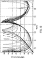
- the resonator slots are symmetrically located at a distance of about 1/3 from the resonator tube edges, where the second harmonic of the resonator tube has internal nodes. According to the simulation, the motion of the coaxial sleeves with respect to the resonator slots should have a minor effect on the second harmonic frequency. Additionally, the resonance frequency of the first harmonic can be moved toward the resonance frequency of the second harmonic. This behavior is depicted in FIG. 13 which is set of frequency responses of the sound system for shifts of the coaxial sleeves.
- the sleeve length was 9.5" (24cm), and was shifted from a first configuration (slotted portions completely covered as depicted in FIG 9A ) to a second configuration (slotted portions completely uncovered as depicted in FIG. 9B ).
- the frequency responses were calculated for a symmetric shift of 1 cm for the two coaxial tubes. It may be observed that the first resonance (first harmonic) changes from about 500 Hz to about 1050 Hz, while the second resonance (second harmonic) changes from about 1250 Hz to about 1400 Hz, which corresponds to only about a 12% change Between the resonance peaks, the pressure level amplitude drops more then 10 times (-20 dB).
- the change in the first harmonic resonant frequency may be due to a change in the acoustic coupling between the water in the interior of the pipe and the exterior via the water in the gaps.
- the acoustic impedance coupling therethrough decreases.
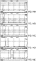
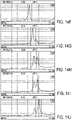
- FIGS. 14A-J are amplitude versus frequency measurements of the acoustic output of the test device as the coaxial sleeves are synchronously and symmetrically moved in 2 cm increments from an initial configuration of the resonator slots being completely covered (center of the coaxial sleeve initially located over the center of the resonator slot).
- the frequency of the first harmonic resonance increases as the coaxial sleeves are moved, in a manner similar to that depicted in FIG. 13 (simulation values).
- a second resonance begins to appear when the first harmonic resonance frequency reaches a value of about 874.37189 Hz ( FIG. 14G ).
- the dual resonance depicted in FIG. 14G occurs after each of the coaxial sleeves is displaced 12 cm. If the center of the coaxial sleeves (total length 9.25 in. or about 23.5 cm) are located initially at the center of the resonator slots (width about 2 in. or about 5 cm), then the second resonance peak is observed when the edge of the coaxial sleeves have uncovered about 2.75 cm of the resonator slot.
- the resonator slot width is much larger that the width along the tube axis and the resonator slots are opened widely (for example, more than 2"), then the multiple resonances appear.
- the width of the resonator slot may be fashioned to be about 1/2 of a radius of the inner diameter of the resonator tube.
- the resonator tube acts as a single resonator in which the two terminal portions and the medial portion of the resonator tube are strongly acoustically coupled.
- the coupling among the three tube portions weakens considerably, and the portions begin to act as individual resonators.
- the present simulation did not predict this effect because the present simulation only considered acoustic coupling through the water, including the water in the resonator tube interior and the gaps, and did not include acoustic coupling among the tube the portions via the metal bridges.
- the two first harmonic resonance peaks depicted in FIGS. 14G-J are due to independent resonances of the medial portion and the two terminal portions.
- the first harmonic resonance may be split into two resonance peaks. The difference in the frequencies may be related to the relative differences of the lengths of the tube portions.
- three first harmonic resonance peaks may be produced by an organ-pipe sound source if the tube portions -- that is, a first terminal portion, the medial portion, and a second terminal portion -- do not have a common tube length.
- the frequencies at the first harmonic may also be dependent on the relative thickness of the tubes comprising the portions.
- any one or more of the portions of the resonator tube may have a wall thickness about 1/8th of a radius of the inner diameter of the resonator tube. Additional adjustments to the multiple frequencies at the first harmonic may also be obtained by fabricating the resonator tube portions with different tube thicknesses. It may be recognized that the multiple first harmonic frequencies may be adjusted close to each other with very small amplitude variability over the working frequency band.
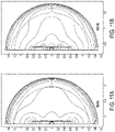
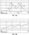
- FIGS. 15A and 15B depict the real and imaginary components, respectfully, of the admittance of a tunable organ-pipe sound source as disclosed above in which the resonator slots of the slotted portions are completely uncovered by the coaxial sleeves.
- a tunable organ-pipe sound source in this configuration may therefore act as a broadband sound source having an output defined by the frequency response of the resonator tube.
- the frequency response of the resonator tube may be composed of a dual resonance transfer function defined by a first resonance frequency and a second resonance frequency. It can be observed that the output of the sound source in this configuration has the dual resonance frequencies (1505 and 1510) both having about the same amplitude.
- the dual resonance frequencies (1505 and 1510) both having about the same amplitude.
- the higher frequency resonance peak 1505 has a frequency of about 940 Hz and the lower frequency resonance peak 1510 has a frequency of about 890 Hz.
- the two resonances may be disposed between the first harmonic (at about 500 Hz) and the second harmonic (at about 1500 Hz) of the resonant tube.
- the first resonance peak 1505 and the second resonance peak 1510 may define a communication bandwidth 1530 for transmitting one or more information-containing signals underwater.
- a communication bandwidth 1530 may be about 100 Hz and include frequencies between a lower limit 1525 of about 845 Hz and an upper limit 1520 of about 955Hz 1520 and centered at a medial frequency 1515 of about 915Hz.
- the medial frequency 1515 may be an average of the frequency of the first resonance peak 1505 and the frequency of the second resonance peak 1510.
- the communication bandwidth 1530 may be chosen to have a frequency of about 10% to about 15% of the medial frequency 1515.
- the communication bandwidth may have a frequency of about 10% of the medial frequency 1515, of about 11% of the medial frequency 1515, of about 12% of the medial frequency 1515, of about 13% of the medial frequency 1515, of about 14% of the medial frequency 1515, of about 15% of the medial frequency 1515, or any such percentage or range of percentages therebetween including endpoints. This bandwidth may be sufficient for a long range underwater communication system for a precise underwater positioning support.
- FIG. 15B depicts the imaginary or phase-related components of the tunable organ-pipe sound source as disclosed above in which the resonator slots of the slotted portions are completely uncovered by the coaxial sleeves. It may be noted that over the range of frequencies measured, little phase variability is observed at the frequencies corresponding to the two resonance peaks (1505 and 1510) corresponding to the characteristic resonance frequencies of the organ-pipe operating in the broadband mode.
- a tunable organ-pipe sound source is composed of the broadband organ-pipe sound source disposed within the coaxial tubular sleeves.
- Such a device may operate in two signal transmission modes.
- the slotted portions may be covered by the coaxial tubular sleeves which may be slid along the exterior surface of the resonant tube to select a resonant output frequency.
- the controller of the acoustical driver may control the frequency output of the acoustical driver to match the resonant output frequency determined by the position of the coaxial tubular sleeves.
- the tunable organ-pipe sound source may be programmed to transmit single frequency pulses, frequency modulated pulses, chirps, or linear swept-frequency signals.
- the coaxial tubular sleeves When operated in the second signal transmission mode, the coaxial tubular sleeves may be fixed at a position to uncover the slots in the slotted portions of the resonant tube.
- the tunable organ-pipe sound source may function like the broadband organ-pipe sound source disclosed above.
- electrical circuitry includes, but is not limited to, electrical circuitry having at least one discrete electrical circuit, electrical circuitry having at least one integrated circuit, electrical circuitry having at least one application specific integrated circuit, electrical circuitry forming a general purpose computing device configured by a computer program (e.g., a general purpose computer configured by a computer program which at least partially carries out processes and/or devices described herein, or a microprocessor configured by a computer program which at least partially carries out processes and/or devices described herein), electrical circuitry forming a memory device (e.g., forms of random access memory), and/or electrical circuitry forming
- Examples of a signal bearing medium include, but are not limited to, the following: a recordable type medium such as a floppy disk, a hard disk drive, a Compact Disc (CD), a Digital Video Disk (DVD), a digital tape, a computer memory, etc.; and a transmission type medium such as a digital and/or an analog communication medium (e.g., a fiber optic cable, a waveguide, a wired communications link, a wireless communication link (e.g., transmitter, receiver, transmission logic, reception logic, etc.), etc.).
- a recordable type medium such as a floppy disk, a hard disk drive, a Compact Disc (CD), a Digital Video Disk (DVD), a digital tape, a computer memory, etc.
- a transmission type medium such as a digital and/or an analog communication medium (e.g., a fiber optic cable, a waveguide, a wired communications link, a wireless communication link (e.g., transmitter, receiver, transmission logic, reception
- any two components so associated can also be viewed as being “operably connected,” or “operably coupled,” to each other to achieve the desired functionality, and any two components capable of being so associated can also be viewed as being “operably couplable,” to each other to achieve the desired functionality.
- operably couplable include but are not limited to physically mateable and/or physically interacting components, and/or wirelessly interactable, and/or wirelessly interacting components, and/or logically interacting, and/or logically interactable components.
- Coupled and “connected” along with their derivatives. It should be understood that these terms are not intended as synonyms for each other. For example, some aspects may be described using the term “connected” to indicate that two or more elements are in direct physical or electrical contact with each other. In another example, some aspects may be described using the term “coupled” to indicate that two or more elements are in direct physical or electrical contact. The term “coupled,” however, also may mean that two or more elements are not in direct contact with each other, but yet still cooperate or interact with each other.
- one or more components may be referred to herein as “configured to,” “configurable to,” “operable/operative to,” “adapted/adaptable,” “able to,” “conformable/conformed to,” etc.
- “configured to” can generally encompass active-state components and/or inactive-state components and/or standby-state components, unless context requires otherwise.
Landscapes
- Engineering & Computer Science (AREA)
- Physics & Mathematics (AREA)
- Acoustics & Sound (AREA)
- Remote Sensing (AREA)
- Life Sciences & Earth Sciences (AREA)
- Multimedia (AREA)
- General Physics & Mathematics (AREA)
- General Life Sciences & Earth Sciences (AREA)
- Geology (AREA)
- Geophysics (AREA)
- Environmental & Geological Engineering (AREA)
- Mechanical Engineering (AREA)
- Signal Processing (AREA)
- Health & Medical Sciences (AREA)
- Otolaryngology (AREA)
- Transducers For Ultrasonic Waves (AREA)
- Details Of Audible-Bandwidth Transducers (AREA)
- Obtaining Desirable Characteristics In Audible-Bandwidth Transducers (AREA)
- Measurement Of Velocity Or Position Using Acoustic Or Ultrasonic Waves (AREA)
Claims (12)
- Unterwasserschallquelle, die Folgendes umfasst:einen akustischen Treiber (225);eine Steuervorrichtung des akustischen Treibers;ein tauchfähiges Resonatorrohr (210), das mit dem akustischen Treiber akustisch gekoppelt ist, wobei der tauchfähige Resonator konfiguriert ist, um in Wasser eingetaucht zu werden, wobei das Resonatorrohr ferner Folgendes umfasst:einen Innenanteil, der konfiguriert ist, um einen Anteil des Wassers aufzunehmen;einen ersten geschlitzten Anteil (320a), der erste wenigstens zwei koradiale Resonatorschlitze umfasst; undeinen zweiten geschlitzten Anteil (320b), der zweite wenigstens zwei koradiale Resonatorschlitze (321a, 321b) umfasst,wobei eine Gesamtlänge (305) des Resonatorrohrs mehrere Oberwellen des Resonatorrohrs definiert,wobei der erste geschlitzte Anteil (320a) an einer ersten Position entlang der Gesamtlänge des Resonatorrohrs gelegen ist, die einem ersten Knoten einer der mehreren Oberwellen entspricht,wobei der zweite geschlitzte Anteil (320b) an einer zweiten Position entlang der Gesamtlänge des Resonatorrohrs gelegen ist, die einem zweiten Knoten einer der mehreren Oberwellen entspricht, undwobei die Steuervorrichtung des akustischen Treibers konfiguriert ist, um ein Ausgangssignal der Unterwasserschallquelle innerhalb einer Bandbreite zu steuern, die durch eine Frequenzantwort des Resonatorrohrs definiert ist; undeine erste koaxiale röhrenförmige Hülse (220) und eine zweite koaxiale röhrenförmige Hülse (220),wobei die erste koaxiale röhrenförmige Hülse konfiguriert ist, um auf einen ersten Anteil der Außenoberfläche des Resonatorrohrs zu gleiten, und die zweite koaxiale röhrenförmige Hülse konfiguriert ist, um auf einen zweiten Anteil der Außenoberfläche des Resonatorrohrs zu gleiten,wobei die Unterwasserschallquelle konfiguriert ist, um in einem ersten akustischen Modus in Betrieb zu sein, wenn der erste geschlitzte Anteil durch die erste koaxiale röhrenförmige Hülse bedeckt ist und der zweite geschlitzte Anteil durch die zweite koaxiale röhrenförmige Hülse bedeckt ist,wobei die Unterwasserschallquelle konfiguriert ist, um in einem zweiten akustischen Modus in Betrieb zu sein, wenn der erste geschlitzte Anteil durch die erste koaxiale röhrenförmige Hülse aufgedeckt ist und der zweite geschlitzte Anteil durch die zweite koaxiale röhrenförmige Hülse aufgedeckt ist, unddadurch gekennzeichnet, dass:wobei der erste Anteil (335a) einer Außenoberfläche des Resonatorrohrs innerhalb der ersten koaxialen röhrenförmigen Hülse angeordnet ist, wobei dadurch ein erster Spalt (934) zwischen einem ersten Anteil der Außenoberfläche des Resonatorrohrs und einer Innenoberfläche der ersten koaxialen röhrenförmigen Hülse ausgebildet wird, und der zweite Anteil (335b) der Außenoberfläche des Resonatorrohrs innerhalb der zweiten koaxialen röhrenförmigen Hülse angeordnet ist, wobei dadurch ein zweiter Spalt zwischen dem zweiten Anteil der Außenoberfläche des Resonatorrohrs und einer Innenoberfläche der zweiten koaxialen röhrenförmigen Hülse ausgebildet wird,wobei das Resonatorrohr, wenn es in dem zweiten akustischen Modus betrieben wird, einen Breitband-Doppelresonanz-Frequenzgang, der durch eine erste Resonanzfrequenz und eine zweite Resonanzfrequenz definiert ist, und eine Breitband-Frequenzbandbreite zwischen 10 % und 15 % einer Mittelfrequenz aufweist, die als ein Durchschnitt der ersten Resonanzfrequenz und der zweiten Resonanzfrequenz definiert ist, einschließlich der ersten Resonanzfrequenz und der zweiten Resonanzfrequenz, und wobei die Resonatorschlitzbreite senkrecht zu der Resonatorrohrachse viel größer als die Breite der Schlitze entlang der Resonatorrohrachse ist.
- Unterwasserschallquelle nach Anspruch 1, wobei das Resonatorrohr einen äußeren Durchmesser innerhalb eines Bereichs von einem Zehntel der Gesamtlänge des Resonatorrohrs bis zu einer Hälfte der Gesamtlänge des Resonatorrohrs aufweist.
- Unterwasserschallquelle nach Anspruch 1, wobei jeder der ersten wenigstens zwei koradialen Resonatorschlitze des ersten geschlitzten Anteils eine Breite entlang der Resonatorrohrachse innerhalb eines Bereichs von einem Zehntel eines Radius des Resonatorrohrs und einer Hälfte des Radius des Resonatorrohrs aufweist, und wobei jeder der zweiten wenigstens zwei koradialen Resonatorschlitze des zweiten geschlitzten Anteils eine Breite entlang der Resonatorrohrachse innerhalb eines Bereichs von einem Zehntel des Radius des Resonatorrohrs und einer Hälfte des Radius des Resonatorrohrs aufweist.
- Unterwasserschallquelle nach Anspruch 1, wobei der erste geschlitzte Anteil und der zweite geschlitzte Anteil einen Mittelabschnitt des Resonatorrohrs dazwischen definieren,wobei der erste geschlitzte Anteil und ein erstes Ende des Resonatorrohrs einen ersten Endabschnitt des Resonatorrohrs dazwischen definieren, undwobei der zweite geschlitzte Anteil und ein zweites Ende des Resonatorrohrs einen zweiten Endabschnitt des Resonatorrohrs dazwischen definieren.
- Unterwasserschallquelle nach Anspruch 4, wobei der erste Endabschnitt eine erste Abschnittslänge aufweist, der zweite Endabschnitt eine zweite Abschnittslänge aufweist und der Mittelabschnitt eine Mittelabschnittslänge aufweist und wobei die Mittelabschnittslänge sich von der ersten Abschnittslänge unterscheidet und die Mittelabschnittslänge sich von der zweiten Länge unterscheidet.
- Unterwasserschallquelle nach Anspruch 4, wobei die wenigstens zwei koradialen Resonatorschlitze des ersten geschlitzten Anteils durch eine erste Brücke getrennt sind, die ein erstes Ende des Mittelabschnitts und ein erstes Ende des ersten Endabschnitts verbindet, und
wobei die wenigstens zwei koradialen Resonatorschlitze des zweiten geschlitzten Anteils durch eine zweite Brücke getrennt sind, die ein zweites Ende des Mittelabschnitts und ein erstes Ende des zweiten Endabschnitts verbindet. - Unterwasserschallquelle nach Anspruch 1, wobei die Unterwasserschallquelle konfiguriert ist, um in einem ersten akustischen Modus in Betrieb zu sein, wenn der erste geschlitzte Anteil wenigstens teilweise durch die erste koaxiale röhrenförmige Hülse bedeckt ist und der zweite geschlitzte Anteil wenigstens teilweise durch die zweite koaxiale röhrenförmige Hülse bedeckt ist, und
wobei das Resonatorrohr in der ersten akustischen Konfiguration einen Resonanzfrequenzgang aufweist, in dem sich ein Wert der ersten Resonanzfrequenz als Reaktion auf einen Betrag, um den die erste koaxiale röhrenförmige Hülse den ersten geschlitzten Anteil bedeckt, und einen Betrag, um den die zweite koaxiale röhrenförmige Hülse den zweiten geschlitzten Anteil bedeckt, ändert. - Unterwasserschallquelle nach Anspruch 1, wobei der erste Spalt eine Breite in einem Bereich zwischen 1 mm und 5 mm aufweist und der zweite Spalt eine Breite in einem Bereich zwischen 1 mm und 5 mm aufweist.
- Unterwasserschallquelle nach Anspruch 7, wobei die Steuervorrichtung des akustischen Treibers konfiguriert ist, um eine Ausgangsfrequenz des akustischen Treibers auf eine Rohrresonanzfrequenz zu steuern, die wenigstens in Teilen durch eine Lage der ersten koaxialen röhrenförmigen Hülse hinsichtlich des ersten geschlitzten Anteils und eine Lage der zweiten koaxialen röhrenförmigen Hülse hinsichtlich des zweiten geschlitzten Anteils bestimmt wird, wenn die Unterwasserschallquelle konfiguriert ist, um in dem ersten akustischen Modus in Betrieb zu sein.
- Unterwasserschallquelle nach Anspruch 7, wobei das Resonatorrohr in der ersten akustischen Konfiguration einen Resonanzfrequenzgang aufweist, in dem sich ein Wert einer zweiten Resonanzfrequenz als Reaktion auf einen Betrag, um den die erste koaxiale röhrenförmige Hülse den ersten geschlitzten Anteil bedeckt, und einen Betrag, um den die zweite koaxiale röhrenförmige Hülse den zweiten geschlitzten Anteil bedeckt, ändert, und wobei die zweite Resonanzfrequenz nicht einem zweiten harmonischen Modus des Resonatorrohrs entspricht.
- Unterwasserschallquelle nach Anspruch 10, wobei eine Amplitude der ersten Resonanzfrequenz und eine Amplitude der zweiten Resonanzfrequenz von einem Betrag abhängig sind, um den die erste koaxiale röhrenförmige Hülse die ersten wenigstens zwei koradialen Resonatorschlitze bedeckt, und einem Betrag, der die zweite koaxiale röhrenförmige Hülse die zweiten wenigstens zwei koradialen Resonatorschlitze bedeckt.
- Verfahren zum Übertragen von Signalen unter Wasser, das Folgendes umfasst:Bereitstellen der Unterwasserschallquelle nach Anspruch 1; undErzeugen, durch den akustischen Treiber, einer akustischen Ausgabe, die eine Frequenz innerhalb der Breitband-Frequenzbandbreite aufweist.
Applications Claiming Priority (1)
| Application Number | Priority Date | Filing Date | Title |
|---|---|---|---|
| US201762485177P | 2017-04-13 | 2017-04-13 |
Publications (3)
| Publication Number | Publication Date |
|---|---|
| EP3398693A2 EP3398693A2 (de) | 2018-11-07 |
| EP3398693A3 EP3398693A3 (de) | 2019-03-06 |
| EP3398693B1 true EP3398693B1 (de) | 2022-05-18 |
Family
ID=62002035
Family Applications (1)
| Application Number | Title | Priority Date | Filing Date |
|---|---|---|---|
| EP18167376.5A Active EP3398693B1 (de) | 2017-04-13 | 2018-04-13 | Niederfrequente breitband-schallquelle für unterwassernavigation und -kommunikation |
Country Status (4)
| Country | Link |
|---|---|
| US (1) | US10424284B2 (de) |
| EP (1) | EP3398693B1 (de) |
| JP (1) | JP7008567B2 (de) |
| CA (1) | CA3001189C (de) |
Families Citing this family (5)
| Publication number | Priority date | Publication date | Assignee | Title |
|---|---|---|---|---|
| US10901102B2 (en) | 2015-04-09 | 2021-01-26 | Teledyne Instruments, Inc. | Digital seismic source signature near-field hydrophone |
| US10476604B2 (en) | 2017-06-28 | 2019-11-12 | Teledyne Instruments, Inc. | Transmitter-receiver separation system for full-duplex underwater acoustic communication system |
| US10882592B1 (en) * | 2020-04-15 | 2021-01-05 | Teledyne Instruments, Inc. | Mobile low frequency sound source for underwater communication and navigation |
| US11661160B1 (en) | 2021-11-18 | 2023-05-30 | Teledyne Instruments, Inc. | Low frequency sound source for long-range glider communication and networking |
| CN116913235B (zh) * | 2023-09-14 | 2023-12-26 | 中石化经纬有限公司 | 一种低频宽带偶极子声源 |
Family Cites Families (7)
| Publication number | Priority date | Publication date | Assignee | Title |
|---|---|---|---|---|
| US3986669A (en) * | 1976-03-23 | 1976-10-19 | Martner John G | Ultrasonic tubular emulsifier and atomizer apparatus and method |
| EP0006833B1 (de) * | 1978-07-03 | 1983-09-14 | Mats Olsson Konsult Ab | Niederfrequenz Schallgeber |
| US4855964A (en) | 1988-07-08 | 1989-08-08 | Her Majesty The Queen In Right Of Canada, As Represented By The Minister Of National Defence Of Her Majesty's Canadian Government | Vented-pipe projector |
| US8400872B2 (en) | 2009-09-25 | 2013-03-19 | Acoustic Zoom, Inc. | Seismic source which incorporates earth coupling as part of the transmitter resonance |
| US8441892B2 (en) * | 2011-03-21 | 2013-05-14 | Teledyne Instruments, Inc. | Gas-filled bubble seismo-acoustic source |
| US8634276B2 (en) * | 2011-03-21 | 2014-01-21 | Teledyne Instruments, Inc. | Tunable bubble sound source |
| US8670293B2 (en) | 2011-03-25 | 2014-03-11 | Woods Hole Oceanographic Institution | Broadband sound source for long distance underwater sound propagation |
-
2018
- 2018-04-12 CA CA3001189A patent/CA3001189C/en active Active
- 2018-04-13 JP JP2018077618A patent/JP7008567B2/ja active Active
- 2018-04-13 US US15/952,334 patent/US10424284B2/en active Active
- 2018-04-13 EP EP18167376.5A patent/EP3398693B1/de active Active
Also Published As
| Publication number | Publication date |
|---|---|
| US10424284B2 (en) | 2019-09-24 |
| EP3398693A2 (de) | 2018-11-07 |
| CA3001189A1 (en) | 2018-10-13 |
| EP3398693A3 (de) | 2019-03-06 |
| JP2018198419A (ja) | 2018-12-13 |
| CA3001189C (en) | 2023-10-10 |
| JP7008567B2 (ja) | 2022-01-25 |
| US20190057680A1 (en) | 2019-02-21 |
Similar Documents
| Publication | Publication Date | Title |
|---|---|---|
| EP3398693B1 (de) | Niederfrequente breitband-schallquelle für unterwassernavigation und -kommunikation | |
| US8441892B2 (en) | Gas-filled bubble seismo-acoustic source | |
| US8634276B2 (en) | Tunable bubble sound source | |
| US8400872B2 (en) | Seismic source which incorporates earth coupling as part of the transmitter resonance | |
| US10401511B2 (en) | Dual resonant single aperture seismic source | |
| US8670293B2 (en) | Broadband sound source for long distance underwater sound propagation | |
| CN106133272B (zh) | 变化厚度声学换能器 | |
| EP3329303B1 (de) | Doppeltresonante seismische quelle | |
| Morozov et al. | High-efficient tunable sound sources for ocean and bottom tomography, 15 years of operating history | |
| Morozov | Modeling and Testing of Carbon-Fiber Doubly-Resonant Underwater Acoustic Transducer | |
| Morozov | Tunable and broadband resonator pipe sound sources for ocean acoustic tomography, communications and long-range navigation | |
| Morozov et al. | Underwater acoustic technologies for long-range navigation and communications in the Arctic | |
| Morozov et al. | The new development of the autonomous sources for ocean acoustic navigation, tomography and communications | |
| WO2021010949A1 (en) | Broadband ultrasonic transducer assembly with acoustic lens | |
| Everest et al. | Acoustical characteristics of noise produced by snapping shrimp | |
| Morozov | Simulation and Testing of a Tunable Organ Pipe for Ocean Acoustic Tomography |
Legal Events
| Date | Code | Title | Description |
|---|---|---|---|
| PUAI | Public reference made under article 153(3) epc to a published international application that has entered the european phase |
Free format text: ORIGINAL CODE: 0009012 |
|
| STAA | Information on the status of an ep patent application or granted ep patent |
Free format text: STATUS: REQUEST FOR EXAMINATION WAS MADE |
|
| 17P | Request for examination filed |
Effective date: 20180413 |
|
| AK | Designated contracting states |
Kind code of ref document: A2 Designated state(s): AL AT BE BG CH CY CZ DE DK EE ES FI FR GB GR HR HU IE IS IT LI LT LU LV MC MK MT NL NO PL PT RO RS SE SI SK SM TR |
|
| AX | Request for extension of the european patent |
Extension state: BA ME |
|
| PUAL | Search report despatched |
Free format text: ORIGINAL CODE: 0009013 |
|
| AK | Designated contracting states |
Kind code of ref document: A3 Designated state(s): AL AT BE BG CH CY CZ DE DK EE ES FI FR GB GR HR HU IE IS IT LI LT LU LV MC MK MT NL NO PL PT RO RS SE SI SK SM TR |
|
| AX | Request for extension of the european patent |
Extension state: BA ME |
|
| RIC1 | Information provided on ipc code assigned before grant |
Ipc: H04R 17/00 20060101ALI20190131BHEP Ipc: H04R 3/04 20060101ALI20190131BHEP Ipc: H04R 1/34 20060101ALI20190131BHEP Ipc: G01V 1/02 20060101ALI20190131BHEP Ipc: G10K 11/04 20060101ALI20190131BHEP Ipc: H04R 1/44 20060101ALI20190131BHEP Ipc: H04R 1/28 20060101ALI20190131BHEP Ipc: B06B 1/20 20060101AFI20190131BHEP |
|
| STAA | Information on the status of an ep patent application or granted ep patent |
Free format text: STATUS: EXAMINATION IS IN PROGRESS |
|
| 17Q | First examination report despatched |
Effective date: 20201015 |
|
| GRAP | Despatch of communication of intention to grant a patent |
Free format text: ORIGINAL CODE: EPIDOSNIGR1 |
|
| STAA | Information on the status of an ep patent application or granted ep patent |
Free format text: STATUS: GRANT OF PATENT IS INTENDED |
|
| INTG | Intention to grant announced |
Effective date: 20211209 |
|
| GRAS | Grant fee paid |
Free format text: ORIGINAL CODE: EPIDOSNIGR3 |
|
| GRAA | (expected) grant |
Free format text: ORIGINAL CODE: 0009210 |
|
| STAA | Information on the status of an ep patent application or granted ep patent |
Free format text: STATUS: THE PATENT HAS BEEN GRANTED |
|
| AK | Designated contracting states |
Kind code of ref document: B1 Designated state(s): AL AT BE BG CH CY CZ DE DK EE ES FI FR GB GR HR HU IE IS IT LI LT LU LV MC MK MT NL NO PL PT RO RS SE SI SK SM TR |
|
| REG | Reference to a national code |
Ref country code: GB Ref legal event code: FG4D |
|
| REG | Reference to a national code |
Ref country code: CH Ref legal event code: EP |
|
| REG | Reference to a national code |
Ref country code: IE Ref legal event code: FG4D |
|
| REG | Reference to a national code |
Ref country code: DE Ref legal event code: R096 Ref document number: 602018035676 Country of ref document: DE |
|
| REG | Reference to a national code |
Ref country code: AT Ref legal event code: REF Ref document number: 1492848 Country of ref document: AT Kind code of ref document: T Effective date: 20220615 |
|
| REG | Reference to a national code |
Ref country code: LT Ref legal event code: MG9D |
|
| REG | Reference to a national code |
Ref country code: NL Ref legal event code: MP Effective date: 20220518 |
|
| REG | Reference to a national code |
Ref country code: AT Ref legal event code: MK05 Ref document number: 1492848 Country of ref document: AT Kind code of ref document: T Effective date: 20220518 |
|
| PG25 | Lapsed in a contracting state [announced via postgrant information from national office to epo] |
Ref country code: SE Free format text: LAPSE BECAUSE OF FAILURE TO SUBMIT A TRANSLATION OF THE DESCRIPTION OR TO PAY THE FEE WITHIN THE PRESCRIBED TIME-LIMIT Effective date: 20220518 Ref country code: PT Free format text: LAPSE BECAUSE OF FAILURE TO SUBMIT A TRANSLATION OF THE DESCRIPTION OR TO PAY THE FEE WITHIN THE PRESCRIBED TIME-LIMIT Effective date: 20220919 Ref country code: NO Free format text: LAPSE BECAUSE OF FAILURE TO SUBMIT A TRANSLATION OF THE DESCRIPTION OR TO PAY THE FEE WITHIN THE PRESCRIBED TIME-LIMIT Effective date: 20220818 Ref country code: NL Free format text: LAPSE BECAUSE OF FAILURE TO SUBMIT A TRANSLATION OF THE DESCRIPTION OR TO PAY THE FEE WITHIN THE PRESCRIBED TIME-LIMIT Effective date: 20220518 Ref country code: LT Free format text: LAPSE BECAUSE OF FAILURE TO SUBMIT A TRANSLATION OF THE DESCRIPTION OR TO PAY THE FEE WITHIN THE PRESCRIBED TIME-LIMIT Effective date: 20220518 Ref country code: HR Free format text: LAPSE BECAUSE OF FAILURE TO SUBMIT A TRANSLATION OF THE DESCRIPTION OR TO PAY THE FEE WITHIN THE PRESCRIBED TIME-LIMIT Effective date: 20220518 Ref country code: GR Free format text: LAPSE BECAUSE OF FAILURE TO SUBMIT A TRANSLATION OF THE DESCRIPTION OR TO PAY THE FEE WITHIN THE PRESCRIBED TIME-LIMIT Effective date: 20220819 Ref country code: FI Free format text: LAPSE BECAUSE OF FAILURE TO SUBMIT A TRANSLATION OF THE DESCRIPTION OR TO PAY THE FEE WITHIN THE PRESCRIBED TIME-LIMIT Effective date: 20220518 Ref country code: ES Free format text: LAPSE BECAUSE OF FAILURE TO SUBMIT A TRANSLATION OF THE DESCRIPTION OR TO PAY THE FEE WITHIN THE PRESCRIBED TIME-LIMIT Effective date: 20220518 Ref country code: BG Free format text: LAPSE BECAUSE OF FAILURE TO SUBMIT A TRANSLATION OF THE DESCRIPTION OR TO PAY THE FEE WITHIN THE PRESCRIBED TIME-LIMIT Effective date: 20220818 Ref country code: AT Free format text: LAPSE BECAUSE OF FAILURE TO SUBMIT A TRANSLATION OF THE DESCRIPTION OR TO PAY THE FEE WITHIN THE PRESCRIBED TIME-LIMIT Effective date: 20220518 |
|
| PG25 | Lapsed in a contracting state [announced via postgrant information from national office to epo] |
Ref country code: RS Free format text: LAPSE BECAUSE OF FAILURE TO SUBMIT A TRANSLATION OF THE DESCRIPTION OR TO PAY THE FEE WITHIN THE PRESCRIBED TIME-LIMIT Effective date: 20220518 Ref country code: PL Free format text: LAPSE BECAUSE OF FAILURE TO SUBMIT A TRANSLATION OF THE DESCRIPTION OR TO PAY THE FEE WITHIN THE PRESCRIBED TIME-LIMIT Effective date: 20220518 Ref country code: LV Free format text: LAPSE BECAUSE OF FAILURE TO SUBMIT A TRANSLATION OF THE DESCRIPTION OR TO PAY THE FEE WITHIN THE PRESCRIBED TIME-LIMIT Effective date: 20220518 Ref country code: IS Free format text: LAPSE BECAUSE OF FAILURE TO SUBMIT A TRANSLATION OF THE DESCRIPTION OR TO PAY THE FEE WITHIN THE PRESCRIBED TIME-LIMIT Effective date: 20220918 |
|
| PG25 | Lapsed in a contracting state [announced via postgrant information from national office to epo] |
Ref country code: SM Free format text: LAPSE BECAUSE OF FAILURE TO SUBMIT A TRANSLATION OF THE DESCRIPTION OR TO PAY THE FEE WITHIN THE PRESCRIBED TIME-LIMIT Effective date: 20220518 Ref country code: SK Free format text: LAPSE BECAUSE OF FAILURE TO SUBMIT A TRANSLATION OF THE DESCRIPTION OR TO PAY THE FEE WITHIN THE PRESCRIBED TIME-LIMIT Effective date: 20220518 Ref country code: RO Free format text: LAPSE BECAUSE OF FAILURE TO SUBMIT A TRANSLATION OF THE DESCRIPTION OR TO PAY THE FEE WITHIN THE PRESCRIBED TIME-LIMIT Effective date: 20220518 Ref country code: EE Free format text: LAPSE BECAUSE OF FAILURE TO SUBMIT A TRANSLATION OF THE DESCRIPTION OR TO PAY THE FEE WITHIN THE PRESCRIBED TIME-LIMIT Effective date: 20220518 Ref country code: DK Free format text: LAPSE BECAUSE OF FAILURE TO SUBMIT A TRANSLATION OF THE DESCRIPTION OR TO PAY THE FEE WITHIN THE PRESCRIBED TIME-LIMIT Effective date: 20220518 Ref country code: CZ Free format text: LAPSE BECAUSE OF FAILURE TO SUBMIT A TRANSLATION OF THE DESCRIPTION OR TO PAY THE FEE WITHIN THE PRESCRIBED TIME-LIMIT Effective date: 20220518 |
|
| REG | Reference to a national code |
Ref country code: DE Ref legal event code: R097 Ref document number: 602018035676 Country of ref document: DE |
|
| PLBE | No opposition filed within time limit |
Free format text: ORIGINAL CODE: 0009261 |
|
| STAA | Information on the status of an ep patent application or granted ep patent |
Free format text: STATUS: NO OPPOSITION FILED WITHIN TIME LIMIT |
|
| PG25 | Lapsed in a contracting state [announced via postgrant information from national office to epo] |
Ref country code: AL Free format text: LAPSE BECAUSE OF FAILURE TO SUBMIT A TRANSLATION OF THE DESCRIPTION OR TO PAY THE FEE WITHIN THE PRESCRIBED TIME-LIMIT Effective date: 20220518 |
|
| 26N | No opposition filed |
Effective date: 20230221 |
|
| PG25 | Lapsed in a contracting state [announced via postgrant information from national office to epo] |
Ref country code: SI Free format text: LAPSE BECAUSE OF FAILURE TO SUBMIT A TRANSLATION OF THE DESCRIPTION OR TO PAY THE FEE WITHIN THE PRESCRIBED TIME-LIMIT Effective date: 20220518 |
|
| REG | Reference to a national code |
Ref country code: CH Ref legal event code: PL |
|
| PG25 | Lapsed in a contracting state [announced via postgrant information from national office to epo] |
Ref country code: LU Free format text: LAPSE BECAUSE OF NON-PAYMENT OF DUE FEES Effective date: 20230413 |
|
| REG | Reference to a national code |
Ref country code: BE Ref legal event code: MM Effective date: 20230430 |
|
| PG25 | Lapsed in a contracting state [announced via postgrant information from national office to epo] |
Ref country code: MC Free format text: LAPSE BECAUSE OF FAILURE TO SUBMIT A TRANSLATION OF THE DESCRIPTION OR TO PAY THE FEE WITHIN THE PRESCRIBED TIME-LIMIT Effective date: 20220518 |
|
| PG25 | Lapsed in a contracting state [announced via postgrant information from national office to epo] |
Ref country code: MC Free format text: LAPSE BECAUSE OF FAILURE TO SUBMIT A TRANSLATION OF THE DESCRIPTION OR TO PAY THE FEE WITHIN THE PRESCRIBED TIME-LIMIT Effective date: 20220518 Ref country code: LI Free format text: LAPSE BECAUSE OF NON-PAYMENT OF DUE FEES Effective date: 20230430 Ref country code: IT Free format text: LAPSE BECAUSE OF FAILURE TO SUBMIT A TRANSLATION OF THE DESCRIPTION OR TO PAY THE FEE WITHIN THE PRESCRIBED TIME-LIMIT Effective date: 20220518 Ref country code: CH Free format text: LAPSE BECAUSE OF NON-PAYMENT OF DUE FEES Effective date: 20230430 |
|
| REG | Reference to a national code |
Ref country code: IE Ref legal event code: MM4A |
|
| PG25 | Lapsed in a contracting state [announced via postgrant information from national office to epo] |
Ref country code: BE Free format text: LAPSE BECAUSE OF NON-PAYMENT OF DUE FEES Effective date: 20230430 |
|
| PG25 | Lapsed in a contracting state [announced via postgrant information from national office to epo] |
Ref country code: IE Free format text: LAPSE BECAUSE OF NON-PAYMENT OF DUE FEES Effective date: 20230413 |
|
| PG25 | Lapsed in a contracting state [announced via postgrant information from national office to epo] |
Ref country code: IE Free format text: LAPSE BECAUSE OF NON-PAYMENT OF DUE FEES Effective date: 20230413 |
|
| PG25 | Lapsed in a contracting state [announced via postgrant information from national office to epo] |
Ref country code: BG Free format text: LAPSE BECAUSE OF FAILURE TO SUBMIT A TRANSLATION OF THE DESCRIPTION OR TO PAY THE FEE WITHIN THE PRESCRIBED TIME-LIMIT Effective date: 20220518 |
|
| PG25 | Lapsed in a contracting state [announced via postgrant information from national office to epo] |
Ref country code: BG Free format text: LAPSE BECAUSE OF FAILURE TO SUBMIT A TRANSLATION OF THE DESCRIPTION OR TO PAY THE FEE WITHIN THE PRESCRIBED TIME-LIMIT Effective date: 20220518 |
|
| PGFP | Annual fee paid to national office [announced via postgrant information from national office to epo] |
Ref country code: DE Payment date: 20250411 Year of fee payment: 8 |
|
| PGFP | Annual fee paid to national office [announced via postgrant information from national office to epo] |
Ref country code: GB Payment date: 20250417 Year of fee payment: 8 |
|
| PGFP | Annual fee paid to national office [announced via postgrant information from national office to epo] |
Ref country code: FR Payment date: 20250429 Year of fee payment: 8 |
|
| PG25 | Lapsed in a contracting state [announced via postgrant information from national office to epo] |
Ref country code: CY Free format text: LAPSE BECAUSE OF FAILURE TO SUBMIT A TRANSLATION OF THE DESCRIPTION OR TO PAY THE FEE WITHIN THE PRESCRIBED TIME-LIMIT; INVALID AB INITIO Effective date: 20180413 |
|
| PG25 | Lapsed in a contracting state [announced via postgrant information from national office to epo] |
Ref country code: HU Free format text: LAPSE BECAUSE OF FAILURE TO SUBMIT A TRANSLATION OF THE DESCRIPTION OR TO PAY THE FEE WITHIN THE PRESCRIBED TIME-LIMIT; INVALID AB INITIO Effective date: 20180413 |
|
| PG25 | Lapsed in a contracting state [announced via postgrant information from national office to epo] |
Ref country code: TR Free format text: LAPSE BECAUSE OF FAILURE TO SUBMIT A TRANSLATION OF THE DESCRIPTION OR TO PAY THE FEE WITHIN THE PRESCRIBED TIME-LIMIT Effective date: 20220518 |