EP3398537A1 - Left atrial appendage occluder - Google Patents
Left atrial appendage occluder Download PDFInfo
- Publication number
- EP3398537A1 EP3398537A1 EP16880455.7A EP16880455A EP3398537A1 EP 3398537 A1 EP3398537 A1 EP 3398537A1 EP 16880455 A EP16880455 A EP 16880455A EP 3398537 A1 EP3398537 A1 EP 3398537A1
- Authority
- EP
- European Patent Office
- Prior art keywords
- proximal
- distal
- left atrial
- atrial appendage
- disk surface
- Prior art date
- Legal status (The legal status is an assumption and is not a legal conclusion. Google has not performed a legal analysis and makes no representation as to the accuracy of the status listed.)
- Pending
Links
Images

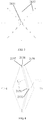


Classifications
-
- A—HUMAN NECESSITIES
- A61—MEDICAL OR VETERINARY SCIENCE; HYGIENE
- A61B—DIAGNOSIS; SURGERY; IDENTIFICATION
- A61B17/00—Surgical instruments, devices or methods
- A61B17/0057—Implements for plugging an opening in the wall of a hollow or tubular organ, e.g. for sealing a vessel puncture or closing a cardiac septal defect
-
- A—HUMAN NECESSITIES
- A61—MEDICAL OR VETERINARY SCIENCE; HYGIENE
- A61B—DIAGNOSIS; SURGERY; IDENTIFICATION
- A61B17/00—Surgical instruments, devices or methods
- A61B17/12—Surgical instruments, devices or methods for ligaturing or otherwise compressing tubular parts of the body, e.g. blood vessels or umbilical cord
-
- A—HUMAN NECESSITIES
- A61—MEDICAL OR VETERINARY SCIENCE; HYGIENE
- A61B—DIAGNOSIS; SURGERY; IDENTIFICATION
- A61B17/00—Surgical instruments, devices or methods
- A61B17/12—Surgical instruments, devices or methods for ligaturing or otherwise compressing tubular parts of the body, e.g. blood vessels or umbilical cord
- A61B17/12022—Occluding by internal devices, e.g. balloons or releasable wires
- A61B17/12027—Type of occlusion
- A61B17/12031—Type of occlusion complete occlusion
-
- A—HUMAN NECESSITIES
- A61—MEDICAL OR VETERINARY SCIENCE; HYGIENE
- A61B—DIAGNOSIS; SURGERY; IDENTIFICATION
- A61B17/00—Surgical instruments, devices or methods
- A61B17/12—Surgical instruments, devices or methods for ligaturing or otherwise compressing tubular parts of the body, e.g. blood vessels or umbilical cord
- A61B17/12022—Occluding by internal devices, e.g. balloons or releasable wires
- A61B17/12099—Occluding by internal devices, e.g. balloons or releasable wires characterised by the location of the occluder
- A61B17/12122—Occluding by internal devices, e.g. balloons or releasable wires characterised by the location of the occluder within the heart
-
- A—HUMAN NECESSITIES
- A61—MEDICAL OR VETERINARY SCIENCE; HYGIENE
- A61B—DIAGNOSIS; SURGERY; IDENTIFICATION
- A61B17/00—Surgical instruments, devices or methods
- A61B17/12—Surgical instruments, devices or methods for ligaturing or otherwise compressing tubular parts of the body, e.g. blood vessels or umbilical cord
- A61B17/12022—Occluding by internal devices, e.g. balloons or releasable wires
- A61B17/12131—Occluding by internal devices, e.g. balloons or releasable wires characterised by the type of occluding device
- A61B17/1214—Coils or wires
- A61B17/12145—Coils or wires having a pre-set deployed three-dimensional shape
-
- A—HUMAN NECESSITIES
- A61—MEDICAL OR VETERINARY SCIENCE; HYGIENE
- A61B—DIAGNOSIS; SURGERY; IDENTIFICATION
- A61B17/00—Surgical instruments, devices or methods
- A61B17/12—Surgical instruments, devices or methods for ligaturing or otherwise compressing tubular parts of the body, e.g. blood vessels or umbilical cord
- A61B17/12022—Occluding by internal devices, e.g. balloons or releasable wires
- A61B17/12131—Occluding by internal devices, e.g. balloons or releasable wires characterised by the type of occluding device
- A61B17/1214—Coils or wires
- A61B17/1215—Coils or wires comprising additional materials, e.g. thrombogenic, having filaments, having fibers, being coated
-
- A—HUMAN NECESSITIES
- A61—MEDICAL OR VETERINARY SCIENCE; HYGIENE
- A61F—FILTERS IMPLANTABLE INTO BLOOD VESSELS; PROSTHESES; DEVICES PROVIDING PATENCY TO, OR PREVENTING COLLAPSING OF, TUBULAR STRUCTURES OF THE BODY, e.g. STENTS; ORTHOPAEDIC, NURSING OR CONTRACEPTIVE DEVICES; FOMENTATION; TREATMENT OR PROTECTION OF EYES OR EARS; BANDAGES, DRESSINGS OR ABSORBENT PADS; FIRST-AID KITS
- A61F2/00—Filters implantable into blood vessels; Prostheses, i.e. artificial substitutes or replacements for parts of the body; Appliances for connecting them with the body; Devices providing patency to, or preventing collapsing of, tubular structures of the body, e.g. stents
- A61F2/02—Prostheses implantable into the body
- A61F2/04—Hollow or tubular parts of organs, e.g. bladders, tracheae, bronchi or bile ducts
-
- A—HUMAN NECESSITIES
- A61—MEDICAL OR VETERINARY SCIENCE; HYGIENE
- A61B—DIAGNOSIS; SURGERY; IDENTIFICATION
- A61B17/00—Surgical instruments, devices or methods
- A61B17/0057—Implements for plugging an opening in the wall of a hollow or tubular organ, e.g. for sealing a vessel puncture or closing a cardiac septal defect
- A61B2017/00575—Implements for plugging an opening in the wall of a hollow or tubular organ, e.g. for sealing a vessel puncture or closing a cardiac septal defect for closure at remote site, e.g. closing atrial septum defects
- A61B2017/00592—Elastic or resilient implements
-
- A—HUMAN NECESSITIES
- A61—MEDICAL OR VETERINARY SCIENCE; HYGIENE
- A61B—DIAGNOSIS; SURGERY; IDENTIFICATION
- A61B17/00—Surgical instruments, devices or methods
- A61B17/0057—Implements for plugging an opening in the wall of a hollow or tubular organ, e.g. for sealing a vessel puncture or closing a cardiac septal defect
- A61B2017/00575—Implements for plugging an opening in the wall of a hollow or tubular organ, e.g. for sealing a vessel puncture or closing a cardiac septal defect for closure at remote site, e.g. closing atrial septum defects
- A61B2017/00597—Implements comprising a membrane
-
- A—HUMAN NECESSITIES
- A61—MEDICAL OR VETERINARY SCIENCE; HYGIENE
- A61B—DIAGNOSIS; SURGERY; IDENTIFICATION
- A61B17/00—Surgical instruments, devices or methods
- A61B17/0057—Implements for plugging an opening in the wall of a hollow or tubular organ, e.g. for sealing a vessel puncture or closing a cardiac septal defect
- A61B2017/00575—Implements for plugging an opening in the wall of a hollow or tubular organ, e.g. for sealing a vessel puncture or closing a cardiac septal defect for closure at remote site, e.g. closing atrial septum defects
- A61B2017/00632—Occluding a cavity, i.e. closing a blind opening
-
- A—HUMAN NECESSITIES
- A61—MEDICAL OR VETERINARY SCIENCE; HYGIENE
- A61B—DIAGNOSIS; SURGERY; IDENTIFICATION
- A61B17/00—Surgical instruments, devices or methods
- A61B2017/00743—Type of operation; Specification of treatment sites
- A61B2017/00796—Breast surgery
-
- A—HUMAN NECESSITIES
- A61—MEDICAL OR VETERINARY SCIENCE; HYGIENE
- A61B—DIAGNOSIS; SURGERY; IDENTIFICATION
- A61B17/00—Surgical instruments, devices or methods
- A61B2017/00831—Material properties
Definitions
- the present disclosure relates to a medical device, and more particularly relates to a left atrial appendage occluder.
- an occluder may be put into a left atrial appendage through a catheter intervention method to prevent a thrombus from forming in the left atrial appendage due to atrial fibrillation and avoid apoplexy caused by the thrombus going up to a brain, or prevent systematic embolism caused by the thrombus reaching other portions of a body through the body's blood circulation system.
- Such left atrial appendage occluders substantially include an integrated occluder and a split type occluder according to their structures.
- the split occluder generally includes a fixing frame and a sealing plate which are connected with each other; the fixing frame is disposed in a cavity of the left atrial appendage to fix the whole occluder; and the sealing plate seals an opening portion of the left atrial appendage to prevent blood flow from flowing into the cavity of the left atrial appendage.
- the fixing frame and sealing plate have a connection restriction, wherein one component will be pulled by the other component, and the two components may not deform independently.
- the fixing frame will pull the sealing plate when in a process of complying with a cavity structure of the left atrial appendage and its own movement of the left atrial appendage; and in the process, the sealing plate may not be fully fitted to an opening portion of the left atrial appendage and a blood flow channel will be formed between a left atrium and the left atrial appendage, so that an optimal sealing effect may not be achieved, and then the thrombus in the left atrial appendage flows out of the left atrial appendage, which will cause the apoplexy.
- a left atrial appendage occluder including a sealing plate and a fixing frame connected with the sealing plate, the sealing plate includes a proximal disk surface and a distal disk surface; the proximal disk surface includes a number of elastic proximal supporting rods arranged in a radiated manner in a radial direction; the distal disk surface includes a number of elastic distal supporting rods arranged in a radiated manner in the radial direction; and a hanging end of each proximal supporting rod is connected with a hanging end of one distal supporting rod adjacent to the proximal supporting rod.
- the proximal disk surface includes a proximal seal head; one end of each proximal supporting rod is connected with the proximal seal head, and the other end of the proximal supporting rod is radiated in the radial direction and is hanging;
- the distal disk surface includes a distal seal head; and one end of each distal supporting rod is connected with the distal seal head, and the other end of the distal supporting rod is radiated in the radial direction and is hanging.
- proximal seal head and the distal seal head are axially aligned; and a projection of each distal supporting rod in the proximal disk surface is basically overlapped with one proximal supporting rod connected with the distal supporting rod.
- the proximal seal head and all of the proximal supporting rods are formed by integrated or integratedly cutting, and/or the distal seal head and all of the distal supporting rods are formed by integratedly cutting, and/or the proximal supporting rods and the distal supporting rods connected with the proximal supporting rods are formed by integratedly bending of one rod body.
- a proximal connection included angle between the proximal seal head and one proximal supporting rod is an acute angle
- a distal connection included angle between the distal seal head and one distal supporting rod is an acute angle
- the proximal connection included angle between the proximal seal head and one proximal supporting rod is in a range from 15 degrees to 90 degrees or 60 degrees to 85 degrees
- the distal connection included angle between the distal seal head and one distal supporting rod is in a range from 15 degrees to 90 degrees or 60 degrees to 85 degrees.
- the distal supporting rod includes a distal connecting section and a distal hanging section; one end of each distal connecting section is connected with the distal seal head, and the other end of the distal connecting section is connected with one end of each distal hanging section; the other end of each distal hanging section is connected with the hanging end of one proximal supporting rod; and the distal hanging sections are basically perpendicular to the axial line of the distal seal head.
- the hardness of the distal connecting section is greater than that of the distal hanging section.
- the proximal supporting rod includes a proximal connecting section and a proximal hanging section; one end of each proximal connecting section is connected with the proximal seal head, and the other end of the proximal connecting section is connected with one end of each proximal hanging section; and the proximal hanging section of each proximal supporting rod is connected with one distal hanging section adjacent to the proximal hanging section.
- the hardness of the proximal connecting sections is greater than that of the proximal hanging sections.
- the proximal disk surface is basically parallel to the distal disk surface.
- the proximal supporting rod and the distal supporting rods connected with the corresponding proximal supporting rod are formed by bending one rod body, and the rod body is bent at the hanging end.
- the distal disk surface further includes a distal supporting structure with a number of grids; the distal supporting structure is radially deployed from the center of the distal disk surface along the radial direction; and the distal supporting rods are all connected with the distal supporting structure.
- the distal supporting structure includes a number of distal branches; the distal branches are connected with one another two by two to form the grids; and one end of each of part of the distal branches is gathered and connected at the center of the distal disk surface.
- the proximal disk surface further includes a proximal supporting structure with a number of grids; the proximal supporting structure is radially deployed from the center of the proximal disk surface along the radial direction; and the proximal supporting rods are all connected with the proximal supporting structure.
- the proximal supporting structure further includes proximal branches; the proximal branches are connected with one another two by two to form the grids; and one end of each of part of the proximal branches is gathered and connected at the center of the proximal disk surface.
- the sealing plate further includes a sealing film which covers at least one disk surface of the proximal disk surface and the distal disk surface.
- an outer circumferential edge of the sealing film extends out 1 mm to 15 mm in the radial direction relative to an outer circumferential edge of the disk surface covered by the sealing film.
- the radial deformability of the sealing plate is greater than that of the fixing frame and/or the axial deformability of the sealing plate is greater than that of the fixing frame.
- the fixing frame includes multiple supporting members; one end of each supporting member is gathered and connected at the center of the fixing frame, and the other end of the supporting member extends out in a radiated manner from the center of the fixing frame; and the multiple supporting members cooperate to form an umbrella-shaped structure.
- the supporting rods at the maximum-diameter portion of the sealing plate are relatively independent, the deformation of the maximum-diameter portion of the sealing plate may be increased to ensure that the outer edge of the sealing plate may adapt to various irregular opening portion shapes of left atrial appendages, and to achieve an optimal fitting and sealing effect.
- all the supporting rods of a framework may maintain a certain supporting force to resist a pulling force caused by its own movement of the left atrial appendage and a movement of the fixing frame, and to avoid long-term leakage, thereby reducing the risk of thrombosis and apoplexy.
- distal end For the purpose of making the description of a structure of a left atrial appendage occluder clearer, the present disclosure defines terms “distal end” and "proximal end”.
- the above-mentioned terms are common used in the field of interventional medical devices.
- distal end represents an end far away from an operator in a surgical process
- proximal end represents an end close to the operator in the surgical process.
- a left atrial appendage occluder of one embodiment of the present disclosure includes a sealing plate 21 and a fixing frame 12 connected with the sealing plate 21.
- the fixing frame 12 is located in a cavity of the left atrial appendage and is closely fitted to the cavity wall to prevent the left atrial appendage occluder from falling off from the left atrial appendage;
- the sealing plate 21 seals an opening portion of the left atrial appendage to prevent a thrombus formed in a cavity of a left atrium from flowing into the left atrium, and/or to prevent blood flow from flowing from the left atrium into the cavity of the left atrial appendage.
- the sealing plate 21 includes a framework 213 and a sealing film 212 arranged on the framework 213.
- the framework 213 is overall of an umbrella-shaped skeletal structure.
- the framework 213 includes a proximal disk surface 2134 and a distal disk surface 2135. After the left atrial appendage occluder is implanted into the left atrial appendage, the proximal disk surface 2134 faces to the left atrium, and the distal disk surface 2135 faces to a cavity of the left atrial appendage.
- the proximal disk surface 2134 includes a proximal seal head 2131 and multiple elastic proximal supporting rods 2137 radially arranged in a radial direction;
- the distal disk surface 2135 includes a distal seal head 2132 and multiple elastic distal supporting rods 2139 radially arranged in the radial direction; and a hanging end of each proximal supporting rod 2137 is connected with a hanging end of one distal supporting rod 2139 adjacent to the proximal supporting rod 2137.
- each proximal supporting rod 2137 is connected with the proximal seal head 2131, and the other end of the proximal supporting rod 2137 is radiated along the radial direction and then suspended; one end of each distal supporting rod 2139 is connected with the distal seal head 2132, and the other end of the distal supporting rod 2139 is radiated along the radial direction and then suspended.
- the proximal supporting rods 2137 and the distal supporting rods 2139 connected with the proximal supporting rods 2137 may be formed by bending one rod body 2138, and the rod body 2138 is bent at the hanging ends.
- the proximal supporting rods 2137 of the proximal disk surface 2134 and the distal supporting rods 2139 of the distal disk surface 2135 of the sealing plate 21 all have hanging ends, and near the hanging ends, adjacent proximal supporting rods 2137 and adjacent distal supporting rods 2139 are relatively independent of each other, so that it is possible to increase the deformation of the sealing plate 21 here to ensure that the outer edge of the sealing plate 21 adapts to various irregular opening shapes of left atrial appendages to achieve an optimal fitting and sealing effect.
- the sealing plate 21 has two disk surfaces, namely the proximal disk surface 2134 and the distal disk surface 2135. An interval is reserved between the two disk surfaces, but the two disk surfaces are still connected at the hanging ends. Preferably, except for the connection at the hanging ends, no other mutual connections are formed between the two disk surfaces.
- all the proximal supporting rods 2137 and the distal supporting rods 2139 may maintain a certain amount of supporting force; when any one of the two disk surfaces is pulled, as the interval between the two disk surfaces provides a certain buffer effect, the pulling action on this disk surface may not directly act on the other disk surface, and the connected hanging ends further allow the non-pulled disk surface to play a role of pulling back the pulled disk surface to reduce a deformation amplitude of the pulled disk surface, thereby reducing poor sealing caused by disk surface deformation, and improving the occluding reliability of the left atrial appendage occluder.
- the distal disk surface 2135 when the proximal disk surface 2134 deforms under the pull of a delivery apparatus during delivery or releasing, the distal disk surface 2135 deforms very little and is essentially not affected by the pulling action due to the interval between the two disk surfaces, thereby guaranteeing the sealing effect; on the other hand, as the hanging ends of the two disk surfaces are connected, the distal disk surface 2135 may play a certain role of pulling back the proximal disk surface 2134 to avoid the position of the left atrial appendage occluder changing which will result in sealing failure, and even to avoid the left atrial appendage occluder falling off from the cavity of the left atrial appendage, due to an extremely large deformation of the proximal disk surface 2134 under the pull.
- the proximal disk surface 2134 basically may not be subjected to this pulling action, thus ensuring that the sealing plate still may be fitted to a tissue wall and maintain a sealing shape to guarantee the occluding effect; in addition, the proximal disk surface 2134 would further pull back the distal disk surface 2135 to a certain extent, to resist the pulling force caused by its own movement of the left atrial appendage and a movement of the fixing frame, and to avoid long-term leakage as far as possible, and to prevent the left atrial appendage occluder from falling into the cavity of the left atrial appendage.
- the framework 213 of the sealing plate 21 is designed to be an umbrella-shaped skeleton, so that the structure is light in weight, and the metal content of the framework 213 may be reduced, and the amount of metal ions released into blood is decreased in a long term.
- the distal supporting rod 2139 includes a distal connecting section 2139a and a distal hanging section 2139b; one end of each distal connecting section 2139a is connected with the distal seal head 2132, and the other end of the distal connecting section 2139a is connected with one end of each distal hanging section 2139b; and the other end of each distal hanging section 2139b is connected with the hanging end of one proximal supporting rod 2137.
- the proximal supporting rod 2137 includes proximal connecting section 2137a and a proximal hanging section 2137b; one end of each proximal connecting section 2137a is connected with the proximal seal head 2131, and the other end of the proximal connecting section 2137a is connected with one end of each proximal hanging section 2137b; and the proximal hanging section 2137b of the proximal supporting rod 2137 is connected with the distal hanging section2139b of the distal supporting rod 2139.
- the rod body 2138 is located between the proximal disk surface 2134 and the distal disk surface 2135 to space the proximal disk surface 2134 from the distal disk surface 2135 to form an interval between the two disk surfaces, so that the sealing plate 21 is of a two-layer structure.
- the proximal seal head 2131 may be located in the center region of the proximal disk surface 2134.
- the distal seal head 2132 may be located in the center region of the distal disk surface 2135.
- the proximal seal head 2131 and the distal seal head 2132 are axially aligned. Further, the axial line of the distal seal head 2132 and the axial line of the proximal seal head 2131 are both overlapped with the axial line 2136 of the framework 213.
- the proximal seal head 2131 and the distal seal head 2132 are arranged on the axial line 2136 of the framework 213 in a spaced manner.
- a projection of each distal supporting rod 2139 on the proximal disk surface 2134 is basically overlapped with one proximal supporting rod 2137 connected with this distal supporting rod 2139.
- the distal hanging section 2139b is substantially perpendicular to the axial line of the distal seal head 2132.
- the proximal hanging section 2137b is substantially perpendicular to the axial line of the proximal seal head 2131.
- the proximal disk surface 2134 is substantially parallel to the distal disk surface 2135. It can be specifically understood that the proximal connecting sections 2137a of the proximal supporting rods 2137 are parallel to the distal connecting sections 2139a of the correspondingly connected distal supporting rods 2139, and the proximal hanging sections 2137b of the proximal supporting rods 2137 are parallel to the distal hanging sections 2139b of the correspondingly connected distal supporting rods 2139.
- an included angle C between the proximal seal head 2131 and one proximal supporting rod 2137 is an acute angle
- an included angle between the distal seal head 2132 and one distal supporting rod 2139 is an acute angle
- the included angle C between the proximal supporting rod 2137 and the proximal seal head 2131 is 15 degrees to 90 degrees, and preferably 60 degrees to 85 degrees.
- proximal disk surface 2134 and the distal disk surface 2135 are formed a structure similar to a conical surface; the proximal seal head 2131 is located inside the structure, and the distal seal head 2132 is located at the vertex angle of the structure; and therefore, after the left atrial appendage occluder is implanted into the left atrial appendage, the sealing plate 21 may be better fitted to the opening portion of the left atrial appendage, and the distal disk surface 2135 may be fitted to the cavity wall, which is located at the opening portion of the left atrial appendage, of the left atrium.
- the hardness of the proximal hanging sections 2137b of the proximal supporting rods 2137 is greater than that of the distal hanging sections 2139b of the distal supporting rods 2139.
- distal hanging sections 2139b with lower hardness may reduce friction between the sealing plate 21 and the cavity wall, which is near to the opening portion of the left atrial appendage, of the left atrium, thereby avoiding a formation of hydropericardium or cardiac tamponade as much as possible.
- the hardness of the distal connecting sections 2139a may be greater than that of the distal hanging sections 2139b in the distal disk surface 2135, so that it is able to reduce the friction between the distal hanging sections 2139b and a tissue wall to which the distal hanging sections 2139b are attached, and the distal connecting sections 2139a with the greater hardness ensure that the occluding shape of the disk surface is not liable to deform under the pull of the disk surface.
- the hardness of the proximal connecting sections 2137a also may be greater than that of the proximal hanging sections 2137b in the proximal disk surface 2134.
- At least two proximal supporting rods 2137 are provided, thereby ensuring that there are sufficient contact pivots and area between the framework 213 and the cavity wall at the opening portion of the left atrial appendage and guaranteeing a stable sealing effect.
- proximal seal head 2131 and all the proximal supporting rods 2137 are integrated- or integratedly-formed by cutting.
- the distal seal head 2132 and all the distal supporting rods 2139 are integratedly-formed by cutting.
- the whole framework 213 may be formed by cutting a metal tube into a preset pattern and then shaped by a thermal treatment.
- the framework 213 may be formed by cutting a metal (preferably nickel-titanium material) tube with a diameter of 0.3 mm to 5 mm into a certain pattern, and then shaped by thermal treatment shaping.
- the proximal seal head 2131 and the proximal supporting rods 2137 are integrated, as well as the distal seal head 2132 and the distal supporting rods 2139.
- the framework 213 also may be formed by carrying out thermal treatment on multiple metal wires and then fixedly connecting the metal wires.
- the metal wires are preferably made of a nickel-titanium material.
- two ends of multiple metal wires with the diameter of 0.05 mm to 0.8 mm or two ends of multiple flat metal wires with the sectional area of 0.03 mm x 0.8 mm are fixed by welding, riveting, adhering, or other manners, as desired, to form the proximal seal head 2131 and the distal seal head 2132, and then the metal wires are shaped by a thermal treatment to obtain the framework 213 with corresponding shape.
- FIG. 5 and Figure 6 illustrate a framework 214 provided by another embodiment.
- This framework 214 also includes a proximal disk surface 2144, a distal disk surface 2145 and other structures.
- the proximal disk surface 2144 includes a proximal seal head 2141 and proximal supporting rods 2147;
- the distal disk surface 2145 includes a distal seal head 2142 and distal supporting rods 2149.
- the difference from the framework 213 in the above embodiment is that the distal disk surface 2145 in this embodiment also includes a distal supporting structure 2148 with multiple grids; the distal supporting structure 2148 radiates from the center of the distal disk surface 2145 along a radial direction; and the multiple distal supporting rods 2149 are all connected with the distal supporting structure 2148.
- the distal supporting structure 2148 includes multiple distal branches; and the multiple distal branches are connected with one another two by two to form the multiple grids, wherein one end of each of part of the multiple distal branches is gathered and connected at the center of the distal disk surface 2145.
- the proximal disk surface 2144 also includes a proximal supporting structure 2146 with multiple grids; the proximal supporting structure 2146 radiates from the center of the proximal disk surface 2144 along the radial direction; and the multiple proximal supporting rods 2147 are all connected with the proximal supporting structure 2146.
- the proximal supporting structure 2146 includes multiple proximal branches; and the multiple proximal branches are connected with one another in a two by two manner to form the multiple grids, wherein one end of each of part of the multiple proximal branches is gathered and connected at the center of the proximal disk surface 2144.
- the disk surface of the proximal disk surface 2144 and the distal disk surface 2145 has the above-mentioned supporting structure.
- the proximal supporting structure 2146 and the distal supporting structure 2148 are located in the center region of the framework 214, and are both separated from the other in a disconnected state, respectively, to maintain relative independence, so that strength of the supporting force of the sealing plate 21 is enhanced at the center region, where the supporting structure is located, to ensure that the sealing plate 21 has a sufficient supporting force and will not be pulled by the fixing frame 12 into the left atrial appendage.
- the proximal supporting rods 2137 and the distal supporting rods 2139 still may be well fitted to the irregular shape of the opening portion of the left atrial appendage at the hanging ends, thereby achieving an optimal sealing effect.
- the sealing film 212 may be a single-layer film covering at least one disk surface of the framework 213, specifically covering the proximal disk surface 2134 and/or the distal disk surface 2135 of the framework 213.
- the size of the sealing film 212 allows it to cover the whole proximal disk surface 2134 or is slightly larger than that of the proximal disk surface 2134, for example, the sealing film 212 extends out 1 mm to 15 mm in the radial direction relative to the outer circumferential edge of the proximal disk surface 2134, and the radial extending portion may be impending freely or extend towards the distal disk surface 2135 to cover it.
- the size of the sealing film 212 allows it to cover the whole distal disk surface 2135 or is slightly larger than that of the distal disk surface 2135.
- the sealing film 212 extends out 1 mm to 15 mm in the radial direction relative to the outer circumferential edge of the distal disk surface 2135, and the radial extending portion may be impending freely or extend towards the proximal disk surface 2134 to cover it.
- the sealing film 212 is generally made of a macromolecular material such as PET (polyethylene terephthalate), or PTFE (polytetrafluoroethylene), or a silica gel material, and also other thin film materials with biocompatibility and physical property which meet the requirements, as desired.
- a fixed connection between the sealing film 212 and the framework 213 may be realized by suturing, adhering or hot melting.
- the sealing film 212 is arranged on the sealing plate 21, so that the sealing film 212 is a portion, which directly contacts with a tissue at the opening portion of the left atrial appendage, of the sealing plate 21, thereby reducing abrasion between a metal material and the tissue at the opening portion, lowering the risk of hydropericardium or cardiac tamponade caused by tissue abrasion, and promoting endothelialization at the junction between the sealing plate 21 and the tissue to enhance the sealing effect.
- the whole framework 213 is covered by the sealing film 212, so that the amount of metal ions released by the framework 213 entering the blood and the tissue may be reduced, to reduce a risk of inflammation.
- the fixing frame 12 includes multiple supporting members 122; ends of the multiple supporting members 122 are connected together. For example, these ends may be fixedly connected by welding or riveting, and the other end of each of the multiple supporting members 122 extends out in a radiated manner; the multiple supporting members 122 cooperate to form an umbrella-shaped structure; and each supporting member 122 includes a hanging supporting section 123.
- the fixing frame may be made by cutting, for example, the fixing frame may be obtained by cutting a metal tube; the metal tube may be made of a shape memory material, for example a nickel-titanium alloy.
- anchor bars 124 also may be formed on the hanging supporting sections 123; the anchor bars 124 are inserted into the cavity wall of the left atrial appendage to connect the fixing frame with the cavity wall. After the left atrial appendage occluder, implanted into a human body, is released and unfolded, the fixing frame 12 is placed into the cavity of the left atrial appendage and attached to the cavity wall of the left atrial appendage; and the sealing plate 21 covers the opening of the left atrial appendage.
- the sealing plate 21 is connected with a proximal end 121 of the fixing frame 12 through the distal seal head 2132 of the framework 213, and the connection between the sealing plate 21 and the fixing frame 12 may be realized in a welding, riveting, adhering or interference fit way.
- the left atrial appendage occluder also may include a connection member for connecting the sealing plate 21 with the fixing frame 12.
- the connection member is flexible and elastic. One side of the connection member is connected with the distal seal head 2132, and the other side of the connection member is connected with the proximal end 121 of the fixing frame 12. This connection may be realized in a welding, riveting, adhering or interference fit way.
- connection member may change its length to adjust a distance between the sealing plate 21 and the fixing frame 12 under the action of an external force, for example under the pulling action of the sealing plate 21 and/or the fixing frame 12, by virtue of its flexibility and elasticity, and also may adjust an angle between the sealing plate 21 and the fixing frame 12. Therefore, the left atrial appendage occluder provided by the present disclosure may meet implantation requirements of left atrial appendages in different shapes such as, for example, a chicken wing shape and a conical shape.
- the radial deformability of the sealing plate 21 of the left atrial appendage occluder is greater than that of the fixing frame 12 and/or the axial deformability of the sealing plate 21 is greater than that of the fixing frame 12.
- a radial length variation of the sealing plate 21 is greater than that of the fixing frame 12; or under the action of the same radial force, a radial length change rate of the sealing plate 21 is greater than that of the fixing frame 12; or under the action of the same axial force, a displacement of the sealing plate 21 along an axial force direction is greater than that of the fixing frame along the axial force direction.
- Radial length changes of the fixing frame and the sealing plate under the action of the same radial force may be respectively tested by a flat plate method.
- the left atrial appendage occluder may be tested by the flat plate method.
- radial acting forces F are applied to the fixing frame 12 by two parallel flat plates 61 and 62.
- the parallel flat plates 61 and 62 are respectively placed on two opposite sides of a diameter of the fixing frame 12, and two radial acting forces F with the same size and opposite directions are respectively applied to the flat plates 61 and 62 along the diameter.
- the diameter of the fixing frame 12 penetrates through and is perpendicular to a central axial line 140.
- the two parallel flat plates 61 and 62 maintain a mutually parallel state in the whole test process, namely the flat plates are parallel to the central axial line 140 all the time in the test process.
- any one of the flat plates at least covers a contour with maximum radius of the fixing frame 12, and preferably the flat plate covers the whole fixing frame 12 in a direction parallel to the central axial line 140.
- the radial lengths of portions, where the flat plates are loaded, of the fixing frame 12 are R1
- the radial length variation of the fixing frame 12 under the action of the radial forces F is a radial length difference obtained before and after radial compression, and may be expressed by AR1, so that the radial length change rate is ⁇ R1/R1.
- a thickness of the flat plates is at least 5 mm.
- the sealing plate 21 is tested by the flat plate test method as above, namely the same radial acting forces F, which refers to the same the size, direction and acting time, are adopted.
- the radial length variation ⁇ R2 or the radial length change rate ⁇ R2/R2 of the sealing plate 21 is tested; and at the moment, a contour with maximum radius of the sealing plate 21 is located at the edges of the double plates.
- the radial length variation ⁇ R2 of the sealing plate 21 of the left atrial appendage occluder according to the embodiment of the present disclosure is greater than the radial length variation ⁇ R1 of the fixing frame 12; or the radial length change rate ⁇ R2/R2 of the sealing plate 21 of the left atrial appendage occluder according to the embodiment of the present disclosure is greater than the radial length change rate ⁇ R1/R1 of the fixing frame 12.
- the left atrial appendage occluder After the left atrial appendage occluder is implanted into a human body, a situation where the implantation location may be improperly selected, may occur. For example, if the fixing frame extends too deep into the cavity of the left atrial appendage, an axial length of the occluder in the naturally unfolded state would be shorter than a relative distance between the fixing frame and the sealing plate after the implantation, which will lead to a mutual traction between the fixing frame and the sealing plate. Or, the implanted occluder would move together with the heart, but the implanted occluder and the heart have different amplitudes or directions of motion, which may lead to the mutual traction between the fixing frame and the sealing plate. Generally, the fixing plate and the sealing plate pull each other through the connection member.
- the fixing frame When the fixing frame is pulled by the sealing plate, as the fixing frame is fixed in the cavity of the left atrial appendage through a radial supporting force surrounding a circumferential region of the central axial line 140, the fixing frame is attached to the circumferential region of the cavity of the left atrial appendage to resist this pulling acting force. Therefore, the fixing frame will be radially deformed under the axial acting force and the fixing frame will separate from the cavity wall of the left atrial appendage if the pulling acting force is large enough, and then the left atrial appendage occluder would fall off, which will cause an implantation failure.
- the sealing plate When the sealing plate is pulled by the fixing frame, the sealing plate has the disk surface structure and is connected with the connection member through the disk surface, so that the axial pulling on the sealing plate would also lead to a radial deformation of the sealing plate.
- the fixing frame and the sealing plate pull each other, the one who is easily deformed in the radial direction will be pulled by the other one.
- the fixing frame would dominate the traction and pull the sealing plate to make the sealing plate deform towards the fixing frame direction (or towards the distal end).
- Such deformation enables the sealing plate to be closer to a left atrial wall at an opening of the left atrial appendage than that of the sealing plate in the naturally unfolded state, which enhances a sealing effect between the sealing plate and the opening of the left atrial appendage and avoids an interval between the sealing plate and the left atrial wall, so that it can prevent apoplexy or systematic embolism caused by blood flowing into the cavity of the left atrial appendage and a thrombus flowing into a left atrium through the interval.
- the fixing frame dominates the traction so that the fixing frame will not easily separate from the cavity wall of the left atrial appendage under the pull of the sealing plate, and the occluder will be better fixed in the left atrial appendage to avoid falling off from the left atrial appendage.
- the above flat plate method is only an example method, and not a limitation of the present disclosure.
- a person of ordinary skill in the art can adopt any other proper method, equivalent to the flat plate method, for testing.
- a test method that the radial acting force is evenly applied to a tested component in a circumferential direction may be utilized.
- three arc-shaped plates 63 may be uniformly disposed, in the same circumferential direction, on the contour with maximum radius of the tested component (the fixing frame or the sealing plate).
- radial acting forces F are simultaneously applied to the above arc-shaped plates 63 along a radial direction to test a variation or a change rate of a radial length R of the tested component.
- a thickness of the arc-shaped plates is at least 5 mm.
- the left atrial appendage occluder may be tested by a radial supporting force tester RX550-100 of the Machine Solution Inc (MSI) Company.
- the axial deformability of the tested component is expressed by testing an axial displacement (along the direction of the central axial line 140) of the tested component under an action of the same axial force.
- the above restriction is equidimensional restriction, that is to say, in the restriction process, the tested component does not elastically deform or deforms a little, which may be ignored; and in addition, the axial acting force is applied to a position, where no elastic deformation occurs, of the tested component.
- the same axial acting forces are applied to end portions, which are connected with the connection member, of the tested component, and the axial displacement of the tested component is used to express its own deformability
- the axial displacement of the component here refers to a position, where the axial acting force is applied, of the tested component, and the left atrial appendage meets the condition that the axial displacement of the fixing frame is less than that of the sealing plate.
- Detailed test methods will be described below according to the structure of the left atrial appendage occluder.
- the fixing frame and the sealing plate are independently tested, for example, only a single fixing frame or a single sealing plate is tested at each time.
- a clamping portion where the fixing frame 33 is clamped by an annular clamping member 71 along a circumferential direction, is the contour with maximum radius of the fixing frame 12.
- the annular clamping member 71 surrounds, and is perpendicular to, the central axial line 140.
- the radial size of the clamping portion of the fixing frame 12 is basically equal to that of a fixing frame 33 in the naturally unfolded state, so that the elastic deformation may be ignored.
- the axial displacement ⁇ O1 is used to express the deformation (or the deformability) of the fixing frame 12 in the first axial deformability test method, and the state of the clamping member 71 itself stays unchanged during the action of the axial acting force F1.
- the tested axial displacement represents the axial deformability of the fixing frame, which is under the pull of the sealing plate and the restricting action of the cavity of the left atrial appendage.
- the larger the axial displacement ⁇ O1 is, the easier it is for the fixing frame to be pulled and deformed.
- distal seal head 2132 of the sealing plate 21 is clamped by the clamping member 72; and the axial acting force F1, applied to the proximal seal head 2131 of the sealing plate 21 along the central axial line 140 and towards a direction away from the fixing frame 12, is equal to the text of the fixing frame 12.
- Measuring another axial displacement ⁇ O2 of a projection O2 of the proximal seal head 2131 on the central axial line 140 under the F1 is also performed.
- the axial displacement ⁇ O2 is used to express the axial deformation (or the deformability) of the sealing plate 21 in the first axial deformability test method.
- the tested axial displacement under the action of the axial acting force F1 represents the axial deformability of the sealing plate 21, which is under the pull of the fixing frame 12 and the restricting action of a wall of the opening portion of the left atrial appendage.
- the axial displacement ⁇ O1 of the fixing frame is less than the axial displacement ⁇ O2 of the sealing plate. It can be understood that when the fixing frame and the sealing plate pull each other, the one who has a larger axial displacement will be pulled by the other one.
- the fixing frame would dominate the traction and pull the sealing plate during the traction to make the sealing plate deform towards a direction of the fixing frame (or towards the distal end).
- Such deformation enables the sealing plate to be more close to the left atrial wall at the opening of the left atrial appendage than that of the sealing plate in the naturally unfolded state, which enhances a sealing effect between the sealing plate and the opening of the left atrial appendage and avoids an interval between the sealing plate and the left atrial wall, so that it can prevent blood from flowing into the cavity of the left atrial appendage and a thrombus from flowing into a left atrium through the interval.
- the fixing frame dominates the traction so that the fixing frame will not easily separate from the cavity wall of the left atrial appendage under the pull of the sealing plate, and the occluder will be better fixed in the left atrial appendage to avoid falling off of the left atrial appendage.
- a second axial deformability test method may be further adopted.
- a clamping portion where the fixing frame 33 is clamped by an annular clamping member 76 along a circumferential direction, has the contour with maximum radius of the fixing frame 12.
- the annular clamping member surrounds and is perpendicular to the central axial line 140.
- the radial size of the clamping portion of the fixing frame 12 is smaller than that of a fixing frame 12 in the naturally unfolded state.
- the clamping portion of the fixing frame 12 is compressed in the radial direction, for example, the maximum radial length after compressed is 80 percent of the maximum radial length before it is compressed.
- a radial force F0 may be applied to the annular clamping member 76 to compress the fixing frame 12 in the radial direction.
- An axial acting force F2 is applied to the end portion 120, where the fixing frame 12 is connected with the connection member, and the end portion 120 does not deform ender the axial acting force F2 which is along the central axial line 140 and towards the direction of the sealing plate 21.
- the axial displacement ⁇ O3 is used to express the deformation (or the deformability) of the fixing frame 12 in the second axial deformability test method.
- the tested axial displacement under the action of the axial acting force represents the deformability of the fixing frame 12, which is under the pull of the sealing plate 21 and the restricting action of the cavity of the left atrial appendage.
- the sealing plate 21 includes a distal seal head 2132; and the connection member is connected with the distal seal head 2132.
- an annular fixing member 77 abuts a disk surface, which is towards the fixing frame 12 and located at the maximum edge of the sealing plate 31.
- the axial acting force F2 along the central axial line 140 and towards a direction of the fixing frame 12, is applied to the distal seal head 2132.
- a position where the disk surface is abutted maintains unchanged along the direction of the central axial line 140 due to the annular fixing member 77, thereby testing a projection displacement ⁇ O4 of the distal seal head 2132 on the central axial line 140.
- Such deformation enables the sealing plate to be more close to the left atrial wall at the opening portion of the left atrial appendage than that of the sealing plate in the naturally unfolded state, which enhances a sealing effect between the sealing plate and the opening of the left atrial appendage and avoids an interval between the sealing plate and the left atrial wall, so that it can prevent blood from flowing into the cavity of the left atrial appendage and prevent a thrombus from flowing into a left atrium through the interval.
- the fixing frame dominates the traction so that the fixing frame will not easily separate from the cavity wall of the left atrial appendage under the pull of the sealing plate, and the occluder will be better fixed in the left atrial appendage to avoid falling off of the left atrial appendage.
Landscapes
- Health & Medical Sciences (AREA)
- Life Sciences & Earth Sciences (AREA)
- Surgery (AREA)
- Animal Behavior & Ethology (AREA)
- Veterinary Medicine (AREA)
- Public Health (AREA)
- Engineering & Computer Science (AREA)
- Biomedical Technology (AREA)
- Heart & Thoracic Surgery (AREA)
- General Health & Medical Sciences (AREA)
- Vascular Medicine (AREA)
- Molecular Biology (AREA)
- Medical Informatics (AREA)
- Nuclear Medicine, Radiotherapy & Molecular Imaging (AREA)
- Reproductive Health (AREA)
- Cardiology (AREA)
- Gastroenterology & Hepatology (AREA)
- Pulmonology (AREA)
- Oral & Maxillofacial Surgery (AREA)
- Transplantation (AREA)
- Surgical Instruments (AREA)
- Prostheses (AREA)
Abstract
Description
- The present disclosure relates to a medical device, and more particularly relates to a left atrial appendage occluder.
- At present, an occluder may be put into a left atrial appendage through a catheter intervention method to prevent a thrombus from forming in the left atrial appendage due to atrial fibrillation and avoid apoplexy caused by the thrombus going up to a brain, or prevent systematic embolism caused by the thrombus reaching other portions of a body through the body's blood circulation system. Such left atrial appendage occluders substantially include an integrated occluder and a split type occluder according to their structures. For example, the split occluder generally includes a fixing frame and a sealing plate which are connected with each other; the fixing frame is disposed in a cavity of the left atrial appendage to fix the whole occluder; and the sealing plate seals an opening portion of the left atrial appendage to prevent blood flow from flowing into the cavity of the left atrial appendage.
- For the split occluder of this type, its fixing frame and sealing plate have a connection restriction, wherein one component will be pulled by the other component, and the two components may not deform independently. For example, once the fixing frame is fixed in a cavity of the left atrial appendage, the fixing frame will pull the sealing plate when in a process of complying with a cavity structure of the left atrial appendage and its own movement of the left atrial appendage; and in the process, the sealing plate may not be fully fitted to an opening portion of the left atrial appendage and a blood flow channel will be formed between a left atrium and the left atrial appendage, so that an optimal sealing effect may not be achieved, and then the thrombus in the left atrial appendage flows out of the left atrial appendage, which will cause the apoplexy.
- In view of the above problems, it is necessary to provide a left atrial appendage occluder with better sealing effect and higher adaptability.
- A technical scheme adopted to solve the technical problems is as follows: a left atrial appendage occluder is provided, including a sealing plate and a fixing frame connected with the sealing plate, the sealing plate includes a proximal disk surface and a distal disk surface; the proximal disk surface includes a number of elastic proximal supporting rods arranged in a radiated manner in a radial direction; the distal disk surface includes a number of elastic distal supporting rods arranged in a radiated manner in the radial direction; and a hanging end of each proximal supporting rod is connected with a hanging end of one distal supporting rod adjacent to the proximal supporting rod.
- In one embodiment, the proximal disk surface includes a proximal seal head; one end of each proximal supporting rod is connected with the proximal seal head, and the other end of the proximal supporting rod is radiated in the radial direction and is hanging; the distal disk surface includes a distal seal head; and one end of each distal supporting rod is connected with the distal seal head, and the other end of the distal supporting rod is radiated in the radial direction and is hanging.
- In one embodiment, the proximal seal head and the distal seal head are axially aligned; and a projection of each distal supporting rod in the proximal disk surface is basically overlapped with one proximal supporting rod connected with the distal supporting rod.
- In one embodiment, the proximal seal head and all of the proximal supporting rods are formed by integrated or integratedly cutting, and/or the distal seal head and all of the distal supporting rods are formed by integratedly cutting, and/or the proximal supporting rods and the distal supporting rods connected with the proximal supporting rods are formed by integratedly bending of one rod body.
- In one embodiment, a proximal connection included angle between the proximal seal head and one proximal supporting rod is an acute angle, and a distal connection included angle between the distal seal head and one distal supporting rod is an acute angle.
- In one embodiment, the proximal connection included angle between the proximal seal head and one proximal supporting rod is in a range from 15 degrees to 90 degrees or 60 degrees to 85 degrees, and the distal connection included angle between the distal seal head and one distal supporting rod is in a range from 15 degrees to 90 degrees or 60 degrees to 85 degrees.
- In one embodiment, the distal supporting rod includes a distal connecting section and a distal hanging section; one end of each distal connecting section is connected with the distal seal head, and the other end of the distal connecting section is connected with one end of each distal hanging section; the other end of each distal hanging section is connected with the hanging end of one proximal supporting rod; and the distal hanging sections are basically perpendicular to the axial line of the distal seal head.
- In one embodiment, the hardness of the distal connecting section is greater than that of the distal hanging section.
- In one embodiment, the proximal supporting rod includes a proximal connecting section and a proximal hanging section; one end of each proximal connecting section is connected with the proximal seal head, and the other end of the proximal connecting section is connected with one end of each proximal hanging section; and the proximal hanging section of each proximal supporting rod is connected with one distal hanging section adjacent to the proximal hanging section.
- In one embodiment, the hardness of the proximal connecting sections is greater than that of the proximal hanging sections.
- In one embodiment, the proximal disk surface is basically parallel to the distal disk surface.
- In one embodiment, the proximal supporting rod and the distal supporting rods connected with the corresponding proximal supporting rod are formed by bending one rod body, and the rod body is bent at the hanging end.
- In one embodiment, the distal disk surface further includes a distal supporting structure with a number of grids; the distal supporting structure is radially deployed from the center of the distal disk surface along the radial direction; and the distal supporting rods are all connected with the distal supporting structure.
- In one embodiment, the distal supporting structure includes a number of distal branches; the distal branches are connected with one another two by two to form the grids; and one end of each of part of the distal branches is gathered and connected at the center of the distal disk surface.
- In one embodiment, the proximal disk surface further includes a proximal supporting structure with a number of grids; the proximal supporting structure is radially deployed from the center of the proximal disk surface along the radial direction; and the proximal supporting rods are all connected with the proximal supporting structure.
- In one embodiment, the proximal supporting structure further includes proximal branches; the proximal branches are connected with one another two by two to form the grids; and one end of each of part of the proximal branches is gathered and connected at the center of the proximal disk surface.
- In one embodiment, the sealing plate further includes a sealing film which covers at least one disk surface of the proximal disk surface and the distal disk surface.
- In one embodiment, an outer circumferential edge of the sealing film extends out 1 mm to 15 mm in the radial direction relative to an outer circumferential edge of the disk surface covered by the sealing film.
- In one embodiment, the radial deformability of the sealing plate is greater than that of the fixing frame and/or the axial deformability of the sealing plate is greater than that of the fixing frame.
- In one embodiment, under an action of a same radial force, a radial length variation of the sealing plate is greater than that of the fixing frame; or under an action of the same radial force, a radial length change rate of the sealing plate is greater than that of the fixing frame; or under the action of the same axial force, a displacement of the sealing plate along an axial force direction is greater than that of the fixing frame along the axial force direction.In one embodiment, the fixing frame includes multiple supporting members; one end of each supporting member is gathered and connected at the center of the fixing frame, and the other end of the supporting member extends out in a radiated manner from the center of the fixing frame; and the multiple supporting members cooperate to form an umbrella-shaped structure.
- In the left atrial appendage occluder of the present disclosure, the supporting rods at the maximum-diameter portion of the sealing plate are relatively independent, the deformation of the maximum-diameter portion of the sealing plate may be increased to ensure that the outer edge of the sealing plate may adapt to various irregular opening portion shapes of left atrial appendages, and to achieve an optimal fitting and sealing effect. In addition, all the supporting rods of a framework may maintain a certain supporting force to resist a pulling force caused by its own movement of the left atrial appendage and a movement of the fixing frame, and to avoid long-term leakage, thereby reducing the risk of thrombosis and apoplexy.
-
-
Figure 1 is a schematic diagram of a left atrial appendage occluder provided by one embodiment of the present disclosure; -
Figure 2 is a schematic diagram of a framework of a sealing plate of the left atrial appendage occluder inFigure 1 ; -
Figure 3 is a front view of the framework inFigure 2 ; -
Figure 4 is a side view of the framework as shown inFigure 2 ; -
Figure 5 is a schematic diagram of a framework of a sealing plate of a left atrial appendage occluder provided by another embodiment of the present disclosure; -
Figure 6 is a front view of the framework inFigure 5 ; -
Figure 7 is a schematic diagram of a sealing plate of a left atrial appendage occluder provided by another embodiment of the present disclosure; -
Figure 8 is a schematic diagram of a test method of the radial deformability of a fixing frame of the left atrial appendage occluder inFigure 1 ; -
Figure 9 is a schematic diagram of a test method of the radial deformability of a sealing plate of the left atrial appendage occluder inFigure 1 ; -
Figure 10 is a schematic diagram of another specific test method of the radial deformability of the sealing plate/fixing frame of the left atrial appendage occluder inFigure 1 ; -
Figure 11 is a schematic diagram of a first test method of the axial deformability of the fixing frame of the left atrial appendage occluder inFigure 1 ; -
Figure 12 is a schematic diagram of a first test method of the axial deformability of the sealing plate of the left atrial appendage occluder inFigure 1 ; -
Figure 13 is a schematic diagram of a second test method of the axial deformability of the fixing frame of the left atrial appendage occluder inFigure 1 ; -
Figure 14 is a schematic diagram of a second test method of the axial deformability of the sealing plate of the left atrial appendage occluder inFigure 1 . - For the purpose of making the description of a structure of a left atrial appendage occluder clearer, the present disclosure defines terms "distal end" and "proximal end". The above-mentioned terms are common used in the field of interventional medical devices. To be more specific, the "distal end" represents an end far away from an operator in a surgical process, and the "proximal end" represents an end close to the operator in the surgical process.
- As shown in
Figure 1 , a left atrial appendage occluder of one embodiment of the present disclosure includes asealing plate 21 and afixing frame 12 connected with thesealing plate 21. After the left atrial appendage occluder is implanted into a left atrial appendage, thefixing frame 12 is located in a cavity of the left atrial appendage and is closely fitted to the cavity wall to prevent the left atrial appendage occluder from falling off from the left atrial appendage; thesealing plate 21 seals an opening portion of the left atrial appendage to prevent a thrombus formed in a cavity of a left atrium from flowing into the left atrium, and/or to prevent blood flow from flowing from the left atrium into the cavity of the left atrial appendage. - The
sealing plate 21 includes aframework 213 and a sealingfilm 212 arranged on theframework 213. - With reference to
Figure 1, Figure 2 ,Figure 3 and Figure 4 at the same time, theframework 213 is overall of an umbrella-shaped skeletal structure. Theframework 213 includes aproximal disk surface 2134 and adistal disk surface 2135. After the left atrial appendage occluder is implanted into the left atrial appendage, theproximal disk surface 2134 faces to the left atrium, and thedistal disk surface 2135 faces to a cavity of the left atrial appendage. - The
proximal disk surface 2134 includes aproximal seal head 2131 and multiple elastic proximal supportingrods 2137 radially arranged in a radial direction; thedistal disk surface 2135 includes adistal seal head 2132 and multiple elastic distal supportingrods 2139 radially arranged in the radial direction; and a hanging end of each proximal supportingrod 2137 is connected with a hanging end of one distal supportingrod 2139 adjacent to the proximal supportingrod 2137. - To be more specific, one end of each proximal supporting
rod 2137 is connected with theproximal seal head 2131, and the other end of the proximal supportingrod 2137 is radiated along the radial direction and then suspended; one end of each distal supportingrod 2139 is connected with thedistal seal head 2132, and the other end of the distal supportingrod 2139 is radiated along the radial direction and then suspended. The proximal supportingrods 2137 and the distal supportingrods 2139 connected with the proximal supportingrods 2137 may be formed by bending onerod body 2138, and therod body 2138 is bent at the hanging ends. - In this present disclosure, the proximal supporting
rods 2137 of theproximal disk surface 2134 and the distal supportingrods 2139 of thedistal disk surface 2135 of thesealing plate 21 all have hanging ends, and near the hanging ends, adjacent proximal supportingrods 2137 and adjacent distal supportingrods 2139 are relatively independent of each other, so that it is possible to increase the deformation of thesealing plate 21 here to ensure that the outer edge of thesealing plate 21 adapts to various irregular opening shapes of left atrial appendages to achieve an optimal fitting and sealing effect. - In addition, the
sealing plate 21 has two disk surfaces, namely theproximal disk surface 2134 and thedistal disk surface 2135. An interval is reserved between the two disk surfaces, but the two disk surfaces are still connected at the hanging ends. Preferably, except for the connection at the hanging ends, no other mutual connections are formed between the two disk surfaces. As theframework 213 is of the umbrella-shaped skeletal structure, all the proximal supportingrods 2137 and the distal supportingrods 2139 may maintain a certain amount of supporting force; when any one of the two disk surfaces is pulled, as the interval between the two disk surfaces provides a certain buffer effect, the pulling action on this disk surface may not directly act on the other disk surface, and the connected hanging ends further allow the non-pulled disk surface to play a role of pulling back the pulled disk surface to reduce a deformation amplitude of the pulled disk surface, thereby reducing poor sealing caused by disk surface deformation, and improving the occluding reliability of the left atrial appendage occluder. - To be more specific, when the
proximal disk surface 2134 deforms under the pull of a delivery apparatus during delivery or releasing, thedistal disk surface 2135 deforms very little and is essentially not affected by the pulling action due to the interval between the two disk surfaces, thereby guaranteeing the sealing effect; on the other hand, as the hanging ends of the two disk surfaces are connected, thedistal disk surface 2135 may play a certain role of pulling back theproximal disk surface 2134 to avoid the position of the left atrial appendage occluder changing which will result in sealing failure, and even to avoid the left atrial appendage occluder falling off from the cavity of the left atrial appendage, due to an extremely large deformation of theproximal disk surface 2134 under the pull. For another example, if thedistal disk surface 2135 is pulled by the fixing frame to adapt to the shape of the cavity of the left atrial appendage after the implantation of the left atrial appendage occluder is completed, theproximal disk surface 2134 basically may not be subjected to this pulling action, thus ensuring that the sealing plate still may be fitted to a tissue wall and maintain a sealing shape to guarantee the occluding effect; in addition, theproximal disk surface 2134 would further pull back thedistal disk surface 2135 to a certain extent, to resist the pulling force caused by its own movement of the left atrial appendage and a movement of the fixing frame, and to avoid long-term leakage as far as possible, and to prevent the left atrial appendage occluder from falling into the cavity of the left atrial appendage. - In addition, the
framework 213 of the sealingplate 21 is designed to be an umbrella-shaped skeleton, so that the structure is light in weight, and the metal content of theframework 213 may be reduced, and the amount of metal ions released into blood is decreased in a long term. - As shown in
Figures 2 through 4 , the distal supportingrod 2139 includes a distal connectingsection 2139a and adistal hanging section 2139b; one end of each distal connectingsection 2139a is connected with thedistal seal head 2132, and the other end of the distal connectingsection 2139a is connected with one end of eachdistal hanging section 2139b; and the other end of eachdistal hanging section 2139b is connected with the hanging end of one proximal supportingrod 2137. - The proximal supporting
rod 2137 includes proximal connectingsection 2137a and aproximal hanging section 2137b; one end of each proximal connectingsection 2137a is connected with theproximal seal head 2131, and the other end of the proximal connectingsection 2137a is connected with one end of eachproximal hanging section 2137b; and theproximal hanging section 2137b of the proximal supportingrod 2137 is connected with the distal hanging section2139b of the distal supportingrod 2139. - The
rod body 2138 is located between theproximal disk surface 2134 and thedistal disk surface 2135 to space theproximal disk surface 2134 from thedistal disk surface 2135 to form an interval between the two disk surfaces, so that the sealingplate 21 is of a two-layer structure. Theproximal seal head 2131 may be located in the center region of theproximal disk surface 2134. Thedistal seal head 2132 may be located in the center region of thedistal disk surface 2135. - To be more specific, as shown in
Figure 3 and Figure 4 , in a naturally unfolded state, theproximal seal head 2131 and thedistal seal head 2132 are axially aligned. Further, the axial line of thedistal seal head 2132 and the axial line of theproximal seal head 2131 are both overlapped with theaxial line 2136 of theframework 213. Theproximal seal head 2131 and thedistal seal head 2132 are arranged on theaxial line 2136 of theframework 213 in a spaced manner. A projection of each distal supportingrod 2139 on theproximal disk surface 2134 is basically overlapped with one proximal supportingrod 2137 connected with this distal supportingrod 2139. Further, thedistal hanging section 2139b is substantially perpendicular to the axial line of thedistal seal head 2132. Theproximal hanging section 2137b is substantially perpendicular to the axial line of theproximal seal head 2131. Theproximal disk surface 2134 is substantially parallel to thedistal disk surface 2135. It can be specifically understood that the proximal connectingsections 2137a of the proximal supportingrods 2137 are parallel to the distal connectingsections 2139a of the correspondingly connected distal supportingrods 2139, and theproximal hanging sections 2137b of the proximal supportingrods 2137 are parallel to thedistal hanging sections 2139b of the correspondingly connected distal supportingrods 2139. It is stated above that one face of theframework 213 deforms when under stress, and the other face is affected little. Therefore, after the stress on theframework 213 disappears, the proximal supportingrods 2137 and the distal supportingrods 2139 return to a mutual-parallel naturally unfolded states. - In one embodiment, an included angle C between the
proximal seal head 2131 and oneproximal supporting rod 2137 is an acute angle, and an included angle between thedistal seal head 2132 and one distal supportingrod 2139 is an acute angle. Further, the included angle C between the proximal supportingrod 2137 and theproximal seal head 2131 is 15 degrees to 90 degrees, and preferably 60 degrees to 85 degrees. Such setting allows theproximal disk surface 2134 and thedistal disk surface 2135 to form a structure similar to a conical surface; theproximal seal head 2131 is located inside the structure, and thedistal seal head 2132 is located at the vertex angle of the structure; and therefore, after the left atrial appendage occluder is implanted into the left atrial appendage, the sealingplate 21 may be better fitted to the opening portion of the left atrial appendage, and thedistal disk surface 2135 may be fitted to the cavity wall, which is located at the opening portion of the left atrial appendage, of the left atrium. - In one embodiment, by way of material treatment, the hardness of the
proximal hanging sections 2137b of the proximal supportingrods 2137 is greater than that of thedistal hanging sections 2139b of the distal supportingrods 2139. As thedistal hanging sections 2139b are closer to the opening portion of the left atrial appendage than theproximal hanging sections 2137b,distal hanging sections 2139b with lower hardness may reduce friction between the sealingplate 21 and the cavity wall, which is near to the opening portion of the left atrial appendage, of the left atrium, thereby avoiding a formation of hydropericardium or cardiac tamponade as much as possible. Further, the hardness of the distal connectingsections 2139a may be greater than that of thedistal hanging sections 2139b in thedistal disk surface 2135, so that it is able to reduce the friction between thedistal hanging sections 2139b and a tissue wall to which thedistal hanging sections 2139b are attached, and the distal connectingsections 2139a with the greater hardness ensure that the occluding shape of the disk surface is not liable to deform under the pull of the disk surface. Similarly, the hardness of the proximal connectingsections 2137a also may be greater than that of theproximal hanging sections 2137b in theproximal disk surface 2134. - At least two proximal supporting
rods 2137, preferably 6 to 8 proximal supportingrods 2137, are provided, thereby ensuring that there are sufficient contact pivots and area between theframework 213 and the cavity wall at the opening portion of the left atrial appendage and guaranteeing a stable sealing effect. - In some embodiments, the
proximal seal head 2131 and all the proximal supportingrods 2137 are integrated- or integratedly-formed by cutting. - In some embodiments, the
distal seal head 2132 and all the distal supportingrods 2139 are integratedly-formed by cutting. - In some embodiments, the
whole framework 213 may be formed by cutting a metal tube into a preset pattern and then shaped by a thermal treatment. To be more specific, theframework 213 may be formed by cutting a metal (preferably nickel-titanium material) tube with a diameter of 0.3 mm to 5 mm into a certain pattern, and then shaped by thermal treatment shaping. Theproximal seal head 2131 and the proximal supportingrods 2137 are integrated, as well as thedistal seal head 2132 and the distal supportingrods 2139. In some other embodiments, theframework 213 also may be formed by carrying out thermal treatment on multiple metal wires and then fixedly connecting the metal wires. The metal wires are preferably made of a nickel-titanium material. For example, two ends of multiple metal wires with the diameter of 0.05 mm to 0.8 mm or two ends of multiple flat metal wires with the sectional area of 0.03 mm x 0.8 mm are fixed by welding, riveting, adhering, or other manners, as desired, to form theproximal seal head 2131 and thedistal seal head 2132, and then the metal wires are shaped by a thermal treatment to obtain theframework 213 with corresponding shape. -
Figure 5 and Figure 6 illustrate aframework 214 provided by another embodiment. Thisframework 214 also includes aproximal disk surface 2144, adistal disk surface 2145 and other structures. Theproximal disk surface 2144 includes aproximal seal head 2141 and proximal supportingrods 2147; thedistal disk surface 2145 includes adistal seal head 2142 and distal supportingrods 2149. The difference from theframework 213 in the above embodiment is that thedistal disk surface 2145 in this embodiment also includes adistal supporting structure 2148 with multiple grids; thedistal supporting structure 2148 radiates from the center of thedistal disk surface 2145 along a radial direction; and the multiple distal supportingrods 2149 are all connected with thedistal supporting structure 2148. - Further, the
distal supporting structure 2148 includes multiple distal branches; and the multiple distal branches are connected with one another two by two to form the multiple grids, wherein one end of each of part of the multiple distal branches is gathered and connected at the center of thedistal disk surface 2145. - Further, the
proximal disk surface 2144 also includes aproximal supporting structure 2146 with multiple grids; theproximal supporting structure 2146 radiates from the center of theproximal disk surface 2144 along the radial direction; and the multipleproximal supporting rods 2147 are all connected with theproximal supporting structure 2146. Theproximal supporting structure 2146 includes multiple proximal branches; and the multiple proximal branches are connected with one another in a two by two manner to form the multiple grids, wherein one end of each of part of the multiple proximal branches is gathered and connected at the center of theproximal disk surface 2144. - It should be understood that at least one of the disk surface of the
proximal disk surface 2144 and thedistal disk surface 2145 has the above-mentioned supporting structure. In addition, theproximal supporting structure 2146 and thedistal supporting structure 2148 are located in the center region of theframework 214, and are both separated from the other in a disconnected state, respectively, to maintain relative independence, so that strength of the supporting force of the sealingplate 21 is enhanced at the center region, where the supporting structure is located, to ensure that the sealingplate 21 has a sufficient supporting force and will not be pulled by the fixingframe 12 into the left atrial appendage. On the other hand, the proximal supportingrods 2137 and the distal supportingrods 2139 still may be well fitted to the irregular shape of the opening portion of the left atrial appendage at the hanging ends, thereby achieving an optimal sealing effect. - As shown in
Figure 1 andFigure 7 , the sealingfilm 212 may be a single-layer film covering at least one disk surface of theframework 213, specifically covering theproximal disk surface 2134 and/or thedistal disk surface 2135 of theframework 213. When theproximal disk surface 2134 is covered, the size of the sealingfilm 212 allows it to cover the wholeproximal disk surface 2134 or is slightly larger than that of theproximal disk surface 2134, for example, the sealingfilm 212 extends out 1 mm to 15 mm in the radial direction relative to the outer circumferential edge of theproximal disk surface 2134, and the radial extending portion may be impending freely or extend towards thedistal disk surface 2135 to cover it. When thedistal disk surface 2135 is covered, the size of the sealingfilm 212 allows it to cover the wholedistal disk surface 2135 or is slightly larger than that of thedistal disk surface 2135. For example, the sealingfilm 212 extends out 1 mm to 15 mm in the radial direction relative to the outer circumferential edge of thedistal disk surface 2135, and the radial extending portion may be impending freely or extend towards theproximal disk surface 2134 to cover it. - The sealing
film 212 is generally made of a macromolecular material such as PET (polyethylene terephthalate), or PTFE (polytetrafluoroethylene), or a silica gel material, and also other thin film materials with biocompatibility and physical property which meet the requirements, as desired. A fixed connection between the sealingfilm 212 and theframework 213 may be realized by suturing, adhering or hot melting. - The sealing
film 212 is arranged on the sealingplate 21, so that the sealingfilm 212 is a portion, which directly contacts with a tissue at the opening portion of the left atrial appendage, of the sealingplate 21, thereby reducing abrasion between a metal material and the tissue at the opening portion, lowering the risk of hydropericardium or cardiac tamponade caused by tissue abrasion, and promoting endothelialization at the junction between the sealingplate 21 and the tissue to enhance the sealing effect. In addition, thewhole framework 213 is covered by the sealingfilm 212, so that the amount of metal ions released by theframework 213 entering the blood and the tissue may be reduced, to reduce a risk of inflammation. - As shown in
Figure 1 , the fixingframe 12 includes multiple supportingmembers 122; ends of the multiple supportingmembers 122 are connected together. For example, these ends may be fixedly connected by welding or riveting, and the other end of each of the multiple supportingmembers 122 extends out in a radiated manner; the multiple supportingmembers 122 cooperate to form an umbrella-shaped structure; and each supportingmember 122 includes ahanging supporting section 123. The fixing frame may be made by cutting, for example, the fixing frame may be obtained by cutting a metal tube; the metal tube may be made of a shape memory material, for example a nickel-titanium alloy. In some embodiments, anchor bars 124 also may be formed on thehanging supporting sections 123; the anchor bars 124 are inserted into the cavity wall of the left atrial appendage to connect the fixing frame with the cavity wall. After the left atrial appendage occluder, implanted into a human body, is released and unfolded, the fixingframe 12 is placed into the cavity of the left atrial appendage and attached to the cavity wall of the left atrial appendage; and the sealingplate 21 covers the opening of the left atrial appendage. - The sealing
plate 21 is connected with aproximal end 121 of the fixingframe 12 through thedistal seal head 2132 of theframework 213, and the connection between the sealingplate 21 and the fixingframe 12 may be realized in a welding, riveting, adhering or interference fit way. - Further, in some embodiments, the left atrial appendage occluder also may include a connection member for connecting the sealing
plate 21 with the fixingframe 12. The connection member is flexible and elastic. One side of the connection member is connected with thedistal seal head 2132, and the other side of the connection member is connected with theproximal end 121 of the fixingframe 12. This connection may be realized in a welding, riveting, adhering or interference fit way. - The connection member may change its length to adjust a distance between the sealing
plate 21 and the fixingframe 12 under the action of an external force, for example under the pulling action of the sealingplate 21 and/or the fixingframe 12, by virtue of its flexibility and elasticity, and also may adjust an angle between the sealingplate 21 and the fixingframe 12. Therefore, the left atrial appendage occluder provided by the present disclosure may meet implantation requirements of left atrial appendages in different shapes such as, for example, a chicken wing shape and a conical shape. - Further, the radial deformability of the sealing
plate 21 of the left atrial appendage occluder is greater than that of the fixingframe 12 and/or the axial deformability of the sealingplate 21 is greater than that of the fixingframe 12. To be more specific, under the action of the same radial force, a radial length variation of the sealingplate 21 is greater than that of the fixingframe 12; or under the action of the same radial force, a radial length change rate of the sealingplate 21 is greater than that of the fixingframe 12; or under the action of the same axial force, a displacement of the sealingplate 21 along an axial force direction is greater than that of the fixing frame along the axial force direction. - Radial length changes of the fixing frame and the sealing plate under the action of the same radial force may be respectively tested by a flat plate method. For example, with reference to
Figure 8 and Figure 9 , the left atrial appendage occluder may be tested by the flat plate method. - With reference to
Figure 8 , first, on the premise that the sealingplate 21 maintains a freely unfolded state, radial acting forces F are applied to the fixingframe 12 by two parallelflat plates flat plates frame 12, and two radial acting forces F with the same size and opposite directions are respectively applied to theflat plates frame 12 penetrates through and is perpendicular to a centralaxial line 140. The two parallelflat plates axial line 140 all the time in the test process. And any one of the flat plates at least covers a contour with maximum radius of the fixingframe 12, and preferably the flat plate covers thewhole fixing frame 12 in a direction parallel to the centralaxial line 140. In the naturally unfolded state, the radial lengths of portions, where the flat plates are loaded, of the fixingframe 12 are R1, the radial length variation of the fixingframe 12, under the action of the radial forces F, is a radial length difference obtained before and after radial compression, and may be expressed by AR1, so that the radial length change rate is ΔR1/R1. In order to guarantee that each of the flat plates itself is not deformed in a radial force applying process, and the radial forces can be evenly applied to all portions of the flat plates, and a thickness of the flat plates is at least 5 mm. - With reference to
Figure 9 , the sealingplate 21 is tested by the flat plate test method as above, namely the same radial acting forces F, which refers to the same the size, direction and acting time, are adopted. On the premise that the sealingplate 21 is naturally unfolded, the radial length variation ΔR2 or the radial length change rate ΔR2/R2 of the sealingplate 21 is tested; and at the moment, a contour with maximum radius of the sealingplate 21 is located at the edges of the double plates. Based on the above test condition, under the action of the same radial force, the radial length variation ΔR2 of the sealingplate 21 of the left atrial appendage occluder according to the embodiment of the present disclosure is greater than the radial length variation ΔR1 of the fixingframe 12; or the radial length change rate ΔR2/R2 of the sealingplate 21 of the left atrial appendage occluder according to the embodiment of the present disclosure is greater than the radial length change rate ΔR1/R1 of the fixingframe 12. - After the left atrial appendage occluder is implanted into a human body, a situation where the implantation location may be improperly selected, may occur. For example, if the fixing frame extends too deep into the cavity of the left atrial appendage, an axial length of the occluder in the naturally unfolded state would be shorter than a relative distance between the fixing frame and the sealing plate after the implantation, which will lead to a mutual traction between the fixing frame and the sealing plate. Or, the implanted occluder would move together with the heart, but the implanted occluder and the heart have different amplitudes or directions of motion, which may lead to the mutual traction between the fixing frame and the sealing plate. Generally, the fixing plate and the sealing plate pull each other through the connection member.
- When the fixing frame is pulled by the sealing plate, as the fixing frame is fixed in the cavity of the left atrial appendage through a radial supporting force surrounding a circumferential region of the central
axial line 140, the fixing frame is attached to the circumferential region of the cavity of the left atrial appendage to resist this pulling acting force. Therefore, the fixing frame will be radially deformed under the axial acting force and the fixing frame will separate from the cavity wall of the left atrial appendage if the pulling acting force is large enough, and then the left atrial appendage occluder would fall off, which will cause an implantation failure. When the sealing plate is pulled by the fixing frame, the sealing plate has the disk surface structure and is connected with the connection member through the disk surface, so that the axial pulling on the sealing plate would also lead to a radial deformation of the sealing plate. - Therefore, when the fixing frame and the sealing plate pull each other, the one who is easily deformed in the radial direction will be pulled by the other one. For example, under the same radial acting force, as the radial length variation of the fixing frame according to the embodiment of the present disclosure is less than that of the sealing plate, or the radial length change rate of the fixing frame according to the embodiment of the present disclosure is less than that of the sealing plate, in the mutual traction, the fixing frame would dominate the traction and pull the sealing plate to make the sealing plate deform towards the fixing frame direction (or towards the distal end). Such deformation enables the sealing plate to be closer to a left atrial wall at an opening of the left atrial appendage than that of the sealing plate in the naturally unfolded state, which enhances a sealing effect between the sealing plate and the opening of the left atrial appendage and avoids an interval between the sealing plate and the left atrial wall, so that it can prevent apoplexy or systematic embolism caused by blood flowing into the cavity of the left atrial appendage and a thrombus flowing into a left atrium through the interval. In addition, the fixing frame dominates the traction so that the fixing frame will not easily separate from the cavity wall of the left atrial appendage under the pull of the sealing plate, and the occluder will be better fixed in the left atrial appendage to avoid falling off from the left atrial appendage.
- The above flat plate method is only an example method, and not a limitation of the present disclosure. A person of ordinary skill in the art can adopt any other proper method, equivalent to the flat plate method, for testing. For example, a test method that the radial acting force is evenly applied to a tested component in a circumferential direction may be utilized. To be more specific, with reference to
Figure 10 , three arc-shapedplates 63 may be uniformly disposed, in the same circumferential direction, on the contour with maximum radius of the tested component (the fixing frame or the sealing plate). During the test, radial acting forces F are simultaneously applied to the above arc-shapedplates 63 along a radial direction to test a variation or a change rate of a radial length R of the tested component. Similarly, in order to apply the radial force evenly, a thickness of the arc-shaped plates is at least 5 mm. Furthermore, the left atrial appendage occluder may be tested by a radial supporting force tester RX550-100 of the Machine Solution Inc (MSI) Company. - In addition, when one portion of the tested component (the fixing frame or the sealing plate) is restricted, the axial deformability of the tested component is expressed by testing an axial displacement (along the direction of the central axial line 140) of the tested component under an action of the same axial force. In the test method as above, the above restriction is equidimensional restriction, that is to say, in the restriction process, the tested component does not elastically deform or deforms a little, which may be ignored; and in addition, the axial acting force is applied to a position, where no elastic deformation occurs, of the tested component. For example, the same axial acting forces are applied to end portions, which are connected with the connection member, of the tested component, and the axial displacement of the tested component is used to express its own deformability, and the axial displacement of the component here refers to a position, where the axial acting force is applied, of the tested component, and the left atrial appendage meets the condition that the axial displacement of the fixing frame is less than that of the sealing plate. Detailed test methods will be described below according to the structure of the left atrial appendage occluder. During the testing, the fixing frame and the sealing plate are independently tested, for example, only a single fixing frame or a single sealing plate is tested at each time.
- With reference to
Figure 11 , during a test of the fixingframe 12, a clamping portion, where the fixing frame 33 is clamped by anannular clamping member 71 along a circumferential direction, is the contour with maximum radius of the fixingframe 12. Theannular clamping member 71 surrounds, and is perpendicular to, the centralaxial line 140. In a clamping process, the radial size of the clamping portion of the fixingframe 12 is basically equal to that of a fixing frame 33 in the naturally unfolded state, so that the elastic deformation may be ignored. An axial acting force F1, along the central axial 140 and towards the direction of the sealingplate 21, is applied to theend portion 120, which is connected with the connection member, of the fixingframe 12, and theend portion 120 does not elastically deform in the process of applying the axial acting force F1. Measuring an axial displacement ΔO1 of a projection O1 of theend portion 120 on the centralaxial line 140 under the F1. The axial displacement ΔO1 is used to express the deformation (or the deformability) of the fixingframe 12 in the first axial deformability test method, and the state of the clampingmember 71 itself stays unchanged during the action of the axial acting force F1. - After the left atrial appendage occluder is implanted into the human body, and under a condition that one portion, such as the maximum contour, of the fixing frame is clamped, it can be seen that the tested axial displacement, under the action of an axial acting force, represents the axial deformability of the fixing frame, which is under the pull of the sealing plate and the restricting action of the cavity of the left atrial appendage. Under the same axial acting force, the larger the axial displacement ΔO1 is, the easier it is for the fixing frame to be pulled and deformed.
- With reference to
Figure 12 , during a test of the sealingplate 21,distal seal head 2132 of the sealingplate 21 is clamped by the clampingmember 72; and the axial acting force F1, applied to theproximal seal head 2131 of the sealingplate 21 along the centralaxial line 140 and towards a direction away from the fixingframe 12, is equal to the text of the fixingframe 12. Measuring another axial displacement ΔO2 of a projection O2 of theproximal seal head 2131 on the centralaxial line 140 under the F1 is also performed. The axial displacement ΔO2 is used to express the axial deformation (or the deformability) of the sealingplate 21 in the first axial deformability test method. - After the left atrial appendage occluder is implanted into the human body, and under a condition that one portion, such as the
distal seal head 2132, of the sealing plate is clamped, it can be seen that the tested axial displacement under the action of the axial acting force F1 represents the axial deformability of the sealingplate 21, which is under the pull of the fixingframe 12 and the restricting action of a wall of the opening portion of the left atrial appendage. Under the same axial acting force, the larger the axial displacement ΔO2 is, the easier it is for the sealing plate 31 to be pulled and deformed. - It is tested that, under the action of the same axial force, the axial displacement ΔO1 of the fixing frame is less than the axial displacement ΔO2 of the sealing plate. It can be understood that when the fixing frame and the sealing plate pull each other, the one who has a larger axial displacement will be pulled by the other one. For example, under the same axial acting force, as the axial displacement of the fixing frame according to the embodiment of the present disclosure is less than that of the sealing plate, the fixing frame would dominate the traction and pull the sealing plate during the traction to make the sealing plate deform towards a direction of the fixing frame (or towards the distal end). Such deformation enables the sealing plate to be more close to the left atrial wall at the opening of the left atrial appendage than that of the sealing plate in the naturally unfolded state, which enhances a sealing effect between the sealing plate and the opening of the left atrial appendage and avoids an interval between the sealing plate and the left atrial wall, so that it can prevent blood from flowing into the cavity of the left atrial appendage and a thrombus from flowing into a left atrium through the interval. In addition, the fixing frame dominates the traction so that the fixing frame will not easily separate from the cavity wall of the left atrial appendage under the pull of the sealing plate, and the occluder will be better fixed in the left atrial appendage to avoid falling off of the left atrial appendage.
- A second axial deformability test method may be further adopted. With reference to
Figure 13 , during a test of the fixingframe 12, a clamping portion, where the fixing frame 33 is clamped by anannular clamping member 76 along a circumferential direction, has the contour with maximum radius of the fixingframe 12. The annular clamping member surrounds and is perpendicular to the centralaxial line 140. In a clamping process, the radial size of the clamping portion of the fixingframe 12 is smaller than that of a fixingframe 12 in the naturally unfolded state. The clamping portion of the fixingframe 12 is compressed in the radial direction, for example, the maximum radial length after compressed is 80 percent of the maximum radial length before it is compressed. Of course, other compression ratios may be adopted, as desired, but are not listed here for the sake of brevity. For example, a radial force F0 may be applied to theannular clamping member 76 to compress the fixingframe 12 in the radial direction. An axial acting force F2 is applied to theend portion 120, where the fixingframe 12 is connected with the connection member, and theend portion 120 does not deform ender the axial acting force F2 which is along the centralaxial line 140 and towards the direction of the sealingplate 21. Measuring an axial displacement ΔO3 of a projection O3 of theend portion 120 on the centralaxial line 140 under the F2, the axial displacement ΔO3 is used to express the deformation (or the deformability) of the fixingframe 12 in the second axial deformability test method. - After the left atrial appendage occluder is implanted into a human body, and under a condition that one portion, such as the maximum contour, of the fixing
frame 12 is clamped, it can be seen that the tested axial displacement under the action of the axial acting force represents the deformability of the fixingframe 12, which is under the pull of the sealingplate 21 and the restricting action of the cavity of the left atrial appendage. Under the same axial acting force, the larger the axial displacement ΔO3 is, the easier it is for the fixingframe 12 to be pulled and deformed. - With reference to
Figure 14 , the sealingplate 21 includes adistal seal head 2132; and the connection member is connected with thedistal seal head 2132. During an independent test of the sealingplate 21, anannular fixing member 77 abuts a disk surface, which is towards the fixingframe 12 and located at the maximum edge of the sealing plate 31. Meanwhile, the axial acting force F2, along the centralaxial line 140 and towards a direction of the fixingframe 12, is applied to the distal seal head 2132.Under the axial acting force F2, a position where the disk surface is abutted maintains unchanged along the direction of the centralaxial line 140 due to the annular fixingmember 77, thereby testing a projection displacement ΔO4 of thedistal seal head 2132 on the centralaxial line 140. - It can be seen from the above that, after the left atrial appendage occluder is implanted into the human body, a portion of the sealing plate is blocked by the cavity wall of the left atrium at the opening portion of the left atrial appendage, wherein the portion of the sealing plate faces to the fixing frame and is at least the edge of the sealing plate with maximum radius. Therefore, during the above test of the sealing plate, and under a condition that the position, abutted by the annular fixing
member 77, of the disk surface, maintains unchanged along the direction of the centralaxial line 140, and an axial displacement, tested under the action of the axial force, of the sealing plate represents the deformability of the sealing plate pulled by the fixing frame at the opening of the left atrial appendage after the occluder is implanted into the human body. Under the same axial acting force, the larger the axial displacement ΔO4 is, the easier the sealing plate will be pulled and deformed. - It is tested that, under the action of the same axial force (F2), the axial displacement ΔO3 of the fixing frame is less than the axial displacement ΔO4 of the sealing plate. It can be understood that when the fixing frame and the sealing plate pull each other, the one who has a larger axial displacement will be pulled by the other one. For example, under the same axial acting force as the axial displacement of the fixing frame, according to the embodiment of the present disclosure, is less than that of the sealing plate, the fixing frame would dominate the traction and pull the sealing plate during the traction to make the sealing plate deform towards a direction of the fixing frame (or towards the distal end). Such deformation enables the sealing plate to be more close to the left atrial wall at the opening portion of the left atrial appendage than that of the sealing plate in the naturally unfolded state, which enhances a sealing effect between the sealing plate and the opening of the left atrial appendage and avoids an interval between the sealing plate and the left atrial wall, so that it can prevent blood from flowing into the cavity of the left atrial appendage and prevent a thrombus from flowing into a left atrium through the interval. In addition, the fixing frame dominates the traction so that the fixing frame will not easily separate from the cavity wall of the left atrial appendage under the pull of the sealing plate, and the occluder will be better fixed in the left atrial appendage to avoid falling off of the left atrial appendage.
- All technical features of the above embodiments may be randomly combined. In order to simplify the description, not all possible combinations of the respective technical features in the embodiments are described. However, the combinations of these technical features shall fall within the scope described in the description in case of no contradictions.
- The above embodiments only express a few of embodiments of the present disclosure, and their descriptions are relatively specific and detailed, but shall not be regarded as limitations to the scope of the patent for the present disclosure. It should be noted that persons of ordinary skill in the art can further make a number of deformations and improvements without departing from the idea of the present disclosure, and these deformations and improvements shall all fall within the protection scope of the present disclosure. Therefore, the protection scope of the patent for the present disclosure shall be based on attached claims.
Claims (21)
- A left atrial appendage occluder, comprising:a sealing plate and a fixing frame connected with the sealing plate, wherein the sealing plate comprises a proximal disk surface and a distal disk surface;the proximal disk surface comprises a plurality of elastic proximal supporting rods arranged in a radiated manner in a radial direction;the distal disk surface comprises a plurality of elastic distal supporting rods arranged in a radiated manner in the radial direction; anda hanging end of each proximal supporting rod is connected with a hanging end of one distal supporting rod adjacent to the proximal supporting rod.
- The left atrial appendage occluder according to claim 1, wherein the proximal disk surface comprises a proximal seal head;
one end of each proximal supporting rod is connected with the proximal seal head, and the other end of the proximal supporting rod is radiated in the radial direction and is hanging; the distal disk surface comprises a distal seal head;
and one end of each distal supporting rod is connected with the distal seal head, and the other end of the distal supporting rod is radiated in the radial direction and is hanging. - The left atrial appendage occluder according to claim 2, wherein the proximal seal head and the distal seal head are axially aligned; and
a projection of each distal supporting rod in the proximal disk surface is substantially overlapped with one proximal supporting rod connected with the distal supporting rod. - The left atrial appendage occluder according to claim 2, wherein the proximal seal head and all of the proximal supporting rods are formed by integrated cutting, and/or the distal seal head and all of the distal supporting rods are formed by integrated cutting, and/or the proximal supporting rods and the distal supporting rods connected with the proximal supporting rods are formed by integrated bending of one rod body.
- The left atrial appendage occluder according to claim 2, wherein a proximal connection included angle between the proximal seal head and one proximal supporting rod is an acute angle, and a distal connection included angle between the distal seal head and one distal supporting rod is an acute angle.
- The left atrial appendage occluder according to claim 5, wherein the proximal connection included angle between the proximal seal head and one proximal supporting rod is in a range from 15 degrees to 90 degrees or 60 degrees to 85 degrees, and the distal connection included angle between the distal seal head and one distal supporting rod is in a range from 15 degrees to 90 degrees or 60 degrees to 85 degrees.
- The left atrial appendage occluder according to claim 2, wherein the distal supporting rod comprises a distal connecting section and a distal hanging section;
one end of each distal connecting section is connected with the distal seal head, and the other end of the distal connecting section is connected with one end of each distal hanging section;
the other end of each distal hanging section is connected with the hanging end of one proximal supporting rod; and
the distal hanging sections are substantially perpendicular to the axial line of the distal seal head. - The left atrial appendage occluder according to claim 7, wherein the hardness of the distal connecting section is greater than that of the distal hanging section.
- The left atrial appendage occluder according to claim 7, wherein the proximal supporting rod comprises a proximal connecting section and a proximal hanging section;
one end of each proximal connecting section is connected with the proximal seal head, and the other end of the proximal connecting section is connected with one end of each proximal hanging section; and
the proximal hanging section of each proximal supporting rod is connected with one distal hanging section adjacent to the proximal hanging section. - The left atrial appendage occluder according to claim 9, wherein the hardness of the proximal connecting sections is greater than that of the proximal hanging sections.
- The left atrial appendage occluder according to claim 1, wherein the proximal disk surface is substantially parallel to the distal disk surface.
- The left atrial appendage occluder according to claim 1, wherein the proximal supporting rod and the distal supporting rods connected with the corresponding proximal supporting rod are formed by bending one rod body, and the rod body is bent at the hanging end.
- The left atrial appendage occluder according to claim 1, wherein the distal disk surface further comprises a distal supporting structure with a plurality of grids;
the distal supporting structure is radially deployed from the center of the distal disk surface along the radial direction; and
the distal supporting rods are each connected with the distal supporting structure. - The left atrial appendage occluder according to claim 13, wherein the distal supporting structure comprises a plurality of distal branches;
the distal branches are connected with one another two by two to form the grids; and
one end of each of part of the distal branches is gathered and connected at the center of the distal disk surface. - The left atrial appendage occluder according to claim 13, wherein the proximal disk surface further comprises a proximal supporting structure with a plurality of grids;
the proximal supporting structure is radially deployed from the center of the proximal disk surface along the radial direction; and
the proximal supporting rods are each connected with the proximal supporting structure. - The left atrial appendage occluder according to claim 15, wherein the proximal supporting structure further comprises proximal branches;
the proximal branches are connected with one another two by two to form the grids; and
one end of each of part of the proximal branches is gathered and connected at the center of the proximal disk surface. - The left atrial appendage occluder according to claim 1, wherein the sealing plate further comprises a sealing film which covers at least one disk surface of the proximal disk surface and the distal disk surface.
- The left atrial appendage occluder according to claim 17, wherein an outer circumferential edge of the sealing film extends out 1 mm to 15 mm in the radial direction relative to an outer circumferential edge of the disk surface covered by the sealing film.
- The left atrial appendage occluder according to claim 1, wherein the radial deformability of the sealing plate is greater than that of the fixing frame and/or the axial deformability of the sealing plate is greater than that of the fixing frame.
- The left atrial appendage occluder according to claim 19, wherein under an action of a same radial force, a radial length variation of the sealing plate is greater than that of the fixing frame; or
under an action of the same radial force, a radial length change rate of the sealing plate is greater than that of the fixing frame; or
under the action of the same axial force, a displacement of the sealing plate along an axial force direction is greater than that of the fixing frame along the axial force direction. - The left atrial appendage occluder according to claim 19, wherein the fixing frame includes multiple supporting members; one end of each supporting member is gathered and connected at the center of the fixing frame, and the other end of the supporting member extends out in a radiated manner from the center of the fixing frame; and the multiple supporting members cooperate to form an umbrella-shaped structure.
Applications Claiming Priority (2)
| Application Number | Priority Date | Filing Date | Title |
|---|---|---|---|
| CN201511033081.6A CN106923884B (en) | 2015-12-31 | 2015-12-31 | Occluder for left auricle |
| PCT/CN2016/086417 WO2017113647A1 (en) | 2015-12-31 | 2016-06-20 | Left atrial appendage occluder |
Publications (2)
| Publication Number | Publication Date |
|---|---|
| EP3398537A1 true EP3398537A1 (en) | 2018-11-07 |
| EP3398537A4 EP3398537A4 (en) | 2019-09-04 |
Family
ID=59224313
Family Applications (1)
| Application Number | Title | Priority Date | Filing Date |
|---|---|---|---|
| EP16880455.7A Pending EP3398537A4 (en) | 2015-12-31 | 2016-06-20 | OCCLUSION DEVICE OF THE LEFT APPENDIX LEFT |
Country Status (4)
| Country | Link |
|---|---|
| US (1) | US10765416B2 (en) |
| EP (1) | EP3398537A4 (en) |
| CN (1) | CN106923884B (en) |
| WO (1) | WO2017113647A1 (en) |
Cited By (1)
| Publication number | Priority date | Publication date | Assignee | Title |
|---|---|---|---|---|
| US12582391B2 (en) | 2020-11-02 | 2026-03-24 | Recross Cardio Inc. | Interseptal occluder device |
Families Citing this family (7)
| Publication number | Priority date | Publication date | Assignee | Title |
|---|---|---|---|---|
| AU2015249283B2 (en) | 2014-04-25 | 2019-07-18 | Flow Medtech, Llc | Left atrial appendage occlusion device |
| US10856881B2 (en) | 2014-09-19 | 2020-12-08 | Flow Medtech, Inc. | Left atrial appendage occlusion device delivery system |
| CN110420044B (en) * | 2019-06-28 | 2020-12-18 | 先健科技(深圳)有限公司 | Blocking device |
| CN114126540B (en) * | 2019-07-17 | 2026-01-02 | 波士顿科学医学有限公司 | Continuously covered left atrial appendage implant |
| CN112656474B (en) * | 2019-10-15 | 2022-09-02 | 先健科技(深圳)有限公司 | Plugging device |
| WO2022109475A1 (en) | 2020-11-23 | 2022-05-27 | Eric William Schneeberger | Atrial appendage excluder |
| CN119157581B (en) * | 2024-11-21 | 2025-03-25 | 北京大学第三医院(北京大学第三临床医学院) | Patent foramen ovale blocking device |
Family Cites Families (37)
| Publication number | Priority date | Publication date | Assignee | Title |
|---|---|---|---|---|
| US6152144A (en) * | 1998-11-06 | 2000-11-28 | Appriva Medical, Inc. | Method and device for left atrial appendage occlusion |
| US7128073B1 (en) * | 1998-11-06 | 2006-10-31 | Ev3 Endovascular, Inc. | Method and device for left atrial appendage occlusion |
| US20060155303A1 (en) * | 2002-04-09 | 2006-07-13 | Andras Konya | Occlusion method and apparatus |
| WO2004043508A1 (en) * | 2002-11-06 | 2004-05-27 | Nmt Medical, Inc. | Medical devices utilizing modified shape memory alloy |
| US7317951B2 (en) * | 2003-07-25 | 2008-01-08 | Integrated Sensing Systems, Inc. | Anchor for medical implant placement and method of manufacture |
| WO2006126979A2 (en) * | 2003-12-04 | 2006-11-30 | Ev3, Inc. | System and method for delivering a left atrial appendage containment device |
| US8801746B1 (en) * | 2004-05-04 | 2014-08-12 | Covidien Lp | System and method for delivering a left atrial appendage containment device |
| US7972359B2 (en) * | 2005-09-16 | 2011-07-05 | Atritech, Inc. | Intracardiac cage and method of delivering same |
| CA2627285A1 (en) * | 2005-10-24 | 2007-10-25 | Nmt Medical, Inc. | Radiopaque bioabsorbable occluder |
| US9034006B2 (en) * | 2005-12-01 | 2015-05-19 | Atritech, Inc. | Method and apparatus for retrieving an embolized implant |
| WO2008124603A1 (en) * | 2007-04-05 | 2008-10-16 | Nmt Medical, Inc. | Septal closure device with centering mechanism |
| JP2010527742A (en) * | 2007-05-31 | 2010-08-19 | レックス メディカル リミテッド パートナーシップ | Left atrial appendage closure device |
| US9649115B2 (en) * | 2009-06-17 | 2017-05-16 | Coherex Medical, Inc. | Medical device for modification of left atrial appendage and related systems and methods |
| US9186152B2 (en) * | 2010-11-12 | 2015-11-17 | W. L. Gore & Associates, Inc. | Left atrial appendage occlusive devices |
| WO2012109297A2 (en) * | 2011-02-10 | 2012-08-16 | Atrial Innovations, Inc. | Atrial appendage occlusion and arrhythmia treatment |
| CN102805654B (en) * | 2011-06-01 | 2014-04-02 | 先健科技(深圳)有限公司 | Occluder for left auricle |
| US9554806B2 (en) * | 2011-09-16 | 2017-01-31 | W. L. Gore & Associates, Inc. | Occlusive devices |
| US8758389B2 (en) * | 2011-11-18 | 2014-06-24 | Aga Medical Corporation | Devices and methods for occluding abnormal openings in a patient's vasculature |
| US20150005811A1 (en) * | 2012-01-06 | 2015-01-01 | Inceptus Medical, Llc | Expandable occlusion devices and methods of use |
| US9554804B2 (en) * | 2012-02-21 | 2017-01-31 | Cardia, Inc. | Redeployable left atrial appendage occlusion device |
| US9592058B2 (en) * | 2012-02-21 | 2017-03-14 | Cardia, Inc. | Left atrial appendage occlusion device |
| ES2626878T3 (en) * | 2012-07-13 | 2017-07-26 | Boston Scientific Scimed, Inc. | Occlusion device for an atrial appendage |
| JP2015528375A (en) * | 2012-09-12 | 2015-09-28 | ボストン サイエンティフィック サイムド,インコーポレイテッドBoston Scientific Scimed,Inc. | Medical equipment |
| US20140135817A1 (en) * | 2012-11-14 | 2014-05-15 | Boston Scientific Scimed, Inc. | Left atrial appendage closure implant |
| US9763666B2 (en) * | 2013-02-19 | 2017-09-19 | Apt Medical Inc. | Left atrial appendage plugging device and delivery system |
| US11911258B2 (en) * | 2013-06-26 | 2024-02-27 | W. L. Gore & Associates, Inc. | Space filling devices |
| US10123805B2 (en) * | 2013-06-26 | 2018-11-13 | W. L. Gore & Associates, Inc. | Space filling devices |
| CN203634235U (en) * | 2013-11-14 | 2014-06-11 | 先健科技(深圳)有限公司 | Left atrial appendage occluder |
| CN103598902B (en) * | 2013-11-14 | 2017-01-25 | 先健科技(深圳)有限公司 | Left aurcle plugging device |
| DE102013019890A1 (en) * | 2013-11-28 | 2015-05-28 | Bentley Innomed Gmbh | Medical implant |
| WO2015095538A1 (en) * | 2013-12-20 | 2015-06-25 | Microvention, Inc. | Vascular occlusion |
| US9730701B2 (en) * | 2014-01-16 | 2017-08-15 | Boston Scientific Scimed, Inc. | Retrieval wire centering device |
| WO2016028583A1 (en) * | 2014-08-18 | 2016-02-25 | St. Jude Medical, Cardiology Division, Inc. | Sensors for prosthetic heart devices |
| CN104352261B (en) * | 2014-10-13 | 2017-11-03 | 深圳市科奕顿生物医疗科技有限公司 | Occluder for left auricle |
| CN104352260B (en) * | 2014-10-13 | 2017-11-21 | 深圳市科奕顿生物医疗科技有限公司 | Left atrial appendage occlusion system |
| CN104287804B (en) * | 2014-10-27 | 2017-02-22 | 梁巧英 | Biological cavity blocking device |
| CN104856741B (en) * | 2015-06-15 | 2017-11-10 | 同济大学附属第十人民医院 | One kind is through conduit left atrial appendage occlusion system |
-
2015
- 2015-12-31 CN CN201511033081.6A patent/CN106923884B/en active Active
-
2016
- 2016-06-20 WO PCT/CN2016/086417 patent/WO2017113647A1/en not_active Ceased
- 2016-06-20 EP EP16880455.7A patent/EP3398537A4/en active Pending
- 2016-06-20 US US16/066,840 patent/US10765416B2/en active Active
Cited By (1)
| Publication number | Priority date | Publication date | Assignee | Title |
|---|---|---|---|---|
| US12582391B2 (en) | 2020-11-02 | 2026-03-24 | Recross Cardio Inc. | Interseptal occluder device |
Also Published As
| Publication number | Publication date |
|---|---|
| CN106923884A (en) | 2017-07-07 |
| EP3398537A4 (en) | 2019-09-04 |
| CN106923884B (en) | 2018-12-21 |
| US10765416B2 (en) | 2020-09-08 |
| US20190021711A1 (en) | 2019-01-24 |
| WO2017113647A1 (en) | 2017-07-06 |
Similar Documents
| Publication | Publication Date | Title |
|---|---|---|
| US10765416B2 (en) | Left atrial appendage occluder | |
| EP3398535B1 (en) | Left atrial appendage occluder | |
| EP3398536A1 (en) | Left atrial appendage occluder | |
| CN114391910B (en) | Left Atrial Appendage Occluder | |
| EP4241695B1 (en) | Occlusion device for left atrial appendage | |
| EP3369388B1 (en) | Left atrial appendage occluder | |
| EP2757957B1 (en) | Medical implantable occlusion device | |
| EP3072461B1 (en) | Left atrial appendage occluder | |
| CN106923885B (en) | Occluder for left auricle | |
| US20240074762A1 (en) | Left Atrial Appendage Occluder |
Legal Events
| Date | Code | Title | Description |
|---|---|---|---|
| STAA | Information on the status of an ep patent application or granted ep patent |
Free format text: STATUS: THE INTERNATIONAL PUBLICATION HAS BEEN MADE |
|
| PUAI | Public reference made under article 153(3) epc to a published international application that has entered the european phase |
Free format text: ORIGINAL CODE: 0009012 |
|
| STAA | Information on the status of an ep patent application or granted ep patent |
Free format text: STATUS: REQUEST FOR EXAMINATION WAS MADE |
|
| 17P | Request for examination filed |
Effective date: 20180731 |
|
| AK | Designated contracting states |
Kind code of ref document: A1 Designated state(s): AL AT BE BG CH CY CZ DE DK EE ES FI FR GB GR HR HU IE IS IT LI LT LU LV MC MK MT NL NO PL PT RO RS SE SI SK SM TR |
|
| AX | Request for extension of the european patent |
Extension state: BA ME |
|
| DAV | Request for validation of the european patent (deleted) | ||
| DAX | Request for extension of the european patent (deleted) | ||
| A4 | Supplementary search report drawn up and despatched |
Effective date: 20190806 |
|
| RIC1 | Information provided on ipc code assigned before grant |
Ipc: A61F 2/04 20130101ALI20190730BHEP Ipc: A61B 17/12 20060101AFI20190730BHEP |
|
| STAA | Information on the status of an ep patent application or granted ep patent |
Free format text: STATUS: EXAMINATION IS IN PROGRESS |
|
| 17Q | First examination report despatched |
Effective date: 20200716 |