EP3398416A1 - Shank assembly for an agricultural implement with adjustable biasing forces and related methods - Google Patents
Shank assembly for an agricultural implement with adjustable biasing forces and related methods Download PDFInfo
- Publication number
- EP3398416A1 EP3398416A1 EP18170453.7A EP18170453A EP3398416A1 EP 3398416 A1 EP3398416 A1 EP 3398416A1 EP 18170453 A EP18170453 A EP 18170453A EP 3398416 A1 EP3398416 A1 EP 3398416A1
- Authority
- EP
- European Patent Office
- Prior art keywords
- shank
- reversible
- biasing element
- mounting plate
- mounting
- Prior art date
- Legal status (The legal status is an assumption and is not a legal conclusion. Google has not performed a legal analysis and makes no representation as to the accuracy of the status listed.)
- Withdrawn
Links
Images


Classifications
-
- A—HUMAN NECESSITIES
- A01—AGRICULTURE; FORESTRY; ANIMAL HUSBANDRY; HUNTING; TRAPPING; FISHING
- A01B—SOIL WORKING IN AGRICULTURE OR FORESTRY; PARTS, DETAILS, OR ACCESSORIES OF AGRICULTURAL MACHINES OR IMPLEMENTS, IN GENERAL
- A01B63/00—Lifting or adjusting devices or arrangements for agricultural machines or implements
- A01B63/002—Devices for adjusting or regulating the position of tools or wheels
- A01B63/008—Vertical adjustment of tools
-
- A—HUMAN NECESSITIES
- A01—AGRICULTURE; FORESTRY; ANIMAL HUSBANDRY; HUNTING; TRAPPING; FISHING
- A01B—SOIL WORKING IN AGRICULTURE OR FORESTRY; PARTS, DETAILS, OR ACCESSORIES OF AGRICULTURAL MACHINES OR IMPLEMENTS, IN GENERAL
- A01B15/00—Elements, tools, or details of ploughs
- A01B15/20—Special adjusting means for tools of ploughs drawn by, or mounted on tractors working on hillsides or slopes
-
- A—HUMAN NECESSITIES
- A01—AGRICULTURE; FORESTRY; ANIMAL HUSBANDRY; HUNTING; TRAPPING; FISHING
- A01B—SOIL WORKING IN AGRICULTURE OR FORESTRY; PARTS, DETAILS, OR ACCESSORIES OF AGRICULTURAL MACHINES OR IMPLEMENTS, IN GENERAL
- A01B23/00—Elements, tools, or details of harrows
- A01B23/02—Teeth; Fixing the teeth
-
- A—HUMAN NECESSITIES
- A01—AGRICULTURE; FORESTRY; ANIMAL HUSBANDRY; HUNTING; TRAPPING; FISHING
- A01B—SOIL WORKING IN AGRICULTURE OR FORESTRY; PARTS, DETAILS, OR ACCESSORIES OF AGRICULTURAL MACHINES OR IMPLEMENTS, IN GENERAL
- A01B35/00—Other machines for working soil not specially adapted for working soil on which crops are growing
- A01B35/20—Tools; Details
- A01B35/22—Non-rotating tools; Resilient or flexible mounting of rigid tools
- A01B35/24—Spring tools
-
- A—HUMAN NECESSITIES
- A01—AGRICULTURE; FORESTRY; ANIMAL HUSBANDRY; HUNTING; TRAPPING; FISHING
- A01B—SOIL WORKING IN AGRICULTURE OR FORESTRY; PARTS, DETAILS, OR ACCESSORIES OF AGRICULTURAL MACHINES OR IMPLEMENTS, IN GENERAL
- A01B61/00—Devices for, or parts of, agricultural machines or implements for preventing overstrain
- A01B61/04—Devices for, or parts of, agricultural machines or implements for preventing overstrain of the connection between tools and carrier beam or frame
-
- A—HUMAN NECESSITIES
- A01—AGRICULTURE; FORESTRY; ANIMAL HUSBANDRY; HUNTING; TRAPPING; FISHING
- A01B—SOIL WORKING IN AGRICULTURE OR FORESTRY; PARTS, DETAILS, OR ACCESSORIES OF AGRICULTURAL MACHINES OR IMPLEMENTS, IN GENERAL
- A01B63/00—Lifting or adjusting devices or arrangements for agricultural machines or implements
- A01B63/14—Lifting or adjusting devices or arrangements for agricultural machines or implements for implements drawn by animals or tractors
- A01B63/24—Tools or tool-holders adjustable relatively to the frame
Definitions
- the present disclosure generally relates to agricultural implements and, more particularly, to shank assemblies with adjustable or selectable biasing forces for use with agricultural implements and related methods.
- Tillage implements typically include a plurality of shank assemblies. Each shank assembly may include a shank pivotably coupled to a frame of the tillage implement and configured to penetrate the soil to a particular depth. Tillage implements may also include biasing elements, such as springs, configured to exert biasing forces on the shanks. This configuration may allow the shanks to maintain the particular depth of soil penetration as the agricultural work vehicle pulls the tillage implement through the field. Additionally, this configuration may also permit the shanks to pivot out of the way of rocks or other impediments in the soil, thereby preventing damage to the shank assemblies or other components on the implement.
- Each biasing element generally exerts a specific predetermined biasing force on the shank of the corresponding shank assembly.
- the shank may pivot relative to the frame when the soil or impediments therein exert forces on the shank that exceed the biasing force provided by the biasing element.
- the biasing force provided by conventional biasing elements is not adjustable, the shank assembly is not able to accommodate changes in soil conditions, such as a change in soil type. Such changes may result in excessive pivoting or tripping of the shank or undesirable levels of penetration depth of the shank.
- the present subject matter is directed to a shank assembly for an agricultural implement.
- the shank assembly may include a shank and a biasing element configured to exert a biasing force on the shank.
- the biasing element may be compressed between a first mounting location for the biasing element and a second mounting location for the biasing element.
- the shank assembly may also include a reversible mounting plate configured to be positioned relative to the biasing element in one of a first orientation or a second orientation.
- the reversible mounting plate may define a mounting aperture positioned at the second mounting location for the biasing element.
- the mounting aperture may be offset from a centerline of the reversible mounting plate such that a position of the second mounting location relative to the first mounting location differs depending on whether the reversible mounting plate is provided in the first orientation or the second orientation relative to the biasing element.
- the biasing element may exert a first biasing force on the shank when the reversible member is oriented in the first orientation and a second biasing force on the shank when the reversible member is oriented in the second orientation.
- the first biasing force may be different than the second biasing force.
- the present subject matter is directed to an agricultural implement.
- the agricultural implement may include a frame and a shank configured to be pivotable relative to the frame.
- the agricultural element may also include a biasing element configured to exert a biasing force on the shank.
- the biasing element may be compressed between a first mounting location for the biasing element and a second mounting location for the biasing element.
- the agricultural implement may further include a reversible mounting plate configured to be positioned relative to the biasing element in one of a first orientation or a second orientation.
- the reversible mounting plate may define a mounting aperture positioned at the second mounting location for the biasing element.
- the mounting aperture may be offset from a centerline of the reversible mounting plate such that a position of the second mounting location relative to the first mounting location differs depending on whether the reversible mounting plate is provided in the first orientation or the second orientation relative to the biasing element.
- the biasing element may exert a first biasing force on the shank when the reversible member is oriented in the first orientation and a second biasing force on the shank when the reversible member is oriented in the second orientation.
- the first biasing force may be different than the second biasing force.
- the present subject matter is directed to a method for adjusting a biasing force on a shank of a shank assembly configured to be provided in operative association with an agricultural implement.
- the shank may be pivotably coupled to a frame of the implement.
- the shank assembly may further include a biasing element configured to exert a biasing force on the shank.
- the biasing element may be compressed between a first mounting location for the biasing element and a second mounting location for the biasing element.
- the method may include removing a reversible mounting plate of the shank assembly that was initially oriented at a first orientation relative to the biasing element.
- the reversible mounting plate may define a mounting aperture positioned at the second mounting location for the biasing element.
- the mounting aperture may be offset from a centerline of the reversible mounting plate such that a position of the second mounting location relative to the first mounting location differs depending on whether the reversible mounting plate is provided in the first orientation or a second orientation relative to the biasing element.
- the biasing element may be configured to exert a first biasing force on the shank when the reversible member is oriented in the first orientation.
- the method may further include adjusting the orientation of the reversible mounting plate from the first orientation to the second orientation. Additionally, the method may include installing the reversible mounting plate relative to the biasing element such that the reversible mounting plate is oriented at the second orientation and the biasing element exerts a second biasing force on the shank.
- the second biasing force may be different than the first biasing force.
- the present subject matter is directed to a shank assembly for use with an agricultural implement and related adjustment methods.
- the disclosed shank assembly may include one or more components that allow for the biasing force applied on the associated shank to be adjusted, as desired, to accommodate differing soil conditions.
- the shank assembly may include a shank and a biasing element (e.g., a spring) configured to exert a biasing force on the shank.
- the biasing element may be compressed between first and second mounting locations.
- the shank assembly may include a reversible mounting plate positioned at one of the mounting locations for the biasing element, with the mounting plate being reversible so as to be positioned in either a first orientation or a second orientation relative to the biasing element.
- a mounting aperture of the reversible mounting plate may be offset from an associated centerline of the plate.
- the relative position of the mounting locations for the biasing element may differ depending on whether the reversible mounting plate is installed at the first orientation or the second orientation relative to the biasing element. That is, the mounting locations may be spaced apart from one another by a first distance when the reversible mounting plate is installed at the first orientation; whereas, the mounting locations may be spaced apart from one another by a different, second distance when the reversible mounting plate is installed at the second orientation.
- the active length of the biasing element (e.g., the compressed length of the spring) may be varied.
- the biasing element may be configured to may exert one biasing force on the shank when the reversible member is oriented in the first orientation and a different biasing force on the shank when the reversible member is oriented in the second orientation.
- the implement 10 may be configured to be towed along a direction of travel 12 by a work vehicle (not shown), such as a tractor or other agricultural work vehicle.
- a work vehicle such as a tractor or other agricultural work vehicle.
- the work vehicle may be coupled to the implement 10 via a hitch assembly 14 or using any other suitable attachments means.
- the hitch assembly 14 may be coupled to a frame 16 of the implement 10 to facilitate towing the implement 10 in the direction of travel 12.
- the implement 10 may include the implement frame 16.
- the frame 16 generally includes a plurality of structural frame members 18, such as beams, bars, and/or the like, configured to support or couple to a plurality of components.
- the frame 16 may be configured to support a cultivator 20, which may be configured to till or otherwise break the soil over which the implement 10 travels to create a seedbed.
- the cultivator 20 may include a plurality of shank assemblies 100, which are pulled through the soil as the implement 10 moves across the field in the direction of travel 14.
- a pair of wheels 22 may be coupled to the implement frame 16 that support the weight of the frame 16 and the cultivator 20, thereby enabling the implement 10 to be towed across the field.
- the implement 10 may also include a harrow 24.
- the harrow 24 may be configured to be pivotally coupled to the frame 16.
- the harrow 24 may include a plurality of ground engaging elements 26, such as tines or spikes, which are configured to level or otherwise flatten any windrows or ridges in the soil created by the cultivator 20.
- the ground engaging elements 26 may be configured to be pulled through the soil as the implement 10 moves across the field in the direction of travel 12.
- the implement 10 may include any suitable number of harrows 24. In fact, some embodiments of the implement 10 may not include any harrows 24.
- the implement 10 may optionally include a basket or rotary firming wheel 28.
- the basket 28 may be configured to reduce the number of clods in the soil and/or firm the soil over which the implement 10 travels.
- the basket 28 may be configured to be pivotally coupled to the harrows 24.
- the basket 28 may be configured to be pivotably coupled to the frame 16 or any other suitable location of the implement 10. It should be appreciated that the implement 10 may include any suitable number of baskets 28. In fact, some embodiments of the implement 10 may not include any baskets 28.
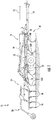
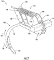
- FIG. 2 a perspective view of one embodiment of a shank assembly 100 for use with an agricultural implement is illustrated in accordance with aspects of the present subject matter.
- the shank assembly 100 will be described herein with reference to the implement 10 described above with reference to FIG. 1 .
- the disclosed shank assembly 100 may generally be utilized with implements having any other suitable implement configuration.
- the shank assembly 100 may include a shank 102 configured to be pivotable relative to the frame 16.
- the shank 102 may pivot out of the way of rocks or other impediments in the soil to prevent damage to the shank 102 or other components of the shank assembly 100.
- the shank 102 may generally include a base portion 104 pivotably coupled to frame mounting plates 106, such as at a pivot point 108.
- the frame mounting plates 106 may, in turn, be configured to be coupled to one of the frame members 18 of the frame 16.
- FIG. 2 shows two frame mounting plates 106 spaced apart from each other, it should be appreciated that the shank assembly 100 may include any suitable number or arrangement of frame mounting plates 106.
- the shank 102 may be pivotably coupled directly to one of the frame members 18. Additionally, the shank 102 may include a ground-engaging portion 110 extending from the base portion 104 along a curved or arcuate profile. The ground-engaging portion 110 may, in turn, include a tip end 112 that is configured to penetrate into or otherwise engage the ground as the implement 10 is being pulled through a field. In one embodiment, the ground engaging portion 110 may be configured as or include a chisel. However, one of ordinary skill in the art would appreciate that the ground engaging portion 110 may be configured as or include a sweep, tine, or any other suitable ground engaging tool.
- the shank assembly 100 may also include a biasing element 114, such as one or more springs, compressed between a first mounting location 116 and a second mounting location 118.
- the biasing element 114 is configured to exert a biasing force on the shank 102.
- the first mounting location 116 for the biasing element 114 may be defined by a portion of the frame mounting plates 106, such as via aligned apertures configured to receive a mounting pin or other suitable component provided in operative association with the adjacent end of the biasing element 114.
- the first mounting location 116 for the biasing element 114 may be defined by one of the frame members 18 or another component of the frame 16.
- the second mounting location 118 for the biasing element 114 may be defined by one or more reversible mounting plates 120 of the disclosed shank assembly 100.
- the biasing element 114 may be configured as one or more springs.
- the biasing element 114 may be configured as any other suitable biasing element.
- the biasing element 114 may be configured to exert a biasing force on the shank 102 to bias the shank 102 to a predetermined shank position (e.g., a home or base position) relative to the frame 16.
- the predetermined shank position may correspond to a shank position in which the shank 102 penetrates the soil to a desired depth.
- the biasing element 114 may permit relative movement between the shank 102 and the frame 16.
- the biasing element 114 may be configured to bias the shank 102 to pivot relative to the frame 16 in a first pivot direction (e.g., as indicated by arrow 124 in FIG. 2 ) until the shank 102 reaches the predetermined shank position.
- the biasing element 114 may also allow the shank 102 to pivot away from the predetermined shank position (e.g., to a shallower depth of penetration), such as in a second pivot direction (e.g., as indicated by arrow 122 in FIG. 2 ) opposite the first pivot direction 124, when encountering rocks or other impediments in the field.
- a second pivot direction e.g., as indicated by arrow 122 in FIG. 2
- the shank assembly 100 may include one or more reversible mounting plates 120 configured to define the second mounting location 118 for the biasing element 114 such that the biasing element 114 is supported or compressed between the first and second mounting locations 116, 118 (e.g., between the frame mounting plates 106 and the reversible mounting plates 120).
- the reversible mounting plates 120 may be configured to be installed or positioned relative to the biasing element 114 in one of a first orientation or a second orientation. As will be discussed, reversing the orientation of the reversible mounting plates 120 from the first orientation to the second orientation may change the biasing force that the biasing element 114 exerts on the shank 102. As shown in FIG.
- the reversible mounting plates 120 may be coupled to a portion of the shank 102, such as the base portion 104, and extend upwardly therefrom towards the second mounting location 118 for the biasing element 118.
- FIG. 2 illustrates two reversible mounting plates 120 spaced apart from each other, a person of ordinary skill in the art would appreciate that the shank assembly 100 may include any suitable number of reversible mounting plates 120.
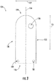
- the reversible mounting plate 120 may extend in a lengthwise direction (e.g., as indicated by arrow 125 in FIG. 3 ) between a forward or first end 126 and an aft or second end 128.
- the reversible mounting plate may also extend in a lateral direction (e.g., as indicated by arrow 127 in FIG. 3 ) between a first side 130 and a second side 132.
- the reversible mounting plate 120 may define a centerline 134 extending in the lengthwise direction 125 between the first and second ends 126, 128 of the plate 120 and positioned laterally between and equidistant from the first and second sides 130, 132. Additionally, in several embodiments, the reversible mounting plate 120 may also define a mounting aperture 136 positioned proximate to the second end 128 and offset or otherwise spaced apart from the centerline 134. As will be discussed, the mounting aperture 136 may define the second mounting location 118 for the biasing element 114. Additionally, in one embodiment, the reversible mounting plate 120 may define one or more apertures 138 positioned proximate to its first end 126 for use in coupling the reversible mounting plate 120 to the shank 102.
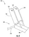
- FIG. 4 illustrates a partial perspective of the shank assembly 100 shown in FIG. 2 in accordance with aspects of the present subject matter.
- the shank assembly 100 may include two reversible mounting plates 120 spaced apart from each other.
- each reversible plate 120 may define an associated mounting plate aperture 136 that is offset from an associated centerline 134.
- the mounting plate apertures 136 defined by each plate 120 are aligned so as to be configured to receive a mounting pin or other suitable component provided in operative association with the adjacent end of the biasing element 114.
- FIGS. 5 and 6 respectively illustrate an embodiment of the disclosed shank assembly 100 when the reversible mounting plates 120 are installed relative to the biasing element 114 in the first and second orientations. More specifically, as indicated above, each reversible mounting plate 120 defines a mounting aperture 136 that is laterally offset from the centerline 134 of such plate 120. In this respect, the position of the second mounting location 118 (e.g., as defined at the aligned mounting apertures 136 of the mounting plates 120) relative to the first mounting location 116 may change when the orientation of the mounting plates 120 are reversed (e.g., rotated one hundred and eighty degrees about the centerline 134). As such, the distance between the first and second mounting locations 116, 118 may differ depending on whether the reversible mounting plate 120 are installed at the first orientation or the second orientation relative to the biasing element 114.
- a first distance (e.g., as indicated by arrow 140 in FIG. 5 ) may be defined between the first and second mounting locations 116, 118 when the reversible mounting plates 120 are installed relative to the biasing element 114 at in the first orientation.
- a second distance (e.g., as indicated by arrow 142 in FIG. 6 ) may be defined between the first and second mounting locations 116, 118 when the reversible mounting plates 120 are installed relative to the biasing element 114 at the second orientation.
- the first distance 140 is less than the second distance 142.
- the biasing element 114 exerts a first biasing force on the shank 102 when the reversible mounting plates 120 are installed at the first orientation (e.g., as shown in FIG. 5 ) and a second biasing force on the shank 102 when the reversible mounting plates 120 are installed at the second orientation (e.g., as shown in FIG. 6 ).
- first orientation e.g., as shown in FIG. 5
- second biasing force on the shank 102 e.g., as shown in FIG. 6
- the first biasing force is greater than the second biasing force.
- the mounting plates 120 may installed at the first orientation relative to the biasing element 114.
- the mounting plates may be installed at the second orientation relative to the biasing element 114.
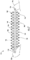
- FIG. 7 a cross-sectional, partial view of one embodiment of the disclosed shank assembly 100 is illustrated in accordance with aspects of the present subject matter, particularly illustrating the shank assembly 100 including a pair of concentric biasing elements 144, 146 compressed between the first and second mounting locations 116, 118 defined by the opposed mounting plates 106, 120.
- the shank assembly 100 include a first outer spring 144 and a second inner spring 146 positioned concentrically within the first spring 144.
- the first and second springs 144, 146 may have different spring constants.
- the first and second springs 114, 146 may provide additional adjustability of the biasing force exerted on the shank 102.
- such springs 144, 146 may be configured to be installed onto the shank assembly 100 individually or in combination to adjust the biasing force applied on the shank 102. For example, by only installing the first outer spring 144 between the first and second mounting locations 116, 118, a first biasing force may be exerted on the shank 102. Similarly, by only installing the second inner spring 146 between the first and second mounting locations 116, 118, a different, second biasing force may be exerted on the shank 102. Moreover, by installing both springs between the first and second mounting locations 116, 118 (e.g., as shown in FIG.
- a third biasing force may be exerted on the shank 102 that differs from both the first biasing force and the second biasing force.
- the shank assembly 100 is shown as only including two concentrically aligned springs 144, 146, a person of ordinary skill in the art would appreciate that the shank assembly 100 may include a greater number of concentrically aligned springs to provide even further flexibility for adjusting the biasing force applied on the shank 102.
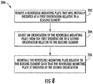
- FIG. 8 a flow diagram of one embodiment of a method 200 for adjusting a biasing force exerted on a shank of an agricultural implement is illustrated in accordance with aspects of the present subject matter.
- the method 200 will be described herein with reference to the implement 10 and the shank assemblies 100 described above with reference to FIGS. 1-7 .
- the disclosed method 200 may generally be utilized to adjust a biasing force on a shank for any agricultural implement having any suitable implement configuration and/or of any shank assembly having any suitable shank assembly configuration.
- FIG. 8 depicts steps performed in a particular order for purposes of illustration and discussion, the methods discussed herein are not limited to any particular order or arrangement.
- steps of the methods disclosed herein can be omitted, rearranged, combined, and/or adapted in various ways without deviating from the scope of the present disclosure.
- the method 200 may include removing a reversible mounting plate from an associated shank assembly that is initially oriented at a first orientation relative to a biasing element of a shank assembly.
- the reversible mounting plate 120 may be positioned relative to the biasing element 114 at the first orientation described above with reference to FIG. 5 .
- the biasing element 114 may have been configured to exert a first biasing force on the shank 102. It should be appreciated that, in embodiments where the shank assembly 100 includes two reversible mounting plates 120, the method 200, at (202), may include removing both of the reversible mounting plates 120.
- the method 200 may include reversing an orientation of the reversible mounting plate from the first orientation to a second orientation. As described above, reversing the orientation of the reversible mounting plate 120 changes the distance between the first and second mounting locations 116, 118 for the biasing element 114, thereby changing the biasing force that the biasing element 114 exerts on the shank 102. It should be appreciated that, in embodiments where the shank assembly 100 includes two reversible mounting plates 120, the method 200, at (204), may include reversing the orientations of both of the reversible mounting plates 120.
- the method 200 may include reinstalling the reversible mounting plate relative to the biasing element such that the reversible mounting plate is oriented at the second orientation and the biasing element exerts a second biasing force on the shank.
- the reversible mounting plate 120 may be positioned relative to the biasing element 114 at the second orientation described above with reference to FIG. 6 .
- the biasing element 114 may exert a second biasing force on the shank 102 that differs from the original first biasing force.
- the method 200, at (206) may include reinstalling both of the reversible mounting plates 120 relative to the biasing element 114.
- the method 200 may also include compressing or installing one or more biasing elements (e.g., springs) between the first and second mounting locations.
- a first spring 144 and/or a second spring 146 may be compressed or installed between the first and second mounting locations 116, 118 of the biasing element 114.
- the second spring 146 may be positioned concentrically within the first spring 144.
Abstract
Description
- The present disclosure generally relates to agricultural implements and, more particularly, to shank assemblies with adjustable or selectable biasing forces for use with agricultural implements and related methods.
- It is well known that, to attain the best agricultural performance from a field, a farmer must cultivate the soil, typically through a tillage operation. Modern farmers perform tillage operations by pulling a tillage implement behind an agricultural work vehicle, such as a tractor. Tillage implements typically include a plurality of shank assemblies. Each shank assembly may include a shank pivotably coupled to a frame of the tillage implement and configured to penetrate the soil to a particular depth. Tillage implements may also include biasing elements, such as springs, configured to exert biasing forces on the shanks. This configuration may allow the shanks to maintain the particular depth of soil penetration as the agricultural work vehicle pulls the tillage implement through the field. Additionally, this configuration may also permit the shanks to pivot out of the way of rocks or other impediments in the soil, thereby preventing damage to the shank assemblies or other components on the implement.
- Each biasing element generally exerts a specific predetermined biasing force on the shank of the corresponding shank assembly. In this respect, the shank may pivot relative to the frame when the soil or impediments therein exert forces on the shank that exceed the biasing force provided by the biasing element. However, since the biasing force provided by conventional biasing elements is not adjustable, the shank assembly is not able to accommodate changes in soil conditions, such as a change in soil type. Such changes may result in excessive pivoting or tripping of the shank or undesirable levels of penetration depth of the shank.
- Accordingly, an improved shank assembly with adjustable or selectable biasing forces for use with an agricultural implement and related methods would be welcomed in the technology.
- Aspects and advantages of the technology will be set forth in part in the following description, or may be obvious from the description, or may be learned through practice of the technology.
- In one aspect, the present subject matter is directed to a shank assembly for an agricultural implement. The shank assembly may include a shank and a biasing element configured to exert a biasing force on the shank. The biasing element may be compressed between a first mounting location for the biasing element and a second mounting location for the biasing element. The shank assembly may also include a reversible mounting plate configured to be positioned relative to the biasing element in one of a first orientation or a second orientation. The reversible mounting plate may define a mounting aperture positioned at the second mounting location for the biasing element. The mounting aperture may be offset from a centerline of the reversible mounting plate such that a position of the second mounting location relative to the first mounting location differs depending on whether the reversible mounting plate is provided in the first orientation or the second orientation relative to the biasing element. The biasing element may exert a first biasing force on the shank when the reversible member is oriented in the first orientation and a second biasing force on the shank when the reversible member is oriented in the second orientation. The first biasing force may be different than the second biasing force.
- In another aspect, the present subject matter is directed to an agricultural implement. The agricultural implement may include a frame and a shank configured to be pivotable relative to the frame. The agricultural element may also include a biasing element configured to exert a biasing force on the shank. The biasing element may be compressed between a first mounting location for the biasing element and a second mounting location for the biasing element. The agricultural implement may further include a reversible mounting plate configured to be positioned relative to the biasing element in one of a first orientation or a second orientation. The reversible mounting plate may define a mounting aperture positioned at the second mounting location for the biasing element. The mounting aperture may be offset from a centerline of the reversible mounting plate such that a position of the second mounting location relative to the first mounting location differs depending on whether the reversible mounting plate is provided in the first orientation or the second orientation relative to the biasing element. The biasing element may exert a first biasing force on the shank when the reversible member is oriented in the first orientation and a second biasing force on the shank when the reversible member is oriented in the second orientation. The first biasing force may be different than the second biasing force.
- In a further aspect, the present subject matter is directed to a method for adjusting a biasing force on a shank of a shank assembly configured to be provided in operative association with an agricultural implement. The shank may be pivotably coupled to a frame of the implement. The shank assembly may further include a biasing element configured to exert a biasing force on the shank. The biasing element may be compressed between a first mounting location for the biasing element and a second mounting location for the biasing element. The method may include removing a reversible mounting plate of the shank assembly that was initially oriented at a first orientation relative to the biasing element. The reversible mounting plate may define a mounting aperture positioned at the second mounting location for the biasing element. The mounting aperture may be offset from a centerline of the reversible mounting plate such that a position of the second mounting location relative to the first mounting location differs depending on whether the reversible mounting plate is provided in the first orientation or a second orientation relative to the biasing element. The biasing element may be configured to exert a first biasing force on the shank when the reversible member is oriented in the first orientation. The method may further include adjusting the orientation of the reversible mounting plate from the first orientation to the second orientation. Additionally, the method may include installing the reversible mounting plate relative to the biasing element such that the reversible mounting plate is oriented at the second orientation and the biasing element exerts a second biasing force on the shank. The second biasing force may be different than the first biasing force.
- These and other features, aspects and advantages of the present technology will become better understood with reference to the following description and appended claims. The accompanying drawings, which are incorporated in and constitute a part of this specification, illustrate embodiments of the technology and, together with the description, serve to explain the principles of the technology.
- A full and enabling disclosure of the present technology, including the best mode thereof, directed to one of ordinary skill in the art, is set forth in the specification, which makes reference to the appended figures, in which:
-
FIG. 1 illustrates a side view of one embodiment of an agricultural implement in accordance with aspects of the present subject matter; -
FIG. 2 illustrates a perspective view of one embodiment of a shank assembly in accordance with aspects of the present subject matter, particularly illustrating the shank assembly including a reversible mounting plate for adjusting a biasing force on a shank; -
FIG. 3 illustrates a side view of one embodiment of a reversible mounting plate in accordance with aspects of the present subject matter, particularly illustrating the reversible mounting plate defining a mounting aperture offset from a centerline of the reversible mounting plate; -
FIG. 4 illustrates a partial perspective view the shank assembly shown inFIG. 2 in accordance with aspects of the present subject matter, particularly illustrating a pair of reversible mounting plates defining a pair mounting apertures that are aligned with each other; -
FIG. 5 illustrates a side view of one embodiment of a shank assembly in accordance with aspects of the present subject matter, particularly illustrating a biasing element defining a first compressed length when the associated reversible mounting plate is oriented at a first orientation relative to the biasing element; -
FIG. 6 illustrates another side view of the shank assembly shown inFIG. 5 , particularly illustrating the biasing element defining a second compressed length after the reversible mounting plate has been installed relative to the biasing element at a second orientation that differs from the first orientation; -
FIG. 7 illustrates a cross-sectional view of one embodiment of biasing elements suitable for use with the disclosed shank assembly in accordance with aspects of the present subject matter, particularly illustrating a first spring and a second spring positioned concentrically within the first spring; and -
FIG. 8 illustrates a flow diagram of one embodiment of a method for adjusting a biasing force applied on a shank of an agricultural implement in accordance with aspects of the present subject matter. - Repeat use of reference characters in the present specification and drawings is intended to represent the same or analogous features or elements of the present technology.
- Reference now will be made in detail to embodiments of the invention, one or more examples of which are illustrated in the drawings. Each example is provided by way of explanation of the invention, not limitation of the invention. In fact, it will be apparent to those skilled in the art that various modifications and variations can be made in the present invention without departing from the scope or spirit of the invention. For instance, features illustrated or described as part of one embodiment can be used with another embodiment to yield a still further embodiment. Thus, it is intended that the present invention covers such modifications and variations as come within the scope of the appended claims and their equivalents.
- In general, the present subject matter is directed to a shank assembly for use with an agricultural implement and related adjustment methods. Specifically, the disclosed shank assembly may include one or more components that allow for the biasing force applied on the associated shank to be adjusted, as desired, to accommodate differing soil conditions. For example, in several embodiments, the shank assembly may include a shank and a biasing element (e.g., a spring) configured to exert a biasing force on the shank. The biasing element may be compressed between first and second mounting locations. Additionally, the shank assembly may include a reversible mounting plate positioned at one of the mounting locations for the biasing element, with the mounting plate being reversible so as to be positioned in either a first orientation or a second orientation relative to the biasing element. As will be described below, a mounting aperture of the reversible mounting plate may be offset from an associated centerline of the plate. In this respect, the relative position of the mounting locations for the biasing element may differ depending on whether the reversible mounting plate is installed at the first orientation or the second orientation relative to the biasing element. That is, the mounting locations may be spaced apart from one another by a first distance when the reversible mounting plate is installed at the first orientation; whereas, the mounting locations may be spaced apart from one another by a different, second distance when the reversible mounting plate is installed at the second orientation. As a result, by adjusting the orientation of the mounting plate relative to the biasing element between the first and second orientations, the active length of the biasing element (e.g., the compressed length of the spring) may be varied. As such, the biasing element may be configured to may exert one biasing force on the shank when the reversible member is oriented in the first orientation and a different biasing force on the shank when the reversible member is oriented in the second orientation.
- Referring now to
FIG. 1 , a side view of one embodiment of an agricultural implement 10 is illustrated in accordance with aspects of the present subject matter. As shown, the implement 10 may be configured to be towed along a direction oftravel 12 by a work vehicle (not shown), such as a tractor or other agricultural work vehicle. For example, the work vehicle may be coupled to the implement 10 via ahitch assembly 14 or using any other suitable attachments means. As shown, thehitch assembly 14 may be coupled to aframe 16 of the implement 10 to facilitate towing the implement 10 in the direction oftravel 12. - The implement 10 may include the implement
frame 16. As shown, theframe 16 generally includes a plurality ofstructural frame members 18, such as beams, bars, and/or the like, configured to support or couple to a plurality of components. For example, in one embodiment, theframe 16 may be configured to support acultivator 20, which may be configured to till or otherwise break the soil over which the implement 10 travels to create a seedbed. In this respect, thecultivator 20 may include a plurality ofshank assemblies 100, which are pulled through the soil as the implement 10 moves across the field in the direction oftravel 14. Additionally, a pair ofwheels 22 may be coupled to the implementframe 16 that support the weight of theframe 16 and thecultivator 20, thereby enabling the implement 10 to be towed across the field. - Additionally, as shown in
FIG. 1 , the implement 10 may also include aharrow 24. As is generally understood, theharrow 24 may be configured to be pivotally coupled to theframe 16. Theharrow 24 may include a plurality ofground engaging elements 26, such as tines or spikes, which are configured to level or otherwise flatten any windrows or ridges in the soil created by thecultivator 20. Specifically, theground engaging elements 26 may be configured to be pulled through the soil as the implement 10 moves across the field in the direction oftravel 12. It should be appreciated that the implement 10 may include any suitable number ofharrows 24. In fact, some embodiments of the implement 10 may not include anyharrows 24. - Moreover, in one embodiment, the implement 10 may optionally include a basket or
rotary firming wheel 28. As is generally understood, thebasket 28 may be configured to reduce the number of clods in the soil and/or firm the soil over which the implement 10 travels. As shown, thebasket 28 may be configured to be pivotally coupled to theharrows 24. Alternately, thebasket 28 may be configured to be pivotably coupled to theframe 16 or any other suitable location of the implement 10. It should be appreciated that the implement 10 may include any suitable number ofbaskets 28. In fact, some embodiments of the implement 10 may not include anybaskets 28. - It should be appreciated that the configuration of the implement 10 described above and shown in
FIG. 1 is provided only to place the present subject matter in an exemplary field of use. Thus, it should be appreciated that the present subject matter may be readily adaptable to any manner of implement configuration. - Referring now to
FIG. 2 , a perspective view of one embodiment of ashank assembly 100 for use with an agricultural implement is illustrated in accordance with aspects of the present subject matter. In general, theshank assembly 100 will be described herein with reference to the implement 10 described above with reference toFIG. 1 . However, it should be appreciated by those of ordinary skill in the art that the disclosedshank assembly 100 may generally be utilized with implements having any other suitable implement configuration. - As shown in
FIG. 2 , theshank assembly 100 may include ashank 102 configured to be pivotable relative to theframe 16. In general, theshank 102 may pivot out of the way of rocks or other impediments in the soil to prevent damage to theshank 102 or other components of theshank assembly 100. As shown, in one embodiment, theshank 102 may generally include abase portion 104 pivotably coupled to frame mountingplates 106, such as at apivot point 108. Theframe mounting plates 106 may, in turn, be configured to be coupled to one of theframe members 18 of theframe 16. AlthoughFIG. 2 shows twoframe mounting plates 106 spaced apart from each other, it should be appreciated that theshank assembly 100 may include any suitable number or arrangement offrame mounting plates 106. Alternatively, theshank 102 may be pivotably coupled directly to one of theframe members 18. Additionally, theshank 102 may include a ground-engagingportion 110 extending from thebase portion 104 along a curved or arcuate profile. The ground-engagingportion 110 may, in turn, include atip end 112 that is configured to penetrate into or otherwise engage the ground as the implement 10 is being pulled through a field. In one embodiment, theground engaging portion 110 may be configured as or include a chisel. However, one of ordinary skill in the art would appreciate that theground engaging portion 110 may be configured as or include a sweep, tine, or any other suitable ground engaging tool. - The
shank assembly 100 may also include abiasing element 114, such as one or more springs, compressed between a first mountinglocation 116 and a second mountinglocation 118. In general, the biasingelement 114 is configured to exert a biasing force on theshank 102. As illustrated inFIG. 2 , in one embodiment, the first mountinglocation 116 for the biasingelement 114 may be defined by a portion of theframe mounting plates 106, such as via aligned apertures configured to receive a mounting pin or other suitable component provided in operative association with the adjacent end of the biasingelement 114. Alternatively, the first mountinglocation 116 for the biasingelement 114 may be defined by one of theframe members 18 or another component of theframe 16. Moreover, as will be discussed, the second mountinglocation 118 for the biasingelement 114 may be defined by one or more reversible mountingplates 120 of the disclosedshank assembly 100. As shown inFIG. 2 , the biasingelement 114 may be configured as one or more springs. However, it should be appreciated that the biasingelement 114 may be configured as any other suitable biasing element. - In several embodiments, the biasing
element 114 may be configured to exert a biasing force on theshank 102 to bias theshank 102 to a predetermined shank position (e.g., a home or base position) relative to theframe 16. In general, the predetermined shank position may correspond to a shank position in which theshank 102 penetrates the soil to a desired depth. In operation, the biasingelement 114 may permit relative movement between theshank 102 and theframe 16. For example, the biasingelement 114 may be configured to bias theshank 102 to pivot relative to theframe 16 in a first pivot direction (e.g., as indicated byarrow 124 inFIG. 2 ) until theshank 102 reaches the predetermined shank position. The biasingelement 114 may also allow theshank 102 to pivot away from the predetermined shank position (e.g., to a shallower depth of penetration), such as in a second pivot direction (e.g., as indicated byarrow 122 inFIG. 2 ) opposite thefirst pivot direction 124, when encountering rocks or other impediments in the field. - Additionally, as indicated above, the
shank assembly 100 may include one or more reversible mountingplates 120 configured to define the second mountinglocation 118 for the biasingelement 114 such that the biasingelement 114 is supported or compressed between the first and second mountinglocations 116, 118 (e.g., between theframe mounting plates 106 and the reversible mounting plates 120). In general, the reversible mountingplates 120 may be configured to be installed or positioned relative to the biasingelement 114 in one of a first orientation or a second orientation. As will be discussed, reversing the orientation of the reversible mountingplates 120 from the first orientation to the second orientation may change the biasing force that the biasingelement 114 exerts on theshank 102. As shown inFIG. 2 , in one embodiment, the reversible mountingplates 120 may be coupled to a portion of theshank 102, such as thebase portion 104, and extend upwardly therefrom towards the second mountinglocation 118 for the biasingelement 118. AlthoughFIG. 2 illustrates two reversible mountingplates 120 spaced apart from each other, a person of ordinary skill in the art would appreciate that theshank assembly 100 may include any suitable number of reversible mountingplates 120. - Referring now to
FIG. 3 , a side view of one of the reversible mountingplates 120 shown inFIG. 2 is illustrated in accordance with aspects of the present subject matter. As shown, the reversible mountingplate 120 may extend in a lengthwise direction (e.g., as indicated byarrow 125 inFIG. 3 ) between a forward orfirst end 126 and an aft orsecond end 128. The reversible mounting plate may also extend in a lateral direction (e.g., as indicated byarrow 127 inFIG. 3 ) between afirst side 130 and asecond side 132. In this respect, the reversible mountingplate 120 may define acenterline 134 extending in thelengthwise direction 125 between the first and second ends 126, 128 of theplate 120 and positioned laterally between and equidistant from the first andsecond sides plate 120 may also define a mountingaperture 136 positioned proximate to thesecond end 128 and offset or otherwise spaced apart from thecenterline 134. As will be discussed, the mountingaperture 136 may define the second mountinglocation 118 for the biasingelement 114. Additionally, in one embodiment, the reversible mountingplate 120 may define one ormore apertures 138 positioned proximate to itsfirst end 126 for use in coupling the reversible mountingplate 120 to theshank 102. -
FIG. 4 illustrates a partial perspective of theshank assembly 100 shown inFIG. 2 in accordance with aspects of the present subject matter. Specifically, as indicated above, theshank assembly 100 may include two reversible mountingplates 120 spaced apart from each other. In one embodiment, eachreversible plate 120 may define an associated mountingplate aperture 136 that is offset from an associatedcenterline 134. As shown, the mountingplate apertures 136 defined by eachplate 120 are aligned so as to be configured to receive a mounting pin or other suitable component provided in operative association with the adjacent end of the biasingelement 114. -
FIGS. 5 and6 respectively illustrate an embodiment of the disclosedshank assembly 100 when the reversible mountingplates 120 are installed relative to the biasingelement 114 in the first and second orientations. More specifically, as indicated above, each reversible mountingplate 120 defines a mountingaperture 136 that is laterally offset from thecenterline 134 ofsuch plate 120. In this respect, the position of the second mounting location 118 (e.g., as defined at the aligned mountingapertures 136 of the mounting plates 120) relative to the first mountinglocation 116 may change when the orientation of the mountingplates 120 are reversed (e.g., rotated one hundred and eighty degrees about the centerline 134). As such, the distance between the first and second mountinglocations plate 120 are installed at the first orientation or the second orientation relative to the biasingelement 114. - For example, a first distance (e.g., as indicated by
arrow 140 inFIG. 5 ) may be defined between the first and second mountinglocations plates 120 are installed relative to the biasingelement 114 at in the first orientation. Conversely, a second distance (e.g., as indicated byarrow 142 inFIG. 6 ) may be defined between the first and second mountinglocations plates 120 are installed relative to the biasingelement 114 at the second orientation. As shown inFIGS. 5 and6 , given the configuration of the mountingplates 120, thefirst distance 140 is less than thesecond distance 142. As should be appreciated, changing the distance between the first and second mountinglocations element 114, which, in turn, may adjusts the biasing force that the biasingelement 114 exerts on theshank 102. For example, in one embodiment, the biasingelement 114 exerts a first biasing force on theshank 102 when the reversible mountingplates 120 are installed at the first orientation (e.g., as shown inFIG. 5 ) and a second biasing force on theshank 102 when the reversible mountingplates 120 are installed at the second orientation (e.g., as shown inFIG. 6 ). For example, given the configuration of the mountingplates 120 shown inFIGS. 5 and6 , the first biasing force is greater than the second biasing force. Thus, if a greater down force is desired on theshank 102, the mountingplates 120 may installed at the first orientation relative to the biasingelement 114. In contrast, if a reduced down force is desired, the mounting plates may be installed at the second orientation relative to the biasingelement 114. - Referring now to
FIG. 7 , a cross-sectional, partial view of one embodiment of the disclosedshank assembly 100 is illustrated in accordance with aspects of the present subject matter, particularly illustrating theshank assembly 100 including a pair ofconcentric biasing elements locations plates shank assembly 100 include a firstouter spring 144 and a secondinner spring 146 positioned concentrically within thefirst spring 144. In several embodiments, the first andsecond springs second springs shank 102. More specifically,such springs shank assembly 100 individually or in combination to adjust the biasing force applied on theshank 102. For example, by only installing the firstouter spring 144 between the first and second mountinglocations shank 102. Similarly, by only installing the secondinner spring 146 between the first and second mountinglocations shank 102. Moreover, by installing both springs between the first and second mountinglocations 116, 118 (e.g., as shown inFIG. 7 ), a third biasing force may be exerted on theshank 102 that differs from both the first biasing force and the second biasing force. Although theshank assembly 100 is shown as only including two concentrically alignedsprings shank assembly 100 may include a greater number of concentrically aligned springs to provide even further flexibility for adjusting the biasing force applied on theshank 102. - Referring now to
FIG. 8 , a flow diagram of one embodiment of amethod 200 for adjusting a biasing force exerted on a shank of an agricultural implement is illustrated in accordance with aspects of the present subject matter. In general, themethod 200 will be described herein with reference to the implement 10 and theshank assemblies 100 described above with reference toFIGS. 1-7 . However, it should be appreciated by those of ordinary skill in the art that the disclosedmethod 200 may generally be utilized to adjust a biasing force on a shank for any agricultural implement having any suitable implement configuration and/or of any shank assembly having any suitable shank assembly configuration. In addition, althoughFIG. 8 depicts steps performed in a particular order for purposes of illustration and discussion, the methods discussed herein are not limited to any particular order or arrangement. One skilled in the art, using the disclosures provided herein, will appreciate that various steps of the methods disclosed herein can be omitted, rearranged, combined, and/or adapted in various ways without deviating from the scope of the present disclosure. - As shown in
FIG. 8 , at (202), themethod 200 may include removing a reversible mounting plate from an associated shank assembly that is initially oriented at a first orientation relative to a biasing element of a shank assembly. For instance, prior to removal, the reversible mountingplate 120 may be positioned relative to the biasingelement 114 at the first orientation described above with reference toFIG. 5 . In such an embodiment, given thedistance 140 defined between the first and second mountinglocations element 114, the biasingelement 114 may have been configured to exert a first biasing force on theshank 102. It should be appreciated that, in embodiments where theshank assembly 100 includes two reversible mountingplates 120, themethod 200, at (202), may include removing both of the reversible mountingplates 120. - Additionally, at (204), the
method 200 may include reversing an orientation of the reversible mounting plate from the first orientation to a second orientation. As described above, reversing the orientation of the reversible mountingplate 120 changes the distance between the first and second mountinglocations element 114, thereby changing the biasing force that the biasingelement 114 exerts on theshank 102. It should be appreciated that, in embodiments where theshank assembly 100 includes two reversible mountingplates 120, themethod 200, at (204), may include reversing the orientations of both of the reversible mountingplates 120. - Moreover, as shown in
FIG. 8 , at (206), themethod 200 may include reinstalling the reversible mounting plate relative to the biasing element such that the reversible mounting plate is oriented at the second orientation and the biasing element exerts a second biasing force on the shank. For instance, after reinstallation, the reversible mountingplate 120 may be positioned relative to the biasingelement 114 at the second orientation described above with reference toFIG. 6 . In such an embodiment, given thedistance 142 defined between the first and second mountinglocations element 114, the biasingelement 114 may exert a second biasing force on theshank 102 that differs from the original first biasing force. It should be appreciated that, in embodiments where theshank assembly 100 includes two reversible mountingplates 120, themethod 200, at (206), may include reinstalling both of the reversible mountingplates 120 relative to the biasingelement 114. - Furthermore, in several embodiments, the
method 200 may also include compressing or installing one or more biasing elements (e.g., springs) between the first and second mounting locations. For instance, as described above with reference toFIG. 7 , afirst spring 144 and/or asecond spring 146 may be compressed or installed between the first and second mountinglocations element 114. As described above, when installing bothsprings locations second spring 146 may be positioned concentrically within thefirst spring 144. - This written description uses examples to disclose the technology, including the best mode, and also to enable any person skilled in the art to practice the technology, including making and using any devices or systems and performing any incorporated methods. The patentable scope of the technology is defined by the claims, and may include other examples that occur to those skilled in the art. Such other examples are intended to be within the scope of the claims if they include structural elements that do not differ from the literal language of the claims, or if they include equivalent structural elements with insubstantial differences from the literal language of the claims.
Claims (15)
- A shank assembly (100) for an agricultural implement (10), the shank assembly (100) comprising a shank (102), a biasing element (114) configured to exert a biasing force on the shank (102), the biasing element (114) being compressed between a first mounting location (116) for the biasing element (114) and a second mounting location (118) for the biasing element (114), the shank assembly (100) further comprising a reversible mounting plate (120) configured to be positioned relative to the biasing element (114) in one of a first orientation or a second orientation, the reversible mounting plate (120) defining a mounting aperture (136) positioned at the second mounting location (118) for the biasing element (114), the reversible mounting plate (120) being characterized by:the mounting aperture (136) being offset from a centerline (134) of the reversible mounting plate (120) such that a position of the second mounting location (118) relative to the first mounting location (116) differs depending on whether the reversible mounting plate (120) is provided in the first orientation or the second orientation relative to the biasing element (114);wherein the biasing element (114) exerts a first biasing force on the shank (102) when the reversible mounting plate (120) is oriented in the first orientation and a second biasing force on the shank (102) when the reversible mounting plate (120) is oriented in the second orientation, the first biasing force being different than the second biasing force.
- The shank assembly (100) as in claim 1, wherein the biasing element (114) defines a first compressed length between the first (116) and second mounting locations (118) when the reversible mounting plate (120) is oriented in the first orientation and a second compressed length between the first (116) and second mounting locations (118) when the reversible mounting plate (120) is oriented in the second orientation, the first compressed length being different than the second compressed length.
- The shank assembly (100) as in any preceding claim, wherein the biasing element (114) comprises a first spring (144).
- The shank assembly (100) as in any preceding claim, wherein the biasing element (114) comprises a second spring (146) positioned concentrically within the first spring (144).
- The shank assembly (100) as in any preceding claim, wherein the first spring (144) has a spring constant that differs from a spring constant of the second spring (146).
- The shank assembly (100) as in any preceding claim, wherein the reversible mounting plate (120) corresponds to a first reversible mounting plate (120) and the mounting aperture (136) corresponds to a first mounting aperture (136), the reversible mounting plate (120) further comprising a second reversible mounting plate (120) spaced apart from the first reversible plate (120), the second reversible mounting plate (120) defining a second mounting aperture (136) configured to be aligned with the first mounting aperture (136) at the second mounting location (118).
- The shank assembly (100) as in any preceding claim, wherein the reversible mounting plate (120) is coupled to a portion of the shank (102).
- The shank assembly (100) as in any preceding claim, wherein the first mounting location (116) is defined by at least one mounting plate (120) configured to be coupled to a frame (16) of the agricultural implement (10).
- The shank assembly (100) as in any preceding claim, wherein the shank (102) is pivotably coupled to the at least one mounting plate (120).
- A method (200) for adjusting a biasing force on a shank (102) of a shank assembly (100) configured to be provided in operative association with an agricultural implement (10), the shank (102) being pivotably coupled to a frame (16) of the implement (10), the shank assembly (100) further including a biasing element (114) configured to exert a biasing force on the shank (102), the biasing element (114) being compressed between a first mounting location (116) for the biasing element (114) and a second mounting location (118) for the biasing element (114), the method (200) comprising removing a reversible mounting plate (120) of the shank assembly (100) that was initially oriented at a first orientation relative to the biasing element (114), the reversible mounting plate (120) defining a mounting aperture (136) positioned at the second mounting location (118) for the biasing element (114), the method (200) being characterized by:
the mounting aperture (136) being offset from a centerline (134) of the reversible mounting plate (120) such that a position of the second mounting location (118) relative to the first mounting location (116) differs depending on whether the reversible mounting plate (120) is provided in the first orientation or a second orientation relative to the biasing element (114), the biasing element (114) configured to exert a first biasing force on the shank (102) when the reversible mounting plate (120) is oriented in the first orientation, the method (200) further comprising:adjusting the orientation of the reversible mounting plate (120) from the first orientation to the second orientation; andreinstalling the reversible mounting plate (120) relative to the biasing element (114) such that the reversible mounting plate (120) is oriented at the second orientation and the biasing element (114) exerts a second biasing force on the shank (102), the second biasing force being different than the first biasing force. - The method (200) as in claim 10, wherein the biasing element (114) defines a first compressed length between the first (116) and second mounting locations (118) when the reversible mounting plate (120) is oriented in the first orientation and a second compressed length between the first (116) and second mounting locations (118) when the reversible mounting plate (120) is oriented in the second orientation, the first compressed length being different than the second compressed length.
- The method (200) as in any of claims 10 or 11, wherein the biasing element (114) comprises a first spring (144).
- The method (200) as in any of claims 10 through 12, wherein the biasing element (114) comprises a second spring (146) positioned concentrically within the first spring (144).
- The method (200) as in any of claims 10 through 13, wherein the first spring (144) has a spring constant that differs from a spring constant of the second spring (146).
- The method (200) as in any of claims 10 through 14, wherein the reversible mounting plate (120) corresponds to a first reversible mounting plate (120) and the mounting aperture (136) corresponds to a first mounting aperture (136), the reversible mounting plate (120) further comprising a second reversible mounting plate (120) spaced apart from the first reversible plate (120), the second reversible mounting plate (120) defining a second mounting aperture (136) configured to be aligned with the first mounting aperture (136) at the second mounting location (118).
Applications Claiming Priority (1)
| Application Number | Priority Date | Filing Date | Title |
|---|---|---|---|
| US15/586,372 US10412875B2 (en) | 2017-05-04 | 2017-05-04 | Shank assembly for an agricultural implement with adjustable biasing forces and related methods |
Publications (1)
| Publication Number | Publication Date |
|---|---|
| EP3398416A1 true EP3398416A1 (en) | 2018-11-07 |
Family
ID=62110925
Family Applications (1)
| Application Number | Title | Priority Date | Filing Date |
|---|---|---|---|
| EP18170453.7A Withdrawn EP3398416A1 (en) | 2017-05-04 | 2018-05-02 | Shank assembly for an agricultural implement with adjustable biasing forces and related methods |
Country Status (2)
| Country | Link |
|---|---|
| US (1) | US10412875B2 (en) |
| EP (1) | EP3398416A1 (en) |
Families Citing this family (8)
| Publication number | Priority date | Publication date | Assignee | Title |
|---|---|---|---|---|
| DE102016112522A1 (en) * | 2016-07-07 | 2018-01-11 | Lemken Gmbh & Co. Kg | Soil cultivation device with overload protection |
| PL3554209T3 (en) * | 2016-12-16 | 2022-06-20 | Agco Corporation | Implement contouring toolbar |
| USD927560S1 (en) * | 2017-09-21 | 2021-08-10 | Kverneland Group Les Landes Génusson S.A.S. | C-tine |
| US11470755B2 (en) * | 2018-11-12 | 2022-10-18 | Deere & Company | Adjustable rolling basket assembly |
| USD940208S1 (en) * | 2019-05-15 | 2022-01-04 | Ausplow Pty. Ltd. | Plow digging blade |
| USD946058S1 (en) * | 2019-08-23 | 2022-03-15 | Milson Foundry Nz Limited | Twisted shovel |
| USD946057S1 (en) * | 2019-08-23 | 2022-03-15 | Milson Foundry Nz Limited | Twisted shovel |
| US11828031B2 (en) * | 2019-11-26 | 2023-11-28 | Ricky A. Weihl | Plow assembly linkage |
Citations (6)
| Publication number | Priority date | Publication date | Assignee | Title |
|---|---|---|---|---|
| US3258076A (en) * | 1964-10-07 | 1966-06-28 | Portable Elevator Mfg Company | Adjustable spring clamp shank assembly |
| US3700038A (en) * | 1971-03-03 | 1972-10-24 | Deere & Co | Adjustable spring trip shank assembly |
| US4700785A (en) * | 1986-03-24 | 1987-10-20 | Deere & Company | Furrow opener assembly with integral down-pressure adjustment |
| US5461995A (en) * | 1994-02-25 | 1995-10-31 | Dean A. Winterton | Rotary row cleaner with reversible spring |
| AU676503B2 (en) * | 1992-11-26 | 1997-03-13 | Lemming Investments Pty Ltd | Cultivator tyne assembly |
| EP2656708A1 (en) * | 2012-04-28 | 2013-10-30 | Paul Treffler | Harrow |
Family Cites Families (40)
| Publication number | Priority date | Publication date | Assignee | Title |
|---|---|---|---|---|
| US631232A (en) | 1899-02-17 | 1899-08-15 | J I Case Plow Works | Automatic spring-trip for cultivator-shovels. |
| US1004224A (en) | 1911-07-28 | 1911-09-26 | Bateman Mfg Company | Spring attachment for teeth of agricultural implements. |
| US2935148A (en) * | 1956-03-26 | 1960-05-03 | William T Graham | Spring clamp with limited spring compression |
| US3098529A (en) * | 1960-03-07 | 1963-07-23 | Wade Robert Edgar | Plow clamping means |
| US3289773A (en) | 1964-09-03 | 1966-12-06 | Allis Chalmers Mfg Co | Spring trip mechanism for plow bottoms and the like |
| US3642074A (en) * | 1965-09-13 | 1972-02-15 | Cletus J Geurts | Earth-working implement |
| US3415326A (en) * | 1966-05-12 | 1968-12-10 | Case Co J I | Chisel plow resetting means |
| US3480086A (en) | 1967-02-17 | 1969-11-25 | Portable Elevator Mfg Co | Adjustable shank assembly |
| US3529673A (en) | 1967-07-14 | 1970-09-22 | Morris Rod Weeder Co Ltd | Trip attachment for mounting cultivating tools |
| US3461973A (en) * | 1967-08-17 | 1969-08-19 | Cletus J Geurts | Yielding plow bottom |
| US3700039A (en) | 1971-03-03 | 1972-10-24 | Deere & Co | Spring trip shank assembly |
| US3972374A (en) | 1974-12-23 | 1976-08-03 | J. I. Case Company | Trip mechanism for ground working implement |
| US4011916A (en) | 1975-07-11 | 1977-03-15 | Love Company | Chisel plow mount |
| US4078615A (en) | 1976-10-15 | 1978-03-14 | C. C. Kelley & Son, Inc. | Adjustable spring loaded agricultural tool mounting |
| US4177865A (en) * | 1978-04-07 | 1979-12-11 | Dynamics Corporation Of America | Cultivator tool shank assembly |
| US4210210A (en) * | 1978-04-17 | 1980-07-01 | Ankenman Dale E | Quick mounting mechanism for agricultural implement |
| US4200157A (en) | 1978-05-08 | 1980-04-29 | Hesston Corporation | Spring cushioned shank for earthworking chisel having trip mechanism with automatic reset |
| US4312408A (en) | 1978-06-14 | 1982-01-26 | Hansen Elmer K | Overload tool mounting assembly for soil tilling implement |
| US4261423A (en) | 1978-09-07 | 1981-04-14 | Koehring Company | Field cultivator shank |
| US4249615A (en) | 1979-04-30 | 1981-02-10 | Friggstad Manufacturing Ltd. | Two-stage trip release shank assembly |
| US4281719A (en) | 1979-10-22 | 1981-08-04 | Kent Manufacturing Co., Inc. | Spring loaded field cultivator tool support |
| US4463813A (en) | 1981-12-02 | 1984-08-07 | Deere & Company | Spring mounted standard assembly |
| US4461358A (en) | 1982-05-17 | 1984-07-24 | Dynamics Corporation Of America | Leaf spring shank assembly |
| US4530406A (en) | 1983-05-02 | 1985-07-23 | Kent Manufacturing Co., Inc. | Spring clamp shank assembly |
| US4520878A (en) | 1983-06-23 | 1985-06-04 | Hesston Corporation | Spring cushion chisel plow shank assembly |
| US4548277A (en) | 1983-10-13 | 1985-10-22 | Dmi, Inc. | Spring reset mechanism for tillage tool |
| US5427183A (en) | 1993-11-30 | 1995-06-27 | Deere & Company | Deep tillage standard and bracket therefor |
| US5465796A (en) | 1994-04-22 | 1995-11-14 | Deere & Company | Shank assembly with knock-on sweep |
| US5787992A (en) | 1997-03-06 | 1998-08-04 | Morris Industries Ltd. | Spring tip shank assembly having quick-dropping trip-out force and improved resetting ability |
| US6250397B1 (en) | 1999-09-10 | 2001-06-26 | Deere & Company | Spring trip standard with positive stop |
| US6564728B2 (en) | 2000-09-07 | 2003-05-20 | Case Corporation | High clearance shank |
| CA2401809A1 (en) | 2001-09-07 | 2003-03-07 | Henderson Manufacturing Company | Plow assembly with adjustable trip mechanism |
| US6830256B2 (en) * | 2002-03-16 | 2004-12-14 | Peter E. Bryant | Method and apparatus for rebound control |
| US6684961B2 (en) | 2002-05-02 | 2004-02-03 | Deere & Company | Pitch adjustment for a tillage shank assembly |
| US7171770B2 (en) | 2004-08-25 | 2007-02-06 | Sno-Way International, Inc. | Trip edge snow plow blade |
| DE102005037098A1 (en) | 2005-08-03 | 2007-02-08 | Amazonen-Werke H. Dreyer Gmbh & Co. Kg | Overload safety device for agricultural equipment |
| US20130269960A1 (en) | 2012-04-12 | 2013-10-17 | Penta TMR Inc. | Mounting assembly for agricultural equipment |
| US20140262375A1 (en) | 2013-03-15 | 2014-09-18 | Kelley Manufacturing Company, Inc. | Interchangeable shank trip mechanism |
| US20140338935A1 (en) | 2013-05-17 | 2014-11-20 | Bigham Brothers, Inc. | Tillage tool with auto-reset linkage and method of use |
| PL3297414T3 (en) | 2015-05-19 | 2020-07-27 | Mchale Engineering | Coupling apparatus for connecting an agricultural implement to a prime mover |
-
2017
- 2017-05-04 US US15/586,372 patent/US10412875B2/en active Active
-
2018
- 2018-05-02 EP EP18170453.7A patent/EP3398416A1/en not_active Withdrawn
Patent Citations (6)
| Publication number | Priority date | Publication date | Assignee | Title |
|---|---|---|---|---|
| US3258076A (en) * | 1964-10-07 | 1966-06-28 | Portable Elevator Mfg Company | Adjustable spring clamp shank assembly |
| US3700038A (en) * | 1971-03-03 | 1972-10-24 | Deere & Co | Adjustable spring trip shank assembly |
| US4700785A (en) * | 1986-03-24 | 1987-10-20 | Deere & Company | Furrow opener assembly with integral down-pressure adjustment |
| AU676503B2 (en) * | 1992-11-26 | 1997-03-13 | Lemming Investments Pty Ltd | Cultivator tyne assembly |
| US5461995A (en) * | 1994-02-25 | 1995-10-31 | Dean A. Winterton | Rotary row cleaner with reversible spring |
| EP2656708A1 (en) * | 2012-04-28 | 2013-10-30 | Paul Treffler | Harrow |
Also Published As
| Publication number | Publication date |
|---|---|
| US10412875B2 (en) | 2019-09-17 |
| US20180317370A1 (en) | 2018-11-08 |
Similar Documents
| Publication | Publication Date | Title |
|---|---|---|
| US10412875B2 (en) | Shank assembly for an agricultural implement with adjustable biasing forces and related methods | |
| US8763717B2 (en) | Pivoting gauge wheel | |
| US9635797B2 (en) | Actuator adjusted rolling baskets | |
| US5529128A (en) | High speed row crop cultivator | |
| US7963345B1 (en) | Apparatus and method for adjusting tension of a harrowing chain | |
| US10368474B2 (en) | Double rolling basket linkage | |
| US10499552B2 (en) | Tillage implement with preset disk frame angle | |
| US11219153B2 (en) | System and method for monitoring shank float | |
| WO2016201486A1 (en) | A radial finger tillage disc applied to chain | |
| US20120298386A1 (en) | Tool free adjustable tension leveling harrow bar | |
| US9510496B2 (en) | Tillage implement with scraper/deflector | |
| US10375874B2 (en) | Dual rate sweep load on field cultivator shank assembly | |
| US10966362B2 (en) | Auxiliary tool assembly for an agricultural implement | |
| US11324154B2 (en) | Oscillation damping features for a finishing assembly of an agricultural implement | |
| US10405476B2 (en) | Double rolling basket attachment | |
| US10342171B2 (en) | System for adjusting smoothing tools of a harrow using a linear actuator | |
| US10609853B2 (en) | Tillage implement having a mechanism for adjusting disc blade angle | |
| US9516801B2 (en) | Tillage implement with stop for resilient mounting | |
| US10383272B2 (en) | Tillage and fertilizer knife attachment method | |
| US11558988B2 (en) | Rotary ground engaging tool with double loop barbed links | |
| US10264721B2 (en) | Agricultural implement with boltless tines | |
| EP4037455A1 (en) | Disk assembly with multi-plane angle adjustment and related systems and methods | |
| US20240122087A1 (en) | System and method for controlling the operation of a tillage implement | |
| CA1043623A (en) | Combination post-plowing cultivating implement and field drag |
Legal Events
| Date | Code | Title | Description |
|---|---|---|---|
| PUAI | Public reference made under article 153(3) epc to a published international application that has entered the european phase |
Free format text: ORIGINAL CODE: 0009012 |
|
| STAA | Information on the status of an ep patent application or granted ep patent |
Free format text: STATUS: THE APPLICATION HAS BEEN PUBLISHED |
|
| AK | Designated contracting states |
Kind code of ref document: A1 Designated state(s): AL AT BE BG CH CY CZ DE DK EE ES FI FR GB GR HR HU IE IS IT LI LT LU LV MC MK MT NL NO PL PT RO RS SE SI SK SM TR |
|
| AX | Request for extension of the european patent |
Extension state: BA ME |
|
| STAA | Information on the status of an ep patent application or granted ep patent |
Free format text: STATUS: REQUEST FOR EXAMINATION WAS MADE |
|
| 17P | Request for examination filed |
Effective date: 20190507 |
|
| RBV | Designated contracting states (corrected) |
Designated state(s): AL AT BE BG CH CY CZ DE DK EE ES FI FR GB GR HR HU IE IS IT LI LT LU LV MC MK MT NL NO PL PT RO RS SE SI SK SM TR |
|
| STAA | Information on the status of an ep patent application or granted ep patent |
Free format text: STATUS: EXAMINATION IS IN PROGRESS |
|
| 17Q | First examination report despatched |
Effective date: 20200306 |
|
| STAA | Information on the status of an ep patent application or granted ep patent |
Free format text: STATUS: THE APPLICATION IS DEEMED TO BE WITHDRAWN |
|
| 18D | Application deemed to be withdrawn |
Effective date: 20200917 |