EP3398348B1 - Multi-function control of one or several multimedia playback devices - Google Patents
Multi-function control of one or several multimedia playback devices Download PDFInfo
- Publication number
- EP3398348B1 EP3398348B1 EP16820189.5A EP16820189A EP3398348B1 EP 3398348 B1 EP3398348 B1 EP 3398348B1 EP 16820189 A EP16820189 A EP 16820189A EP 3398348 B1 EP3398348 B1 EP 3398348B1
- Authority
- EP
- European Patent Office
- Prior art keywords
- audio playback
- audio
- function
- playback device
- rotatable knob
- Prior art date
- Legal status (The legal status is an assumption and is not a legal conclusion. Google has not performed a legal analysis and makes no representation as to the accuracy of the status listed.)
- Not-in-force
Links
Images



Classifications
-
- H—ELECTRICITY
- H04—ELECTRIC COMMUNICATION TECHNIQUE
- H04R—LOUDSPEAKERS, MICROPHONES, GRAMOPHONE PICK-UPS OR LIKE ACOUSTIC ELECTROMECHANICAL TRANSDUCERS; ELECTRIC HEARING AIDS; PUBLIC ADDRESS SYSTEMS
- H04R1/00—Details of transducers, loudspeakers or microphones
- H04R1/20—Arrangements for obtaining desired frequency or directional characteristics
- H04R1/22—Arrangements for obtaining desired frequency or directional characteristics for obtaining desired frequency characteristic only
- H04R1/28—Transducer mountings or enclosures modified by provision of mechanical or acoustic impedances, e.g. resonator, damping means
- H04R1/2803—Transducer mountings or enclosures modified by provision of mechanical or acoustic impedances, e.g. resonator, damping means for loudspeaker transducers
-
- H—ELECTRICITY
- H04—ELECTRIC COMMUNICATION TECHNIQUE
- H04R—LOUDSPEAKERS, MICROPHONES, GRAMOPHONE PICK-UPS OR LIKE ACOUSTIC ELECTROMECHANICAL TRANSDUCERS; ELECTRIC HEARING AIDS; PUBLIC ADDRESS SYSTEMS
- H04R1/00—Details of transducers, loudspeakers or microphones
-
- G—PHYSICS
- G06—COMPUTING OR CALCULATING; COUNTING
- G06F—ELECTRIC DIGITAL DATA PROCESSING
- G06F3/00—Input arrangements for transferring data to be processed into a form capable of being handled by the computer; Output arrangements for transferring data from processing unit to output unit, e.g. interface arrangements
- G06F3/01—Input arrangements or combined input and output arrangements for interaction between user and computer
- G06F3/03—Arrangements for converting the position or the displacement of a member into a coded form
- G06F3/033—Pointing devices displaced or positioned by the user, e.g. mice, trackballs, pens or joysticks; Accessories therefor
- G06F3/0362—Pointing devices displaced or positioned by the user, e.g. mice, trackballs, pens or joysticks; Accessories therefor with detection of one-dimensional [1D] translations or rotations of an operating part of the device, e.g. scroll wheels, sliders, knobs, rollers or belts
-
- G—PHYSICS
- G06—COMPUTING OR CALCULATING; COUNTING
- G06F—ELECTRIC DIGITAL DATA PROCESSING
- G06F3/00—Input arrangements for transferring data to be processed into a form capable of being handled by the computer; Output arrangements for transferring data from processing unit to output unit, e.g. interface arrangements
- G06F3/16—Sound input; Sound output
- G06F3/165—Management of the audio stream, e.g. setting of volume, audio stream path
-
- H—ELECTRICITY
- H04—ELECTRIC COMMUNICATION TECHNIQUE
- H04R—LOUDSPEAKERS, MICROPHONES, GRAMOPHONE PICK-UPS OR LIKE ACOUSTIC ELECTROMECHANICAL TRANSDUCERS; ELECTRIC HEARING AIDS; PUBLIC ADDRESS SYSTEMS
- H04R1/00—Details of transducers, loudspeakers or microphones
- H04R1/02—Casings; Cabinets ; Supports therefor; Mountings therein
- H04R1/025—Arrangements for fixing loudspeaker transducers, e.g. in a box, furniture
-
- H—ELECTRICITY
- H04—ELECTRIC COMMUNICATION TECHNIQUE
- H04R—LOUDSPEAKERS, MICROPHONES, GRAMOPHONE PICK-UPS OR LIKE ACOUSTIC ELECTROMECHANICAL TRANSDUCERS; ELECTRIC HEARING AIDS; PUBLIC ADDRESS SYSTEMS
- H04R1/00—Details of transducers, loudspeakers or microphones
- H04R1/10—Earpieces; Attachments therefor ; Earphones; Monophonic headphones
- H04R1/1041—Mechanical or electronic switches, or control elements
-
- H—ELECTRICITY
- H04—ELECTRIC COMMUNICATION TECHNIQUE
- H04R—LOUDSPEAKERS, MICROPHONES, GRAMOPHONE PICK-UPS OR LIKE ACOUSTIC ELECTROMECHANICAL TRANSDUCERS; ELECTRIC HEARING AIDS; PUBLIC ADDRESS SYSTEMS
- H04R2420/00—Details of connection covered by H04R, not provided for in its groups
Definitions
- the present disclosure generally relates to playback of media and, more particularly, playback of audio such as music.
- the present disclosure presents a user interface arrangement for controlling multiple functions of one or several audio playback devices.
- an audio playback device comprising the user interface arrangement is disclosed herein.
- a user interface panel comprising the user interface arrangement is disclosed herein.
- Wired or wireless networks can be used to connect one or more multimedia playback devices for a home or other location playback network (e.g., a home music system).
- Certain systems and methods provide automatic configuration of parameters of a playback device to be coupled to a network with reduced or minimum human intervention. For example, a wired and/or wireless ad-hoc network may be established to facilitate communications among a group of devices. Music and/or other multimedia content can therefore be shared among devices and/or groups of devices (also sometimes referred to as zones) associated with a playback network.
- Certain systems and methods thus facilitate streaming of music (or otherwise providing of music) from a music-playing application (e.g., browser-based application, native music player, other multimedia application, and so on) to a multimedia content playback system (e.g., SonosTM).
- a music-playing application e.g., browser-based application, native music player, other multimedia application, and so on
- a multimedia content playback system e.g., SonosTM
- the screen based devices typically include touch-sensitive display screens that allow users to interact with and send commands to control the connected multimedia play back device(s) for playback of multimedia.
- Touch-sensitive display screens are generally perceived as attractive, e.g., because they are intuitive to users. Thus touch-sensitive display screens are also perceived as user-friendly.
- Document US 2013/249814 A1 discloses a virtual user interface arrangement comprising two pushable (through tapping a touch screen) and rotatable knobs, though the functionality and particular context of the present invention are not disclosed.
- Document US 6 438 241 B1 discloses rotary controls used on an audio mixer control surface.
- the present disclosure recognizes the fact that, at least in some scenarios, the usage of screen based devices may result in that unnecessarily many steps are needed for the interaction between the user and the screen based device to control the connected multimedia play back device(s).
- a general object is to provide a solution for controlling multiple functions of one or several multimedia playback devices that is easy-to-use and, at the same time, facilitates the interaction between user and the playback of multimedia at one or several multimedia playback devices.
- multimedia playback device(s) will be exemplified as audio playback device(s). This should, however, not be interpreted as limiting the scope of the various embodiments described throughout this disclosure.
- This disclosure presents an audio playback device comprising a user interface arrangement for controlling multiple functions of one or several audio playback devices.
- the user interface arrangement comprises first and second rotatable knobs.
- the first rotatable knob has a first rotational axis extending in a first axial direction.
- the first rotatable knob is rotatable around said first rotational axis to control a first function.
- the first rotatable knob is configured to be displaced axially in said first axial direction of the first rotational axis to control a second function.
- the second rotatable knob has a second rotational axis extending in a second axial direction.
- the second rotatable knob is rotatable around said second rotational axis to control a third function.
- the second rotatable knob is configured to be displaced axially in said second axial direction of the second rotational axis to control a fourth function.
- the first and second rotatable knobs are enabled to collaboratively control multiple functions of the one or several audio playback devices.
- it is possible to control many different functions of the one or several audio playback devices by using only two rotatable knobs. In other words, only few components are needed for the multi-function control of the audio playback device(s). This contributes to a solution that is intuitive and easy to use.
- the first function includes a volume function.
- the second function includes a selection function to select between two playback modes.
- a first playback mode may include playing media (e.g., audio) at one single audio playback device (sometimes referred to as "solo" mode) and a second playback mode includes playing media (e.g., audio) at several audio playback devices (sometimes referred to as "multi" mode).
- the third function includes a selection function to select a media source of the media to be played.
- the media source may be an audio source of audio to be played.
- the fourth function includes a function which is dependent on a current setting, i.e. selection, of the third function.
- the user interface arrangement may be operatively connected to a processor.
- This processor may be operatively connected to a memory comprising instructions which are executable by said processor as well as a communications interface configured for wired or wireless communication with said one or several audio playback devices.
- a rotation of the first rotatable knob around the first rotational axis may cause a first signal to be transmitted to the processor for controlling said first function.
- an axial displacement of the first rotatable knob in said first axial direction may cause a second signal to be transmitted to the processor for controlling said second function.
- a rotation of the second rotatable knob around the second rotational axis may cause a third signal to be transmitted to the processor for controlling said third function.
- an axial displacement of the second rotatable knob in said second axial direction may cause a fourth signal to be transmitted to the processor for controlling said fourth function.
- a system of audio play back devices may be provided.
- the audio playback device may be a master audio playback device whereas the other audio playback devices may be slave audio playback devices.
- the audio playback devices may then be configured to be controlled by the master audio playback device.
- the master play back device is an audio playback device configured to act as a master and, accordingly, control the other audio playback devices (i.e., the slave audio playback devices).
- an audio playback device is embodied as a speaker, or loudspeaker.
- the audio playback device may be an electro acoustic transducer, i.e. a device which is capable of converting an audio signal into a corresponding sound.
- one rotatable knob allows for controlling a volume function as well as a playback mode selection function (e.g., choice between "solo" and "multi” modes).
- first and second rotatable knobs as described hereinabove makes it possible to collaboratively control four functions of one or several audio playback devices, such as speakers. Indeed, it is made possible to control different functions of the one or several audio playback devices by using only two rotatable knobs. As will be appreciated, (very) few components are therefore needed to enable the multi-function control of the audio playback device(s). This contributes to a solution for controlling various functions of a multimedia playback system (e.g., a home music system) that is both intuitive and easy-to-use.
- a multimedia playback system e.g., a home music system
- FIG. 1 shows an example system configuration 1000, or example environment, in which one or more of the embodiments disclosed herein can be practiced or implemented.
- this example system configuration 1000 represents a home with multiple zones. Each zone may, for example, represent a different room or space, such as an office, bathroom, bedroom, kitchen, dining room, family room, playroom, or laundry room. While not shown in FIG. 1 , a single zone can cover more than one room or space.
- One or more of audio playback devices 1100A, 1100B, 1100C, ..., 100n are shown in each respective zone.
- An audio playback device 1100A-1100n also referred to as a multimedia playback device, speaker, and so on, provides audio and optionally also video and/or audiovisual output.
- one of the audio playback devices 1100A-1100n is configured to act as a master audio playback device. Accordingly, the remaining audio playback devices of the example system configuration 1000 may be configured to act as slave audio playback devices.
- the master audio playback device is configured to act as a master and, accordingly, control the other audio playback devices (i.e., the slave audio playback devices).
- the audio playback device acting as the master hence provides control to the system configuration 1000.
- the system configuration 1000 illustrates an example whole house audio system, though it is appreciated that the embodiments described herein are not limited to this particular application or to an expansive system like a whole home audio system 1000 as schematically illustrated in FIG. 1 .
- FIG. 2 schematically illustrates an example embodiment of the present invention.
- An audio playback device 500 here exemplified as a speaker, comprises a user interface arrangement 100.
- FIG. 3A schematically illustrates one example embodiment of the user interface arrangement shown in FIG. 2 .
- FIGs 3B and 3C schematically illustrate first and second knobs 110A, 100B, respectively, of the user interface arrangement 100.
- FIG. 3A is a front view of the first and second knobs 110A and 110B
- FIG. 3B is a side view of the first and second knobs 110A and 110B.
- the audio playback device 500 shown in FIG. 2 is configured to act as a master audio playback device in a system of audio playback devices including the master audio playback device 500 and several slave audio playback devices (see FIG. 1 ), all of which are configured to be controlled by the master audio playback device 500.
- an example user interface arrangement 100 for controlling multiple functions of one or several audio playback devices will be described in further detail.
- the first rotatable knob 100A has a first rotational axis A1 (see FIG. 3C ) extending in a first axial direction.
- the first rotatable knob 100A is rotatable around this first rotational axis A1 to control a first function.
- the first function is a volume function.
- rotating the first rotatable knob 110A clockwise may increase the volume and rotating the first rotatable knob 110A counter-clockwise may decrease the volume.
- the user interface arrangement 100 may comprise a visual indication 120.
- the visual indication 120 may comprise a textual information "- " and/or "+" to indicate the rotational directions of decreasing/increasing the volume.
- the first rotatable knob 100A is additionally configured to be displaced axially in the first axial direction of the first rotational axis A1 to control a second function.
- the second function includes a selection function to select between two playback modes.
- a first playback mode may include playing audio at one single audio playback device. Typically, but not necessarily, this single audio playback device is the master audio playback device 500 itself.
- the first playback mode may hence be referred to as "Solo”.
- a second playback mode may include playing audio at several audio playback devices.
- the second playback mode may hence be referred to as "Multi".
- a rotation of the first rotatable knob 110A may control the volume of the audio playback device 500 individually.
- a rotation of the first rotatable knob 110A may e.g. control the volume of the audio playback device 500 itself as well as the volume of one or several (e.g., all) connected audio playback devices of a system of audio playback devices.
- the user interface arrangement 100 may comprise a visual indication 120.
- the visual indication 120 may comprise a textual information "SOLO” and/or "MULTI” to indicate the earlier-mentioned playback modes.
- the textual information i.e., "SOLO” and/or "MULTI”
- a visual indicator here exemplified by Light Emitting Diodes (LEDs).
- the visual indication 120 is configured to give visual indications of detected events occurring in the audio playback device 500 as a prompt for potential human interaction with the user interface arrangement 100.
- a second rotatable knob 110B is also provided at the user interface arrangement 100.
- the second rotatable knob 110B has a second rotational axis A2 (see FIG. 3C ) that extends in a second axial direction.
- the second rotatable knob 110B is rotatable around the second rotational axis A2 to control a third function.
- This third function includes a selection function to select a media source (e.g., audio source) of the media (e.g., audio) to be played.
- the second rotatable knob 110B is additionally configured to be displaced axially in said second axial direction of the second rotational axis A2 to control a fourth function.
- the fourth function includes function which is dependent on a current setting (or, selection) of the third function.
- the second rotatable knob 110B may be rotated clockwise (or, counter-clockwise) to select, or choose, a certain audio source (e.g., channel "1") and by subsequently pressing (i.e., displacing) the second rotatable knob 110B it is made possible for the user to activate the thus made choice/selection of the audio source (e.g., channel 1 in this example).
- the user interface arrangement 100 may comprise a visual indication 140.
- the visual indication 140 may comprise textual information to indicate the earlier-mentioned selection possibilities 1-7, AUX, BLUETOOTH, and CLOUD.
- the textual information i.e., 1-7, AUX, BLUETOOTH, and CLOUD
- LEDs Light Emitting Diodes
- the behavior of the LEDs in order to give the user appropriate visual indications of detected selections, e.g. as a prompt for potential human interaction with the user interface arrangement 100, may be varied in many ways.
- the selected source when a user selects a new source by turning the second rotatable knob 110B, the selected source may be indicated by a dimmed light of the accompanying LED.
- the LED indicating the currently playing source may still have a steady light. For instance, not until the new source has been activated (by pressing the second rotatable knob 110B) the LED light will then be steady and the previous source LED light will be turned off.
- the LED behavior may be varied in many ways depending on user demands and other possible system requirements.
- the selectable options are:
- These channels, or options, may be pre-set by the user.
- the user may for example assign favorite playlists (e.g., playlists of Spotify® or channels of Internet Radio) to each one of the seven pre-set channels.
- the pre-set channels may be automatically configured by the audio playback device the first time the user uses the audio play back device.
- the pre-sets could be auto-generated on the basis of which audio the user usually listens to.
- the displacement of the second rotatable knob 110B may have different functionality depending on which option of the ten selectable options that has been selected.
- the user interface arrangement 100 may be pre-configured with the following functionality:
- the user interface arrangement 100 may optionally also include textual information 150 to indicate the brand, or trademark, of the audio playback device 500.
- the brand name is URBANEARSTM which is a brand of the applicant of the present patent application.
- the audio playback device 500 is preferably, though not necessarily, a speaker.
- the audio playback device 500 comprises one or more processors 200 and one or more memories 300.
- a communications interface 400 or a communications circuitry, is provided in order to allow the audio playback device 500 to communicate with other audio playback devices, electronic devices and/or servers and/or media presentation systems, e.g. via a network (such as the Internet).
- the communications interface 400 may comprise a transmitter (Tx) and a receiver (Rx).
- the communications interface 400 may comprise a transceiver (Tx/Rx) combining both transmission and reception capabilities.
- the communications interface 400 may include a radio frequency (RF) interface allowing the audio playback device 500 to communicate with other audio playback devices, electronic devices and/or servers and/or media presentation systems through a radio frequency band through the use of different radio frequency technologies such as LTE (Long Term Evolution), WCDMA (Wideband Code Division Multiple Access), any other cellular network standardized by the 3rd Generation Partnership Project (3GPP), or any other wireless technology such as Wi-Fi, Bluetooth®, etcetera.
- the audio playback device 500 also comprises the user interface arrangement 100 as described earlier in this disclosure.
- the audio interface arrangement 100 is operatively connected to the one or more processors 200.
- the one or more processors 200 are operatively connected to the one or more memories 300.
- the one or more memories comprise(s) instructions which are executable by the one or more processors 200.
- a rotation of the first rotatable knob 110A around the first rotational axis A1 causes a first signal to be transmitted to the processor(s) 200 for controlling the earlier-mentioned first function. Furthermore, an axial displacement of the first rotatable knob 110A in said first axial direction causes a second signal to be transmitted to the processor(s) 200 for controlling the earlier-mentioned second function. Moreover, a rotation of the second rotatable knob 110B around the second rotational axis A2 causes a third signal to be transmitted to the processor(s) 200 for controlling the earlier-mentioned third function. Still further, an axial displacement of the second rotatable knob 110B in said second axial direction causes a fourth signal to be transmitted to the processor(s) 200 for controlling said fourth function.
- the user interface arrangement 100 of the audio playback device 500 contains two rotatable knobs 110A, 110B. That is, the user interface arrangement 100 has more than one but less than three rotatable knobs.
- a user interface arrangement 100 comprising first and second rotatable knobs 110A, 110B as described hereinabove it is made possible to collaboratively control multiple functions (i.e., a plurality of functions) of one or several audio playback devices, such as speakers. Indeed, it is made possible to control many different functions of the one or several audio playback devices by using only two rotatable knobs. As will be appreciated, very few components are therefore needed to enable the multi-function control of the audio playback device(s). This contributes to a solution for controlling various functions of a multimedia playback system (e.g., a home music system) that is intuitive, easy-to-use and non-complex.
- a multimedia playback system e.g., a home music system
- the user interface arrangement 100 is part of an audio playback device 500, such as a speaker.
- a user interface panel 600 comprises the user interface arrangement 100.
- the user interface panel 600 may be attachable to house equipment, such as a housing wall. This way, it is made possible for a user to control multiple functions of an individual audio playback device 500 or several audio playback devices by interaction with the two rotatable knobs 110A, 100B of the user interface arrangement 100 of said user interface panel 600.
- a method of remotely controlling the audio playback device 500 may be provided, although no methods form part of the appended claims.
- the method may be performed by an electronic device (not shown), such as a mobile telephone (e.g., a smart phone) or a tablet computer, having one or more processors and memory storing one or more programs for execution by the one or more processors.
- the one or more programs may include instructions that when executed by the one or more processors control the operation of the electronic device. For example, upon execution of said instructions by the one or more processors, this may cause the electronic device to remotely control functions that are controllable by means of the user interface arrangement 100 of the audio playback device.
- the present disclosure has presented various embodiments for multi-function control of one or several multimedia playback devices, such as speakers (e.g., wifi-connected speakers).
- a user interface arrangement 100 having first and second rotatable knobs 100A, 100B as described hereinabove it is made possible to collaboratively control a plurality of functions at one single audio playback device or at several audio playback devices. It is made possible to control many different functions of the one or several audio playback devices by using only two rotatable knobs. Few components are hence needed to enable the multi-function control of the audio playback device(s). This contributes to a solution for controlling various functions of a multimedia playback system (e.g., a home music system) that is intuitive, easy-to-use and/or non-complex.
- a multimedia playback system e.g., a home music system
Landscapes
- Engineering & Computer Science (AREA)
- Physics & Mathematics (AREA)
- Theoretical Computer Science (AREA)
- Acoustics & Sound (AREA)
- Signal Processing (AREA)
- General Engineering & Computer Science (AREA)
- Human Computer Interaction (AREA)
- Health & Medical Sciences (AREA)
- General Physics & Mathematics (AREA)
- Audiology, Speech & Language Pathology (AREA)
- General Health & Medical Sciences (AREA)
- Multimedia (AREA)
- Otolaryngology (AREA)
- Selective Calling Equipment (AREA)
- User Interface Of Digital Computer (AREA)
Description
- The present disclosure generally relates to playback of media and, more particularly, playback of audio such as music.
- More specifically, the present disclosure presents a user interface arrangement for controlling multiple functions of one or several audio playback devices. Also, an audio playback device comprising the user interface arrangement is disclosed herein. Furthermore, a user interface panel comprising the user interface arrangement is disclosed herein.
- In recent years, digital music has become available to many people. For example, technology developments have allowed people to listen to audio such as digital music on personal audio devices. The consumers' increasing preference for audio such as digital music has also resulted in the integration of personal audio devices into mobile telephones (e.g., smart phones) and other mobile devices (e.g., tablet computers). The portability of these devices has enabled people to bring their music experience with them anywhere and at any time. Furthermore, people have become able to consume streamed audio such as streamed digital music in their homes through the use of their computers or similar devices. Thanks to the rapid development in communication network technology which has increased the speed and reliability with which audio can be streamed over computer networks, the usage of and listening to streamed audio in home environments has also increased in recent years.
- In recent years, various systems and methods for networked audio playback have also been developed. Wired or wireless networks can be used to connect one or more multimedia playback devices for a home or other location playback network (e.g., a home music system). Certain systems and methods provide automatic configuration of parameters of a playback device to be coupled to a network with reduced or minimum human intervention. For example, a wired and/or wireless ad-hoc network may be established to facilitate communications among a group of devices. Music and/or other multimedia content can therefore be shared among devices and/or groups of devices (also sometimes referred to as zones) associated with a playback network. Certain systems and methods thus facilitate streaming of music (or otherwise providing of music) from a music-playing application (e.g., browser-based application, native music player, other multimedia application, and so on) to a multimedia content playback system (e.g., Sonos™).
- Even though it is common that today's multimedia playback devices (e.g., audio playback devices such as speakers) have direct access to the network and different content providers (e.g. Spotify®) these devices are typically dependent on a connected screen based device (e.g., a mobile phone or a tablet computer) to interact and control the various multimedia play back devices. The screen based devices typically include touch-sensitive display screens that allow users to interact with and send commands to control the connected multimedia play back device(s) for playback of multimedia. Touch-sensitive display screens are generally perceived as attractive, e.g., because they are intuitive to users. Thus touch-sensitive display screens are also perceived as user-friendly.
- Documents
WO 99/49443 A2 EP 1 585 015 A1WO 99/40537 A1 - Document
US 2013/249814 A1 discloses a virtual user interface arrangement comprising two pushable (through tapping a touch screen) and rotatable knobs, though the functionality and particular context of the present invention are not disclosed. DocumentUS 6 438 241 B1 discloses rotary controls used on an audio mixer control surface. - It is in view of the above considerations and others that the various embodiments of the present disclosure have been made.
- The present disclosure recognizes the fact that, at least in some scenarios, the usage of screen based devices may result in that unnecessarily many steps are needed for the interaction between the user and the screen based device to control the connected multimedia play back device(s).
- Generally, there is therefore a need to provide a solution for controlling multiple functions of one or several multimedia playback devices that is easy-to-use and, at the same time, facilitates the interaction between user and the playback of multimedia at the one or several multimedia playback devices.
- Accordingly, a general object is to provide a solution for controlling multiple functions of one or several multimedia playback devices that is easy-to-use and, at the same time, facilitates the interaction between user and the playback of multimedia at one or several multimedia playback devices. This general object has been addressed by the appended independent claims. Advantageous embodiments are described in the dependent claims.
- In the following, the multimedia playback device(s) will be exemplified as audio playback device(s). This should, however, not be interpreted as limiting the scope of the various embodiments described throughout this disclosure.
- This disclosure presents an audio playback device comprising a user interface arrangement for controlling multiple functions of one or several audio playback devices. The user interface arrangement comprises first and second rotatable knobs.
- The first rotatable knob has a first rotational axis extending in a first axial direction. The first rotatable knob is rotatable around said first rotational axis to control a first function. Also, the first rotatable knob is configured to be displaced axially in said first axial direction of the first rotational axis to control a second function. The second rotatable knob has a second rotational axis extending in a second axial direction. The second rotatable knob is rotatable around said second rotational axis to control a third function. Also, the second rotatable knob is configured to be displaced axially in said second axial direction of the second rotational axis to control a fourth function.
- Hereby, the first and second rotatable knobs are enabled to collaboratively control multiple functions of the one or several audio playback devices. As will be appreciated, it is possible to control many different functions of the one or several audio playback devices by using only two rotatable knobs. In other words, only few components are needed for the multi-function control of the audio playback device(s). This contributes to a solution that is intuitive and easy to use.
- In the invention, the first function includes a volume function. The second function includes a selection function to select between two playback modes. For example, a first playback mode may include playing media (e.g., audio) at one single audio playback device (sometimes referred to as "solo" mode) and a second playback mode includes playing media (e.g., audio) at several audio playback devices (sometimes referred to as "multi" mode).
- In all embodiments, the third function includes a selection function to select a media source of the media to be played. The media source may be an audio source of audio to be played.
- The fourth function includes a function which is dependent on a current setting, i.e. selection, of the third function.
- The user interface arrangement may be operatively connected to a processor. This processor may be operatively connected to a memory comprising instructions which are executable by said processor as well as a communications interface configured for wired or wireless communication with said one or several audio playback devices. A rotation of the first rotatable knob around the first rotational axis may cause a first signal to be transmitted to the processor for controlling said first function. Also, an axial displacement of the first rotatable knob in said first axial direction may cause a second signal to be transmitted to the processor for controlling said second function. Furthermore, a rotation of the second rotatable knob around the second rotational axis may cause a third signal to be transmitted to the processor for controlling said third function. Moreover, an axial displacement of the second rotatable knob in said second axial direction may cause a fourth signal to be transmitted to the processor for controlling said fourth function.
- In some embodiments, a system of audio play back devices may be provided. The audio playback device may be a master audio playback device whereas the other audio playback devices may be slave audio playback devices. The audio playback devices may then be configured to be controlled by the master audio playback device. In other words, the master play back device is an audio playback device configured to act as a master and, accordingly, control the other audio playback devices (i.e., the slave audio playback devices).
- Advantageously, an audio playback device is embodied as a speaker, or loudspeaker. In other words, the audio playback device may be an electro acoustic transducer, i.e. a device which is capable of converting an audio signal into a corresponding sound.
- By providing a user interface arrangement comprising two rotatable knobs as defined hereinabove it is made possible to control four functions with only two components.
- This contributes to a solution for controlling various functions of a multimedia playback system (e.g., a home music system) that is both intuitive and easy-to-use. For example, in one advantageous embodiment the provision of one rotatable knob allows for controlling a volume function as well as a playback mode selection function (e.g., choice between "solo" and "multi" modes).
- Furthermore, the provision of first and second rotatable knobs as described hereinabove makes it possible to collaboratively control four functions of one or several audio playback devices, such as speakers. Indeed, it is made possible to control different functions of the one or several audio playback devices by using only two rotatable knobs. As will be appreciated, (very) few components are therefore needed to enable the multi-function control of the audio playback device(s). This contributes to a solution for controlling various functions of a multimedia playback system (e.g., a home music system) that is both intuitive and easy-to-use.
- These and other aspects, features and advantages will be apparent and elucidated from the following description of various embodiments, reference being made to the accompanying drawings, in which:
-
FIG. 1 schematically illustrates an example environment, such as a home audio system (e.g., a home music system), where embodiments disclosed herein may be practiced; -
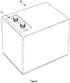
FIG. 2 shows an example embodiment of an audio playback device, here embodied as a speaker; -
FIG. 3A is a front view of a user interface arrangement in accordance with an embodiment; -
FIG. 3B is another front view of the user interface arrangement ofFIG. 3A ; -
FIG. 3C is a side view of the user interface arrangement ofFIG. 3B ; -
FIG. 4 shows one example implementation of an audio playback device comprising an embodiment of any of the user interface arrangements ofFIGS. 3A-3C ; and -
FIG. 5 shows another example implementation where a user interface panel comprises an embodiment of any of the user interface arrangements ofFIGS. 3A-3C . - The present invention will now be described more fully hereinafter. Like reference numbers refer to like elements throughout the description.
-
FIG. 1 shows anexample system configuration 1000, or example environment, in which one or more of the embodiments disclosed herein can be practiced or implemented. By way of illustration, thisexample system configuration 1000 represents a home with multiple zones. Each zone may, for example, represent a different room or space, such as an office, bathroom, bedroom, kitchen, dining room, family room, playroom, or laundry room. While not shown inFIG. 1 , a single zone can cover more than one room or space. One or more ofaudio playback devices audio playback device 1100A-1100n, also referred to as a multimedia playback device, speaker, and so on, provides audio and optionally also video and/or audiovisual output. As will be appreciated upon reading the present disclosure, one of theaudio playback devices 1100A-1100n (e.g., theaudio playback device 1100D in the family room) is configured to act as a master audio playback device. Accordingly, the remaining audio playback devices of theexample system configuration 1000 may be configured to act as slave audio playback devices. As will be appreciated, the master audio playback device is configured to act as a master and, accordingly, control the other audio playback devices (i.e., the slave audio playback devices). The audio playback device acting as the master hence provides control to thesystem configuration 1000. Thesystem configuration 1000 illustrates an example whole house audio system, though it is appreciated that the embodiments described herein are not limited to this particular application or to an expansive system like a wholehome audio system 1000 as schematically illustrated inFIG. 1 . -
FIG. 2 schematically illustrates an example embodiment of the present invention. Anaudio playback device 500, here exemplified as a speaker, comprises auser interface arrangement 100.FIG. 3A schematically illustrates one example embodiment of the user interface arrangement shown inFIG. 2 .FIGs 3B and 3C schematically illustrate first andsecond knobs 110A, 100B, respectively, of theuser interface arrangement 100.FIG. 3A is a front view of the first andsecond knobs FIG. 3B is a side view of the first andsecond knobs audio playback device 500 shown inFIG. 2 is configured to act as a master audio playback device in a system of audio playback devices including the masteraudio playback device 500 and several slave audio playback devices (seeFIG. 1 ), all of which are configured to be controlled by the masteraudio playback device 500. - With continued reference to
FIG. 2 andFIGs 3A-3C , an exampleuser interface arrangement 100 for controlling multiple functions of one or several audio playback devices will be described in further detail. - The first rotatable knob 100A has a first rotational axis A1 (see
FIG. 3C ) extending in a first axial direction. The first rotatable knob 100A is rotatable around this first rotational axis A1 to control a first function. The first function is a volume function. For example, rotating the firstrotatable knob 110A clockwise may increase the volume and rotating the firstrotatable knob 110A counter-clockwise may decrease the volume. In some embodiments, theuser interface arrangement 100 may comprise avisual indication 120. For example, thevisual indication 120 may comprise a textual information "- " and/or "+" to indicate the rotational directions of decreasing/increasing the volume. - The first rotatable knob 100A is additionally configured to be displaced axially in the first axial direction of the first rotational axis A1 to control a second function. Advantageously, the second function includes a selection function to select between two playback modes. A first playback mode may include playing audio at one single audio playback device. Typically, but not necessarily, this single audio playback device is the master
audio playback device 500 itself. The first playback mode may hence be referred to as "Solo". Furthermore, a second playback mode may include playing audio at several audio playback devices. The second playback mode may hence be referred to as "Multi". As will be appreciated, by pressing/depressing the firstrotatable knob 110A, it is made possible for the user to switch between the two playback modes "Solo" and "Multi", respectively. When in "Solo" mode, a rotation of the firstrotatable knob 110A may control the volume of theaudio playback device 500 individually. When in "Multi" mode, a rotation of the firstrotatable knob 110A may e.g. control the volume of theaudio playback device 500 itself as well as the volume of one or several (e.g., all) connected audio playback devices of a system of audio playback devices. - In some embodiments, the
user interface arrangement 100 may comprise avisual indication 120. For example, thevisual indication 120 may comprise a textual information "SOLO" and/or "MULTI" to indicate the earlier-mentioned playback modes. Also, the textual information (i.e., "SOLO" and/or "MULTI") may be accompanied with a visual indicator, here exemplified by Light Emitting Diodes (LEDs). In one example, thevisual indication 120 is configured to give visual indications of detected events occurring in theaudio playback device 500 as a prompt for potential human interaction with theuser interface arrangement 100. - A second
rotatable knob 110B is also provided at theuser interface arrangement 100. The secondrotatable knob 110B has a second rotational axis A2 (seeFIG. 3C ) that extends in a second axial direction. The secondrotatable knob 110B is rotatable around the second rotational axis A2 to control a third function. This third function includes a selection function to select a media source (e.g., audio source) of the media (e.g., audio) to be played. Furthermore, the secondrotatable knob 110B is additionally configured to be displaced axially in said second axial direction of the second rotational axis A2 to control a fourth function. The fourth function includes function which is dependent on a current setting (or, selection) of the third function. For example, the secondrotatable knob 110B may be rotated clockwise (or, counter-clockwise) to select, or choose, a certain audio source (e.g., channel "1") and by subsequently pressing (i.e., displacing) the secondrotatable knob 110B it is made possible for the user to activate the thus made choice/selection of the audio source (e.g.,channel 1 in this example). - In the embodiment schematically illustrated in
FIG. 3A , there are ten possible selections (or, selectable options), here exemplified by numbers 1-7, AUX, BLUETOOTH, and CLOUD. As can be seen inFig. 3A , theuser interface arrangement 100 may comprise avisual indication 140. For example, thevisual indication 140 may comprise textual information to indicate the earlier-mentioned selection possibilities 1-7, AUX, BLUETOOTH, and CLOUD. Also, the textual information (i.e., 1-7, AUX, BLUETOOTH, and CLOUD) may be accompanied with a respective visual indicator, here exemplified by Light Emitting Diodes (LEDs). The behavior of the LEDs in order to give the user appropriate visual indications of detected selections, e.g. as a prompt for potential human interaction with theuser interface arrangement 100, may be varied in many ways. For example, in one embodiment, when a user selects a new source by turning the secondrotatable knob 110B, the selected source may be indicated by a dimmed light of the accompanying LED. The LED indicating the currently playing source may still have a steady light. For instance, not until the new source has been activated (by pressing the secondrotatable knob 110B) the LED light will then be steady and the previous source LED light will be turned off. As will be appreciated, the LED behavior may be varied in many ways depending on user demands and other possible system requirements. - In the embodiment illustrated in
FIG. 3A , the selectable options are: - AUX
- Bluetooth
- Cloud (e.g., streamed content (such as audio) over a networks, e.g. Spotify® or Internet Radio)
- Preset 1-7
- These channels, or options, may be pre-set by the user. Hence, the user may for example assign favorite playlists (e.g., playlists of Spotify® or channels of Internet Radio) to each one of the seven pre-set channels. In some embodiments, the pre-set channels may be automatically configured by the audio playback device the first time the user uses the audio play back device. For example, the pre-sets could be auto-generated on the basis of which audio the user usually listens to.
- In some embodiments, the displacement of the second
rotatable knob 110B may have different functionality depending on which option of the ten selectable options that has been selected. For example, in one example embodiment, theuser interface arrangement 100 may be pre-configured with the following functionality: - AUX - short press to select source.
- Bluetooth - short press to select source and to set the
audio playback device 500 into pairing mode. Once activated/connected, short press plays or pauses the current audio. Double press to skip audio song. Triple press to play previous song. Long press to set Bluetooth into discoverable mode. - Cloud - short press to activate. Once activated short press plays or pauses the current audio. Double press to skip song. Triple press to play previous song. Long press to set speaker into wifi-setup mode.
- Preset 1-7 - short press to activate the selected preset option. Once activated short press plays or pauses the current audio. Double press to skip song. Triple press to play previous song. It might also be possible to save the currently playing audio on one of the desired presets 1-7 by a long press.
- As can be seen in
FIG. 3A , theuser interface arrangement 100 may optionally also includetextual information 150 to indicate the brand, or trademark, of theaudio playback device 500. In this example, the brand name is URBANEARS™ which is a brand of the applicant of the present patent application. - Reference is now made to
FIG. 4 , which schematically illustrates one example embodiment of theaudio playback device 500 shown inFIG. 2 . Theaudio playback device 500 is preferably, though not necessarily, a speaker. In this example embodiment, theaudio playback device 500 comprises one ormore processors 200 and one ormore memories 300. Also, acommunications interface 400, or a communications circuitry, is provided in order to allow theaudio playback device 500 to communicate with other audio playback devices, electronic devices and/or servers and/or media presentation systems, e.g. via a network (such as the Internet). To this end, thecommunications interface 400 may comprise a transmitter (Tx) and a receiver (Rx). Alternatively, thecommunications interface 400 may comprise a transceiver (Tx/Rx) combining both transmission and reception capabilities. Thecommunications interface 400 may include a radio frequency (RF) interface allowing theaudio playback device 500 to communicate with other audio playback devices, electronic devices and/or servers and/or media presentation systems through a radio frequency band through the use of different radio frequency technologies such as LTE (Long Term Evolution), WCDMA (Wideband Code Division Multiple Access), any other cellular network standardized by the 3rd Generation Partnership Project (3GPP), or any other wireless technology such as Wi-Fi, Bluetooth®, etcetera. Theaudio playback device 500 also comprises theuser interface arrangement 100 as described earlier in this disclosure. Theaudio interface arrangement 100 is operatively connected to the one ormore processors 200. The one ormore processors 200 are operatively connected to the one ormore memories 300. The one or more memories comprise(s) instructions which are executable by the one ormore processors 200. - According to this example embodiment, a rotation of the first
rotatable knob 110A around the first rotational axis A1 causes a first signal to be transmitted to the processor(s) 200 for controlling the earlier-mentioned first function. Furthermore, an axial displacement of the firstrotatable knob 110A in said first axial direction causes a second signal to be transmitted to the processor(s) 200 for controlling the earlier-mentioned second function. Moreover, a rotation of the secondrotatable knob 110B around the second rotational axis A2 causes a third signal to be transmitted to the processor(s) 200 for controlling the earlier-mentioned third function. Still further, an axial displacement of the secondrotatable knob 110B in said second axial direction causes a fourth signal to be transmitted to the processor(s) 200 for controlling said fourth function. - The
user interface arrangement 100 of theaudio playback device 500 contains tworotatable knobs user interface arrangement 100 has more than one but less than three rotatable knobs. - By providing a
user interface arrangement 100 comprising first and secondrotatable knobs - As will be appreciated, it is not necessary that the
user interface arrangement 100 is part of anaudio playback device 500, such as a speaker. - In alternative embodiments, such as the example embodiment schematically illustrated in
FIG. 5 , auser interface panel 600 comprises theuser interface arrangement 100. Theuser interface panel 600 may be attachable to house equipment, such as a housing wall. This way, it is made possible for a user to control multiple functions of an individualaudio playback device 500 or several audio playback devices by interaction with the tworotatable knobs 110A, 100B of theuser interface arrangement 100 of saiduser interface panel 600. - In other non-claimed embodiments, it is possible to complement the
audio playback device 500 ofFIGs 2-4 with a remote control of theaudio playback device 500. To this end, a method of remotely controlling theaudio playback device 500 may be provided, although no methods form part of the appended claims. The method may be performed by an electronic device (not shown), such as a mobile telephone (e.g., a smart phone) or a tablet computer, having one or more processors and memory storing one or more programs for execution by the one or more processors. For example, the one or more programs may include instructions that when executed by the one or more processors control the operation of the electronic device. For example, upon execution of said instructions by the one or more processors, this may cause the electronic device to remotely control functions that are controllable by means of theuser interface arrangement 100 of the audio playback device. - The present disclosure has presented various embodiments for multi-function control of one or several multimedia playback devices, such as speakers (e.g., wifi-connected speakers). By providing a
user interface arrangement 100 having first and second rotatable knobs 100A, 100B as described hereinabove it is made possible to collaboratively control a plurality of functions at one single audio playback device or at several audio playback devices. It is made possible to control many different functions of the one or several audio playback devices by using only two rotatable knobs. Few components are hence needed to enable the multi-function control of the audio playback device(s). This contributes to a solution for controlling various functions of a multimedia playback system (e.g., a home music system) that is intuitive, easy-to-use and/or non-complex.
Claims (4)
- An audio playback device (500) comprising a user interface arrangement (100) configured to control multiple functions of one or several audio playback devices in a networked audio playback system of audio playback devices, such as a home audio system, the user interface arrangement (100) comprising:a first rotatable knob (110A) having a first rotational axis (A1) extending in a first axial direction, wherein the first rotatable knob (110A) is rotatable around said first rotational axis (A1) to control a first function which includes a volume function and wherein the first rotatable knob (110A) is further configured to be displaced axially in said first axial direction of the first rotational axis (A1) to control a second function which includes a selection function to select between two playback modes; anda second rotatable knob (110B) having a second rotational axis (A2) extending in a second axial direction, wherein the second rotatable knob (110B) is rotatable around said second rotational axis (A2) to control a third function which includes a selection function to select an audio source of the audio to be played and wherein the second rotatable knob (110B) is further configured to be displaced axially in said second axial direction of the second rotational axis (A2) to control a fourth function which includes a function which is dependent on a current setting of the third function,characterized in thata first playback mode of said playback modes includes playing audio at one single audio playback device of the networked audio playback system of audio playback devices and wherein a second playback mode of said playback modes includes playing audio at several audio playback devices of the networked audio playback system of audio playback devices.
- The audio playback device (500) according to claim 1, wherein the user interface arrangement (100) is operatively connected to a processor (200), and wherein the processor (200) is operatively connected to:a memory (300) comprising instructions which are executable by said processor (200); anda communications interface (400) configured for wired or wireless communication with one or several audio playback devices; whereina rotation of the first rotatable knob (110A) around the first rotational axis (A1) causes a first signal to be transmitted to the processor (200) for controlling said first function;an axial displacement of the first rotatable knob (110A) in said first axial direction causes a second signal to be transmitted to the processor (200) for controlling said second function;a rotation of the second rotatable knob (110B) around the second rotational axis (A2) causes a third signal to be transmitted to the processor (200) for controlling said third function; andan axial displacement of the second rotatable knob (110B) in said second axial direction causes a fourth signal to be transmitted to the processor (200) for controlling said fourth function.
- The audio playback device (500) according to claim 1 or 2, wherein the audio playback device (500) is a master audio playback device in said networked audio playback system of audio playback devices, the networked audio playback system of audio playback devices including the master audio playback device (500) and several slave audio playback devices, all of which are configured to be controlled by the master audio playback device (500).
- The audio playback device (500) according to any of the preceding claims, wherein the audio playback device (500) is a speaker.
Applications Claiming Priority (2)
| Application Number | Priority Date | Filing Date | Title |
|---|---|---|---|
| US201562271978P | 2015-12-28 | 2015-12-28 | |
| PCT/EP2016/080612 WO2017114650A1 (en) | 2015-12-28 | 2016-12-12 | Multi-function control of one or several multimedia playback devices |
Publications (2)
| Publication Number | Publication Date |
|---|---|
| EP3398348A1 EP3398348A1 (en) | 2018-11-07 |
| EP3398348B1 true EP3398348B1 (en) | 2021-01-20 |
Family
ID=57708549
Family Applications (1)
| Application Number | Title | Priority Date | Filing Date |
|---|---|---|---|
| EP16820189.5A Not-in-force EP3398348B1 (en) | 2015-12-28 | 2016-12-12 | Multi-function control of one or several multimedia playback devices |
Country Status (4)
| Country | Link |
|---|---|
| US (1) | US10531182B2 (en) |
| EP (1) | EP3398348B1 (en) |
| CN (1) | CN108370461B (en) |
| WO (1) | WO2017114650A1 (en) |
Families Citing this family (5)
| Publication number | Priority date | Publication date | Assignee | Title |
|---|---|---|---|---|
| SE543016C2 (en) | 2017-09-14 | 2020-09-29 | Zound Industries Int Ab | A detachable knob for controlling a function of a loudspeaker |
| CN109032560A (en) * | 2018-07-26 | 2018-12-18 | 歌尔股份有限公司 | A kind of parameter adjusting method based on rotary encoder, device and electronic equipment |
| US11393478B2 (en) | 2018-12-12 | 2022-07-19 | Sonos, Inc. | User specific context switching |
| CN119225678A (en) * | 2023-06-30 | 2024-12-31 | 合肥美的洗衣机有限公司 | Method, device and readable storage medium for playing prompt sound of household appliance knob |
| GB2700309A (en) * | 2024-04-05 | 2026-01-14 | Menani Meriem | Shushiie audio device |
Citations (7)
| Publication number | Priority date | Publication date | Assignee | Title |
|---|---|---|---|---|
| US6438241B1 (en) * | 1998-02-23 | 2002-08-20 | Euphonix, Inc. | Multiple driver rotary control for audio processors or other uses |
| US20030209411A1 (en) * | 2002-05-10 | 2003-11-13 | Mcgrath James H. | Rear mounted integrated rotary encoder including a pushbutton switch |
| EP1585015A1 (en) * | 2004-03-17 | 2005-10-12 | 3DConnexion GmbH | User interface device |
| US20130022221A1 (en) * | 2011-07-19 | 2013-01-24 | Christopher Kallai | Shaping sound responsive to speaker orientation |
| US20130249814A1 (en) * | 2012-03-26 | 2013-09-26 | Peng Zeng | Adjustment Mechanisms For Virtual Knobs On A Touchscreen Interface |
| US8796566B2 (en) * | 2012-02-28 | 2014-08-05 | Grayhill, Inc. | Rotary pushbutton and touchpad device and system and method for detecting rotary movement, axial displacement and touchpad gestures |
| EP3125649A1 (en) * | 2014-03-28 | 2017-02-01 | CCS Inc. | Lighting control power supply |
Family Cites Families (15)
| Publication number | Priority date | Publication date | Assignee | Title |
|---|---|---|---|---|
| US5825308A (en) * | 1996-11-26 | 1998-10-20 | Immersion Human Interface Corporation | Force feedback interface having isotonic and isometric functionality |
| US6154201A (en) | 1996-11-26 | 2000-11-28 | Immersion Corporation | Control knob with multiple degrees of freedom and force feedback |
| US6225980B1 (en) | 1998-02-06 | 2001-05-01 | Carnegie Mellon University | Multi-functional, rotary dial input device for portable computers |
| JP2000149720A (en) | 1998-11-06 | 2000-05-30 | Teikoku Tsushin Kogyo Co Ltd | Rotary electronic components with pushbutton switches |
| US6741273B1 (en) | 1999-08-04 | 2004-05-25 | Mitsubishi Electric Research Laboratories Inc | Video camera controlled surround sound |
| GB0008916D0 (en) | 2000-04-11 | 2000-05-31 | Flux Research Pty Ltd | Control apparatus |
| JP4577063B2 (en) * | 2005-03-29 | 2010-11-10 | ヤマハ株式会社 | Operation detection device for operation element in acoustic control device |
| US20070087686A1 (en) * | 2005-10-18 | 2007-04-19 | Nokia Corporation | Audio playback device and method of its operation |
| US7223926B1 (en) | 2006-07-13 | 2007-05-29 | Harris Corporation | Knob assembly for operating the switch of a radio |
| CN101681663B (en) | 2007-05-22 | 2013-10-16 | 皇家飞利浦电子股份有限公司 | A device for and a method of processing audio data |
| US7592562B1 (en) | 2008-10-31 | 2009-09-22 | Harris Corporation | Knob assembly |
| US8971546B2 (en) | 2011-10-14 | 2015-03-03 | Sonos, Inc. | Systems, methods, apparatus, and articles of manufacture to control audio playback devices |
| CN104160720A (en) | 2012-01-09 | 2014-11-19 | 伊美神公司 | Wireless audio player and speaker system |
| CN103686262A (en) * | 2012-08-30 | 2014-03-26 | 珠海扬智电子科技有限公司 | Multimedia player device, system and remote control device thereof |
| KR20150120120A (en) | 2014-04-17 | 2015-10-27 | 삼성전자주식회사 | Rotary knob assembly capable of moving up and down |
-
2016
- 2016-12-12 WO PCT/EP2016/080612 patent/WO2017114650A1/en not_active Ceased
- 2016-12-12 CN CN201680076544.3A patent/CN108370461B/en not_active Expired - Fee Related
- 2016-12-12 EP EP16820189.5A patent/EP3398348B1/en not_active Not-in-force
- 2016-12-12 US US16/061,607 patent/US10531182B2/en active Active
Patent Citations (7)
| Publication number | Priority date | Publication date | Assignee | Title |
|---|---|---|---|---|
| US6438241B1 (en) * | 1998-02-23 | 2002-08-20 | Euphonix, Inc. | Multiple driver rotary control for audio processors or other uses |
| US20030209411A1 (en) * | 2002-05-10 | 2003-11-13 | Mcgrath James H. | Rear mounted integrated rotary encoder including a pushbutton switch |
| EP1585015A1 (en) * | 2004-03-17 | 2005-10-12 | 3DConnexion GmbH | User interface device |
| US20130022221A1 (en) * | 2011-07-19 | 2013-01-24 | Christopher Kallai | Shaping sound responsive to speaker orientation |
| US8796566B2 (en) * | 2012-02-28 | 2014-08-05 | Grayhill, Inc. | Rotary pushbutton and touchpad device and system and method for detecting rotary movement, axial displacement and touchpad gestures |
| US20130249814A1 (en) * | 2012-03-26 | 2013-09-26 | Peng Zeng | Adjustment Mechanisms For Virtual Knobs On A Touchscreen Interface |
| EP3125649A1 (en) * | 2014-03-28 | 2017-02-01 | CCS Inc. | Lighting control power supply |
Also Published As
| Publication number | Publication date |
|---|---|
| US20180359557A1 (en) | 2018-12-13 |
| US10531182B2 (en) | 2020-01-07 |
| EP3398348A1 (en) | 2018-11-07 |
| WO2017114650A1 (en) | 2017-07-06 |
| CN108370461A (en) | 2018-08-03 |
| CN108370461B (en) | 2020-07-10 |
Similar Documents
| Publication | Publication Date | Title |
|---|---|---|
| US11758327B2 (en) | Playback device pairing | |
| US10966025B2 (en) | Playback device pairing | |
| CN106664496B (en) | wireless speaker system | |
| US11184721B2 (en) | Playback device control | |
| CA3032479C (en) | Multi-channel pairing in a media system | |
| CN107103921B (en) | Method, device and apparatus for operating a playback device and media playback system | |
| US10531182B2 (en) | Multi-function control of one or several multimedia playback devices | |
| GB2460219A (en) | Interaction between Audio/Visual Display Appliances and Mobile Devices | |
| US9967667B2 (en) | Method and system for audio broadcast using lighting devices | |
| US12167216B2 (en) | Playback device pairing |
Legal Events
| Date | Code | Title | Description |
|---|---|---|---|
| STAA | Information on the status of an ep patent application or granted ep patent |
Free format text: STATUS: UNKNOWN |
|
| STAA | Information on the status of an ep patent application or granted ep patent |
Free format text: STATUS: THE INTERNATIONAL PUBLICATION HAS BEEN MADE |
|
| PUAI | Public reference made under article 153(3) epc to a published international application that has entered the european phase |
Free format text: ORIGINAL CODE: 0009012 |
|
| STAA | Information on the status of an ep patent application or granted ep patent |
Free format text: STATUS: REQUEST FOR EXAMINATION WAS MADE |
|
| 17P | Request for examination filed |
Effective date: 20180529 |
|
| AK | Designated contracting states |
Kind code of ref document: A1 Designated state(s): AL AT BE BG CH CY CZ DE DK EE ES FI FR GB GR HR HU IE IS IT LI LT LU LV MC MK MT NL NO PL PT RO RS SE SI SK SM TR |
|
| AX | Request for extension of the european patent |
Extension state: BA ME |
|
| DAV | Request for validation of the european patent (deleted) | ||
| DAX | Request for extension of the european patent (deleted) | ||
| STAA | Information on the status of an ep patent application or granted ep patent |
Free format text: STATUS: EXAMINATION IS IN PROGRESS |
|
| 17Q | First examination report despatched |
Effective date: 20190524 |
|
| GRAP | Despatch of communication of intention to grant a patent |
Free format text: ORIGINAL CODE: EPIDOSNIGR1 |
|
| STAA | Information on the status of an ep patent application or granted ep patent |
Free format text: STATUS: GRANT OF PATENT IS INTENDED |
|
| INTG | Intention to grant announced |
Effective date: 20200724 |
|
| GRAS | Grant fee paid |
Free format text: ORIGINAL CODE: EPIDOSNIGR3 |
|
| GRAA | (expected) grant |
Free format text: ORIGINAL CODE: 0009210 |
|
| STAA | Information on the status of an ep patent application or granted ep patent |
Free format text: STATUS: THE PATENT HAS BEEN GRANTED |
|
| AK | Designated contracting states |
Kind code of ref document: B1 Designated state(s): AL AT BE BG CH CY CZ DE DK EE ES FI FR GB GR HR HU IE IS IT LI LT LU LV MC MK MT NL NO PL PT RO RS SE SI SK SM TR |
|
| REG | Reference to a national code |
Ref country code: GB Ref legal event code: FG4D |
|
| REG | Reference to a national code |
Ref country code: CH Ref legal event code: EP |
|
| REG | Reference to a national code |
Ref country code: SE Ref legal event code: TRGR |
|
| REG | Reference to a national code |
Ref country code: DE Ref legal event code: R096 Ref document number: 602016051795 Country of ref document: DE |
|
| REG | Reference to a national code |
Ref country code: AT Ref legal event code: REF Ref document number: 1357379 Country of ref document: AT Kind code of ref document: T Effective date: 20210215 |
|
| REG | Reference to a national code |
Ref country code: IE Ref legal event code: FG4D |
|
| REG | Reference to a national code |
Ref country code: NL Ref legal event code: MP Effective date: 20210120 |
|
| REG | Reference to a national code |
Ref country code: LT Ref legal event code: MG9D |
|
| REG | Reference to a national code |
Ref country code: AT Ref legal event code: MK05 Ref document number: 1357379 Country of ref document: AT Kind code of ref document: T Effective date: 20210120 |
|
| PG25 | Lapsed in a contracting state [announced via postgrant information from national office to epo] |
Ref country code: FI Free format text: LAPSE BECAUSE OF FAILURE TO SUBMIT A TRANSLATION OF THE DESCRIPTION OR TO PAY THE FEE WITHIN THE PRESCRIBED TIME-LIMIT Effective date: 20210120 Ref country code: GR Free format text: LAPSE BECAUSE OF FAILURE TO SUBMIT A TRANSLATION OF THE DESCRIPTION OR TO PAY THE FEE WITHIN THE PRESCRIBED TIME-LIMIT Effective date: 20210421 Ref country code: HR Free format text: LAPSE BECAUSE OF FAILURE TO SUBMIT A TRANSLATION OF THE DESCRIPTION OR TO PAY THE FEE WITHIN THE PRESCRIBED TIME-LIMIT Effective date: 20210120 Ref country code: PT Free format text: LAPSE BECAUSE OF FAILURE TO SUBMIT A TRANSLATION OF THE DESCRIPTION OR TO PAY THE FEE WITHIN THE PRESCRIBED TIME-LIMIT Effective date: 20210520 Ref country code: NO Free format text: LAPSE BECAUSE OF FAILURE TO SUBMIT A TRANSLATION OF THE DESCRIPTION OR TO PAY THE FEE WITHIN THE PRESCRIBED TIME-LIMIT Effective date: 20210420 Ref country code: LT Free format text: LAPSE BECAUSE OF FAILURE TO SUBMIT A TRANSLATION OF THE DESCRIPTION OR TO PAY THE FEE WITHIN THE PRESCRIBED TIME-LIMIT Effective date: 20210120 Ref country code: BG Free format text: LAPSE BECAUSE OF FAILURE TO SUBMIT A TRANSLATION OF THE DESCRIPTION OR TO PAY THE FEE WITHIN THE PRESCRIBED TIME-LIMIT Effective date: 20210420 |
|
| PG25 | Lapsed in a contracting state [announced via postgrant information from national office to epo] |
Ref country code: AT Free format text: LAPSE BECAUSE OF FAILURE TO SUBMIT A TRANSLATION OF THE DESCRIPTION OR TO PAY THE FEE WITHIN THE PRESCRIBED TIME-LIMIT Effective date: 20210120 Ref country code: LV Free format text: LAPSE BECAUSE OF FAILURE TO SUBMIT A TRANSLATION OF THE DESCRIPTION OR TO PAY THE FEE WITHIN THE PRESCRIBED TIME-LIMIT Effective date: 20210120 Ref country code: PL Free format text: LAPSE BECAUSE OF FAILURE TO SUBMIT A TRANSLATION OF THE DESCRIPTION OR TO PAY THE FEE WITHIN THE PRESCRIBED TIME-LIMIT Effective date: 20210120 Ref country code: RS Free format text: LAPSE BECAUSE OF FAILURE TO SUBMIT A TRANSLATION OF THE DESCRIPTION OR TO PAY THE FEE WITHIN THE PRESCRIBED TIME-LIMIT Effective date: 20210120 |
|
| PG25 | Lapsed in a contracting state [announced via postgrant information from national office to epo] |
Ref country code: IS Free format text: LAPSE BECAUSE OF FAILURE TO SUBMIT A TRANSLATION OF THE DESCRIPTION OR TO PAY THE FEE WITHIN THE PRESCRIBED TIME-LIMIT Effective date: 20210520 |
|
| REG | Reference to a national code |
Ref country code: DE Ref legal event code: R097 Ref document number: 602016051795 Country of ref document: DE |
|
| PG25 | Lapsed in a contracting state [announced via postgrant information from national office to epo] |
Ref country code: EE Free format text: LAPSE BECAUSE OF FAILURE TO SUBMIT A TRANSLATION OF THE DESCRIPTION OR TO PAY THE FEE WITHIN THE PRESCRIBED TIME-LIMIT Effective date: 20210120 Ref country code: CZ Free format text: LAPSE BECAUSE OF FAILURE TO SUBMIT A TRANSLATION OF THE DESCRIPTION OR TO PAY THE FEE WITHIN THE PRESCRIBED TIME-LIMIT Effective date: 20210120 Ref country code: SM Free format text: LAPSE BECAUSE OF FAILURE TO SUBMIT A TRANSLATION OF THE DESCRIPTION OR TO PAY THE FEE WITHIN THE PRESCRIBED TIME-LIMIT Effective date: 20210120 |
|
| PLBE | No opposition filed within time limit |
Free format text: ORIGINAL CODE: 0009261 |
|
| STAA | Information on the status of an ep patent application or granted ep patent |
Free format text: STATUS: NO OPPOSITION FILED WITHIN TIME LIMIT |
|
| PG25 | Lapsed in a contracting state [announced via postgrant information from national office to epo] |
Ref country code: SK Free format text: LAPSE BECAUSE OF FAILURE TO SUBMIT A TRANSLATION OF THE DESCRIPTION OR TO PAY THE FEE WITHIN THE PRESCRIBED TIME-LIMIT Effective date: 20210120 Ref country code: RO Free format text: LAPSE BECAUSE OF FAILURE TO SUBMIT A TRANSLATION OF THE DESCRIPTION OR TO PAY THE FEE WITHIN THE PRESCRIBED TIME-LIMIT Effective date: 20210120 Ref country code: DK Free format text: LAPSE BECAUSE OF FAILURE TO SUBMIT A TRANSLATION OF THE DESCRIPTION OR TO PAY THE FEE WITHIN THE PRESCRIBED TIME-LIMIT Effective date: 20210120 |
|
| 26N | No opposition filed |
Effective date: 20211021 |
|
| PG25 | Lapsed in a contracting state [announced via postgrant information from national office to epo] |
Ref country code: AL Free format text: LAPSE BECAUSE OF FAILURE TO SUBMIT A TRANSLATION OF THE DESCRIPTION OR TO PAY THE FEE WITHIN THE PRESCRIBED TIME-LIMIT Effective date: 20210120 Ref country code: ES Free format text: LAPSE BECAUSE OF FAILURE TO SUBMIT A TRANSLATION OF THE DESCRIPTION OR TO PAY THE FEE WITHIN THE PRESCRIBED TIME-LIMIT Effective date: 20210120 |
|
| PGFP | Annual fee paid to national office [announced via postgrant information from national office to epo] |
Ref country code: DE Payment date: 20211208 Year of fee payment: 6 Ref country code: GB Payment date: 20211207 Year of fee payment: 6 Ref country code: FR Payment date: 20211207 Year of fee payment: 6 Ref country code: SE Payment date: 20211208 Year of fee payment: 6 |
|
| PG25 | Lapsed in a contracting state [announced via postgrant information from national office to epo] |
Ref country code: SI Free format text: LAPSE BECAUSE OF FAILURE TO SUBMIT A TRANSLATION OF THE DESCRIPTION OR TO PAY THE FEE WITHIN THE PRESCRIBED TIME-LIMIT Effective date: 20210120 |
|
| PG25 | Lapsed in a contracting state [announced via postgrant information from national office to epo] |
Ref country code: IT Free format text: LAPSE BECAUSE OF FAILURE TO SUBMIT A TRANSLATION OF THE DESCRIPTION OR TO PAY THE FEE WITHIN THE PRESCRIBED TIME-LIMIT Effective date: 20210120 |
|
| PG25 | Lapsed in a contracting state [announced via postgrant information from national office to epo] |
Ref country code: IS Free format text: LAPSE BECAUSE OF FAILURE TO SUBMIT A TRANSLATION OF THE DESCRIPTION OR TO PAY THE FEE WITHIN THE PRESCRIBED TIME-LIMIT Effective date: 20210520 |
|
| PG25 | Lapsed in a contracting state [announced via postgrant information from national office to epo] |
Ref country code: MC Free format text: LAPSE BECAUSE OF FAILURE TO SUBMIT A TRANSLATION OF THE DESCRIPTION OR TO PAY THE FEE WITHIN THE PRESCRIBED TIME-LIMIT Effective date: 20210120 |
|
| REG | Reference to a national code |
Ref country code: CH Ref legal event code: PL |
|
| REG | Reference to a national code |
Ref country code: BE Ref legal event code: MM Effective date: 20211231 |
|
| PG25 | Lapsed in a contracting state [announced via postgrant information from national office to epo] |
Ref country code: LU Free format text: LAPSE BECAUSE OF NON-PAYMENT OF DUE FEES Effective date: 20211212 Ref country code: IE Free format text: LAPSE BECAUSE OF NON-PAYMENT OF DUE FEES Effective date: 20211212 |
|
| PG25 | Lapsed in a contracting state [announced via postgrant information from national office to epo] |
Ref country code: BE Free format text: LAPSE BECAUSE OF NON-PAYMENT OF DUE FEES Effective date: 20211231 |
|
| PG25 | Lapsed in a contracting state [announced via postgrant information from national office to epo] |
Ref country code: LI Free format text: LAPSE BECAUSE OF NON-PAYMENT OF DUE FEES Effective date: 20211231 Ref country code: CH Free format text: LAPSE BECAUSE OF NON-PAYMENT OF DUE FEES Effective date: 20211231 |
|
| PG25 | Lapsed in a contracting state [announced via postgrant information from national office to epo] |
Ref country code: NL Free format text: LAPSE BECAUSE OF NON-PAYMENT OF DUE FEES Effective date: 20210120 Ref country code: CY Free format text: LAPSE BECAUSE OF FAILURE TO SUBMIT A TRANSLATION OF THE DESCRIPTION OR TO PAY THE FEE WITHIN THE PRESCRIBED TIME-LIMIT Effective date: 20210120 |
|
| REG | Reference to a national code |
Ref country code: DE Ref legal event code: R119 Ref document number: 602016051795 Country of ref document: DE |
|
| PG25 | Lapsed in a contracting state [announced via postgrant information from national office to epo] |
Ref country code: HU Free format text: LAPSE BECAUSE OF FAILURE TO SUBMIT A TRANSLATION OF THE DESCRIPTION OR TO PAY THE FEE WITHIN THE PRESCRIBED TIME-LIMIT; INVALID AB INITIO Effective date: 20161212 |
|
| REG | Reference to a national code |
Ref country code: SE Ref legal event code: EUG |
|
| GBPC | Gb: european patent ceased through non-payment of renewal fee |
Effective date: 20221212 |
|
| PG25 | Lapsed in a contracting state [announced via postgrant information from national office to epo] |
Ref country code: SE Free format text: LAPSE BECAUSE OF NON-PAYMENT OF DUE FEES Effective date: 20221213 Ref country code: GB Free format text: LAPSE BECAUSE OF NON-PAYMENT OF DUE FEES Effective date: 20221212 Ref country code: DE Free format text: LAPSE BECAUSE OF NON-PAYMENT OF DUE FEES Effective date: 20230701 |
|
| PG25 | Lapsed in a contracting state [announced via postgrant information from national office to epo] |
Ref country code: FR Free format text: LAPSE BECAUSE OF NON-PAYMENT OF DUE FEES Effective date: 20221231 |
|
| PG25 | Lapsed in a contracting state [announced via postgrant information from national office to epo] |
Ref country code: MK Free format text: LAPSE BECAUSE OF FAILURE TO SUBMIT A TRANSLATION OF THE DESCRIPTION OR TO PAY THE FEE WITHIN THE PRESCRIBED TIME-LIMIT Effective date: 20210120 |
|
| PG25 | Lapsed in a contracting state [announced via postgrant information from national office to epo] |
Ref country code: MT Free format text: LAPSE BECAUSE OF FAILURE TO SUBMIT A TRANSLATION OF THE DESCRIPTION OR TO PAY THE FEE WITHIN THE PRESCRIBED TIME-LIMIT Effective date: 20210120 |
|
| PG25 | Lapsed in a contracting state [announced via postgrant information from national office to epo] |
Ref country code: TR Free format text: LAPSE BECAUSE OF FAILURE TO SUBMIT A TRANSLATION OF THE DESCRIPTION OR TO PAY THE FEE WITHIN THE PRESCRIBED TIME-LIMIT Effective date: 20210120 |