EP3397849B1 - Method for constructing a mathematical model of a petrol fuel injector of a bi-fuel supply plant of a motor for a motor vehicle and electronic control board of the gas injectors usable in a bi-fuel supply plant of a motor for a motor vehicle - Google Patents
Method for constructing a mathematical model of a petrol fuel injector of a bi-fuel supply plant of a motor for a motor vehicle and electronic control board of the gas injectors usable in a bi-fuel supply plant of a motor for a motor vehicle Download PDFInfo
- Publication number
- EP3397849B1 EP3397849B1 EP16831750.1A EP16831750A EP3397849B1 EP 3397849 B1 EP3397849 B1 EP 3397849B1 EP 16831750 A EP16831750 A EP 16831750A EP 3397849 B1 EP3397849 B1 EP 3397849B1
- Authority
- EP
- European Patent Office
- Prior art keywords
- petrol
- motor
- flow rate
- injection duration
- gas
- Prior art date
- Legal status (The legal status is an assumption and is not a legal conclusion. Google has not performed a legal analysis and makes no representation as to the accuracy of the status listed.)
- Active
Links
Images

Classifications
-
- F—MECHANICAL ENGINEERING; LIGHTING; HEATING; WEAPONS; BLASTING
- F02—COMBUSTION ENGINES; HOT-GAS OR COMBUSTION-PRODUCT ENGINE PLANTS
- F02D—CONTROLLING COMBUSTION ENGINES
- F02D41/00—Electrical control of supply of combustible mixture or its constituents
- F02D41/0025—Controlling engines characterised by use of non-liquid fuels, pluralities of fuels, or non-fuel substances added to the combustible mixtures
-
- F—MECHANICAL ENGINEERING; LIGHTING; HEATING; WEAPONS; BLASTING
- F02—COMBUSTION ENGINES; HOT-GAS OR COMBUSTION-PRODUCT ENGINE PLANTS
- F02D—CONTROLLING COMBUSTION ENGINES
- F02D19/00—Controlling engines characterised by their use of non-liquid fuels, pluralities of fuels, or non-fuel substances added to the combustible mixtures
- F02D19/06—Controlling engines characterised by their use of non-liquid fuels, pluralities of fuels, or non-fuel substances added to the combustible mixtures peculiar to engines working with pluralities of fuels, e.g. alternatively with light and heavy fuel oil, other than engines indifferent to the fuel consumed
-
- F—MECHANICAL ENGINEERING; LIGHTING; HEATING; WEAPONS; BLASTING
- F02—COMBUSTION ENGINES; HOT-GAS OR COMBUSTION-PRODUCT ENGINE PLANTS
- F02D—CONTROLLING COMBUSTION ENGINES
- F02D19/00—Controlling engines characterised by their use of non-liquid fuels, pluralities of fuels, or non-fuel substances added to the combustible mixtures
- F02D19/06—Controlling engines characterised by their use of non-liquid fuels, pluralities of fuels, or non-fuel substances added to the combustible mixtures peculiar to engines working with pluralities of fuels, e.g. alternatively with light and heavy fuel oil, other than engines indifferent to the fuel consumed
- F02D19/0626—Measuring or estimating parameters related to the fuel supply system
-
- F—MECHANICAL ENGINEERING; LIGHTING; HEATING; WEAPONS; BLASTING
- F02—COMBUSTION ENGINES; HOT-GAS OR COMBUSTION-PRODUCT ENGINE PLANTS
- F02D—CONTROLLING COMBUSTION ENGINES
- F02D19/00—Controlling engines characterised by their use of non-liquid fuels, pluralities of fuels, or non-fuel substances added to the combustible mixtures
- F02D19/06—Controlling engines characterised by their use of non-liquid fuels, pluralities of fuels, or non-fuel substances added to the combustible mixtures peculiar to engines working with pluralities of fuels, e.g. alternatively with light and heavy fuel oil, other than engines indifferent to the fuel consumed
- F02D19/0626—Measuring or estimating parameters related to the fuel supply system
- F02D19/0628—Determining the fuel pressure, temperature or flow, the fuel tank fill level or a valve position
-
- F—MECHANICAL ENGINEERING; LIGHTING; HEATING; WEAPONS; BLASTING
- F02—COMBUSTION ENGINES; HOT-GAS OR COMBUSTION-PRODUCT ENGINE PLANTS
- F02D—CONTROLLING COMBUSTION ENGINES
- F02D19/00—Controlling engines characterised by their use of non-liquid fuels, pluralities of fuels, or non-fuel substances added to the combustible mixtures
- F02D19/06—Controlling engines characterised by their use of non-liquid fuels, pluralities of fuels, or non-fuel substances added to the combustible mixtures peculiar to engines working with pluralities of fuels, e.g. alternatively with light and heavy fuel oil, other than engines indifferent to the fuel consumed
- F02D19/0626—Measuring or estimating parameters related to the fuel supply system
- F02D19/0628—Determining the fuel pressure, temperature or flow, the fuel tank fill level or a valve position
- F02D19/0631—Determining the fuel pressure, temperature or flow, the fuel tank fill level or a valve position by estimation, i.e. without using direct measurements of a corresponding sensor
-
- F—MECHANICAL ENGINEERING; LIGHTING; HEATING; WEAPONS; BLASTING
- F02—COMBUSTION ENGINES; HOT-GAS OR COMBUSTION-PRODUCT ENGINE PLANTS
- F02D—CONTROLLING COMBUSTION ENGINES
- F02D19/00—Controlling engines characterised by their use of non-liquid fuels, pluralities of fuels, or non-fuel substances added to the combustible mixtures
- F02D19/06—Controlling engines characterised by their use of non-liquid fuels, pluralities of fuels, or non-fuel substances added to the combustible mixtures peculiar to engines working with pluralities of fuels, e.g. alternatively with light and heavy fuel oil, other than engines indifferent to the fuel consumed
- F02D19/0639—Controlling engines characterised by their use of non-liquid fuels, pluralities of fuels, or non-fuel substances added to the combustible mixtures peculiar to engines working with pluralities of fuels, e.g. alternatively with light and heavy fuel oil, other than engines indifferent to the fuel consumed characterised by the type of fuels
- F02D19/0642—Controlling engines characterised by their use of non-liquid fuels, pluralities of fuels, or non-fuel substances added to the combustible mixtures peculiar to engines working with pluralities of fuels, e.g. alternatively with light and heavy fuel oil, other than engines indifferent to the fuel consumed characterised by the type of fuels at least one fuel being gaseous, the other fuels being gaseous or liquid at standard conditions
-
- F—MECHANICAL ENGINEERING; LIGHTING; HEATING; WEAPONS; BLASTING
- F02—COMBUSTION ENGINES; HOT-GAS OR COMBUSTION-PRODUCT ENGINE PLANTS
- F02D—CONTROLLING COMBUSTION ENGINES
- F02D41/00—Electrical control of supply of combustible mixture or its constituents
- F02D41/0025—Controlling engines characterised by use of non-liquid fuels, pluralities of fuels, or non-fuel substances added to the combustible mixtures
- F02D41/0027—Controlling engines characterised by use of non-liquid fuels, pluralities of fuels, or non-fuel substances added to the combustible mixtures the fuel being gaseous
-
- F—MECHANICAL ENGINEERING; LIGHTING; HEATING; WEAPONS; BLASTING
- F02—COMBUSTION ENGINES; HOT-GAS OR COMBUSTION-PRODUCT ENGINE PLANTS
- F02D—CONTROLLING COMBUSTION ENGINES
- F02D41/00—Electrical control of supply of combustible mixture or its constituents
- F02D41/24—Electrical control of supply of combustible mixture or its constituents characterised by the use of digital means
- F02D41/2406—Electrical control of supply of combustible mixture or its constituents characterised by the use of digital means using essentially read only memories
- F02D41/2425—Particular ways of programming the data
- F02D41/2429—Methods of calibrating or learning
- F02D41/2451—Methods of calibrating or learning characterised by what is learned or calibrated
- F02D41/2464—Characteristics of actuators
- F02D41/2467—Characteristics of actuators for injectors
-
- F—MECHANICAL ENGINEERING; LIGHTING; HEATING; WEAPONS; BLASTING
- F02—COMBUSTION ENGINES; HOT-GAS OR COMBUSTION-PRODUCT ENGINE PLANTS
- F02D—CONTROLLING COMBUSTION ENGINES
- F02D41/00—Electrical control of supply of combustible mixture or its constituents
- F02D41/02—Circuit arrangements for generating control signals
- F02D41/14—Introducing closed-loop corrections
- F02D41/1401—Introducing closed-loop corrections characterised by the control or regulation method
- F02D2041/1433—Introducing closed-loop corrections characterised by the control or regulation method using a model or simulation of the system
-
- F—MECHANICAL ENGINEERING; LIGHTING; HEATING; WEAPONS; BLASTING
- F02—COMBUSTION ENGINES; HOT-GAS OR COMBUSTION-PRODUCT ENGINE PLANTS
- F02D—CONTROLLING COMBUSTION ENGINES
- F02D2200/00—Input parameters for engine control
- F02D2200/02—Input parameters for engine control the parameters being related to the engine
- F02D2200/06—Fuel or fuel supply system parameters
- F02D2200/0614—Actual fuel mass or fuel injection amount
- F02D2200/0616—Actual fuel mass or fuel injection amount determined by estimation
-
- F—MECHANICAL ENGINEERING; LIGHTING; HEATING; WEAPONS; BLASTING
- F02—COMBUSTION ENGINES; HOT-GAS OR COMBUSTION-PRODUCT ENGINE PLANTS
- F02D—CONTROLLING COMBUSTION ENGINES
- F02D2400/00—Control systems adapted for specific engine types; Special features of engine control systems not otherwise provided for; Power supply, connectors or cabling for engine control systems
- F02D2400/11—After-sales modification devices designed to be used to modify an engine afterwards
-
- F—MECHANICAL ENGINEERING; LIGHTING; HEATING; WEAPONS; BLASTING
- F02—COMBUSTION ENGINES; HOT-GAS OR COMBUSTION-PRODUCT ENGINE PLANTS
- F02D—CONTROLLING COMBUSTION ENGINES
- F02D41/00—Electrical control of supply of combustible mixture or its constituents
- F02D41/24—Electrical control of supply of combustible mixture or its constituents characterised by the use of digital means
- F02D41/26—Electrical control of supply of combustible mixture or its constituents characterised by the use of digital means using computer, e.g. microprocessor
- F02D41/266—Electrical control of supply of combustible mixture or its constituents characterised by the use of digital means using computer, e.g. microprocessor the computer being backed-up or assisted by another circuit, e.g. analogue
-
- Y—GENERAL TAGGING OF NEW TECHNOLOGICAL DEVELOPMENTS; GENERAL TAGGING OF CROSS-SECTIONAL TECHNOLOGIES SPANNING OVER SEVERAL SECTIONS OF THE IPC; TECHNICAL SUBJECTS COVERED BY FORMER USPC CROSS-REFERENCE ART COLLECTIONS [XRACs] AND DIGESTS
- Y02—TECHNOLOGIES OR APPLICATIONS FOR MITIGATION OR ADAPTATION AGAINST CLIMATE CHANGE
- Y02T—CLIMATE CHANGE MITIGATION TECHNOLOGIES RELATED TO TRANSPORTATION
- Y02T10/00—Road transport of goods or passengers
- Y02T10/10—Internal combustion engine [ICE] based vehicles
- Y02T10/30—Use of alternative fuels, e.g. biofuels
Definitions
- the present invention relates to a method for calibrating an electronic control board using a mathematical model of a petrol fuel injector of a bi-fuel supply plant of a motor for a motor vehicle, and an electronic control board of the gas injectors usable in a bi-fuel supply plant of a motor for a motor vehicle.
- the present invention has been developed for general use and, in particular, for use in the motor vehicle after-sales sector (known as the "aftermarket").
- the "petrol side” control board has a master function, so that in response to input motoring parameters, calculates the injection times and commands the corresponding petrol injectors for supplying the motor with a quantity of petrol such that the air-petrol mixture combustion ratio in the cylinders assumes a predetermined value, for example stoichiometric.
- the "gas side” (slave) control board drives the gas injectors with the aim of supplying the motor with a quantity of gas that is energetically equivalent.
- the plant is retro-activated due to the presence of a lambda probe, for the control of the air/fuel ratio. Given the intrinsic differences between the petrol injectors and the gas injectors, the energetic equivalence is established by means of appropriate correctors organised in "maps".
- the installer traditionally sets the various motoring parameters and compiles the carburetion maps for the various functioning points of the motor. This is a long and laborious operation. Further, as these operations are not always carried out on the motor bench, not all the working points of the motor can be tried out (both due to physical difficulties and for reasons of time), so that the maps present various boxes that are empty or completed by interpolation algorithms.
- the technical task objective at the base of the present invention relates to a method for calibrating an electronic control board using a mathematical model of a petrol fuel injector of a bi-fuel supply plant of a motor for a motor vehicle, and an electronic control board of the gas injectors usable in a bi-fuel supply plant of a motor for a motor vehicle, which obviate the drawbacks in the above-mentioned prior art.
- an aim of the present invention is to provide a method for calibrating an electronic control board using a mathematical model of a petrol fuel injector of a bi-fuel supply plant of a motor for a motor vehicle, which is more rapid, precise and reliable than known methods.
- a further aim of the present invention relates to a method for calibrating an electronic control board using a mathematical model of a petrol fuel injector of a bi-fuel supply plant of a motor for a motor vehicle, and an electronic control board of the gas injectors usable in a bi-fuel supply plant of a motor for a motor vehicle, usable in motor vehicle after-sales.
- reference numeral 1 denotes a bi-fuel supply plant for a motor M for a motor vehicle.
- the bi-fuel supply plant is in itself of known type. In this context, for simplicity of description reference is made to a bi-fuel supply plant 1 comprising the following essential elements:
- the characteristic curve of the gas injectors I G is known.
- the petrol injector I B is characterisable by means of a flow rate curve Q B as a function of the injection duration t B , having a progression as illustrated in figure 3 .
- p B is taken to be the injection pressure value of the petrol from which the pressure value p MAP has already been subtracted, i.e.
- the coefficient K representing the geometry and the intercept at the origin t OFF . are not known.
- the method for calibrating an electronic control board using a mathematical model of a petrol injector I B i.e the method for determining the curve Q B (T B ) for the petrol injector I B , is described in the following.
- the engine (M) is supplied with petrol.
- the motor M is taken into a first stable working condition to which corresponds a first value of a ratio A characteristic of carburetion.
- the ratio A characteristic of the carburetion is the ratio between the air quantity actually requested for combustion with respect to the theoretical air requirement.
- the motor M is preferably at a minimum working regime without loads.
- the injection pressure p B1 is detected as well as and the injection duration t B1 of the petrol injector I B .
- the supply is switched from petrol to gas.
- the motor M In the second working condition the motor M is preferably working at a minimum working regime with a plurality of active loads (for example, air-conditioning, headlights, fans, windscreen wipers, etc.). Alternatively, in the second working condition the motor M is in a loaded condition due to the movement of the motor vehicle. In the second working condition, the injection pressure p B2 is detected as well as and the injection duration t B2 of the petrol injector I B . Maintaining the second working condition of the motor, the gas supply is newly switched from petrol to gas. This determines an imbalance in carburetion.
- active loads for example, air-conditioning, headlights, fans, windscreen wipers, etc.
- the injection duration t G of said gas injector I G is varied up to reaching a first injection duration t G2 such that the characteristic ratio A of the carburetion newly assumes the second value.
- the second value for the ratio ⁇ a situation is thus reached in which the rapid correctors do not intervene.
- the flow rate value of dispensed gas Q G2 corresponding to the second injection duration tG2 is determined. It is therefore possible to calculate the flow rate Q B2 of the second working condition as a function of the energetic equivalence of the flow rate of dispensed gas Q G2 at the second injection duration t G2 of the gas injector I G .
- a second point P 2 of the characteristic curve of the flow rate Q B of the petrol injector I B has been obtained, the x-axis whereof is represented by the injection duration t B2 previously detected and the y-axis whereof is represented by the flow rate of petrol Q B2 just calculated.
- the two unknown factors can be calculated, i.e. the coefficient K representing the geometry and the intercept at the origin t OFF .
- the distance between the first point P 1 and the second point P 2 should preferably be the same as or greater than a minimum value.
- the second working condition is modified up to reaching (or exceeding) the minimum distance value between the two points P 1 , P 2 .
- the relative interval ⁇ tB between the injection duration t B2 in the second condition and the injection duration t B1 in the first working condition is calculated.
- the relative interval ⁇ tB is lower than a predefined threshold ⁇ tBmin , the following steps are cyclically carried out in chronological order:
Landscapes
- Engineering & Computer Science (AREA)
- Chemical & Material Sciences (AREA)
- Combustion & Propulsion (AREA)
- Mechanical Engineering (AREA)
- General Engineering & Computer Science (AREA)
- Oil, Petroleum & Natural Gas (AREA)
- Electrical Control Of Air Or Fuel Supplied To Internal-Combustion Engine (AREA)
- Output Control And Ontrol Of Special Type Engine (AREA)
Description
- The present invention relates to a method for calibrating an electronic control board using a mathematical model of a petrol fuel injector of a bi-fuel supply plant of a motor for a motor vehicle, and an electronic control board of the gas injectors usable in a bi-fuel supply plant of a motor for a motor vehicle.
The present invention has been developed for general use and, in particular, for use in the motor vehicle after-sales sector (known as the "aftermarket"). - As is known, in a bi-fuel supply plant two control boards are present: one for the "petrol side" and the other for the "gas side".
In particular, the "petrol side" control board has a master function, so that in response to input motoring parameters, calculates the injection times and commands the corresponding petrol injectors for supplying the motor with a quantity of petrol such that the air-petrol mixture combustion ratio in the cylinders assumes a predetermined value, for example stoichiometric. On the other hand, the "gas side" (slave) control board drives the gas injectors with the aim of supplying the motor with a quantity of gas that is energetically equivalent.
The plant is retro-activated due to the presence of a lambda probe, for the control of the air/fuel ratio.
Given the intrinsic differences between the petrol injectors and the gas injectors, the energetic equivalence is established by means of appropriate correctors organised in "maps". - The installer traditionally sets the various motoring parameters and compiles the carburetion maps for the various functioning points of the motor. This is a long and laborious operation.
Further, as these operations are not always carried out on the motor bench, not all the working points of the motor can be tried out (both due to physical difficulties and for reasons of time), so that the maps present various boxes that are empty or completed by interpolation algorithms. - In this context, the technical task objective at the base of the present invention relates to a method for calibrating an electronic control board using a mathematical model of a petrol fuel injector of a bi-fuel supply plant of a motor for a motor vehicle, and an electronic control board of the gas injectors usable in a bi-fuel supply plant of a motor for a motor vehicle, which obviate the drawbacks in the above-mentioned prior art.
In particular, an aim of the present invention is to provide a method for calibrating an electronic control board using a mathematical model of a petrol fuel injector of a bi-fuel supply plant of a motor for a motor vehicle, which is more rapid, precise and reliable than known methods.
A further aim of the present invention relates to a method for calibrating an electronic control board using a mathematical model of a petrol fuel injector of a bi-fuel supply plant of a motor for a motor vehicle, and an electronic control board of the gas injectors usable in a bi-fuel supply plant of a motor for a motor vehicle, usable in motor vehicle after-sales. - Additional features and advantages of the present invention will become more apparent from the indicative and thus non-limiting description of a preferred but not exclusive embodiment of a method for calibrating an electronic control board using a mathematical model of a petrol fuel injector of a bi-fuel supply plant of a motor for a motor vehicle and an electronic control board of the gas injectors in a bi-fuel supply plant of a motor for a motor vehicle, as illustrated in the appended drawings, in which:
-
figure 1 illustrates the simplified diagram of a bi-fuel supply plant of a motor for a motor vehicle; -
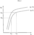
figure 2 illustrates characteristic curves of the flow rate of the gas as a function of the injection duration of the gas; -
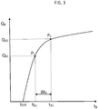
figure 3 illustrates a characteristic curve of the flow rate of the petrol as a function of the injection duration of the petrol. - With reference to the figures, reference numeral 1 denotes a bi-fuel supply plant for a motor M for a motor vehicle.
The bi-fuel supply plant is in itself of known type.
In this context, for simplicity of description reference is made to a bi-fuel supply plant 1 comprising the following essential elements: - a plurality of petrol injectors IB;
- a control board CB of the petrol injectors IB;
- a plurality of gas injectors IG;
- a control board CG of the gas injectors IG;
- a switching unit S comprising a switch for switching supply to the cylinders of the motor M from petrol to gas and vice versa.
- In this context, it is assumed that the characteristic curve of the gas injectors IG is known.
Likewise, the petrol injector IB is characterisable by means of a flow rate curve QB as a function of the injection duration tB, having a progression as illustrated infigure 3 .
In particular, the flow rate QB of the petrol is linked to the injection duration tB by the following formula:
In this context, pB is taken to be the injection pressure value of the petrol from which the pressure value pMAP has already been subtracted, i.e. the absolute pressure value present in the aspirating manifold of the motor M. In this context, for the petrol injector IB the coefficient K representing the geometry and the intercept at the origin tOFF. are not known.
The method for calibrating an electronic control board using a mathematical model of a petrol injector IB, i.e the method for determining the curve QB(TB) for the petrol injector IB, is described in the following.
First of all, the engine (M) is supplied with petrol.
The motor M is taken into a first stable working condition to which corresponds a first value of a ratio A characteristic of carburetion.
In particular, the ratio A characteristic of the carburetion is the ratio between the air quantity actually requested for combustion with respect to the theoretical air requirement.
In the first working condition the motor M is preferably at a minimum working regime without loads.
In the first working condition, the injection pressure pB1 is detected as well as and the injection duration tB1 of the petrol injector IB.
While maintaining the first working condition, the supply is switched from petrol to gas. - This determines an imbalance in carburetion. To return to the balanced condition, the injection duration tG of said gas injector IG is varied up to reaching a first injection duration tG1 such that the characteristic ratio A of the carburetion newly assumes the first value.
On reaching the first value for the ratio λ, a situation is thus reached in which it is not required for the rapid correctors to intervene.
By knowing the characteristic curve of the gas injector IG, the flow rate of dispensed gas QG1 corresponding to the first injection duration tG1 is determined.
It is therefore possible to calculate the flow rate of petrol QB1 relative to the first working condition as a function of the energetic equivalence of the flow rate of dispensed gas QG1 at the first injection duration tG1 of the gas injector IG.
Thus a first point P1 of the characteristic curve of the flow rate QB of the petrol injector IB has been obtained, the x-axis whereof is represented by the injection duration tB1 previously detected and the y-axis whereof is represented by the flow rate of petrol QB1 just calculated.
With the first point P1 defined, the gas supply is newly switched from gas to petrol.
The motor M is taken into a second stable working condition to which corresponds a second value of the ratio A characteristic of carburetion.
In the second working condition the motor M is preferably working at a minimum working regime with a plurality of active loads (for example, air-conditioning, headlights, fans, windscreen wipers, etc.).
Alternatively, in the second working condition the motor M is in a loaded condition due to the movement of the motor vehicle.
In the second working condition, the injection pressure pB2 is detected as well as and the injection duration tB2 of the petrol injector IB.
Maintaining the second working condition of the motor, the gas supply is newly switched from petrol to gas.
This determines an imbalance in carburetion. To return to the balanced condition, the injection duration tG of said gas injector IG is varied up to reaching a first injection duration tG2 such that the characteristic ratio A of the carburetion newly assumes the second value.
On reaching the second value for the ratio λ, a situation is thus reached in which the rapid correctors do not intervene.
By knowing the characteristic curve of the gas injector IG, the flow rate value of dispensed gas QG2 corresponding to the second injection duration tG2 is determined.
It is therefore possible to calculate the flow rate QB2 of the second working condition as a function of the energetic equivalence of the flow rate of dispensed gas QG2 at the second injection duration tG2 of the gas injector IG.
Thus a second point P2 of the characteristic curve of the flow rate QB of the petrol injector IB has been obtained, the x-axis whereof is represented by the injection duration tB2 previously detected and the y-axis whereof is represented by the flow rate of petrol QB2 just calculated.
With two points P1, P2 of the characteristic curve of the flow rate QB of the petrol injector IB known, the two unknown factors can be calculated, i.e. the coefficient K representing the geometry and the intercept at the origin tOFF.
The distance between the first point P1 and the second point P2 should preferably be the same as or greater than a minimum value. Vice versa, should the distance be less than a minimum value, the second working condition is modified up to reaching (or exceeding) the minimum distance value between the two points P1, P2.
In particular, after having detected the injection duration tB2 of said petrol injector IB in the second working condition, the relative interval ΔtB between the injection duration tB2 in the second condition and the injection duration tB1 in the first working condition is calculated.
As long as the relative interval ΔtB is lower than a predefined threshold ΔtBmin, the following steps are cyclically carried out in chronological order: - modifying the second working condition of the motor M;
- detecting the injection duration tB2 of the petrol injector IB in the second working condition of the motor M;
- calculating the relative interval ΔtB between the injection duration tB2 in the second condition and the injection duration tB1 in the first working condition.
- In particular, in order to construct the mathematical model of the petrol fuel injector it is sufficient to set two stable working conditions of the motor. The method is therefore simple, reliable, rapid and can easily be used in any workshop (after-market applications).
Further, should it be desired to improve the precision of the characteristic curve of the petrol injectors, it is possible to set further stable working conditions of the motor.
Each gas injector IG is characterised, for a predetermined pair of pressure p and temperature T values, by a curve of the flow rate QG as a function of the injection duration tG.
For example, in
The control board CG of the gas injectors IG is configured for determining the characteristic curve of the flow rate QB of a petrol injector IB using the above-described method.
After having characterised the petrol injector IB, the control board CG of the gas injectors IG is able to determine the gas flow rate QG to be supplied to the motor M.
In particular, during the functioning of the motor M with gas supply, the injection duration (tB) of the petrol injectors IB is detected.
With the duration known, the petrol flow rate QB and therefore, as a function of the energy equivalence, the gas flow rate QB to be dispensed are calculated.
Once the petrol fuel injector IB has been characterised, the initial self-calibration of the plant 1 can be proceeded. It is further possible to include a periodic calibration during the driving of the vehicle.
From the description provided the characteristics of a method for calibrating an electronic control board using a mathematical model of a petrol fuel injector of a bi-fuel supply plant of a motor for a motor vehicle emerge clearly, as well as those of an electronic control board of the gas injectors usable in a bi-fuel supply plant of a motor for a motor vehicle, according to the present invention, as are the resulting advantages thereof.
Claims (5)
- Method for calibrating an electronic control board (CG) using a mathematical model of a petrol fuel injector (IB) of a bi-fuel supply plant of a motor (M) for a motor vehicle, said mathematical model being defined by a characteristic curve of a flow rate (QB) of the petrol as a function of an injection duration (tB) of the petrol expressed by the relation
 supplying the engine (M) with petrol;taking the motor (M) into a first stable working condition to which corresponds a first value of a ratio (λ) characteristic of carburetion;detecting the injection pressure (pB1) and the injection duration (tB1) of said petrol injector (IB) in said first working condition of the motor (M);maintaining the first working condition of the motor (M), switching the supply of petrol to gas by means of a gas injector (IG) of which a characteristic curve of the flow rate (QG) is known as a function of an injection duration (tG);varying the injection duration (tG) of said gas injector (IG) up to reaching a first injection duration (tG1) such that the characteristic ratio (λ) of the carburetion assumes said first value;determining the flow rate of dispensed gas (QG1) corresponding to said first injection duration (tG1);calculating the flow rate of petrol (QB1) relative to said first working condition as a function of an energetic equivalence of the flow rate of dispensed gas (QG1) in said first injection duration (tG1) of the gas injector (IG), the injection duration (tB1) and the flow rate of petrol (QB1) relative to said first working condition respectively representing the x-axis and the y-axis of a first point (P1) of the characteristic curve of the flow rate (QB) of the petrol injector (IB);newly switching the gas supply to petrol;taking the motor (M) into a second stable working condition to which corresponds a second value of said characteristic ratio (λ) of carburetion;detecting the injection pressure (pB2) and the injection duration (tB2) of said petrol injector (IB) in said second working condition of the motor (M);maintaining the second working condition of the motor (M), newly switching the supply from petrol to gas;varying the injection duration (tG) of said gas injector (IG) up to reaching a second injection duration (tG2) such that the characteristic ratio (λ) of the carburetion assumes said second value;determining the flow rate of dispensed gas (QG2) corresponding to said second injection duration (tG2);calculating the flow rate of petrol (QB2) relative to said second working condition as a function of an energetic equivalence of the flow rate of dispensed gas (QG2) in said second injection duration (tG2) of the gas injector (IG), the injection duration (tB2) and the flow rate of petrol (QB2) relative to said second working condition respectively representing the x-axis and the y-axis of a second point (P2) of the characteristic curve of the flow rate (QB) of the petrol injector (IB);determining the representative coefficient (K) of the geometry of said petrol injector (IB) and the intercept at the origin (tOFF) starting from the injection pressure values (pB1, pB2) and the injection duration (tB1, tB2) detected respectively in the first and the second working conditions and from the petrol flow rate values (QB1, QB2) calculated in said two same working conditions of the motor (M).
 - Method according to claim 1, further comprising the following steps:after having detected the injection duration (tB2) of said petrol injector (tB) in the second working condition of the motor (M), calculating the relative interval (ΔtB) between the injection duration (tB2) in said second condition and the injection duration (tB1) in the first working condition;as long as the relative interval (ΔtB) is lower than a predefined threshold (ΔtBmin), cyclically carrying out following steps in chronological order:modifying the second working condition of the motor (M);detecting the injection duration (tB2) of said petrol injector (IB) in said second working condition of the motor (M);calculating the relative interval (ΔtB) between the injection duration (tB2) in the second condition and the injection duration (tB1) in the first working condition;
- Method according to any one of the preceding claims, wherein in said first working condition the motor (M) is at a minimum working regime without loads and in said second working condition the motor (M) is working at a minimum working regime with a plurality of loads in activity.
- Electronic control board (CG) of the gas injectors (IG) usable in a bi-fuel supply plant of a motor (M) for a motor vehicle, said control board (CG) being configured for:determining the characteristic curve of the flow rate (QB) of a petrol injector (IB) using the method according to one of claims from 1 to 3;detecting the injection pressure (tB) of petrol injectors (IB) during the functioning of the motor (M) with a gas supply;using said characteristic curve of the flow rate (QB) of a petrol injector (IB) for calculating an equivalent petrol flow rate (QB) as a function of the injection duration (tB) detected of petrol injectors (IB);calculating the gas flow rate (QG) to be dispensed as a function of the energy equivalence of said petrol flow rate (QB);supplying the calculated gas flow rate (QG).
- Computer program product directly loadable in a memory of a control board (CG) of gas injectors (IG) of a bi-fuel supply plant, said computer program product comprising instructions which, when the program is executed by the control board (CG) of claim 4 cause said control board (CG) to carry out the method according to claims from 1 to 3.
Applications Claiming Priority (2)
| Application Number | Priority Date | Filing Date | Title |
|---|---|---|---|
| ITUB2015A009514A ITUB20159514A1 (en) | 2015-12-28 | 2015-12-28 | METHOD OF CONSTRUCTION OF A MATHEMATICAL MODEL OF A GASOLINE INJECTOR OF A BI-FUEL SUPPLY SYSTEM OF A MOTOR FOR MOTOR VEHICLES AND CONTROL UNITS FOR GAS INJECTORS THAT CAN BE USED IN A BI-FUEL SUPPLY SYSTEM FOR A MOTOR FOR A MOTOR VEHICLE. |
| PCT/IB2016/057867 WO2017115228A1 (en) | 2015-12-28 | 2016-12-21 | Method for constructing a mathematical model of a petrol fuel injector of a bi-fuel supply plant of a motor for a motor vehicle and electronic control board of the gas injectors usable in a bi-fuel supply plant of a motor for a motor vehicle |
Publications (2)
| Publication Number | Publication Date |
|---|---|
| EP3397849A1 EP3397849A1 (en) | 2018-11-07 |
| EP3397849B1 true EP3397849B1 (en) | 2020-03-25 |
Family
ID=55697395
Family Applications (1)
| Application Number | Title | Priority Date | Filing Date |
|---|---|---|---|
| EP16831750.1A Active EP3397849B1 (en) | 2015-12-28 | 2016-12-21 | Method for constructing a mathematical model of a petrol fuel injector of a bi-fuel supply plant of a motor for a motor vehicle and electronic control board of the gas injectors usable in a bi-fuel supply plant of a motor for a motor vehicle |
Country Status (4)
| Country | Link |
|---|---|
| EP (1) | EP3397849B1 (en) |
| CN (1) | CN108474313B (en) |
| IT (1) | ITUB20159514A1 (en) |
| WO (1) | WO2017115228A1 (en) |
Cited By (1)
| Publication number | Priority date | Publication date | Assignee | Title |
|---|---|---|---|---|
| US12085216B2 (en) | 2022-02-17 | 2024-09-10 | Arctic Cat Inc. | Multi-use fuel filler tube |
Families Citing this family (1)
| Publication number | Priority date | Publication date | Assignee | Title |
|---|---|---|---|---|
| IT201700092799A1 (en) * | 2017-08-10 | 2019-02-10 | Ekin S R L | Electronic control unit for vehicles converted to LPG, CNG or hydrogen |
Family Cites Families (8)
| Publication number | Priority date | Publication date | Assignee | Title |
|---|---|---|---|---|
| DE102006010632A1 (en) * | 2006-03-08 | 2007-09-13 | Iav Gmbh Ingenieurgesellschaft Auto Und Verkehr | Injection method for injecting fuel and water into a combustion chamber on an internal combustion engine injects fuel just once while relying on an operating point to inject water repeatedly |
| DE102006043243A1 (en) * | 2006-09-11 | 2008-03-27 | Schröder, Matthias | Alternative fuel e.g. methane, quantity estimating method, involves collecting injection period of base fuel, pressure and temperature alternative fuels, and determining energy equivalents between base and alternative fuels by adjusting box |
| JP4835716B2 (en) * | 2009-03-25 | 2011-12-14 | 株式会社デンソー | Fuel injection state detection device |
| JP4835715B2 (en) * | 2009-03-25 | 2011-12-14 | 株式会社デンソー | Fuel injection state detection device |
| DE102009053423A1 (en) * | 2009-11-19 | 2011-05-26 | Fev Motorentechnik Gmbh | Method and device for injecting an alternative fuel |
| KR101139179B1 (en) * | 2010-07-02 | 2012-04-26 | 현대중공업 주식회사 | Dual fuel injector valve with pumping nozzle for diesel and gas engine |
| CN202926466U (en) * | 2012-08-10 | 2013-05-08 | 恒力实业有限公司 | Petrol and natural gas dual fuel 4 cylinder engine |
| CA2894291C (en) * | 2015-06-12 | 2016-08-02 | Westport Power Inc. | Fuel injector trimming in a multi-fuel engine |
-
2015
- 2015-12-28 IT ITUB2015A009514A patent/ITUB20159514A1/en unknown
-
2016
- 2016-12-21 EP EP16831750.1A patent/EP3397849B1/en active Active
- 2016-12-21 CN CN201680076153.1A patent/CN108474313B/en active Active
- 2016-12-21 WO PCT/IB2016/057867 patent/WO2017115228A1/en not_active Ceased
Non-Patent Citations (1)
| Title |
|---|
| None * |
Cited By (1)
| Publication number | Priority date | Publication date | Assignee | Title |
|---|---|---|---|---|
| US12085216B2 (en) | 2022-02-17 | 2024-09-10 | Arctic Cat Inc. | Multi-use fuel filler tube |
Also Published As
| Publication number | Publication date |
|---|---|
| CN108474313B (en) | 2021-04-27 |
| CN108474313A (en) | 2018-08-31 |
| WO2017115228A1 (en) | 2017-07-06 |
| EP3397849A1 (en) | 2018-11-07 |
| ITUB20159514A1 (en) | 2017-06-28 |
Similar Documents
| Publication | Publication Date | Title |
|---|---|---|
| JP5543134B2 (en) | Method and controller for calibrating a fuel injector of an internal combustion engine, program and storage medium | |
| US20130340716A1 (en) | Closed loop control fuel injection method | |
| JPH0826805B2 (en) | Air-fuel ratio learning controller for internal combustion engine | |
| CN102053147A (en) | Method for determining proportion of heavier diesel component in diluted engine oil | |
| JPWO2011132464A1 (en) | Intake parameter calculation device and intake parameter calculation method for internal combustion engine | |
| US8756986B2 (en) | Method for operating an internal combustion engine | |
| US8775058B2 (en) | Method for the injector-individual adaption of the injection time of motor vehicles | |
| CN101213358B (en) | Method and controller for metering fuel to a combustion chamber of an internal combustion engine | |
| CN104632446A (en) | A method for detecting a deviation of an actual injection amount from a target fuel injection amount of an injector in an internal combustion engine | |
| JP2011510225A (en) | Internal combustion engine control method, apparatus, and program | |
| JP2011252418A (en) | Fuel injection system for internal combustion engine | |
| JP2010533817A (en) | Method and apparatus for determining fuel injection quantity for pre-injection | |
| WO2017115228A1 (en) | Method for constructing a mathematical model of a petrol fuel injector of a bi-fuel supply plant of a motor for a motor vehicle and electronic control board of the gas injectors usable in a bi-fuel supply plant of a motor for a motor vehicle | |
| US8903629B2 (en) | Method for adapting a fuel/air mixture for an internal combustion engine | |
| US9803579B2 (en) | Method for adapting a common-rail injection system of an internal combustion engine | |
| US8650011B2 (en) | Method for determining an engine response characteristic | |
| US10247126B2 (en) | Feedback control method for a fuel delivery system | |
| JP2009276091A (en) | Detecting device of residual quantity of fuel | |
| US20140121950A1 (en) | Method for operating an internal combustion engine having a plurality of cylinders in homogeneous operation | |
| JP2009121315A (en) | Control device for internal combustion engine | |
| EP2098709B1 (en) | A method for operating an internal combustion engine | |
| KR101752341B1 (en) | Apparatus and method for controlling of exhaust system temperature in internal combustion engine | |
| CN105275647B (en) | Method and apparatus for identifying air and fuel deviations | |
| JP6414421B2 (en) | Fuel injection control device for internal combustion engine | |
| KR102370967B1 (en) | Optimal operating line control method of HEV |
Legal Events
| Date | Code | Title | Description |
|---|---|---|---|
| STAA | Information on the status of an ep patent application or granted ep patent |
Free format text: STATUS: UNKNOWN |
|
| STAA | Information on the status of an ep patent application or granted ep patent |
Free format text: STATUS: THE INTERNATIONAL PUBLICATION HAS BEEN MADE |
|
| PUAI | Public reference made under article 153(3) epc to a published international application that has entered the european phase |
Free format text: ORIGINAL CODE: 0009012 |
|
| STAA | Information on the status of an ep patent application or granted ep patent |
Free format text: STATUS: REQUEST FOR EXAMINATION WAS MADE |
|
| 17P | Request for examination filed |
Effective date: 20180524 |
|
| AK | Designated contracting states |
Kind code of ref document: A1 Designated state(s): AL AT BE BG CH CY CZ DE DK EE ES FI FR GB GR HR HU IE IS IT LI LT LU LV MC MK MT NL NO PL PT RO RS SE SI SK SM TR |
|
| AX | Request for extension of the european patent |
Extension state: BA ME |
|
| DAV | Request for validation of the european patent (deleted) | ||
| DAX | Request for extension of the european patent (deleted) | ||
| STAA | Information on the status of an ep patent application or granted ep patent |
Free format text: STATUS: EXAMINATION IS IN PROGRESS |
|
| 17Q | First examination report despatched |
Effective date: 20190731 |
|
| GRAP | Despatch of communication of intention to grant a patent |
Free format text: ORIGINAL CODE: EPIDOSNIGR1 |
|
| STAA | Information on the status of an ep patent application or granted ep patent |
Free format text: STATUS: GRANT OF PATENT IS INTENDED |
|
| RIC1 | Information provided on ipc code assigned before grant |
Ipc: F02D 19/06 20060101ALI20191030BHEP Ipc: F02D 41/14 20060101ALI20191030BHEP Ipc: F02D 41/26 20060101ALI20191030BHEP Ipc: F02D 41/24 20060101AFI20191030BHEP Ipc: F02D 41/00 20060101ALI20191030BHEP |
|
| INTG | Intention to grant announced |
Effective date: 20191120 |
|
| GRAS | Grant fee paid |
Free format text: ORIGINAL CODE: EPIDOSNIGR3 |
|
| GRAA | (expected) grant |
Free format text: ORIGINAL CODE: 0009210 |
|
| STAA | Information on the status of an ep patent application or granted ep patent |
Free format text: STATUS: THE PATENT HAS BEEN GRANTED |
|
| AK | Designated contracting states |
Kind code of ref document: B1 Designated state(s): AL AT BE BG CH CY CZ DE DK EE ES FI FR GB GR HR HU IE IS IT LI LT LU LV MC MK MT NL NO PL PT RO RS SE SI SK SM TR |
|
| REG | Reference to a national code |
Ref country code: GB Ref legal event code: FG4D |
|
| REG | Reference to a national code |
Ref country code: AT Ref legal event code: REF Ref document number: 1248822 Country of ref document: AT Kind code of ref document: T Effective date: 20200415 Ref country code: IE Ref legal event code: FG4D |
|
| REG | Reference to a national code |
Ref country code: DE Ref legal event code: R096 Ref document number: 602016032708 Country of ref document: DE |
|
| REG | Reference to a national code |
Ref country code: NL Ref legal event code: FP |
|
| PG25 | Lapsed in a contracting state [announced via postgrant information from national office to epo] |
Ref country code: RS Free format text: LAPSE BECAUSE OF FAILURE TO SUBMIT A TRANSLATION OF THE DESCRIPTION OR TO PAY THE FEE WITHIN THE PRESCRIBED TIME-LIMIT Effective date: 20200325 Ref country code: FI Free format text: LAPSE BECAUSE OF FAILURE TO SUBMIT A TRANSLATION OF THE DESCRIPTION OR TO PAY THE FEE WITHIN THE PRESCRIBED TIME-LIMIT Effective date: 20200325 Ref country code: NO Free format text: LAPSE BECAUSE OF FAILURE TO SUBMIT A TRANSLATION OF THE DESCRIPTION OR TO PAY THE FEE WITHIN THE PRESCRIBED TIME-LIMIT Effective date: 20200625 |
|
| PG25 | Lapsed in a contracting state [announced via postgrant information from national office to epo] |
Ref country code: HR Free format text: LAPSE BECAUSE OF FAILURE TO SUBMIT A TRANSLATION OF THE DESCRIPTION OR TO PAY THE FEE WITHIN THE PRESCRIBED TIME-LIMIT Effective date: 20200325 Ref country code: LV Free format text: LAPSE BECAUSE OF FAILURE TO SUBMIT A TRANSLATION OF THE DESCRIPTION OR TO PAY THE FEE WITHIN THE PRESCRIBED TIME-LIMIT Effective date: 20200325 Ref country code: BG Free format text: LAPSE BECAUSE OF FAILURE TO SUBMIT A TRANSLATION OF THE DESCRIPTION OR TO PAY THE FEE WITHIN THE PRESCRIBED TIME-LIMIT Effective date: 20200625 Ref country code: SE Free format text: LAPSE BECAUSE OF FAILURE TO SUBMIT A TRANSLATION OF THE DESCRIPTION OR TO PAY THE FEE WITHIN THE PRESCRIBED TIME-LIMIT Effective date: 20200325 Ref country code: GR Free format text: LAPSE BECAUSE OF FAILURE TO SUBMIT A TRANSLATION OF THE DESCRIPTION OR TO PAY THE FEE WITHIN THE PRESCRIBED TIME-LIMIT Effective date: 20200626 |
|
| REG | Reference to a national code |
Ref country code: LT Ref legal event code: MG4D |
|
| PG25 | Lapsed in a contracting state [announced via postgrant information from national office to epo] |
Ref country code: CZ Free format text: LAPSE BECAUSE OF FAILURE TO SUBMIT A TRANSLATION OF THE DESCRIPTION OR TO PAY THE FEE WITHIN THE PRESCRIBED TIME-LIMIT Effective date: 20200325 Ref country code: RO Free format text: LAPSE BECAUSE OF FAILURE TO SUBMIT A TRANSLATION OF THE DESCRIPTION OR TO PAY THE FEE WITHIN THE PRESCRIBED TIME-LIMIT Effective date: 20200325 Ref country code: LT Free format text: LAPSE BECAUSE OF FAILURE TO SUBMIT A TRANSLATION OF THE DESCRIPTION OR TO PAY THE FEE WITHIN THE PRESCRIBED TIME-LIMIT Effective date: 20200325 Ref country code: SM Free format text: LAPSE BECAUSE OF FAILURE TO SUBMIT A TRANSLATION OF THE DESCRIPTION OR TO PAY THE FEE WITHIN THE PRESCRIBED TIME-LIMIT Effective date: 20200325 Ref country code: EE Free format text: LAPSE BECAUSE OF FAILURE TO SUBMIT A TRANSLATION OF THE DESCRIPTION OR TO PAY THE FEE WITHIN THE PRESCRIBED TIME-LIMIT Effective date: 20200325 Ref country code: SK Free format text: LAPSE BECAUSE OF FAILURE TO SUBMIT A TRANSLATION OF THE DESCRIPTION OR TO PAY THE FEE WITHIN THE PRESCRIBED TIME-LIMIT Effective date: 20200325 Ref country code: IS Free format text: LAPSE BECAUSE OF FAILURE TO SUBMIT A TRANSLATION OF THE DESCRIPTION OR TO PAY THE FEE WITHIN THE PRESCRIBED TIME-LIMIT Effective date: 20200725 Ref country code: PT Free format text: LAPSE BECAUSE OF FAILURE TO SUBMIT A TRANSLATION OF THE DESCRIPTION OR TO PAY THE FEE WITHIN THE PRESCRIBED TIME-LIMIT Effective date: 20200818 |
|
| REG | Reference to a national code |
Ref country code: AT Ref legal event code: MK05 Ref document number: 1248822 Country of ref document: AT Kind code of ref document: T Effective date: 20200325 |
|
| REG | Reference to a national code |
Ref country code: DE Ref legal event code: R097 Ref document number: 602016032708 Country of ref document: DE |
|
| PG25 | Lapsed in a contracting state [announced via postgrant information from national office to epo] |
Ref country code: AT Free format text: LAPSE BECAUSE OF FAILURE TO SUBMIT A TRANSLATION OF THE DESCRIPTION OR TO PAY THE FEE WITHIN THE PRESCRIBED TIME-LIMIT Effective date: 20200325 Ref country code: ES Free format text: LAPSE BECAUSE OF FAILURE TO SUBMIT A TRANSLATION OF THE DESCRIPTION OR TO PAY THE FEE WITHIN THE PRESCRIBED TIME-LIMIT Effective date: 20200325 Ref country code: DK Free format text: LAPSE BECAUSE OF FAILURE TO SUBMIT A TRANSLATION OF THE DESCRIPTION OR TO PAY THE FEE WITHIN THE PRESCRIBED TIME-LIMIT Effective date: 20200325 |
|
| PLBE | No opposition filed within time limit |
Free format text: ORIGINAL CODE: 0009261 |
|
| STAA | Information on the status of an ep patent application or granted ep patent |
Free format text: STATUS: NO OPPOSITION FILED WITHIN TIME LIMIT |
|
| PG25 | Lapsed in a contracting state [announced via postgrant information from national office to epo] |
Ref country code: PL Free format text: LAPSE BECAUSE OF FAILURE TO SUBMIT A TRANSLATION OF THE DESCRIPTION OR TO PAY THE FEE WITHIN THE PRESCRIBED TIME-LIMIT Effective date: 20200325 |
|
| 26N | No opposition filed |
Effective date: 20210112 |
|
| PG25 | Lapsed in a contracting state [announced via postgrant information from national office to epo] |
Ref country code: SI Free format text: LAPSE BECAUSE OF FAILURE TO SUBMIT A TRANSLATION OF THE DESCRIPTION OR TO PAY THE FEE WITHIN THE PRESCRIBED TIME-LIMIT Effective date: 20200325 |
|
| REG | Reference to a national code |
Ref country code: DE Ref legal event code: R119 Ref document number: 602016032708 Country of ref document: DE |
|
| REG | Reference to a national code |
Ref country code: CH Ref legal event code: PL |
|
| GBPC | Gb: european patent ceased through non-payment of renewal fee |
Effective date: 20201221 |
|
| PG25 | Lapsed in a contracting state [announced via postgrant information from national office to epo] |
Ref country code: MC Free format text: LAPSE BECAUSE OF FAILURE TO SUBMIT A TRANSLATION OF THE DESCRIPTION OR TO PAY THE FEE WITHIN THE PRESCRIBED TIME-LIMIT Effective date: 20200325 |
|
| REG | Reference to a national code |
Ref country code: BE Ref legal event code: MM Effective date: 20201231 |
|
| PG25 | Lapsed in a contracting state [announced via postgrant information from national office to epo] |
Ref country code: FR Free format text: LAPSE BECAUSE OF NON-PAYMENT OF DUE FEES Effective date: 20201231 Ref country code: LU Free format text: LAPSE BECAUSE OF NON-PAYMENT OF DUE FEES Effective date: 20201221 Ref country code: IE Free format text: LAPSE BECAUSE OF NON-PAYMENT OF DUE FEES Effective date: 20201221 |
|
| PG25 | Lapsed in a contracting state [announced via postgrant information from national office to epo] |
Ref country code: GB Free format text: LAPSE BECAUSE OF NON-PAYMENT OF DUE FEES Effective date: 20201221 Ref country code: LI Free format text: LAPSE BECAUSE OF NON-PAYMENT OF DUE FEES Effective date: 20201231 Ref country code: CH Free format text: LAPSE BECAUSE OF NON-PAYMENT OF DUE FEES Effective date: 20201231 Ref country code: DE Free format text: LAPSE BECAUSE OF NON-PAYMENT OF DUE FEES Effective date: 20210701 |
|
| PG25 | Lapsed in a contracting state [announced via postgrant information from national office to epo] |
Ref country code: MT Free format text: LAPSE BECAUSE OF FAILURE TO SUBMIT A TRANSLATION OF THE DESCRIPTION OR TO PAY THE FEE WITHIN THE PRESCRIBED TIME-LIMIT Effective date: 20200325 Ref country code: CY Free format text: LAPSE BECAUSE OF FAILURE TO SUBMIT A TRANSLATION OF THE DESCRIPTION OR TO PAY THE FEE WITHIN THE PRESCRIBED TIME-LIMIT Effective date: 20200325 |
|
| PG25 | Lapsed in a contracting state [announced via postgrant information from national office to epo] |
Ref country code: MK Free format text: LAPSE BECAUSE OF FAILURE TO SUBMIT A TRANSLATION OF THE DESCRIPTION OR TO PAY THE FEE WITHIN THE PRESCRIBED TIME-LIMIT Effective date: 20200325 Ref country code: AL Free format text: LAPSE BECAUSE OF FAILURE TO SUBMIT A TRANSLATION OF THE DESCRIPTION OR TO PAY THE FEE WITHIN THE PRESCRIBED TIME-LIMIT Effective date: 20200325 |
|
| PG25 | Lapsed in a contracting state [announced via postgrant information from national office to epo] |
Ref country code: BE Free format text: LAPSE BECAUSE OF NON-PAYMENT OF DUE FEES Effective date: 20201231 |
|
| P01 | Opt-out of the competence of the unified patent court (upc) registered |
Effective date: 20230527 |
|
| PG25 | Lapsed in a contracting state [announced via postgrant information from national office to epo] |
Ref country code: IS Free format text: LAPSE BECAUSE OF NON-PAYMENT OF DUE FEES Effective date: 20200725 |
|
| PGFP | Annual fee paid to national office [announced via postgrant information from national office to epo] |
Ref country code: IT Payment date: 20251222 Year of fee payment: 10 |
|
| PGFP | Annual fee paid to national office [announced via postgrant information from national office to epo] |
Ref country code: NL Payment date: 20251222 Year of fee payment: 10 |
|
| PGFP | Annual fee paid to national office [announced via postgrant information from national office to epo] |
Ref country code: TR Payment date: 20251215 Year of fee payment: 10 |