EP3397828B1 - Security apparatus for portable electronic device - Google Patents
Security apparatus for portable electronic device Download PDFInfo
- Publication number
- EP3397828B1 EP3397828B1 EP17757063.7A EP17757063A EP3397828B1 EP 3397828 B1 EP3397828 B1 EP 3397828B1 EP 17757063 A EP17757063 A EP 17757063A EP 3397828 B1 EP3397828 B1 EP 3397828B1
- Authority
- EP
- European Patent Office
- Prior art keywords
- security apparatus
- cam member
- plunger
- fingers
- portable electronic
- Prior art date
- Legal status (The legal status is an assumption and is not a legal conclusion. Google has not performed a legal analysis and makes no representation as to the accuracy of the status listed.)
- Active
Links
Images


Classifications
-
- E—FIXED CONSTRUCTIONS
- E05—LOCKS; KEYS; WINDOW OR DOOR FITTINGS; SAFES
- E05B—LOCKS; ACCESSORIES THEREFOR; HANDCUFFS
- E05B73/00—Devices for locking portable objects against unauthorised removal; Miscellaneous locking devices
-
- E—FIXED CONSTRUCTIONS
- E05—LOCKS; KEYS; WINDOW OR DOOR FITTINGS; SAFES
- E05B—LOCKS; ACCESSORIES THEREFOR; HANDCUFFS
- E05B73/00—Devices for locking portable objects against unauthorised removal; Miscellaneous locking devices
- E05B73/0082—Devices for locking portable objects against unauthorised removal; Miscellaneous locking devices for office machines, e.g. PC's, portable computers, typewriters, calculators
-
- E—FIXED CONSTRUCTIONS
- E05—LOCKS; KEYS; WINDOW OR DOOR FITTINGS; SAFES
- E05B—LOCKS; ACCESSORIES THEREFOR; HANDCUFFS
- E05B27/00—Cylinder locks or other locks with tumbler pins or balls that are set by pushing the key in
- E05B27/0003—Details
-
- E—FIXED CONSTRUCTIONS
- E05—LOCKS; KEYS; WINDOW OR DOOR FITTINGS; SAFES
- E05B—LOCKS; ACCESSORIES THEREFOR; HANDCUFFS
- E05B73/00—Devices for locking portable objects against unauthorised removal; Miscellaneous locking devices
- E05B73/0005—Devices for locking portable objects against unauthorised removal; Miscellaneous locking devices using chains, cables or the like
-
- G—PHYSICS
- G06—COMPUTING OR CALCULATING; COUNTING
- G06F—ELECTRIC DIGITAL DATA PROCESSING
- G06F1/00—Details not covered by groups G06F3/00 - G06F13/00 and G06F21/00
- G06F1/16—Constructional details or arrangements
- G06F1/1613—Constructional details or arrangements for portable computers
- G06F1/1615—Constructional details or arrangements for portable computers with several enclosures having relative motions, each enclosure supporting at least one I/O or computing function
- G06F1/1616—Constructional details or arrangements for portable computers with several enclosures having relative motions, each enclosure supporting at least one I/O or computing function with folding flat displays, e.g. laptop computers or notebooks having a clamshell configuration, with body parts pivoting to an open position around an axis parallel to the plane they define in closed position
-
- G—PHYSICS
- G06—COMPUTING OR CALCULATING; COUNTING
- G06F—ELECTRIC DIGITAL DATA PROCESSING
- G06F1/00—Details not covered by groups G06F3/00 - G06F13/00 and G06F21/00
- G06F1/16—Constructional details or arrangements
- G06F1/1613—Constructional details or arrangements for portable computers
- G06F1/1633—Constructional details or arrangements of portable computers not specific to the type of enclosures covered by groups G06F1/1615 - G06F1/1626
- G06F1/1656—Details related to functional adaptations of the enclosure, e.g. to provide protection against EMI, shock, water, or to host detachable peripherals like a mouse or removable expansions units like PCMCIA cards, or to provide access to internal components for maintenance or to removable storage supports like CDs or DVDs, or to mechanically mount accessories
Definitions
- the present invention relates to security apparatuses for portable electronic devices, such as laptop computers, tablet computers, smartphones, and other mobile devices.
- US9187934 discloses a securing device for a portable device has a lock assembly and a cable connected to the lock assembly.
- the lock assembly has two locking pins, two resilient elements, a slider, and a lock mounted in a housing.
- the lock drives the slider and the slider pushes the locking pins to slide laterally.
- the lock assembly can be fastened to a casing with a lock hole and with interior space laterally reserved beside the lock hole.
- the securing device secures the portable device regardless of thickness of the portable device.
- US2014/026625 discloses a lock for an electronic device having a lock hole includes a lock core, a fastener, and an adapter, wherein the lock core is operable and rotatable about a first axis; the fastener is connected to the lock core and is shifted away from the first axis.
- the adapter is connected to the lock core and the fastener.
- the rotation of the lock core about the first axis drives the adapter to drive the fastener to rotate about a second axis.
- the locked lock core restricts the fastener from rotating, when the lock core is unlocked, the fastener is operable to rotate.
- the invention provides a security apparatus for a portable electronic device.
- the portable electronic device has an aperture.
- the security apparatus includes a lock mechanism having a lock cylinder and a cam member.
- the lock cylinder is configured to be rotated by a key.
- the cam member is coupled to the lock cylinder for rotation with the lock cylinder.
- the cam member has a slot.
- the security apparatus also includes an engagement mechanism having a first finger, a second finger, and a plunger.
- the first finger and the second finger are configured to be inserted into the aperture of the portable electronic device.
- the plunger is positioned between the first finger and the second finger and has a cam follower positioned within the slot of the cam member. As the cam member is rotated by the lock cylinder, the plunger pushes the first finger and the second finger apart from each other to engage the portable electronic device.
- the invention provides a system including a portable electronic device and the security apparatus.
- the portable electronic device has a housing, a processor positioned within the housing, a screen supported by the housing, and an aperture formed in the housing.
- the invention provides a security apparatus for a portable electronic device according to claim 1, wherein the engagement mechanism is movable between a first position, in which the plunger is retracted and the first and second fingers disengage the portable electronic device, and a second position, in which the plunger is extended and the first and second fingers engage the portable electronic device.
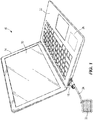
- Fig. 1 illustrates a system 10 including a portable electronic device 14 and a security apparatus 18.
- the portable electronic device 14 is a laptop computer, but may alternatively be a tablet computer, a smartphone, an eReader, an MP3 player, and the like.
- the illustrated portable electronic device 14 includes a housing 22, a processor 26 positioned within the housing 22, and a screen 30 supported by the housing 22.
- the screen 30 may be a touchscreen.
- the portable electronic device 14 may also or alternatively include other input mechanisms, such as a keyboard, keypad, or touchpad.
- the security apparatus 18 is connected to the portable electronic device 14 and includes a cable 34 to secure the portable electronic device 14 to an immovable object 38, such as a table, a chair, a bracket, a wall, and the like.
- the portable electronic device 14 has an aperture 42, or slot, formed in the housing 22.
- the illustrated aperture 42 is generally smaller than existing security slots in portable electronic devices, and is specifically designed for thinner devices with smaller housings.
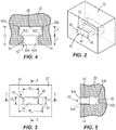
- the aperture 42 is defined by an upper wall 43, a lower wall 44, two opposing sidewalls 45, and a rear wall 46.
- the upper and lower walls 43, 44 are generally parallel to each other.
- the upper wall 43 has a first section 43A near the outer surface of the housing 22, and a second section 43B inward of the first section 43A.
- the lower wall 44 has a first section 44A near the outer surface of the housing 22, and a second section 44B inward of the first section 44A.
- the second sections 43B, 44B are slightly offset relative to the first sections 43A, 44A.
- the sidewalls 45 are generally parallel to each other and perpendicular to the upper and lower walls 43, 44.
- Each sidewall 45 has a first section 45A near the outer surface of the housing 22, and a second section 45B inward of the first section 45A.
- the second sections 45B are outwardly offset from the first sections 45A such that a shoulder or ledge 45C is formed between the first and second sections 45A, 45B.
- the rear wall 46 extends between and connects the upper wall 43, the lower wall 44, and the sidewalls 45. The rear wall 46 also closes the back of the aperture 42 to separate the aperture 42 from the internal components of the device 14.
- the aperture 42 can have an external width W 1 (measured between the first sections 44A of the sidewalls 44) of about 6 mm.
- the aperture 42 can also have an external height H 1 (measured between the upper and lower walls 43A, 43B) of about 2.5 mm.
- the aperture 42 can have an internal width W 2 (measured between the second sections 44B of the sidewalls 44) of at least 9 mm.
- the aperture 42 can have an internal depth D (measured from the outer surface of the housing 22 to the rear wall 46) of at least 7 mm.
- the internal depth D is defined by a wall thickness T (i.e., the length of the first sections 43A, 44A, 45A) and a clearance depth C (i.e., the length of the second sections 43B, 44B, 45B).
- the wall thickness T may be 3.5 mm ⁇ 0.25 mm.
- the clearance depth C may be at least 3.5 mm.
- the aperture 42 can also have an internal height H 2 (measured between the second sections 43B, 44B of the upper and lower walls 43, 44) of at least 2.65 mm. In other embodiments, the aperture 42 can have other dimensions.
- the aperture 42 is configured to receive an engagement mechanism of a security apparatus, such as one of the security apparatuses described below.
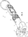
- Figs. 6-11 illustrate one example of the security apparatus 18.
- the security apparatus 18 includes a cylindrical body 48, a lock mechanism 50, and an engagement mechanism 54.
- the cylindrical body 48 is made of a relatively hard material, such as metal, and houses other components of the security apparatus 18. In other embodiments, the cylindrical body 48 can have other, non-cylindrical shapes.
- the illustrated body 48 includes a knurled section 58 to facilitate grasping and holding the security apparatus 18.
- the illustrated lock mechanism 50 includes a lock cylinder 62 and a cam member 66.
- the lock cylinder 62 and the cam member 66 are positioned within the cylindrical body 48.
- the lock cylinder 62 is arranged in line with the engagement mechanism 54 along a longitudinal axis 70 of the security apparatus 18.
- the lock cylinder 62 also defines the longitudinal axis 70 and is actuatable (e.g., rotatable) about the axis 70.
- the lock cylinder 62 is rotatable by a key 74 ( Fig. 6 ).
- the cam member 66 is coupled to the lock cylinder 62 for rotation with the lock cylinder 62 about the longitudinal axis 70.
- the cam member 66 includes a stem 78 that extends into the lock cylinder 62, and a cam body 82 positioned forward of the lock cylinder 62 and engaging the engagement mechanism 54.
- the cam member 66 has one or more slots 86 formed in the cam body 82.
- the illustrated slots 86 are arcuate slots that curve around the circumference of the cam body 82.
- the slots 86 are also obliquely angled relative to the longitudinal axis 70 so that the slots 86 helically wind around cam body 82.
- Each slot 86 includes a first end 90 adjacent the engagement mechanism 54, a second end 94 adjacent the lock cylinder 62, and a detent 98 formed at the first end 90.
- the cam member 66 may include fewer or more slots 86 formed in the cam body 82.
- the illustrated engagement mechanism 54 includes two fingers 102 and a plunger 106.
- the fingers 102 are movable (e.g., pivotable) between an unlocked or retracted position ( Fig. 7 ) and a locked or expanded position ( Fig. 8 ).
- the engagement mechanism 54 is insertable into and removable from the aperture 42 in the portable electronic device 14 ( Figs. 1-5 ).
- the engagement mechanism 54 engages the housing 22 of the portable electronic device 14 to secure the security apparatus 18 to the device 14.
- Each finger 102 includes an enlarged distal end 110 and a relatively narrower stem 114.
- the enlarged distal ends 110 facilitate engaging (e.g., contacting or "grabbing) the housing 22 of the portable electronic device 14 so that the security apparatus 18 cannot be pulled out of the aperture 42. Particularly, the enlarged distal ends 110 engage the ledges 45C of the sidewalls 45 ( Fig. 4 ) formed by the aperture 42.
- the relatively narrower stems 114 create a recessed area 118 between the fingers 102 for receiving the plunger 106.
- Each finger 102 also includes a boss 116 at an end of the stem 114 opposite from the enlarged distal end 110. The bosses 116 define spaced apart pivot axes for the fingers 102.
- the plunger 106 is positioned between the fingers 102 to selectively move the fingers 102 from the unlocked position to the locked position.
- the plunger 106 includes cam followers 122 that are received in the slots 86 of the cam member 66.
- the cam followers 122 are pins.
- the plunger 106 may include fewer or more cam followers 122, depending on the number of slots 86 in the cam member 66.
- the plunger 106 is movable (e.g., slidable) along the longitudinal axis 70 to selectively actuate the fingers 102.
- the security apparatus 18 also includes an end cap 126 coupled to the cylindrical body 48 opposite from the lock cylinder 62 to help retain the fingers 102 and the plunger 106 in connection with the lock mechanism 50 and the body 48.
- the cam followers 122 of the plunger 106 are positioned at the second ends 94 of the slots 86 in the cam member 66. In this position, a distal end section of the plunger 106 is received within the recessed area 118 formed between the fingers 102. The fingers 102 are moved (e.g., pivoted) toward each other so that the enlarged distal ends 110 contact each other.
- the engagement mechanism 54 may include a spring element, such as an elastomeric ring 130 shown in Fig. 11 , to help move the fingers 102 toward each other. In this position, the engagement mechanism 54 can be inserted into or removed from the aperture 42 of the portable electronic device 14.
- the cam followers 122 follow the slots 86 of the cam member 66 to move the plunger 106 axially outward.
- the plunger 106 slides axially outward (i.e., in the direction of arrow A)
- the plunger 106 pushes the fingers 102 apart from each other (i.e., in the direction of arrows B). More particularly, the fingers 102 are pushed and expanded radially outward to engage the housing 22 of the portable electronic device 14 (if the engagement mechanism 54 is inserted into the aperture 42 of the portable electronic device 14).
- each cam follower 122 is received in the corresponding detent 98 at the first end 90 of the slot 86 when in the locked position.
- the engagement mechanism 54 is inhibited from being removed from (e.g., pulled out of) the aperture 42 of the device 14.
- the detents 98 provide recesses that inhibit the cam followers 122 from being bumped out of the first ends 90 of the slots 86 and moved back toward the second ends 94 of the slots 86 without purposefully rotating the cam member 66 (e.g., with the key 74).
- the security apparatus 18 also includes a cable mount 134 supported by the cylindrical body 48.
- the illustrated cable mount 134 is positioned generally between the lock mechanism 50 and the engagement mechanism 54.
- the cable mount 134 includes a boss 138 extending radially from the cylindrical body 48.
- the cable mount 134 is configured to securely receive an end of the flexible cable 34, which can be wrapped around an immovable object 38 ( Fig. 1 ) to secure the security apparatus 18 (and, thereby, the portable electronic device 14) to the immovable object 38.
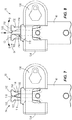
- Figs. 12-17 illustrate an example of a security apparatus 218 not embodying the invention.
- the security apparatus 218 is similar to the security apparatus 18 discussed above with reference to Figs. 6-11 . Differences between the two security apparatuses 18, 218 are described below.
- the security apparatus 218 includes a body 222, a lock mechanism 226, and an engagement mechanism 230.
- the body 222 has a first body portion 234 that generally houses the lock mechanism 226, and a second body portion 238 that generally houses the engagement mechanism 230.
- the body portions 234, 238 are arranged generally perpendicular to each other so that the first body portion 234 extends upward (e.g., away from a table or other surface supporting the portable electronic device 14) relative to the second body portion 238.
- the illustrated lock mechanism 226 includes a lock cylinder 242 and a cam member 246.
- the lock cylinder 242 is arranged at 90 degrees relative to a longitudinal axis 250 of the engagement mechanism 230 and the second body portion 238.
- the lock cylinder 242 is rotatable by, for example, a key 254 ( Fig. 12 ).
- the lock mechanism 226 may include a combination-style lock.
- the cam member 246 is coupled to the lock cylinder 242 for rotation with the lock cylinder 242.
- the cam member 246 includes a stem 258 that extends into the lock cylinder 242, and an enlarged cam 262 coupled to a distal end of the stem 258, opposite from the lock cylinder 242.
- the enlarged cam 262 engages the engagement mechanism 230 to actuate the engagement mechanism 230.
- the illustrated engagement mechanism 230 includes two fingers 266 and plunger 270.
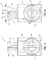
- the fingers 266 are movable (e.g., pivotable) between an unlocked or retracted position ( Fig. 13 ) and a locked or expanded position ( Fig. 14 ).
- the engagement mechanism 230 is insertable into and removable from the aperture 42 in the portable electronic device 14 ( Figs. 1-5 ).
- the engagement mechanism 230 engages the housing 22 of the portable electronic device 14 to secure the security apparatus 218 to the device 14.
- the illustrated plunger 270 is partially received in a guide block 272.
- the guide block 272 helps restrict movement of the plunger 270 to linear sliding movement in the direction of arrow C.
- the guide block 272 also forms part of a bottom section of the body 222.
- the guide block 272 is a separate piece from the rest of the body 222 to facilitate assembling the security apparatus 218.
- the fingers 266 are moved between the unlocked and locked positions by rotating the cam member 246 with the lock cylinder 242.
- the plunger 270 includes a recess 274, or cam follower, that receives the enlarged cam 262 of the cam member 246.
- the cam member 246 is rotated (e.g., by rotating the lock cylinder 242 with the key 254), the enlarged cam 262 pushes the plunger 270 axially outward or inward, depending on which direction the cam member 246 is rotated.
- the plunger 270 slides axially outward (i.e., in the direction of arrow C)
- the fingers 266 are pushed apart and expanded radially outward (i.e., in the direction of arrows D).
- the fingers 266 can move toward each other.
- the distal ends of the fingers 266 include corresponding cutouts 278 such that the fingers 266 can slightly overlap when in the unlocked position (as shown in Fig. 13 ).
- the engagement mechanism 230 may include a spring element, such as an elastomeric ring 280 shown in Fig. 17 , to help move the fingers 266 toward each other.
- the security apparatus 218 also includes a cable mount 282 supported at an end of the body 222 opposite from the engagement mechanism 230.
- the cable mount 282 is configured to securely receive an end of a flexible cable 286.
- the flexible cable 286 can be, for example, wrapped around an immovable object 38 ( Fig. 1 ) to secure the security apparatus 218 to the immovable object 38.
- the illustrated cable mount 282 also includes a joint 290 that allows the cable 286 to be pivoted relative to the body 222.
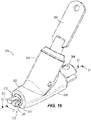
- Figs. 18-23 illustrate another example of a security apparatus 318 not embodying the invention.
- the security apparatus 318 is similar to the security apparatus 18 discussed above with reference to Figs. 6-11 . Differences between the two security apparatuses 18, 318 are described below.
- the security apparatus 318 includes a body 322, a lock mechanism 326, and an engagement mechanism 330.
- the body 322 has a first body portion 334 that generally houses the lock mechanism 326, and a second body portion 338 that generally houses the engagement mechanism 330.
- the body portions 334, 338 are obliquely angled relative to each other.
- the first body portion 334 is angled about 45 degrees relative to the second body portion 338 such that the first body portion 334 extends upwardly and rearwardly from the second body portion 338.
- the illustrated lock mechanism 326 includes a lock cylinder 342 and a cam member 346.
- the lock cylinder 342 is arranged at 45 degrees relative to a longitudinal axis 350 of the engagement mechanism 330 and the second body portion 338.
- the lock cylinder 342 is rotatable by, for example, a key 354 ( Fig. 18 ).
- the lock mechanism 326 may include a combination-style lock.
- the cam member 346 is coupled to the lock cylinder 342 for rotation with the lock cylinder 342.
- the cam member 346 includes a stem 358 that extends into the lock cylinder 342, and an enlarged cam 362 coupled to a distal end of the stem 358, opposite from the lock cylinder 342.
- the illustrated enlarged cam 362 includes a cam surface 366 facing and contacting the engagement mechanism 330.
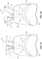
- the illustrated engagement mechanism 330 includes two fingers 370 and a cam follower 374.
- the fingers 370 are movable (e.g., pivotable) between an unlocked or retracted position ( Fig. 19 ) and a locked or expanded position ( Fig. 20 ).
- the engagement mechanism 330 is insertable into and removable from the aperture 42 in the portable electronic device 14 ( Figs. 1-5 ).
- the engagement mechanism 330 engages the housing 22 of the portable electronic device 14 to secure the security apparatus 318 to the device 14.
- the cam follower 374 is positioned between the fingers 370 and the cam member 346.
- the illustrated cam follower 374 includes two wings 378, each of which engages one of the fingers 370.
- the wings 378 have ramped surfaces 382 that selectively press proximal ends 386 of the fingers 370 together, causing distal ends 390 of the fingers 370 to spread apart.
- the fingers 370 are moved between the unlocked and locked positions by rotating the cam member 346 with the lock cylinder 342. More particularly, the cam follower 374 abuts the cam surface 366 of the cam member 346. As the cam member 346 is rotated (e.g., by rotating the lock cylinder 342 with the key 354), the enlarged cam 362 is rotated to move the cam surface 366 relative to the cam follower 374. When a recessed portion of the cam surface 366 is aligned and in contact with the cam follower 374, the cam follower 374 moves (e.g., slides) away from the fingers 370 (to the right in Fig. 21 ).
- the wings 378 of the cam follower 374 allow the proximal ends 386 of the fingers 370 to spread apart so that the distal ends 390 of the fingers 370 move toward each other.
- the cam member 346 pushes (e.g., slides) the cam follower 374 toward the fingers 370 (to the left in Fig. 21 ).
- the wings 378 of the cam follower 374 push the proximal ends 386 of the fingers 370 together so that the distal ends 390 of the fingers 370 are spread apart from each other (i.e., in the direction of arrows E).
- the security apparatus 318 also includes a cable mount 394 supported on an end of the body 322 opposite from the engagement mechanism 330. Only part of the cable mount 394 is shown in the figures, but the cable mount 394 may be constructed similar to the cable mount 282 shown in Figs. 12-17 .
- the cable mount 394 is configured to securely receive a flexible cable (not shown, but similar to the cables 34, 286 described above).
- the flexible cable can be, for example, wrapped around an immovable object 38 ( Fig. 1 ) to secure the security apparatus 318 to the immovable object 38.
- the illustrated security apparatuses 18, 218, 318 provide relatively compact lock and engagement mechanisms that facilitate interfacing with thinner portable electronic devices.
- the security apparatuses 18, 218, 318 are designed to engage relatively smaller apertures in portable electronic devices, yet still provide at least the same strength of security as conventional laptop locks.
- the security apparatuses 18, 218, 318 are physically compact so that a portable electronic device can lay flat on a surface (e.g., table or desk) without interference from the attached security apparatus 18, 218, 318.
Landscapes
- Engineering & Computer Science (AREA)
- Computer Hardware Design (AREA)
- Theoretical Computer Science (AREA)
- Physics & Mathematics (AREA)
- General Engineering & Computer Science (AREA)
- Human Computer Interaction (AREA)
- General Physics & Mathematics (AREA)
- Mathematical Physics (AREA)
- Casings For Electric Apparatus (AREA)
- Burglar Alarm Systems (AREA)
- Telephone Set Structure (AREA)
- Lock And Its Accessories (AREA)
- Fittings On The Vehicle Exterior For Carrying Loads, And Devices For Holding Or Mounting Articles (AREA)
Description
- The present invention relates to security apparatuses for portable electronic devices, such as laptop computers, tablet computers, smartphones, and other mobile devices.
-
US9187934 -
US2014/026625 discloses a lock for an electronic device having a lock hole includes a lock core, a fastener, and an adapter, wherein the lock core is operable and rotatable about a first axis; the fastener is connected to the lock core and is shifted away from the first axis. The adapter is connected to the lock core and the fastener. The rotation of the lock core about the first axis drives the adapter to drive the fastener to rotate about a second axis. When the lock core is locked, the locked lock core restricts the fastener from rotating, when the lock core is unlocked, the fastener is operable to rotate. - In one embodiment, the invention provides a security apparatus for a portable electronic device. The portable electronic device has an aperture. The security apparatus includes a lock mechanism having a lock cylinder and a cam member. The lock cylinder is configured to be rotated by a key. The cam member is coupled to the lock cylinder for rotation with the lock cylinder. The cam member has a slot. The security apparatus also includes an engagement mechanism having a first finger, a second finger, and a plunger. The first finger and the second finger are configured to be inserted into the aperture of the portable electronic device. The plunger is positioned between the first finger and the second finger and has a cam follower positioned within the slot of the cam member. As the cam member is rotated by the lock cylinder, the plunger pushes the first finger and the second finger apart from each other to engage the portable electronic device.
- In another embodiment, the invention provides a system including a portable electronic device and the security apparatus. The portable electronic device has a housing, a processor positioned within the housing, a screen supported by the housing, and an aperture formed in the housing.
- In yet another embodiment, the invention provides a security apparatus for a portable electronic device according to
claim 1, wherein the engagement mechanism is movable between a first position, in which the plunger is retracted and the first and second fingers disengage the portable electronic device, and a second position, in which the plunger is extended and the first and second fingers engage the portable electronic device. - Other aspects of the invention as defined by the appended claims will become apparent by consideration of the detailed description and accompanying drawings.
-
-
Fig. 1 illustrates a system including a portable electronic device and a security apparatus embodying the present invention. -
Fig. 2 is a perspective view of a portion of the portable electronic device, the portable electronic device having an aperture. -
Fig. 3 is a front view of the portion of the portable electronic device shown inFig. 2 . -
Fig. 4 is a cross-sectional view of the portion of the portable electronic device taken along section line 4-4 ofFig. 3 . -
Fig. 5 is a cross-sectional view of the portion of the portable electronic device taken along section line 5-5 ofFig. 3 . -
Fig. 6 is a perspective view of the security apparatus shown inFig. 1 . -
Fig. 7 is a top view of a portion of the security apparatus ofFig. 6 while in an unlocked position. -
Fig. 8 is a top view of the portion of the security apparatus ofFig. 6 while in a locked position. -
Fig. 9 is a top view of the security apparatus ofFig. 6 with a cylindrical body removed. -
Fig. 10 is a side view of the security apparatus ofFig. 6 with the cylindrical body removed. -
Fig. 11 is an exploded perspective view of the security apparatus ofFig. 6 . -
Fig. 12 is a perspective view of another security apparatus, not embodying the invention. -
Fig. 13 is a top view of a portion of the security apparatus ofFig. 12 while in an unlocked position. -
Fig. 14 is a top view of the portion of the security apparatus ofFig. 12 while in a locked position. -
Fig. 15 is a cross-sectional view of the security apparatus taken along section line 15-15 ofFig. 12 . -
Fig. 16 is a cross-sectional view of the security apparatus taken along section line 16-16 ofFig. 12 . -
Fig. 17 is an exploded perspective view of the security apparatus ofFig. 12 . -
Fig. 18 is a perspective view of yet another security apparatus, not embodying the invention. -
Fig. 19 is a top view of a portion of the security apparatus ofFig. 18 while in an unlocked position. -
Fig. 20 is a top view of the portion of the security apparatus ofFig. 18 while in a locked position. -
Fig. 21 is a cross-sectional view of the security apparatus taken along section line 21-21 ofFig. 18 . -
Fig. 22 is a cross-sectional view of the security apparatus taken along section line 22-22 ofFig. 18 . -
Fig. 23 is an exploded perspective view of the security apparatus ofFig. 18 . - Before any embodiments of the invention are explained in detail, it is to be understood that the invention is not limited in its application to the details of construction and the arrangement of components set forth in the following description or illustrated in the following drawings. The invention is capable of other embodiments and of being practiced or of being carried out in various ways, as they are defined by the appended claims.
-
Fig. 1 illustrates asystem 10 including a portableelectronic device 14 and asecurity apparatus 18. In the illustrated embodiment, the portableelectronic device 14 is a laptop computer, but may alternatively be a tablet computer, a smartphone, an eReader, an MP3 player, and the like. The illustrated portableelectronic device 14 includes ahousing 22, aprocessor 26 positioned within thehousing 22, and ascreen 30 supported by thehousing 22. In some embodiments, thescreen 30 may be a touchscreen. In other embodiments, such as the illustrated embodiment, the portableelectronic device 14 may also or alternatively include other input mechanisms, such as a keyboard, keypad, or touchpad. Thesecurity apparatus 18 is connected to the portableelectronic device 14 and includes acable 34 to secure the portableelectronic device 14 to animmovable object 38, such as a table, a chair, a bracket, a wall, and the like. - As shown in
Figs. 2-5 , the portableelectronic device 14 has anaperture 42, or slot, formed in thehousing 22. The illustratedaperture 42 is generally smaller than existing security slots in portable electronic devices, and is specifically designed for thinner devices with smaller housings. Theaperture 42 is defined by anupper wall 43, alower wall 44, twoopposing sidewalls 45, and arear wall 46. As shown inFig. 5 , the upper andlower walls upper wall 43 has afirst section 43A near the outer surface of thehousing 22, and asecond section 43B inward of thefirst section 43A. Similarly, thelower wall 44 has afirst section 44A near the outer surface of thehousing 22, and asecond section 44B inward of thefirst section 44A. Thesecond sections first sections Fig. 4 , thesidewalls 45 are generally parallel to each other and perpendicular to the upper andlower walls sidewall 45 has afirst section 45A near the outer surface of thehousing 22, and asecond section 45B inward of thefirst section 45A. Thesecond sections 45B are outwardly offset from thefirst sections 45A such that a shoulder orledge 45C is formed between the first andsecond sections rear wall 46 extends between and connects theupper wall 43, thelower wall 44, and thesidewalls 45. Therear wall 46 also closes the back of theaperture 42 to separate theaperture 42 from the internal components of thedevice 14. - By way of example, the
aperture 42 can have an external width W1 (measured between thefirst sections 44A of the sidewalls 44) of about 6 mm. Theaperture 42 can also have an external height H1 (measured between the upper andlower walls aperture 42 can have an internal width W2 (measured between thesecond sections 44B of the sidewalls 44) of at least 9 mm. Further, theaperture 42 can have an internal depth D (measured from the outer surface of thehousing 22 to the rear wall 46) of at least 7 mm. The internal depth D is defined by a wall thickness T (i.e., the length of thefirst sections second sections aperture 42 can also have an internal height H2 (measured between thesecond sections lower walls 43, 44) of at least 2.65 mm. In other embodiments, theaperture 42 can have other dimensions. Theaperture 42 is configured to receive an engagement mechanism of a security apparatus, such as one of the security apparatuses described below. -
Figs. 6-11 illustrate one example of thesecurity apparatus 18. Thesecurity apparatus 18 includes acylindrical body 48, alock mechanism 50, and anengagement mechanism 54. Thecylindrical body 48 is made of a relatively hard material, such as metal, and houses other components of thesecurity apparatus 18. In other embodiments, thecylindrical body 48 can have other, non-cylindrical shapes. The illustratedbody 48 includes aknurled section 58 to facilitate grasping and holding thesecurity apparatus 18. - As shown in
Figs. 9-11 , the illustratedlock mechanism 50 includes alock cylinder 62 and acam member 66. Thelock cylinder 62 and thecam member 66 are positioned within thecylindrical body 48. Thelock cylinder 62 is arranged in line with theengagement mechanism 54 along alongitudinal axis 70 of thesecurity apparatus 18. As such, thelock cylinder 62 also defines thelongitudinal axis 70 and is actuatable (e.g., rotatable) about theaxis 70. Thelock cylinder 62 is rotatable by a key 74 (Fig. 6 ). - The
cam member 66 is coupled to thelock cylinder 62 for rotation with thelock cylinder 62 about thelongitudinal axis 70. In particular, thecam member 66 includes astem 78 that extends into thelock cylinder 62, and acam body 82 positioned forward of thelock cylinder 62 and engaging theengagement mechanism 54. Thecam member 66 has one ormore slots 86 formed in thecam body 82. The illustratedslots 86 are arcuate slots that curve around the circumference of thecam body 82. Theslots 86 are also obliquely angled relative to thelongitudinal axis 70 so that theslots 86 helically wind aroundcam body 82. Eachslot 86 includes afirst end 90 adjacent theengagement mechanism 54, asecond end 94 adjacent thelock cylinder 62, and adetent 98 formed at thefirst end 90. In other embodiments, thecam member 66 may include fewer ormore slots 86 formed in thecam body 82. - As shown in
Figs. 7-8 and11 , the illustratedengagement mechanism 54 includes twofingers 102 and aplunger 106. Thefingers 102 are movable (e.g., pivotable) between an unlocked or retracted position (Fig. 7 ) and a locked or expanded position (Fig. 8 ). When thefingers 102 are in the unlocked position, theengagement mechanism 54 is insertable into and removable from theaperture 42 in the portable electronic device 14 (Figs. 1-5 ). When thefingers 102 are in the locked position, theengagement mechanism 54 engages thehousing 22 of the portableelectronic device 14 to secure thesecurity apparatus 18 to thedevice 14. Eachfinger 102 includes an enlargeddistal end 110 and a relativelynarrower stem 114. The enlarged distal ends 110 facilitate engaging (e.g., contacting or "grabbing) thehousing 22 of the portableelectronic device 14 so that thesecurity apparatus 18 cannot be pulled out of theaperture 42. Particularly, the enlarged distal ends 110 engage theledges 45C of the sidewalls 45 (Fig. 4 ) formed by theaperture 42. The relatively narrower stems 114 create a recessedarea 118 between thefingers 102 for receiving theplunger 106. Eachfinger 102 also includes aboss 116 at an end of thestem 114 opposite from the enlargeddistal end 110. Thebosses 116 define spaced apart pivot axes for thefingers 102. - The
plunger 106 is positioned between thefingers 102 to selectively move thefingers 102 from the unlocked position to the locked position. Theplunger 106 includescam followers 122 that are received in theslots 86 of thecam member 66. In the illustrated embodiment, thecam followers 122 are pins. In other embodiments, theplunger 106 may include fewer ormore cam followers 122, depending on the number ofslots 86 in thecam member 66. Theplunger 106 is movable (e.g., slidable) along thelongitudinal axis 70 to selectively actuate thefingers 102. Thesecurity apparatus 18 also includes anend cap 126 coupled to thecylindrical body 48 opposite from thelock cylinder 62 to help retain thefingers 102 and theplunger 106 in connection with thelock mechanism 50 and thebody 48. - Referring to
Fig. 7 , in an initial position (i.e., when thefingers 102 are in the unlocked position), thecam followers 122 of theplunger 106 are positioned at the second ends 94 of theslots 86 in thecam member 66. In this position, a distal end section of theplunger 106 is received within the recessedarea 118 formed between thefingers 102. Thefingers 102 are moved (e.g., pivoted) toward each other so that the enlarged distal ends 110 contact each other. In some embodiments, theengagement mechanism 54 may include a spring element, such as anelastomeric ring 130 shown inFig. 11 , to help move thefingers 102 toward each other. In this position, theengagement mechanism 54 can be inserted into or removed from theaperture 42 of the portableelectronic device 14. - Referring to
Figs. 8-10 , when thecam member 66 is rotated (e.g., by rotating thelock cylinder 62 with the key 74), thecam followers 122 follow theslots 86 of thecam member 66 to move theplunger 106 axially outward. As theplunger 106 slides axially outward (i.e., in the direction of arrow A), theplunger 106 pushes thefingers 102 apart from each other (i.e., in the direction of arrows B). More particularly, thefingers 102 are pushed and expanded radially outward to engage thehousing 22 of the portable electronic device 14 (if theengagement mechanism 54 is inserted into theaperture 42 of the portable electronic device 14). Thecam member 66 is rotated about 90 degrees until thecam followers 122 reach the first ends 90 of theslots 86. As shown inFig. 10 , eachcam follower 122 is received in thecorresponding detent 98 at thefirst end 90 of theslot 86 when in the locked position. In this position, theengagement mechanism 54 is inhibited from being removed from (e.g., pulled out of) theaperture 42 of thedevice 14. In addition, thedetents 98 provide recesses that inhibit thecam followers 122 from being bumped out of the first ends 90 of theslots 86 and moved back toward the second ends 94 of theslots 86 without purposefully rotating the cam member 66 (e.g., with the key 74). - As shown in
Figs. 6 and11 , thesecurity apparatus 18 also includes acable mount 134 supported by thecylindrical body 48. The illustratedcable mount 134 is positioned generally between thelock mechanism 50 and theengagement mechanism 54. Thecable mount 134 includes aboss 138 extending radially from thecylindrical body 48. Thecable mount 134 is configured to securely receive an end of theflexible cable 34, which can be wrapped around an immovable object 38 (Fig. 1 ) to secure the security apparatus 18 (and, thereby, the portable electronic device 14) to theimmovable object 38. -
Figs. 12-17 illustrate an example of asecurity apparatus 218 not embodying the invention. Thesecurity apparatus 218 is similar to thesecurity apparatus 18 discussed above with reference toFigs. 6-11 . Differences between the twosecurity apparatuses - The
security apparatus 218 includes abody 222, alock mechanism 226, and anengagement mechanism 230. Thebody 222 has afirst body portion 234 that generally houses thelock mechanism 226, and asecond body portion 238 that generally houses theengagement mechanism 230. In the illustrated example, thebody portions first body portion 234 extends upward (e.g., away from a table or other surface supporting the portable electronic device 14) relative to thesecond body portion 238. - As shown in
Figs. 15-17 , the illustratedlock mechanism 226 includes alock cylinder 242 and acam member 246. Thelock cylinder 242 is arranged at 90 degrees relative to alongitudinal axis 250 of theengagement mechanism 230 and thesecond body portion 238. Thelock cylinder 242 is rotatable by, for example, a key 254 (Fig. 12 ). In other examples, thelock mechanism 226 may include a combination-style lock. - The
cam member 246 is coupled to thelock cylinder 242 for rotation with thelock cylinder 242. In particular, thecam member 246 includes astem 258 that extends into thelock cylinder 242, and anenlarged cam 262 coupled to a distal end of thestem 258, opposite from thelock cylinder 242. Theenlarged cam 262 engages theengagement mechanism 230 to actuate theengagement mechanism 230. - With continued reference to
Figs. 13-17 , the illustratedengagement mechanism 230 includes twofingers 266 andplunger 270. Thefingers 266 are movable (e.g., pivotable) between an unlocked or retracted position (Fig. 13 ) and a locked or expanded position (Fig. 14 ). When thefingers 266 are in the unlocked position, theengagement mechanism 230 is insertable into and removable from theaperture 42 in the portable electronic device 14 (Figs. 1-5 ). When thefingers 266 are in the locked position, theengagement mechanism 230 engages thehousing 22 of the portableelectronic device 14 to secure thesecurity apparatus 218 to thedevice 14. - The illustrated
plunger 270 is partially received in aguide block 272. Theguide block 272 helps restrict movement of theplunger 270 to linear sliding movement in the direction of arrow C. Theguide block 272 also forms part of a bottom section of thebody 222. In the illustrated embodiment, theguide block 272 is a separate piece from the rest of thebody 222 to facilitate assembling thesecurity apparatus 218. - In the illustrated example, the
fingers 266 are moved between the unlocked and locked positions by rotating thecam member 246 with thelock cylinder 242. More particularly, theplunger 270 includes arecess 274, or cam follower, that receives theenlarged cam 262 of thecam member 246. When thecam member 246 is rotated (e.g., by rotating thelock cylinder 242 with the key 254), theenlarged cam 262 pushes theplunger 270 axially outward or inward, depending on which direction thecam member 246 is rotated. As theplunger 270 slides axially outward (i.e., in the direction of arrow C), thefingers 266 are pushed apart and expanded radially outward (i.e., in the direction of arrows D). As theplunger 270 slides axially inward, thefingers 266 can move toward each other. In the illustrated example, the distal ends of thefingers 266 include correspondingcutouts 278 such that thefingers 266 can slightly overlap when in the unlocked position (as shown inFig. 13 ). In some examples, theengagement mechanism 230 may include a spring element, such as anelastomeric ring 280 shown inFig. 17 , to help move thefingers 266 toward each other. - As shown in
Figs. 12 and17 , thesecurity apparatus 218 also includes acable mount 282 supported at an end of thebody 222 opposite from theengagement mechanism 230. Thecable mount 282 is configured to securely receive an end of aflexible cable 286. Theflexible cable 286 can be, for example, wrapped around an immovable object 38 (Fig. 1 ) to secure thesecurity apparatus 218 to theimmovable object 38. The illustratedcable mount 282 also includes a joint 290 that allows thecable 286 to be pivoted relative to thebody 222. -
Figs. 18-23 illustrate another example of asecurity apparatus 318 not embodying the invention. Thesecurity apparatus 318 is similar to thesecurity apparatus 18 discussed above with reference toFigs. 6-11 . Differences between the twosecurity apparatuses - The
security apparatus 318 includes abody 322, alock mechanism 326, and anengagement mechanism 330. Thebody 322 has afirst body portion 334 that generally houses thelock mechanism 326, and asecond body portion 338 that generally houses theengagement mechanism 330. Thebody portions first body portion 334 is angled about 45 degrees relative to thesecond body portion 338 such that thefirst body portion 334 extends upwardly and rearwardly from thesecond body portion 338. - As shown in
Figs. 21-22 , the illustratedlock mechanism 326 includes alock cylinder 342 and acam member 346. Thelock cylinder 342 is arranged at 45 degrees relative to alongitudinal axis 350 of theengagement mechanism 330 and thesecond body portion 338. Thelock cylinder 342 is rotatable by, for example, a key 354 (Fig. 18 ). In other examples, thelock mechanism 326 may include a combination-style lock. - The
cam member 346 is coupled to thelock cylinder 342 for rotation with thelock cylinder 342. In particular, thecam member 346 includes astem 358 that extends into thelock cylinder 342, and anenlarged cam 362 coupled to a distal end of thestem 358, opposite from thelock cylinder 342. The illustratedenlarged cam 362 includes acam surface 366 facing and contacting theengagement mechanism 330. - The illustrated
engagement mechanism 330 includes twofingers 370 and acam follower 374. Thefingers 370 are movable (e.g., pivotable) between an unlocked or retracted position (Fig. 19 ) and a locked or expanded position (Fig. 20 ). When thefingers 370 are in the unlocked position, theengagement mechanism 330 is insertable into and removable from theaperture 42 in the portable electronic device 14 (Figs. 1-5 ). When thefingers 370 are in the locked position, theengagement mechanism 330 engages thehousing 22 of the portableelectronic device 14 to secure thesecurity apparatus 318 to thedevice 14. - The
cam follower 374 is positioned between thefingers 370 and thecam member 346. The illustratedcam follower 374 includes twowings 378, each of which engages one of thefingers 370. Thewings 378 have rampedsurfaces 382 that selectively press proximal ends 386 of thefingers 370 together, causing distal ends 390 of thefingers 370 to spread apart. - In the illustrated example, the
fingers 370 are moved between the unlocked and locked positions by rotating thecam member 346 with thelock cylinder 342. More particularly, thecam follower 374 abuts thecam surface 366 of thecam member 346. As thecam member 346 is rotated (e.g., by rotating thelock cylinder 342 with the key 354), theenlarged cam 362 is rotated to move thecam surface 366 relative to thecam follower 374. When a recessed portion of thecam surface 366 is aligned and in contact with thecam follower 374, thecam follower 374 moves (e.g., slides) away from the fingers 370 (to the right inFig. 21 ). As thecam follower 374 moves away from thefingers 370, thewings 378 of thecam follower 374 allow the proximal ends 386 of thefingers 370 to spread apart so that the distal ends 390 of thefingers 370 move toward each other. When a protruding portion of thecam surface 366 is aligned and in contact with thecam follower 374, thecam member 346 pushes (e.g., slides) thecam follower 374 toward the fingers 370 (to the left inFig. 21 ). As thecam follower 374 moves toward thefingers 370, thewings 378 of thecam follower 374 push the proximal ends 386 of thefingers 370 together so that the distal ends 390 of thefingers 370 are spread apart from each other (i.e., in the direction of arrows E). - As shown in
Figs. 18 and23 , thesecurity apparatus 318 also includes acable mount 394 supported on an end of thebody 322 opposite from theengagement mechanism 330. Only part of thecable mount 394 is shown in the figures, but thecable mount 394 may be constructed similar to thecable mount 282 shown inFigs. 12-17 . Thecable mount 394 is configured to securely receive a flexible cable (not shown, but similar to thecables Fig. 1 ) to secure thesecurity apparatus 318 to theimmovable object 38. - The illustrated
security apparatuses security apparatuses security apparatuses security apparatus - Various features and advantages of the invention are set forth in the following claims.
Claims (15)
- A security apparatus (18) for a portable electronic device (14), the portable electronic device (14) having an aperture (42), the security apparatus (18) comprising:a lock mechanism (50) including a lock cylinder (62) and a cam member (66), the lock cylinder (62) configured to be rotated by a key (74), the cam member (66) coupled to the lock cylinder (62) for rotation with the lock cylinder (62), the cam member (66) having a slot (86); andan engagement mechanism including a first finger (102), a second finger (102), and a plunger (106), the first finger (102) and the second finger (102) configured to be inserted into the aperture (42) of the portable electronic device (14), the plunger (106) positioned between the first finger (102) and the second finger (102) and having a cam follower (122) positioned within the slot (86) of the cam member (66),wherein as the cam member (66) is rotated by the lock cylinder (62), the plunger (106) pushes the first finger (102) and the second finger (102) apart from each other to engage the portable electronic device (14), wherein:the lock cylinder (62) defines a longitudinal axis (70), and wherein the cam member (66) is rotatable about the longitudinal axis (70);the plunger (106) moves along the longitudinal axis (70) as the cam member (66) is rotated by the lock cylinder (62); andthe slot (86) of the cam member (66) is obliquely angled relative to the longitudinal axis (70).
- The security apparatus (18) of claim 1, wherein the first finger (102) and the second finger (102) pivot apart from each other.
- The security apparatus (18) of claim 1, wherein the plunger (106) moves from a retracted position relative to the first and second fingers (102) to an extended position relative to the first and second fingers (102) as the cam member (66) is rotated.
- The security apparatus (18) of any preceding claim, wherein the slot (86) includes a first end (90), a second end (94), and a detent (98) formed at the first end (90), and wherein the cam follower (122) is received in the detent (98) when the plunger (106) pushes the first finger (102) and the second finger (102) apart from each other.
- The security apparatus (18) of any preceding claim, wherein the slot (86) is a first slot and the cam follower (122) is a first cam follower, wherein the cam member (66) has a second slot (86) spaced apart from the first slot (86), and wherein the plunger (106) includes a second cam follower (122) positioned within the second slot (86) of the cam member (66).
- The security apparatus (18) of any preceding claim, further comprising:a cylindrical body (48), wherein the lock cylinder (62) and the cam member (66) are positioned within the cylindrical body (48); anda cable (34) secured to the cylindrical body (48), wherein the cable (34) is configured to engage an immovable object (38).
- The security apparatus (18) of claim 6, further comprising a cable mount (134) supported by the cylindrical body (48) and positioned between the lock mechanism (50) and the engagement mechanism, wherein the cable mount (134) includes a boss (116) extending radially from the cylindrical body (48), and wherein an end of the cable (34) is secured to the boss (116).
- A security apparatus (18) for any preceding claim, wherein rotation of the cam member (66) moves the plunger (106) relative to the first and second fingers (102), the engagement mechanism being movable between a first position, in which the plunger (106) is retracted and the first and second fingers (102) disengage the portable electronic device (14), and a second position, in which the plunger (106) is extended and the first and second fingers (102) engage the portable electronic device (14).
- The security apparatus (18) of claim 8, wherein the first and second fingers (102) move apart from each other when the engagement mechanism moves from the first position to the second position.
- The security apparatus (18) of claim 9, wherein the first and second fingers (102) pivot apart from each other when the engagement mechanism moves from the first position to the second position.
- The security apparatus (18) of claim 1, wherein the plunger (106) moves along the longitudinal axis (70) when the engagement mechanism moves between the first and second positions.
- The security apparatus (18) of claims 8 to 11, wherein the slot (86) includes a first end (90), a second end (94), and a detent (98) formed at the first end (90), and wherein the cam follower (122) is received in the detent (98) when the engagement mechanism is in the second position.
- The security apparatus (18) of claims 8 to 12, further comprising:a cylindrical body (48), wherein the lock cylinder (62) and the cam member (66) are positioned within the cylindrical body (48); anda cable (34) secured to the cylindrical body (48), wherein the cable (34) is configured to engage an immovable object (38).
- The security apparatus (18) of claim 13, further comprising a cable mount (134) supported by the cylindrical body (48) and positioned between the lock mechanism (50) and the engagement mechanism, wherein the cable mount (134) includes a boss (116) extending radially from the cylindrical body (48), and wherein an end of the cable (34) is secured to the boss (116).
- A system (10) comprising:a portable electronic device (14) having a housing (22), a processor (26) positioned within the housing (22), a screen (30) supported by the housing (22), and an aperture (42) formed in the housing (22); andthe security apparatus (18) of claim 1.
Applications Claiming Priority (2)
| Application Number | Priority Date | Filing Date | Title |
|---|---|---|---|
| US201662299848P | 2016-02-25 | 2016-02-25 | |
| PCT/US2017/018698 WO2017147065A1 (en) | 2016-02-25 | 2017-02-21 | Security apparatus for portable electronic device |
Publications (3)
| Publication Number | Publication Date |
|---|---|
| EP3397828A1 EP3397828A1 (en) | 2018-11-07 |
| EP3397828A4 EP3397828A4 (en) | 2019-01-23 |
| EP3397828B1 true EP3397828B1 (en) | 2020-04-08 |
Family
ID=59679434
Family Applications (1)
| Application Number | Title | Priority Date | Filing Date |
|---|---|---|---|
| EP17757063.7A Active EP3397828B1 (en) | 2016-02-25 | 2017-02-21 | Security apparatus for portable electronic device |
Country Status (7)
| Country | Link |
|---|---|
| US (5) | US10400482B2 (en) |
| EP (1) | EP3397828B1 (en) |
| JP (2) | JP6840766B2 (en) |
| CN (2) | CN112096196A (en) |
| AU (1) | AU2017223387A1 (en) |
| TW (5) | TWI840275B (en) |
| WO (1) | WO2017147065A1 (en) |
Families Citing this family (28)
| Publication number | Priority date | Publication date | Assignee | Title |
|---|---|---|---|---|
| AU2017223387A1 (en) | 2016-02-25 | 2018-08-23 | ACCO Brands Corporation | Security apparatus for portable electronic device |
| US11236529B2 (en) * | 2016-08-05 | 2022-02-01 | ACCO Brands Corporation | Security apparatus for a portable electronic device |
| JP2020510921A (en) | 2017-03-01 | 2020-04-09 | アッコ ブランズ コーポレイションACCO Brands Corporation | Dock for portable electronic devices |
| US10355805B2 (en) | 2017-08-10 | 2019-07-16 | Luxtera, Inc. | Method and system for a free space CWDM MUX/DEMUX for integration with a grating coupler based silicon photonics platform |
| CN108222708B (en) * | 2018-02-06 | 2023-08-15 | 厦门美科安防科技股份有限公司 | Square computer lock |
| US10917986B2 (en) * | 2018-03-08 | 2021-02-09 | ACCO Brands Corporation | Dock for a portable electronic device |
| USD892123S1 (en) | 2018-07-16 | 2020-08-04 | ACCO Brands Corporation | Dock for a portable electronic device |
| US11203886B2 (en) * | 2018-09-10 | 2021-12-21 | Sinox Co., Ltd | Security lock for electronic device |
| US10808431B2 (en) * | 2018-12-10 | 2020-10-20 | Jason Su | Lock for electronic devices |
| US11203885B2 (en) * | 2018-12-10 | 2021-12-21 | Jason Su | Combination lock for electronic devices |
| JP7070936B2 (en) * | 2020-02-05 | 2022-05-18 | 株式会社ルーペックスジャパン | Equipment anti-theft fittings |
| EP4209646B1 (en) * | 2020-11-23 | 2024-07-03 | ACCO Brands Corporation | Security apparatus having a removable lock tip |
| US12077992B2 (en) * | 2020-12-01 | 2024-09-03 | ACCO Brands Corporation | Security anchor for portable electronic device |
| US11808061B2 (en) * | 2020-12-28 | 2023-11-07 | Jin Tay Industries Co., Ltd. | Anti-theft lock for portable electronic device |
| CN114776140B (en) * | 2021-01-22 | 2023-11-28 | 金泰祥精密五金(昆山)有限公司 | Locks |
| TWI778805B (en) * | 2021-09-23 | 2022-09-21 | 金泰工業有限公司 | Universal portable electronic device anti-theft lock |
| US12012784B2 (en) * | 2021-11-04 | 2024-06-18 | Jin Tay Industries Co., Ltd. | Universal security lock for portable electronic devices and engaging mechanism thereof |
| US12012783B2 (en) * | 2021-11-04 | 2024-06-18 | Jin Tay Industries Co., Ltd. | Universal security lock for portable electronic devices |
| US12044041B2 (en) * | 2021-11-04 | 2024-07-23 | Jin Tay Industries Co., Ltd. | Universal security lock for portable electronic devices |
| CN114016824B (en) * | 2021-11-11 | 2025-10-03 | 利泰物联网科技(广东)有限公司 | Universal anti-theft lock for portable electronic devices |
| US20230203849A1 (en) * | 2021-12-29 | 2023-06-29 | Meir Avganim | Computer security locks and system therefor |
| TWM636700U (en) * | 2022-06-09 | 2023-01-21 | 競泰股份有限公司 | lock |
| TWI819790B (en) * | 2022-09-13 | 2023-10-21 | 競泰股份有限公司 | security device lock |
| US20240218709A1 (en) * | 2022-12-30 | 2024-07-04 | Meir Avganim | Slot locks and security slots therefor |
| US20250075535A1 (en) * | 2023-09-05 | 2025-03-06 | ACCO Brands Corporation | Security apparatus having a removable plunger |
| CN119597112B (en) * | 2023-09-08 | 2025-12-12 | 英业达科技有限公司 | Notebook computer and assembly rack |
| TWI862165B (en) * | 2023-09-13 | 2024-11-11 | 英業達股份有限公司 | Notebook computer and mount frame |
| EP4650556A3 (en) * | 2024-04-22 | 2026-01-14 | ACCO Brands Corporation | Data port security lock |
Family Cites Families (38)
| Publication number | Priority date | Publication date | Assignee | Title |
|---|---|---|---|---|
| US1907625A (en) * | 1930-03-24 | 1933-05-09 | Knape & Vogt Mfg Co | Showcase sliding doorlock |
| JP3607295B2 (en) * | 1994-11-15 | 2005-01-05 | ケンシントン マイクロウェア リミティド | Computer physical safety device |
| JPH1113327A (en) * | 1997-06-23 | 1999-01-19 | Sugatsune Ind Co Ltd | Burglarproof lucking tool |
| US5913907A (en) * | 1998-04-30 | 1999-06-22 | Lee; Miko | Lock for securing a portable computer or the like |
| GB2357314A (en) * | 1999-12-15 | 2001-06-20 | Arg Security Ltd | Security device e.g.for preventing theft of laptop computers |
| US6672117B2 (en) * | 2001-12-31 | 2004-01-06 | Chun Te Yu | Shielded window structure of numeral lock |
| TW534156U (en) * | 2001-12-31 | 2003-05-21 | Jiun-De You | Improved latch structure for cable locks |
| TW534155U (en) * | 2001-12-31 | 2003-05-21 | Jiun-De You | Improved structure of cable locks |
| CN100408799C (en) * | 2002-07-24 | 2008-08-06 | 艾可品牌美国有限公司 | Lock for locking display objects and method of use thereof |
| CA2533511C (en) * | 2003-07-23 | 2012-01-10 | Acco Brands, Inc. | Computer physical security device with retractable cable |
| US6968716B1 (en) * | 2004-08-31 | 2005-11-29 | Sinox Co., Ltd. | Connection lock executing locking operation without keys |
| US20060112740A1 (en) * | 2004-11-29 | 2006-06-01 | Acco Brands, Inc. | Security device including engagement member |
| TW200728580A (en) * | 2006-01-20 | 2007-08-01 | Miz Engineering Ltd | Lock apparatus for laptop computer |
| JP4791893B2 (en) * | 2006-06-13 | 2011-10-12 | 有限会社ケイ・ワイ・ティ | Security lock |
| US7331203B2 (en) * | 2006-06-23 | 2008-02-19 | Miko Lee | Merchandise lock |
| TWI288198B (en) * | 2006-08-14 | 2007-10-11 | Miz Engineering Ltd | Lock device of computer |
| CN101131059B (en) * | 2006-08-25 | 2011-05-25 | 日春国际有限公司 | Computer lock device |
| US20110013361A1 (en) * | 2006-10-23 | 2011-01-20 | Acco Brands Usa Llc | Security apparatus |
| US8746020B2 (en) | 2007-01-05 | 2014-06-10 | Scott R. Anderson | Portable equipment security device |
| US7614266B2 (en) * | 2007-10-15 | 2009-11-10 | Acco Brands Usa Llc | Security apparatus with reset mechanism |
| TW200934948A (en) * | 2008-02-15 | 2009-08-16 | Sinox Co Ltd | Burglarproof lock and burglarproof system using the same |
| JP2010229724A (en) * | 2009-03-27 | 2010-10-14 | Roasu Kk | Antitheft locking implement |
| JP2010229725A (en) * | 2009-03-27 | 2010-10-14 | Roasu Kk | Antitheft locking implement |
| JP2011002935A (en) | 2009-06-17 | 2011-01-06 | Toshiba Corp | Electronic apparatus |
| US8695384B2 (en) * | 2010-07-06 | 2014-04-15 | Sinox Company Ltd. | Lock structure |
| US8485005B2 (en) * | 2011-02-25 | 2013-07-16 | Handyway Co., Ltd. | Computer lock |
| DE202011000521U1 (en) * | 2011-03-09 | 2011-06-09 | Handyway Co., Ltd. | computer Castle |
| TWM427758U (en) | 2011-08-05 | 2012-04-21 | Sinox Co Ltd | Burglarproof lock for electrical device |
| CN202509904U (en) * | 2012-03-14 | 2012-10-31 | 宏碁股份有限公司 | Snap mechanism |
| CN202509902U (en) | 2012-03-30 | 2012-10-31 | 胡幸明 | Antitheft padlock |
| TWM445619U (en) * | 2012-06-22 | 2013-01-21 | Sinox Co Ltd | Lock |
| TWM447911U (en) | 2012-07-24 | 2013-03-01 | Sinox Co Ltd | Lock for electronic device |
| US8991225B2 (en) * | 2012-08-20 | 2015-03-31 | Sinox Co., Ltd. | Burglarproof device for electronic device |
| US9062476B2 (en) * | 2013-08-28 | 2015-06-23 | ACCO Brands Corporation | Security apparatus including a remote actuator assembly |
| TWM508581U (en) * | 2015-05-08 | 2015-09-11 | Sinox Co Ltd | Lock |
| US9187934B1 (en) * | 2015-06-10 | 2015-11-17 | Aba Ufo International Corp. | Securing device for a portable device |
| AU2017223387A1 (en) * | 2016-02-25 | 2018-08-23 | ACCO Brands Corporation | Security apparatus for portable electronic device |
| TWM553352U (en) * | 2017-06-16 | 2017-12-21 | 競泰股份有限公司 | Attachment element and lock with the same |
-
2017
- 2017-02-21 AU AU2017223387A patent/AU2017223387A1/en not_active Abandoned
- 2017-02-21 EP EP17757063.7A patent/EP3397828B1/en active Active
- 2017-02-21 JP JP2018543249A patent/JP6840766B2/en active Active
- 2017-02-21 CN CN202011000561.3A patent/CN112096196A/en active Pending
- 2017-02-21 US US15/438,102 patent/US10400482B2/en active Active
- 2017-02-21 CN CN201780013222.9A patent/CN108699866B/en active Active
- 2017-02-21 WO PCT/US2017/018698 patent/WO2017147065A1/en not_active Ceased
- 2017-02-24 TW TW112126899A patent/TWI840275B/en active
- 2017-02-24 TW TW106106502A patent/TWI750153B/en active
- 2017-02-24 TW TW111119796A patent/TWI810954B/en not_active IP Right Cessation
- 2017-02-24 TW TW110144343A patent/TWI769958B/en active
- 2017-02-24 TW TW112146559A patent/TWI843683B/en active
-
2019
- 2019-07-17 US US16/513,983 patent/US11187014B2/en active Active
-
2021
- 2021-02-17 JP JP2021022965A patent/JP7072094B2/en active Active
- 2021-06-11 US US17/345,196 patent/US11686129B2/en active Active
-
2022
- 2022-10-10 US US17/962,725 patent/US11680429B2/en active Active
-
2023
- 2023-05-03 US US18/142,932 patent/US12116808B2/en active Active
Non-Patent Citations (1)
| Title |
|---|
| None * |
Also Published As
| Publication number | Publication date |
|---|---|
| TW202411518A (en) | 2024-03-16 |
| US11187014B2 (en) | 2021-11-30 |
| US20170247916A1 (en) | 2017-08-31 |
| CN108699866B (en) | 2020-10-23 |
| US20240003168A1 (en) | 2024-01-04 |
| US11686129B2 (en) | 2023-06-27 |
| JP2021102911A (en) | 2021-07-15 |
| TWI840275B (en) | 2024-04-21 |
| WO2017147065A1 (en) | 2017-08-31 |
| TW202342862A (en) | 2023-11-01 |
| JP7072094B2 (en) | 2022-05-19 |
| TW201740004A (en) | 2017-11-16 |
| EP3397828A4 (en) | 2019-01-23 |
| TWI810954B (en) | 2023-08-01 |
| TW202240058A (en) | 2022-10-16 |
| AU2017223387A1 (en) | 2018-08-23 |
| EP3397828A1 (en) | 2018-11-07 |
| US20210301559A1 (en) | 2021-09-30 |
| JP6840766B2 (en) | 2021-03-10 |
| TWI769958B (en) | 2022-07-01 |
| CN108699866A (en) | 2018-10-23 |
| US20230032573A1 (en) | 2023-02-02 |
| US11680429B2 (en) | 2023-06-20 |
| CN112096196A (en) | 2020-12-18 |
| TWI843683B (en) | 2024-05-21 |
| US12116808B2 (en) | 2024-10-15 |
| TW202212688A (en) | 2022-04-01 |
| US10400482B2 (en) | 2019-09-03 |
| JP2019509410A (en) | 2019-04-04 |
| CA3014661A1 (en) | 2017-08-31 |
| TWI750153B (en) | 2021-12-21 |
| US20190338565A1 (en) | 2019-11-07 |
Similar Documents
| Publication | Publication Date | Title |
|---|---|---|
| EP3397828B1 (en) | Security apparatus for portable electronic device | |
| US20230160236A1 (en) | Security apparatus for portable electronic device | |
| US20210040780A1 (en) | Security apparatus including a remote actuator assembly | |
| EP4209646B1 (en) | Security apparatus having a removable lock tip | |
| US8508936B2 (en) | Portable electronic device | |
| CA3014661C (en) | Security apparatus for portable electronic device | |
| US20260009265A1 (en) | Data port security lock | |
| US20250075535A1 (en) | Security apparatus having a removable plunger |
Legal Events
| Date | Code | Title | Description |
|---|---|---|---|
| STAA | Information on the status of an ep patent application or granted ep patent |
Free format text: STATUS: THE INTERNATIONAL PUBLICATION HAS BEEN MADE |
|
| PUAI | Public reference made under article 153(3) epc to a published international application that has entered the european phase |
Free format text: ORIGINAL CODE: 0009012 |
|
| STAA | Information on the status of an ep patent application or granted ep patent |
Free format text: STATUS: REQUEST FOR EXAMINATION WAS MADE |
|
| 17P | Request for examination filed |
Effective date: 20180802 |
|
| AK | Designated contracting states |
Kind code of ref document: A1 Designated state(s): AL AT BE BG CH CY CZ DE DK EE ES FI FR GB GR HR HU IE IS IT LI LT LU LV MC MK MT NL NO PL PT RO RS SE SI SK SM TR |
|
| AX | Request for extension of the european patent |
Extension state: BA ME |
|
| A4 | Supplementary search report drawn up and despatched |
Effective date: 20190103 |
|
| RIC1 | Information provided on ipc code assigned before grant |
Ipc: E05B 73/00 20060101AFI20181219BHEP Ipc: E05B 67/08 20060101ALI20181219BHEP |
|
| DAV | Request for validation of the european patent (deleted) | ||
| DAX | Request for extension of the european patent (deleted) | ||
| GRAP | Despatch of communication of intention to grant a patent |
Free format text: ORIGINAL CODE: EPIDOSNIGR1 |
|
| STAA | Information on the status of an ep patent application or granted ep patent |
Free format text: STATUS: GRANT OF PATENT IS INTENDED |
|
| INTG | Intention to grant announced |
Effective date: 20191118 |
|
| GRAS | Grant fee paid |
Free format text: ORIGINAL CODE: EPIDOSNIGR3 |
|
| GRAA | (expected) grant |
Free format text: ORIGINAL CODE: 0009210 |
|
| STAA | Information on the status of an ep patent application or granted ep patent |
Free format text: STATUS: THE PATENT HAS BEEN GRANTED |
|
| AK | Designated contracting states |
Kind code of ref document: B1 Designated state(s): AL AT BE BG CH CY CZ DE DK EE ES FI FR GB GR HR HU IE IS IT LI LT LU LV MC MK MT NL NO PL PT RO RS SE SI SK SM TR |
|
| REG | Reference to a national code |
Ref country code: AT Ref legal event code: REF Ref document number: 1254594 Country of ref document: AT Kind code of ref document: T Effective date: 20200415 Ref country code: CH Ref legal event code: EP |
|
| REG | Reference to a national code |
Ref country code: DE Ref legal event code: R096 Ref document number: 602017014533 Country of ref document: DE |
|
| REG | Reference to a national code |
Ref country code: NL Ref legal event code: FP Ref country code: IE Ref legal event code: FG4D |
|
| REG | Reference to a national code |
Ref country code: LT Ref legal event code: MG4D |
|
| PG25 | Lapsed in a contracting state [announced via postgrant information from national office to epo] |
Ref country code: FI Free format text: LAPSE BECAUSE OF FAILURE TO SUBMIT A TRANSLATION OF THE DESCRIPTION OR TO PAY THE FEE WITHIN THE PRESCRIBED TIME-LIMIT Effective date: 20200408 Ref country code: LT Free format text: LAPSE BECAUSE OF FAILURE TO SUBMIT A TRANSLATION OF THE DESCRIPTION OR TO PAY THE FEE WITHIN THE PRESCRIBED TIME-LIMIT Effective date: 20200408 Ref country code: NO Free format text: LAPSE BECAUSE OF FAILURE TO SUBMIT A TRANSLATION OF THE DESCRIPTION OR TO PAY THE FEE WITHIN THE PRESCRIBED TIME-LIMIT Effective date: 20200708 Ref country code: PT Free format text: LAPSE BECAUSE OF FAILURE TO SUBMIT A TRANSLATION OF THE DESCRIPTION OR TO PAY THE FEE WITHIN THE PRESCRIBED TIME-LIMIT Effective date: 20200817 Ref country code: GR Free format text: LAPSE BECAUSE OF FAILURE TO SUBMIT A TRANSLATION OF THE DESCRIPTION OR TO PAY THE FEE WITHIN THE PRESCRIBED TIME-LIMIT Effective date: 20200709 Ref country code: IS Free format text: LAPSE BECAUSE OF FAILURE TO SUBMIT A TRANSLATION OF THE DESCRIPTION OR TO PAY THE FEE WITHIN THE PRESCRIBED TIME-LIMIT Effective date: 20200808 Ref country code: SE Free format text: LAPSE BECAUSE OF FAILURE TO SUBMIT A TRANSLATION OF THE DESCRIPTION OR TO PAY THE FEE WITHIN THE PRESCRIBED TIME-LIMIT Effective date: 20200408 |
|
| REG | Reference to a national code |
Ref country code: AT Ref legal event code: MK05 Ref document number: 1254594 Country of ref document: AT Kind code of ref document: T Effective date: 20200408 |
|
| PG25 | Lapsed in a contracting state [announced via postgrant information from national office to epo] |
Ref country code: BG Free format text: LAPSE BECAUSE OF FAILURE TO SUBMIT A TRANSLATION OF THE DESCRIPTION OR TO PAY THE FEE WITHIN THE PRESCRIBED TIME-LIMIT Effective date: 20200708 Ref country code: RS Free format text: LAPSE BECAUSE OF FAILURE TO SUBMIT A TRANSLATION OF THE DESCRIPTION OR TO PAY THE FEE WITHIN THE PRESCRIBED TIME-LIMIT Effective date: 20200408 Ref country code: HR Free format text: LAPSE BECAUSE OF FAILURE TO SUBMIT A TRANSLATION OF THE DESCRIPTION OR TO PAY THE FEE WITHIN THE PRESCRIBED TIME-LIMIT Effective date: 20200408 Ref country code: LV Free format text: LAPSE BECAUSE OF FAILURE TO SUBMIT A TRANSLATION OF THE DESCRIPTION OR TO PAY THE FEE WITHIN THE PRESCRIBED TIME-LIMIT Effective date: 20200408 |
|
| PG25 | Lapsed in a contracting state [announced via postgrant information from national office to epo] |
Ref country code: AL Free format text: LAPSE BECAUSE OF FAILURE TO SUBMIT A TRANSLATION OF THE DESCRIPTION OR TO PAY THE FEE WITHIN THE PRESCRIBED TIME-LIMIT Effective date: 20200408 |
|
| REG | Reference to a national code |
Ref country code: DE Ref legal event code: R097 Ref document number: 602017014533 Country of ref document: DE |
|
| PG25 | Lapsed in a contracting state [announced via postgrant information from national office to epo] |
Ref country code: EE Free format text: LAPSE BECAUSE OF FAILURE TO SUBMIT A TRANSLATION OF THE DESCRIPTION OR TO PAY THE FEE WITHIN THE PRESCRIBED TIME-LIMIT Effective date: 20200408 Ref country code: RO Free format text: LAPSE BECAUSE OF FAILURE TO SUBMIT A TRANSLATION OF THE DESCRIPTION OR TO PAY THE FEE WITHIN THE PRESCRIBED TIME-LIMIT Effective date: 20200408 Ref country code: CZ Free format text: LAPSE BECAUSE OF FAILURE TO SUBMIT A TRANSLATION OF THE DESCRIPTION OR TO PAY THE FEE WITHIN THE PRESCRIBED TIME-LIMIT Effective date: 20200408 Ref country code: DK Free format text: LAPSE BECAUSE OF FAILURE TO SUBMIT A TRANSLATION OF THE DESCRIPTION OR TO PAY THE FEE WITHIN THE PRESCRIBED TIME-LIMIT Effective date: 20200408 Ref country code: AT Free format text: LAPSE BECAUSE OF FAILURE TO SUBMIT A TRANSLATION OF THE DESCRIPTION OR TO PAY THE FEE WITHIN THE PRESCRIBED TIME-LIMIT Effective date: 20200408 Ref country code: IT Free format text: LAPSE BECAUSE OF FAILURE TO SUBMIT A TRANSLATION OF THE DESCRIPTION OR TO PAY THE FEE WITHIN THE PRESCRIBED TIME-LIMIT Effective date: 20200408 Ref country code: ES Free format text: LAPSE BECAUSE OF FAILURE TO SUBMIT A TRANSLATION OF THE DESCRIPTION OR TO PAY THE FEE WITHIN THE PRESCRIBED TIME-LIMIT Effective date: 20200408 Ref country code: SM Free format text: LAPSE BECAUSE OF FAILURE TO SUBMIT A TRANSLATION OF THE DESCRIPTION OR TO PAY THE FEE WITHIN THE PRESCRIBED TIME-LIMIT Effective date: 20200408 |
|
| PLBE | No opposition filed within time limit |
Free format text: ORIGINAL CODE: 0009261 |
|
| STAA | Information on the status of an ep patent application or granted ep patent |
Free format text: STATUS: NO OPPOSITION FILED WITHIN TIME LIMIT |
|
| PG25 | Lapsed in a contracting state [announced via postgrant information from national office to epo] |
Ref country code: SK Free format text: LAPSE BECAUSE OF FAILURE TO SUBMIT A TRANSLATION OF THE DESCRIPTION OR TO PAY THE FEE WITHIN THE PRESCRIBED TIME-LIMIT Effective date: 20200408 Ref country code: PL Free format text: LAPSE BECAUSE OF FAILURE TO SUBMIT A TRANSLATION OF THE DESCRIPTION OR TO PAY THE FEE WITHIN THE PRESCRIBED TIME-LIMIT Effective date: 20200408 |
|
| 26N | No opposition filed |
Effective date: 20210112 |
|
| PG25 | Lapsed in a contracting state [announced via postgrant information from national office to epo] |
Ref country code: SI Free format text: LAPSE BECAUSE OF FAILURE TO SUBMIT A TRANSLATION OF THE DESCRIPTION OR TO PAY THE FEE WITHIN THE PRESCRIBED TIME-LIMIT Effective date: 20200408 |
|
| PG25 | Lapsed in a contracting state [announced via postgrant information from national office to epo] |
Ref country code: MC Free format text: LAPSE BECAUSE OF FAILURE TO SUBMIT A TRANSLATION OF THE DESCRIPTION OR TO PAY THE FEE WITHIN THE PRESCRIBED TIME-LIMIT Effective date: 20200408 |
|
| REG | Reference to a national code |
Ref country code: BE Ref legal event code: MM Effective date: 20210228 |
|
| PG25 | Lapsed in a contracting state [announced via postgrant information from national office to epo] |
Ref country code: LI Free format text: LAPSE BECAUSE OF NON-PAYMENT OF DUE FEES Effective date: 20210228 Ref country code: LU Free format text: LAPSE BECAUSE OF NON-PAYMENT OF DUE FEES Effective date: 20210221 Ref country code: CH Free format text: LAPSE BECAUSE OF NON-PAYMENT OF DUE FEES Effective date: 20210228 |
|
| PG25 | Lapsed in a contracting state [announced via postgrant information from national office to epo] |
Ref country code: IE Free format text: LAPSE BECAUSE OF NON-PAYMENT OF DUE FEES Effective date: 20210221 |
|
| PG25 | Lapsed in a contracting state [announced via postgrant information from national office to epo] |
Ref country code: BE Free format text: LAPSE BECAUSE OF NON-PAYMENT OF DUE FEES Effective date: 20210228 |
|
| PG25 | Lapsed in a contracting state [announced via postgrant information from national office to epo] |
Ref country code: CY Free format text: LAPSE BECAUSE OF FAILURE TO SUBMIT A TRANSLATION OF THE DESCRIPTION OR TO PAY THE FEE WITHIN THE PRESCRIBED TIME-LIMIT Effective date: 20200408 |
|
| PG25 | Lapsed in a contracting state [announced via postgrant information from national office to epo] |
Ref country code: HU Free format text: LAPSE BECAUSE OF FAILURE TO SUBMIT A TRANSLATION OF THE DESCRIPTION OR TO PAY THE FEE WITHIN THE PRESCRIBED TIME-LIMIT; INVALID AB INITIO Effective date: 20170221 |
|
| PG25 | Lapsed in a contracting state [announced via postgrant information from national office to epo] |
Ref country code: MK Free format text: LAPSE BECAUSE OF FAILURE TO SUBMIT A TRANSLATION OF THE DESCRIPTION OR TO PAY THE FEE WITHIN THE PRESCRIBED TIME-LIMIT Effective date: 20200408 |
|
| PG25 | Lapsed in a contracting state [announced via postgrant information from national office to epo] |
Ref country code: TR Free format text: LAPSE BECAUSE OF FAILURE TO SUBMIT A TRANSLATION OF THE DESCRIPTION OR TO PAY THE FEE WITHIN THE PRESCRIBED TIME-LIMIT Effective date: 20200408 |
|
| PG25 | Lapsed in a contracting state [announced via postgrant information from national office to epo] |
Ref country code: MT Free format text: LAPSE BECAUSE OF FAILURE TO SUBMIT A TRANSLATION OF THE DESCRIPTION OR TO PAY THE FEE WITHIN THE PRESCRIBED TIME-LIMIT Effective date: 20200408 |
|
| PGFP | Annual fee paid to national office [announced via postgrant information from national office to epo] |
Ref country code: NL Payment date: 20260121 Year of fee payment: 10 |
|
| PGFP | Annual fee paid to national office [announced via postgrant information from national office to epo] |
Ref country code: GB Payment date: 20260121 Year of fee payment: 10 |
|
| PGFP | Annual fee paid to national office [announced via postgrant information from national office to epo] |
Ref country code: DE Payment date: 20260121 Year of fee payment: 10 |
|
| PGFP | Annual fee paid to national office [announced via postgrant information from national office to epo] |
Ref country code: FR Payment date: 20260121 Year of fee payment: 10 |