EP3397038A1 - Cooling systems - Google Patents
Cooling systems Download PDFInfo
- Publication number
- EP3397038A1 EP3397038A1 EP18169045.4A EP18169045A EP3397038A1 EP 3397038 A1 EP3397038 A1 EP 3397038A1 EP 18169045 A EP18169045 A EP 18169045A EP 3397038 A1 EP3397038 A1 EP 3397038A1
- Authority
- EP
- European Patent Office
- Prior art keywords
- fan
- cage
- cooling system
- modules
- bush
- Prior art date
- Legal status (The legal status is an assumption and is not a legal conclusion. Google has not performed a legal analysis and makes no representation as to the accuracy of the status listed.)
- Granted
Links
Images




Classifications
-
- H—ELECTRICITY
- H05—ELECTRIC TECHNIQUES NOT OTHERWISE PROVIDED FOR
- H05K—PRINTED CIRCUITS; CASINGS OR CONSTRUCTIONAL DETAILS OF ELECTRIC APPARATUS; MANUFACTURE OF ASSEMBLAGES OF ELECTRICAL COMPONENTS
- H05K7/00—Constructional details common to different types of electric apparatus
- H05K7/20—Modifications to facilitate cooling, ventilating, or heating
- H05K7/20009—Modifications to facilitate cooling, ventilating, or heating using a gaseous coolant in electronic enclosures
- H05K7/20136—Forced ventilation, e.g. by fans
- H05K7/20172—Fan mounting or fan specifications
-
- F—MECHANICAL ENGINEERING; LIGHTING; HEATING; WEAPONS; BLASTING
- F04—POSITIVE - DISPLACEMENT MACHINES FOR LIQUIDS; PUMPS FOR LIQUIDS OR ELASTIC FLUIDS
- F04D—NON-POSITIVE-DISPLACEMENT PUMPS
- F04D13/00—Pumping installations or systems
- F04D13/12—Combinations of two or more pumps
-
- F—MECHANICAL ENGINEERING; LIGHTING; HEATING; WEAPONS; BLASTING
- F04—POSITIVE - DISPLACEMENT MACHINES FOR LIQUIDS; PUMPS FOR LIQUIDS OR ELASTIC FLUIDS
- F04D—NON-POSITIVE-DISPLACEMENT PUMPS
- F04D13/00—Pumping installations or systems
- F04D13/12—Combinations of two or more pumps
- F04D13/14—Combinations of two or more pumps the pumps being all of centrifugal type
-
- F—MECHANICAL ENGINEERING; LIGHTING; HEATING; WEAPONS; BLASTING
- F04—POSITIVE - DISPLACEMENT MACHINES FOR LIQUIDS; PUMPS FOR LIQUIDS OR ELASTIC FLUIDS
- F04D—NON-POSITIVE-DISPLACEMENT PUMPS
- F04D19/00—Axial-flow pumps
- F04D19/02—Multi-stage pumps
- F04D19/04—Multi-stage pumps specially adapted to the production of a high vacuum, e.g. molecular pumps
- F04D19/046—Combinations of two or more different types of pumps
-
- F—MECHANICAL ENGINEERING; LIGHTING; HEATING; WEAPONS; BLASTING
- F04—POSITIVE - DISPLACEMENT MACHINES FOR LIQUIDS; PUMPS FOR LIQUIDS OR ELASTIC FLUIDS
- F04D—NON-POSITIVE-DISPLACEMENT PUMPS
- F04D25/00—Pumping installations or systems
- F04D25/16—Combinations of two or more pumps ; Producing two or more separate gas flows
-
- H—ELECTRICITY
- H05—ELECTRIC TECHNIQUES NOT OTHERWISE PROVIDED FOR
- H05K—PRINTED CIRCUITS; CASINGS OR CONSTRUCTIONAL DETAILS OF ELECTRIC APPARATUS; MANUFACTURE OF ASSEMBLAGES OF ELECTRICAL COMPONENTS
- H05K7/00—Constructional details common to different types of electric apparatus
- H05K7/14—Mounting supporting structure in casing or on frame or rack
- H05K7/1485—Servers; Data center rooms, e.g. 19-inch computer racks
- H05K7/1488—Cabinets therefor, e.g. chassis or racks or mechanical interfaces between blades and support structures
- H05K7/1489—Cabinets therefor, e.g. chassis or racks or mechanical interfaces between blades and support structures characterized by the mounting of blades therein, e.g. brackets, rails, trays
-
- H—ELECTRICITY
- H05—ELECTRIC TECHNIQUES NOT OTHERWISE PROVIDED FOR
- H05K—PRINTED CIRCUITS; CASINGS OR CONSTRUCTIONAL DETAILS OF ELECTRIC APPARATUS; MANUFACTURE OF ASSEMBLAGES OF ELECTRICAL COMPONENTS
- H05K7/00—Constructional details common to different types of electric apparatus
- H05K7/14—Mounting supporting structure in casing or on frame or rack
- H05K7/1485—Servers; Data center rooms, e.g. 19-inch computer racks
- H05K7/1488—Cabinets therefor, e.g. chassis or racks or mechanical interfaces between blades and support structures
- H05K7/1491—Cabinets therefor, e.g. chassis or racks or mechanical interfaces between blades and support structures having cable management arrangements
-
- H—ELECTRICITY
- H05—ELECTRIC TECHNIQUES NOT OTHERWISE PROVIDED FOR
- H05K—PRINTED CIRCUITS; CASINGS OR CONSTRUCTIONAL DETAILS OF ELECTRIC APPARATUS; MANUFACTURE OF ASSEMBLAGES OF ELECTRICAL COMPONENTS
- H05K7/00—Constructional details common to different types of electric apparatus
- H05K7/20—Modifications to facilitate cooling, ventilating, or heating
- H05K7/20536—Modifications to facilitate cooling, ventilating, or heating for racks or cabinets of standardised dimensions, e.g. electronic racks for aircraft or telecommunication equipment
- H05K7/20554—Forced ventilation of a gaseous coolant
- H05K7/20572—Forced ventilation of a gaseous coolant within cabinets for removing heat from sub-racks, e.g. plenum
- H05K7/20581—Cabinets including a drawer for fans
Definitions
- Server systems are generally shaped and sized based on industry standards. To maximize storage capacity of servers, storage devices are tightly packed side by side within an enclosure. Such servers have very little space for air movement between each storage device. Thus, it will be understood that placing a large number of storage devices close together can introduce cooling issues. Furthermore, storage devices may require independent cooling which should not be interrupted due to the manipulation of a cooling system designed to overcome the cooling issues. Hence, an efficient cooling system that solves the mentioned drawbacks is desired.
- Effective air flow mass movement generally requires open spaces between and around storage drives and surrounding electronics throughout the server system.
- server systems can be e.g. a modular server as a rack server.
- the present disclosure proposes a cooling system that at least solves the aforementioned drawbacks.
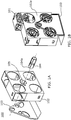
- FIG. 1A shows a front view of an example of a cooling system 100 according to the present disclosure.
- the cooling system 100 comprises a fan cage 102, the fan cage 102 comprises a cavity 105 on its central axis, a support bracket 103 and a bush 104.
- the bush 104 comprises a first end 104a.
- the support bracket 103 can support the fan cage 102 such that the fan cage rotates on its central axis.
- the central axis of the fan cage may be located in the middle length and width of the square fan cage.
- the fan cage 102 is a square fan cage.
- the fan cage 102 can have other shapes, as e.g. a rectangle, pentagon, hexagon, etc.
- the selected shape of the fan cage may permit the rotation of the fan cage on its central axis.
- FIG. 1B shows a rear view of the cooling system 100 comprising a plurality of adjacent fan modules 101.
- the plurality of adjacent fan modules 101 can be configured to generate a plurality of independent cooling flows.
- the fan cage 102 having a central axis can contain the plurality of adjacent fan modules 101.
- the bush 104 is established in the cavity 105 of the fan cage 102 as shown in FIG. 1B .
- the first end 104a of the bush 104 engages the support bracket 103 on a surface 102a of the fan cage 102.
- the cooling system 100 can be used to cool devices as storage drives.
- the storage drives can include solid state drives (SSDs), hard disk drives, etc.
- SSDs solid state drives
- the storage drives can be contained in an enclosure as e.g. a storage server system. These types of enclosures can store a large number of devices that must to be cooled to work properly.
- the present disclosure also relates to a server system comprising a plurality of devices cooled by a cooling system as the example shown in FIG. 1B .
- FIG. 2A shows elements of an example of a cooling system 200 according to the present disclosure.
- FIG. 2A shows a fan cage 202 having a central axis and comprising four compartments 209a to 209d that can contain four fan modules (not shown). Furthermore, the fan cage 202 comprises a cavity 205 located in the central axis of the fan cage 202.
- FIG. 2A also shows four electrical cables 206 (e.g. fan cables) attached to four electrical connectors 207, respectively.
- the electrical cables 206 can connect the fan modules via the electrical connectors 207 to a computing device (not shown) to the cooling system 200.
- a computing device can be e.g. a storage server.
- a server system comprises a cooling system according to this disclosure, wherein the cooling system further comprises one or more electrical connectors to connect the plurality of fan modules to the plurality of electrical cables.
- the cooling system 200 further shows a bush 204 comprising a hollow cavity that can contain a junction point 208 of the electrical cables 206. Furthermore the bush 204 comprises four holes 210 established on the bush surface to route the electrical cables 206 outside the bush 204.
- FIG. 2A shows the electrical cables 206 inserted in the bush 204.
- the integration of the electrical cables 206 and the bush 204 with the fan cage 202 is also shown in FIG. 2A .
- the power supply can be provided by a power source located in a storage server that includes the cooling system 200.
- the power can be supplied by external electrical cables through the bush 204 where the electrical cables 206 are established and routed along the fan cage 202.
- FIG. 2B shows the same example cooling system 200 of FIG. 2A but with cage 202 being transparent.
- the transparent cage shows a plurality of channels that for in this particular example form they form a cross-shaped channel 211 located inside the fan cage 202.
- the crops-shaped channel 211 routes the electrical cables 206 through the fan cage 202 as it can be seen in the integration of the electrical cables 206 and the bush 204 with the fan cage 202 and the cross-shaped channel 211 in FIG. 2B .
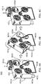
- FIGS. 3A to 3C show a cooling system 300 comprising a fan cage 302 with four compartments 309a to 309d that can allocate four fan modules 301 a to 301 d, respectively.
- FIG. 3A shows how the fan module 301 a is installed into the compartment 309a.
- the compartment 309a has an access point or entrance that permits the installation or removal of the fan module 301 a.
- the installation of the fan module 301 a can be carried out without interrupting the enclosure of other fan modules 301 b to 301 d allocated in the fan cage 302 and without interrupting the functioning of e.g. a modular server being serviced by the cooling system.
- FIG. 3B shows the process of rotating the fan cage 302 around the central axis of the fan cage 302 to access the compartment 309d in order to install an additional fan module 301 d as shown in FIG. 3C .
- FIG. 3C shows that the compartment 309d can be accessed and the fan module 301 d can be installed into the compartment 309d by a user or operator of the cooling system by means of rotating the fan cage 302.
- a first advantage of the proposed cooling system by rotating the fan cage 302 during installation of a new fan module is that none of the remaining fan modules, e.g. 301 b and 301 c have to be interrupted in order to install a new fan module 301 d.
- a second advantage of the proposed cooling system by rotating the fan cage 302 during replacement of a faulty fan module is that only the faulty fan module must be interrupted in order to install a new fan module.
- a third advantage of the proposed cooling system is that an associated computing device as e.g. a modular server may not have to be interrupted during replacement, installation or removal of any fan module.
- FIG. 4 shows another example of a cooling system 400 according to the present disclosure.
- the cooling system 400 comprises a fan cage 402 having a first surface 402a and a second surface 402b and a central cavity that allocates a bush (not shown).
- the cooling system 400 further comprises a first support bracket 403a that can engage a first end of a bush on the first surface 402a.
- the cooling system 400 further comprises a second support bracket 403b that can engage a second end of the bush on the second surface 402b of the fan cage 402.
- FIGS. 1 to 4 The rotation capabilities of the proposed fan cages shown in FIGS. 1 to 4 permit that any fan module can be installed, removed or replaced without interrupting the enclosure and functioning of other fan modules allocated in the fan cage and the functioning of a device e.g. a modular server associated and/or being serviced by the cooling system.
- a device e.g. a modular server associated and/or being serviced by the cooling system.
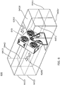
- FIG. 5 shows a top view of a system 500 comprising a cooling system 510 and devices 540.
- the devices 540 can include storage drives as e.g. hard drives, solid state drives (SSD), and/or other components that generate heat (e.g., a processor, memory, etc.).
- the server system 500 comprises an example of a cooling system 510 as shown in the previous figures and according to the present disclosure.
- the cooling system 510 comprises four adjacent fan modules 511 configured to generate a plurality of independent cooling flows 520 to cool the devices 540.
- FIG. 5 shows a top view of the cooling system 510 comprising fan modules 511 a and 511b within a fan cage 512.
- the cooling system 510 comprises a fan cage 512 having a central axis.
- the fan cage 512 can contain the fan modules 511.
- the fan cage 512 comprises a cavity on its central axis.
- a support bracket not shown can support the fan cage 512 such that the fan cage rotates on its central axis.
- a bush 514 is established in the cavity of the fan cage 512.
- a part of the bush 514 can engage the support bracket to permit the fan cage 512 to rotate.
- a plurality of electrical cables 516 from a power source 530 can power the fan modules 511 via the bush 514.
- the server system can be a modular server as a rack server.
- the cooling system can further comprise a second support bracket, wherein a part of the bush 514 is adapted to engage the second support bracket.
- FIG.6 shows an example of a cooling system 600 according to present disclosure.
- the cooling system 600 can generate an upstream cooling flow 620U and a downstream cooling flow 620D.
- the upstream cooling flow 620U can cool quadrants 641 U, 642U, 643U and 644U facing a first side of the cooling system 600.
- the downstream cooling flow 620D can cool quadrants 641 D, 642D, 643D and 644D facing a second side of the cooling system 600.
- Each quadrant cooled by the upstream cooling flow 620U can contain a device or an enclosure (e.g. a storage server) for several devices.
- Each quadrant cooled by the downstream cooling flow 620D can contain a device or an enclosure (e.g. a storage server) for several devices.
- the devices can comprise heat generating components such as processors, memory, voltage regulators, storage drives as e.g. hard drives, solid state drives (SSD), etc.
- An advantage of the proposed cooling systems according to the present disclosure can be that the cooling system 600 can provide independent cooling to devices/enclosures located in different quadrants in the upstream cooling flow 620U and/or in the downstream cooling flow 620D.
- the cooling of devices/enclosures located in quadrants not affected by the replacement of the (faulty) fan module and being cooled by the remaining fan modules may not be interrupted.
- FIG. 7 illustrates an example of a flowchart 700 for accessing a cooling system according to the present disclosure, in particular FIG. 7 shows steps for accessing a predetermined fan module from a plurality of fan modules in a cooling system.
- the flowchart 700 comprises step 710 for rotating a fan cage having a central axis, the fan cage comprising a plurality of fan modules allocated in compartments with access points or gates for accessing the fan modules.
- the fan modules can be distributed around the central axis of the fan cage as shown in FIGS. 3 and 4 .
- the flowchart 700 comprises step 720 for reaching an access point of the predetermined fan module by rotating the fan cage.
- Each fan module associated with a fan cable that powers the fan module.
- the rotation of the fan cage is shows in FIGS. 3 and 4 .
- the fan cage can be rotated by a user or an operator in order to access a predetermined fan module or compartment within the fan cage.
- the flowchart 700 comprises step 730 for accessing the predetermined fan module.
- FIGS. 3C and 4C show how a particular compartment can be accessed in order to install a new fan module without interrupting the enclosure and the functioning of other fan modules or associated computing devices due to the rotation capabilities of the proposed cooling system.
- the flowchart 700 comprises a step for removing the predetermined fan module from the fan cage via the access point.
- a predetermine fan module can be removed from the fan cage by accessing by rotating the fan cage and reach the predetermined fan module to be removed.
- the flowchart 700 comprises a step for installing a new fan module in place of the removed predetermined fan module via the access point by attaching the fan cable of the removed fan module to the new fan module.
- the predetermined fan module is a faulty fan module.
- a faulty fan module can be removed and a new fan module can be installed or inserted into a free compartment within the fan cage according to the examples of cooling systems shown in the present disclosure.
Landscapes
- Engineering & Computer Science (AREA)
- Microelectronics & Electronic Packaging (AREA)
- General Engineering & Computer Science (AREA)
- Mechanical Engineering (AREA)
- Physics & Mathematics (AREA)
- Thermal Sciences (AREA)
- Computer Hardware Design (AREA)
- Aviation & Aerospace Engineering (AREA)
- Cooling Or The Like Of Electrical Apparatus (AREA)
Abstract
Description
- Server systems are generally shaped and sized based on industry standards. To maximize storage capacity of servers, storage devices are tightly packed side by side within an enclosure. Such servers have very little space for air movement between each storage device. Thus, it will be understood that placing a large number of storage devices close together can introduce cooling issues. Furthermore, storage devices may require independent cooling which should not be interrupted due to the manipulation of a cooling system designed to overcome the cooling issues. Hence, an efficient cooling system that solves the mentioned drawbacks is desired.
-
-
FIG. 1A and 1B illustrate an example of a cooling system according to the present disclosure. -
FIGS. 2A and 2B illustrate elements of an example of a cooling system according to the present disclosure. -
FIGS. 3A, 3B and 3C illustrate an example of a cooling system according to the present disclosure. -
FIGS. 4A, 4B and 4C illustrate another example of a cooling system according to the present disclosure. -
FIG. 5 illustrates an example of a system according to the present disclosure. -
FIG. 6 illustrates an example of a cooling system according to the present disclosure. -
FIG. 7 illustrates an example of a flowchart for accessing a cooling system according to the present disclosure. - Many servers utilize conventional cooling systems to remove the heat from disk drives and controlling electronics. Such cooling systems are designed to move a large volume of air across or throughout the server in order to remove the heat energy created by the operation of the server.
- Effective air flow mass movement generally requires open spaces between and around storage drives and surrounding electronics throughout the server system. Examples of server systems can be e.g. a modular server as a rack server. At the same time, it should be desirable to have size efficient enclosures where the volume of the enclosure is minimized as much as possible and that could permit the replacement of a faulty fan without interrupting the enclosure and the functioning of other devices. The present disclosure proposes a cooling system that at least solves the aforementioned drawbacks.
-
FIG. 1A shows a front view of an example of acooling system 100 according to the present disclosure. Thecooling system 100 comprises afan cage 102, thefan cage 102 comprises acavity 105 on its central axis, asupport bracket 103 and abush 104. Thebush 104 comprises afirst end 104a. Thesupport bracket 103 can support thefan cage 102 such that the fan cage rotates on its central axis. The central axis of the fan cage may be located in the middle length and width of the square fan cage. In this example, thefan cage 102 is a square fan cage. In some implementations, thefan cage 102 can have other shapes, as e.g. a rectangle, pentagon, hexagon, etc. The selected shape of the fan cage may permit the rotation of the fan cage on its central axis. -
FIG. 1B shows a rear view of thecooling system 100 comprising a plurality ofadjacent fan modules 101. The plurality ofadjacent fan modules 101 can be configured to generate a plurality of independent cooling flows. Thefan cage 102 having a central axis can contain the plurality ofadjacent fan modules 101. Thebush 104 is established in thecavity 105 of thefan cage 102 as shown inFIG. 1B . Thefirst end 104a of thebush 104 engages thesupport bracket 103 on asurface 102a of thefan cage 102. - The
cooling system 100 can be used to cool devices as storage drives. The storage drives can include solid state drives (SSDs), hard disk drives, etc. The storage drives can be contained in an enclosure as e.g. a storage server system. These types of enclosures can store a large number of devices that must to be cooled to work properly. Hence, the present disclosure also relates to a server system comprising a plurality of devices cooled by a cooling system as the example shown inFIG. 1B . -
FIG. 2A shows elements of an example of acooling system 200 according to the present disclosure.FIG. 2A shows afan cage 202 having a central axis and comprising fourcompartments 209a to 209d that can contain four fan modules (not shown). Furthermore, thefan cage 202 comprises acavity 205 located in the central axis of thefan cage 202. -
FIG. 2A also shows four electrical cables 206 (e.g. fan cables) attached to fourelectrical connectors 207, respectively. Theelectrical cables 206 can connect the fan modules via theelectrical connectors 207 to a computing device (not shown) to thecooling system 200. An example of a computing device can be e.g. a storage server. In an example, a server system comprises a cooling system according to this disclosure, wherein the cooling system further comprises one or more electrical connectors to connect the plurality of fan modules to the plurality of electrical cables. - The
cooling system 200 further shows abush 204 comprising a hollow cavity that can contain ajunction point 208 of theelectrical cables 206. Furthermore thebush 204 comprises fourholes 210 established on the bush surface to route theelectrical cables 206 outside thebush 204. -
FIG. 2A shows theelectrical cables 206 inserted in thebush 204. The integration of theelectrical cables 206 and thebush 204 with thefan cage 202 is also shown inFIG. 2A . The power supply can be provided by a power source located in a storage server that includes thecooling system 200. The power can be supplied by external electrical cables through thebush 204 where theelectrical cables 206 are established and routed along thefan cage 202. -
FIG. 2B shows the sameexample cooling system 200 ofFIG. 2A but withcage 202 being transparent. The transparent cage shows a plurality of channels that for in this particular example form they form across-shaped channel 211 located inside thefan cage 202. The crops-shapedchannel 211 routes theelectrical cables 206 through thefan cage 202 as it can be seen in the integration of theelectrical cables 206 and thebush 204 with thefan cage 202 and thecross-shaped channel 211 inFIG. 2B . -
FIGS. 3A to 3C show acooling system 300 comprising afan cage 302 with fourcompartments 309a to 309d that can allocate fourfan modules 301 a to 301 d, respectively.FIG. 3A shows how thefan module 301 a is installed into thecompartment 309a. Thecompartment 309a has an access point or entrance that permits the installation or removal of thefan module 301 a. The installation of thefan module 301 a can be carried out without interrupting the enclosure ofother fan modules 301 b to 301 d allocated in thefan cage 302 and without interrupting the functioning of e.g. a modular server being serviced by the cooling system. -
FIG. 3B shows the process of rotating thefan cage 302 around the central axis of thefan cage 302 to access thecompartment 309d in order to install anadditional fan module 301 d as shown inFIG. 3C . Hence,FIG. 3C shows that thecompartment 309d can be accessed and thefan module 301 d can be installed into thecompartment 309d by a user or operator of the cooling system by means of rotating thefan cage 302. A first advantage of the proposed cooling system by rotating thefan cage 302 during installation of a new fan module is that none of the remaining fan modules, e.g. 301 b and 301 c have to be interrupted in order to install anew fan module 301 d. A second advantage of the proposed cooling system by rotating thefan cage 302 during replacement of a faulty fan module is that only the faulty fan module must be interrupted in order to install a new fan module. A third advantage of the proposed cooling system is that an associated computing device as e.g. a modular server may not have to be interrupted during replacement, installation or removal of any fan module. -
FIG. 4 shows another example of acooling system 400 according to the present disclosure. Thecooling system 400 comprises afan cage 402 having afirst surface 402a and asecond surface 402b and a central cavity that allocates a bush (not shown). Thecooling system 400 further comprises afirst support bracket 403a that can engage a first end of a bush on thefirst surface 402a. Thecooling system 400 further comprises asecond support bracket 403b that can engage a second end of the bush on thesecond surface 402b of thefan cage 402. - The rotation capabilities of the proposed fan cages shown in
FIGS. 1 to 4 permit that any fan module can be installed, removed or replaced without interrupting the enclosure and functioning of other fan modules allocated in the fan cage and the functioning of a device e.g. a modular server associated and/or being serviced by the cooling system. -
FIG. 5 shows a top view of asystem 500 comprising acooling system 510 anddevices 540. Thedevices 540 can include storage drives as e.g. hard drives, solid state drives (SSD), and/or other components that generate heat (e.g., a processor, memory, etc.). Theserver system 500 comprises an example of acooling system 510 as shown in the previous figures and according to the present disclosure. Thecooling system 510 comprises four adjacent fan modules 511 configured to generate a plurality of independent cooling flows 520 to cool thedevices 540. - In particular,
FIG. 5 shows a top view of thecooling system 510 comprisingfan modules fan cage 512. Thecooling system 510 comprises afan cage 512 having a central axis. Thefan cage 512 can contain the fan modules 511. Furthermore, thefan cage 512 comprises a cavity on its central axis. A support bracket not shown can support thefan cage 512 such that the fan cage rotates on its central axis. - Furthermore, a bush 514 is established in the cavity of the
fan cage 512. A part of the bush 514 can engage the support bracket to permit thefan cage 512 to rotate. A plurality ofelectrical cables 516 from apower source 530 can power the fan modules 511 via the bush 514. In some implementations, the server system can be a modular server as a rack server. In some implementations, the cooling system can further comprise a second support bracket, wherein a part of the bush 514 is adapted to engage the second support bracket. -
FIG.6 shows an example of acooling system 600 according to present disclosure. Thecooling system 600 can generate anupstream cooling flow 620U and adownstream cooling flow 620D. Theupstream cooling flow 620U can coolquadrants cooling system 600. Thedownstream cooling flow 620D can coolquadrants cooling system 600. Each quadrant cooled by theupstream cooling flow 620U can contain a device or an enclosure (e.g. a storage server) for several devices. Each quadrant cooled by thedownstream cooling flow 620D can contain a device or an enclosure (e.g. a storage server) for several devices. The devices can comprise heat generating components such as processors, memory, voltage regulators, storage drives as e.g. hard drives, solid state drives (SSD), etc. - An advantage of the proposed cooling systems according to the present disclosure can be that the
cooling system 600 can provide independent cooling to devices/enclosures located in different quadrants in theupstream cooling flow 620U and/or in thedownstream cooling flow 620D. As mentioned in previousFIG.3 during the replacement of a (faulty) fan module only the (faulty) fan module must be interrupted in order to install a new fan module in the cooling system while the remaining fan modules continue to function. Hence, the cooling of devices/enclosures located in quadrants not affected by the replacement of the (faulty) fan module and being cooled by the remaining fan modules may not be interrupted. -
FIG. 7 illustrates an example of aflowchart 700 for accessing a cooling system according to the present disclosure, in particularFIG. 7 shows steps for accessing a predetermined fan module from a plurality of fan modules in a cooling system. - The
flowchart 700 comprisesstep 710 for rotating a fan cage having a central axis, the fan cage comprising a plurality of fan modules allocated in compartments with access points or gates for accessing the fan modules. The fan modules can be distributed around the central axis of the fan cage as shown inFIGS. 3 and4 . - The
flowchart 700 comprisesstep 720 for reaching an access point of the predetermined fan module by rotating the fan cage. Each fan module associated with a fan cable that powers the fan module. - The rotation of the fan cage is shows in
FIGS. 3 and4 . The fan cage can be rotated by a user or an operator in order to access a predetermined fan module or compartment within the fan cage. - The
flowchart 700 comprisesstep 730 for accessing the predetermined fan module. In particular,FIGS. 3C and4C show how a particular compartment can be accessed in order to install a new fan module without interrupting the enclosure and the functioning of other fan modules or associated computing devices due to the rotation capabilities of the proposed cooling system. - Furthermore, the
flowchart 700 comprises a step for removing the predetermined fan module from the fan cage via the access point. A predetermine fan module can be removed from the fan cage by accessing by rotating the fan cage and reach the predetermined fan module to be removed. - The
flowchart 700 comprises a step for installing a new fan module in place of the removed predetermined fan module via the access point by attaching the fan cable of the removed fan module to the new fan module. In an example, the predetermined fan module is a faulty fan module. A faulty fan module can be removed and a new fan module can be installed or inserted into a free compartment within the fan cage according to the examples of cooling systems shown in the present disclosure. - Furthermore, relative terms used to describe the structural features of the figures illustrated herein are in no way limiting to conceivable implementations. It is, of course, not possible to describe every conceivable combination of components or methods, but one of ordinary skill in the art will recognize that many further combinations and permutations are possible. Accordingly, the invention is intended to embrace all such alterations, modifications, and variations that fall within the scope of this application, including the appended claims. Additionally, where the disclosure or claims recite "a," "an," "a first," or "another" element, or the equivalent thereof, it should be interpreted to include one or more than one such element, neither requiring nor excluding two or more such elements.
Claims (15)
- A cooling system, the system comprising:a plurality of adjacent fan modules configured to generate a plurality of cooling flows;a fan cage having a central axis adapted to contain the plurality of adjacent fan modules, the fan cage comprising a cavity on its central axis;a first support bracket adapted to support the fan cage such that the fan cage rotates on its central axis; anda bush established in the cavity of the fan cage,
wherein a first end of the bush is adapted to engage the first support bracket on a first surface of the fan cage. - The cooling system according to claim 1, further comprising a plurality of electrical cables to power the fan modules via the bush.
- The cooling system according to claim 2, wherein the fan cage comprises:a plurality of compartments adapted to contain the fan modules; anda plurality of channels adapted to route the electrical cables.
- The cooling system according to claim 3, wherein the bush comprises:a hollow cavity adapted to contain a junction point of the electrical cables; andone or more holes established on the bush surface to route the electrical cables.
- The cooling system according to claim 2, wherein the plurality of electrical cables comprises one or more electrical connectors.
- The cooling system according to claim 1, wherein the plurality of adjacent fan modules comprises four fan modules.
- The cooling system according to claim 1, further comprising a second support bracket, wherein a second end of the bush is adapted to engage the second support bracket on a second surface of the fan cage opposite to the first surface.
- A server system, the system comprising:a plurality of devices;a cooling system according to any of the above claims; anda plurality of electrical cables from a power source to power the fan modules through the bush,wherein the cooling system is adapted to cool the plurality of devices.
- The server system of claim 8, wherein the plurality of devices are storage devices.
- The server system of claim 8, wherein the cooling system comprises four fan modules configured to generate a plurality of independent cooling flows.
- The server system of claim 8, including an enclosure that includes the plurality of devices and the cooling system.
- A method for accessing a predetermined fan module from a plurality of fan modules in a cooling system, the method comprising:rotating a fan cage having a central axis, the fan cage comprising the plurality of fan modules and access points for the fan modules, the fan modules being distributed around said central axis,wherein each fan module is associated with a fan cable that powers the fan module;reaching an access point of the predetermined fan module by rotating the fan cage; andaccessing the predetermined fan module.
- The method of claim 12, further comprising:
removing the predetermined fan module from the fan cage via the access point. - The method of claim 12, further comprising:
installing a new fan module in place of the removed predetermined fan module via the access point by attaching a fan cable of the removed fan module to the new fan module. - The method of claims 14, wherein the predetermined fan module is faulty.
Applications Claiming Priority (1)
| Application Number | Priority Date | Filing Date | Title |
|---|---|---|---|
| US15/496,138 US10888020B2 (en) | 2017-04-25 | 2017-04-25 | Cooling systems |
Publications (2)
| Publication Number | Publication Date |
|---|---|
| EP3397038A1 true EP3397038A1 (en) | 2018-10-31 |
| EP3397038B1 EP3397038B1 (en) | 2021-12-22 |
Family
ID=62062932
Family Applications (1)
| Application Number | Title | Priority Date | Filing Date |
|---|---|---|---|
| EP18169045.4A Not-in-force EP3397038B1 (en) | 2017-04-25 | 2018-04-24 | Cooling systems |
Country Status (2)
| Country | Link |
|---|---|
| US (1) | US10888020B2 (en) |
| EP (1) | EP3397038B1 (en) |
Families Citing this family (1)
| Publication number | Priority date | Publication date | Assignee | Title |
|---|---|---|---|---|
| CN119982667B (en) * | 2025-02-10 | 2026-02-03 | 上海昭晟机电(江苏)有限公司 | Quick replacement method for cooling fan module of foil producing machine |
Citations (5)
| Publication number | Priority date | Publication date | Assignee | Title |
|---|---|---|---|---|
| US7408774B1 (en) * | 2007-03-06 | 2008-08-05 | International Business Machines Corporation | Real time adaptive active fluid flow cooling |
| US8320120B1 (en) * | 2008-12-19 | 2012-11-27 | Hewlett-Packard Development Company, L.P. | Reversible air flow fan system |
| US20130109288A1 (en) * | 2011-10-26 | 2013-05-02 | Hon Hai Precision Industry Co., Ltd. | Fan module and cabinet having the same |
| US20150351280A1 (en) * | 2014-05-29 | 2015-12-03 | Arris Enterprises, Inc. | Pivotable Fan Assembly and Associated Systems |
| US20160174409A1 (en) * | 2014-12-15 | 2016-06-16 | Intel Corporation | Reversible fan assembly |
Family Cites Families (35)
| Publication number | Priority date | Publication date | Assignee | Title |
|---|---|---|---|---|
| US2733002A (en) * | 1956-01-31 | twin window fans | ||
| US2108738A (en) * | 1937-03-12 | 1938-02-15 | William W Allen | Twin-fan structure |
| US2830779A (en) * | 1955-02-21 | 1958-04-15 | Lau Blower Co | Fan stand |
| JPS52140505A (en) | 1976-05-19 | 1977-11-24 | Cities Service Co | Hydrogenation method of carbonaceous material |
| JPS5683599A (en) * | 1979-12-11 | 1981-07-08 | Matsushita Seiko Co Ltd | Electric fan |
| US6373698B1 (en) * | 2001-05-03 | 2002-04-16 | International Business Machines Corporation | Apparatus for cooling a computer system |
| US6826456B1 (en) | 2001-05-04 | 2004-11-30 | Rlx Technologies, Inc. | System and method for controlling server chassis cooling fans |
| US6690576B2 (en) | 2001-07-31 | 2004-02-10 | Hewlett Packard Development Company, L.P. | Externally mounted on-line replaceable fan module |
| US6714411B2 (en) | 2001-12-31 | 2004-03-30 | Hewlett-Packard Development Company, L.P. | Computer server hot plug fan tray assembly and method of fan removal |
| US6878874B2 (en) | 2002-06-10 | 2005-04-12 | Sun Microsystems, Inc. | Electronics assembly |
| US6682308B1 (en) * | 2002-08-01 | 2004-01-27 | Kaz, Inc. | Fan with adjustable mount |
| US6752587B2 (en) * | 2002-08-07 | 2004-06-22 | Inventec Corporation | Modular fan assembly |
| US7054155B1 (en) * | 2003-03-17 | 2006-05-30 | Unisys Corporation | Fan tray assembly |
| JP2006002762A (en) * | 2004-05-18 | 2006-01-05 | Nippon Densan Corp | Blower |
| US7406835B2 (en) * | 2005-05-10 | 2008-08-05 | Emp Advanced Development, Llc | Cooling system and method for cooling a heat producing system |
| US7542272B2 (en) * | 2005-09-30 | 2009-06-02 | Dell Products L.P. | Rotatable cooling fans and method for use |
| US20080286114A1 (en) * | 2007-05-17 | 2008-11-20 | Minka Lighting Inc. | Portable fan |
| US7640897B2 (en) * | 2007-08-08 | 2010-01-05 | Sauer-Danfoss, Inc. | Fan design and method of operating |
| TWM341877U (en) * | 2007-10-24 | 2008-10-01 | Akust Technology Co Ltd | Heat sink fan stand for memory card |
| US8186941B2 (en) * | 2008-03-20 | 2012-05-29 | Air Cool Industrial Co., Ltd. | Swing structure for a ceiling fan |
| DE112009001556T5 (en) * | 2008-06-23 | 2011-04-28 | Milwaukee Electric Tool Corp., Brookfield | Electrical arrangement with a battery charging function |
| CN102022361A (en) * | 2009-09-14 | 2011-04-20 | 鸿富锦精密工业(深圳)有限公司 | Fan combination |
| TW201122764A (en) | 2009-12-21 | 2011-07-01 | Hon Hai Prec Ind Co Ltd | Server system and server thereof |
| CN102650297A (en) * | 2011-02-24 | 2012-08-29 | 鸿富锦精密工业(深圳)有限公司 | Heat dissipation device |
| US9017020B2 (en) | 2011-02-28 | 2015-04-28 | Cisco Technology, Inc. | Configurable fan unit |
| CN102759969A (en) | 2011-04-25 | 2012-10-31 | 鸿富锦精密工业(深圳)有限公司 | Fan fixing device |
| US8631665B1 (en) * | 2011-06-27 | 2014-01-21 | Anthony DeClementi | Portable cooling device |
| US9163845B1 (en) * | 2011-08-10 | 2015-10-20 | D. George Carlozzi | Garage ventilation system |
| TW201328478A (en) | 2011-12-20 | 2013-07-01 | Inventec Corp | Server |
| US20130315727A1 (en) * | 2012-05-24 | 2013-11-28 | Edwin Ho | Stackable fan |
| JP6009856B2 (en) * | 2012-08-03 | 2016-10-19 | 日本電産サーボ株式会社 | Rotating electric machine |
| CN202975956U (en) | 2012-12-03 | 2013-06-05 | 浪潮电子信息产业股份有限公司 | Rotatable server fan frame |
| JP5705277B2 (en) | 2013-08-09 | 2015-04-22 | 新日鉄住金エンジニアリング株式会社 | Server rack indoor system |
| CN104423480A (en) | 2013-08-28 | 2015-03-18 | 鸿富锦精密工业(深圳)有限公司 | Server cabinet and cooling system |
| US10231361B2 (en) | 2015-07-30 | 2019-03-12 | Quanta Computer Inc. | Fan system management |
-
2017
- 2017-04-25 US US15/496,138 patent/US10888020B2/en not_active Expired - Fee Related
-
2018
- 2018-04-24 EP EP18169045.4A patent/EP3397038B1/en not_active Not-in-force
Patent Citations (5)
| Publication number | Priority date | Publication date | Assignee | Title |
|---|---|---|---|---|
| US7408774B1 (en) * | 2007-03-06 | 2008-08-05 | International Business Machines Corporation | Real time adaptive active fluid flow cooling |
| US8320120B1 (en) * | 2008-12-19 | 2012-11-27 | Hewlett-Packard Development Company, L.P. | Reversible air flow fan system |
| US20130109288A1 (en) * | 2011-10-26 | 2013-05-02 | Hon Hai Precision Industry Co., Ltd. | Fan module and cabinet having the same |
| US20150351280A1 (en) * | 2014-05-29 | 2015-12-03 | Arris Enterprises, Inc. | Pivotable Fan Assembly and Associated Systems |
| US20160174409A1 (en) * | 2014-12-15 | 2016-06-16 | Intel Corporation | Reversible fan assembly |
Also Published As
| Publication number | Publication date |
|---|---|
| US20180310432A1 (en) | 2018-10-25 |
| US10888020B2 (en) | 2021-01-05 |
| EP3397038B1 (en) | 2021-12-22 |
Similar Documents
| Publication | Publication Date | Title |
|---|---|---|
| US10757838B2 (en) | System and method for data center heat containment | |
| AU2009338698B2 (en) | Hot aisle containment cooling system and method | |
| US6525935B2 (en) | Low profile highly accessible computer enclosure with plenum for cooling high power processors | |
| US10130018B2 (en) | Compute node cooling with air fed through backplane | |
| US20140185225A1 (en) | Advanced Datacenter Designs | |
| US20160157389A1 (en) | Container data center | |
| US9920772B2 (en) | Reversible fan module | |
| CN104053339A (en) | Electrical cabinet with improved heat dissipation | |
| CN106464523A (en) | Flexible data center infrastructure distribution | |
| US9439329B1 (en) | Inflatable data center | |
| US8898682B2 (en) | Cooling in high-density storage systems | |
| US10485140B2 (en) | Air distribution units for telecommunication equipment | |
| US10751658B2 (en) | External rack mounted filter for network device | |
| US8028793B2 (en) | Noise attenuating inserts for electronic equipment cabinets | |
| CN105379439B (en) | Modular data center | |
| EP3397038B1 (en) | Cooling systems | |
| TW201714041A (en) | Server rack assembly and temperature controlling method | |
| US9131624B1 (en) | Rack-mountable IT device | |
| US10334762B2 (en) | Movable rack | |
| US10206313B1 (en) | Systems and methods for configuring information technology racks | |
| EP3508947A1 (en) | Rear side swappable fan array module design | |
| US9839161B2 (en) | Thermal ducting for improved cooling in rack domains | |
| EP3514660B1 (en) | System for compute node maintenance with continuous cooling | |
| US20210259139A1 (en) | Crossflow air cooling module for electronic equipment |
Legal Events
| Date | Code | Title | Description |
|---|---|---|---|
| PUAI | Public reference made under article 153(3) epc to a published international application that has entered the european phase |
Free format text: ORIGINAL CODE: 0009012 |
|
| STAA | Information on the status of an ep patent application or granted ep patent |
Free format text: STATUS: THE APPLICATION HAS BEEN PUBLISHED |
|
| AK | Designated contracting states |
Kind code of ref document: A1 Designated state(s): AL AT BE BG CH CY CZ DE DK EE ES FI FR GB GR HR HU IE IS IT LI LT LU LV MC MK MT NL NO PL PT RO RS SE SI SK SM TR |
|
| AX | Request for extension of the european patent |
Extension state: BA ME |
|
| RAP1 | Party data changed (applicant data changed or rights of an application transferred) |
Owner name: HEWLETT PACKARD ENTERPRISE DEVELOPMENT LP |
|
| STAA | Information on the status of an ep patent application or granted ep patent |
Free format text: STATUS: REQUEST FOR EXAMINATION WAS MADE |
|
| 17P | Request for examination filed |
Effective date: 20190215 |
|
| RBV | Designated contracting states (corrected) |
Designated state(s): AL AT BE BG CH CY CZ DE DK EE ES FI FR GB GR HR HU IE IS IT LI LT LU LV MC MK MT NL NO PL PT RO RS SE SI SK SM TR |
|
| GRAP | Despatch of communication of intention to grant a patent |
Free format text: ORIGINAL CODE: EPIDOSNIGR1 |
|
| STAA | Information on the status of an ep patent application or granted ep patent |
Free format text: STATUS: GRANT OF PATENT IS INTENDED |
|
| RIC1 | Information provided on ipc code assigned before grant |
Ipc: H05K 7/20 20060101AFI20210330BHEP |
|
| INTG | Intention to grant announced |
Effective date: 20210422 |
|
| GRAJ | Information related to disapproval of communication of intention to grant by the applicant or resumption of examination proceedings by the epo deleted |
Free format text: ORIGINAL CODE: EPIDOSDIGR1 |
|
| STAA | Information on the status of an ep patent application or granted ep patent |
Free format text: STATUS: REQUEST FOR EXAMINATION WAS MADE |
|
| INTC | Intention to grant announced (deleted) | ||
| GRAP | Despatch of communication of intention to grant a patent |
Free format text: ORIGINAL CODE: EPIDOSNIGR1 |
|
| STAA | Information on the status of an ep patent application or granted ep patent |
Free format text: STATUS: GRANT OF PATENT IS INTENDED |
|
| GRAS | Grant fee paid |
Free format text: ORIGINAL CODE: EPIDOSNIGR3 |
|
| INTG | Intention to grant announced |
Effective date: 20211018 |
|
| GRAA | (expected) grant |
Free format text: ORIGINAL CODE: 0009210 |
|
| STAA | Information on the status of an ep patent application or granted ep patent |
Free format text: STATUS: THE PATENT HAS BEEN GRANTED |
|
| AK | Designated contracting states |
Kind code of ref document: B1 Designated state(s): AL AT BE BG CH CY CZ DE DK EE ES FI FR GB GR HR HU IE IS IT LI LT LU LV MC MK MT NL NO PL PT RO RS SE SI SK SM TR |
|
| REG | Reference to a national code |
Ref country code: GB Ref legal event code: FG4D |
|
| REG | Reference to a national code |
Ref country code: CH Ref legal event code: EP |
|
| REG | Reference to a national code |
Ref country code: DE Ref legal event code: R096 Ref document number: 602018028408 Country of ref document: DE |
|
| REG | Reference to a national code |
Ref country code: AT Ref legal event code: REF Ref document number: 1457978 Country of ref document: AT Kind code of ref document: T Effective date: 20220115 |
|
| REG | Reference to a national code |
Ref country code: IE Ref legal event code: FG4D |
|
| REG | Reference to a national code |
Ref country code: LT Ref legal event code: MG9D |
|
| PG25 | Lapsed in a contracting state [announced via postgrant information from national office to epo] |
Ref country code: RS Free format text: LAPSE BECAUSE OF FAILURE TO SUBMIT A TRANSLATION OF THE DESCRIPTION OR TO PAY THE FEE WITHIN THE PRESCRIBED TIME-LIMIT Effective date: 20211222 Ref country code: LT Free format text: LAPSE BECAUSE OF FAILURE TO SUBMIT A TRANSLATION OF THE DESCRIPTION OR TO PAY THE FEE WITHIN THE PRESCRIBED TIME-LIMIT Effective date: 20211222 Ref country code: FI Free format text: LAPSE BECAUSE OF FAILURE TO SUBMIT A TRANSLATION OF THE DESCRIPTION OR TO PAY THE FEE WITHIN THE PRESCRIBED TIME-LIMIT Effective date: 20211222 Ref country code: BG Free format text: LAPSE BECAUSE OF FAILURE TO SUBMIT A TRANSLATION OF THE DESCRIPTION OR TO PAY THE FEE WITHIN THE PRESCRIBED TIME-LIMIT Effective date: 20220322 |
|
| PGFP | Annual fee paid to national office [announced via postgrant information from national office to epo] |
Ref country code: GB Payment date: 20220323 Year of fee payment: 5 |
|
| REG | Reference to a national code |
Ref country code: NL Ref legal event code: MP Effective date: 20211222 |
|
| REG | Reference to a national code |
Ref country code: AT Ref legal event code: MK05 Ref document number: 1457978 Country of ref document: AT Kind code of ref document: T Effective date: 20211222 |
|
| PG25 | Lapsed in a contracting state [announced via postgrant information from national office to epo] |
Ref country code: SE Free format text: LAPSE BECAUSE OF FAILURE TO SUBMIT A TRANSLATION OF THE DESCRIPTION OR TO PAY THE FEE WITHIN THE PRESCRIBED TIME-LIMIT Effective date: 20211222 Ref country code: NO Free format text: LAPSE BECAUSE OF FAILURE TO SUBMIT A TRANSLATION OF THE DESCRIPTION OR TO PAY THE FEE WITHIN THE PRESCRIBED TIME-LIMIT Effective date: 20220322 Ref country code: LV Free format text: LAPSE BECAUSE OF FAILURE TO SUBMIT A TRANSLATION OF THE DESCRIPTION OR TO PAY THE FEE WITHIN THE PRESCRIBED TIME-LIMIT Effective date: 20211222 Ref country code: HR Free format text: LAPSE BECAUSE OF FAILURE TO SUBMIT A TRANSLATION OF THE DESCRIPTION OR TO PAY THE FEE WITHIN THE PRESCRIBED TIME-LIMIT Effective date: 20211222 Ref country code: GR Free format text: LAPSE BECAUSE OF FAILURE TO SUBMIT A TRANSLATION OF THE DESCRIPTION OR TO PAY THE FEE WITHIN THE PRESCRIBED TIME-LIMIT Effective date: 20220323 |
|
| PG25 | Lapsed in a contracting state [announced via postgrant information from national office to epo] |
Ref country code: NL Free format text: LAPSE BECAUSE OF FAILURE TO SUBMIT A TRANSLATION OF THE DESCRIPTION OR TO PAY THE FEE WITHIN THE PRESCRIBED TIME-LIMIT Effective date: 20211222 |
|
| PG25 | Lapsed in a contracting state [announced via postgrant information from national office to epo] |
Ref country code: SM Free format text: LAPSE BECAUSE OF FAILURE TO SUBMIT A TRANSLATION OF THE DESCRIPTION OR TO PAY THE FEE WITHIN THE PRESCRIBED TIME-LIMIT Effective date: 20211222 Ref country code: SK Free format text: LAPSE BECAUSE OF FAILURE TO SUBMIT A TRANSLATION OF THE DESCRIPTION OR TO PAY THE FEE WITHIN THE PRESCRIBED TIME-LIMIT Effective date: 20211222 Ref country code: RO Free format text: LAPSE BECAUSE OF FAILURE TO SUBMIT A TRANSLATION OF THE DESCRIPTION OR TO PAY THE FEE WITHIN THE PRESCRIBED TIME-LIMIT Effective date: 20211222 Ref country code: PT Free format text: LAPSE BECAUSE OF FAILURE TO SUBMIT A TRANSLATION OF THE DESCRIPTION OR TO PAY THE FEE WITHIN THE PRESCRIBED TIME-LIMIT Effective date: 20220422 Ref country code: ES Free format text: LAPSE BECAUSE OF FAILURE TO SUBMIT A TRANSLATION OF THE DESCRIPTION OR TO PAY THE FEE WITHIN THE PRESCRIBED TIME-LIMIT Effective date: 20211222 Ref country code: EE Free format text: LAPSE BECAUSE OF FAILURE TO SUBMIT A TRANSLATION OF THE DESCRIPTION OR TO PAY THE FEE WITHIN THE PRESCRIBED TIME-LIMIT Effective date: 20211222 Ref country code: CZ Free format text: LAPSE BECAUSE OF FAILURE TO SUBMIT A TRANSLATION OF THE DESCRIPTION OR TO PAY THE FEE WITHIN THE PRESCRIBED TIME-LIMIT Effective date: 20211222 |
|
| PGFP | Annual fee paid to national office [announced via postgrant information from national office to epo] |
Ref country code: DE Payment date: 20220322 Year of fee payment: 5 |
|
| PG25 | Lapsed in a contracting state [announced via postgrant information from national office to epo] |
Ref country code: PL Free format text: LAPSE BECAUSE OF FAILURE TO SUBMIT A TRANSLATION OF THE DESCRIPTION OR TO PAY THE FEE WITHIN THE PRESCRIBED TIME-LIMIT Effective date: 20211222 Ref country code: AT Free format text: LAPSE BECAUSE OF FAILURE TO SUBMIT A TRANSLATION OF THE DESCRIPTION OR TO PAY THE FEE WITHIN THE PRESCRIBED TIME-LIMIT Effective date: 20211222 |
|
| REG | Reference to a national code |
Ref country code: DE Ref legal event code: R097 Ref document number: 602018028408 Country of ref document: DE |
|
| PG25 | Lapsed in a contracting state [announced via postgrant information from national office to epo] |
Ref country code: IS Free format text: LAPSE BECAUSE OF FAILURE TO SUBMIT A TRANSLATION OF THE DESCRIPTION OR TO PAY THE FEE WITHIN THE PRESCRIBED TIME-LIMIT Effective date: 20220422 |
|
| PLBE | No opposition filed within time limit |
Free format text: ORIGINAL CODE: 0009261 |
|
| STAA | Information on the status of an ep patent application or granted ep patent |
Free format text: STATUS: NO OPPOSITION FILED WITHIN TIME LIMIT |
|
| PG25 | Lapsed in a contracting state [announced via postgrant information from national office to epo] |
Ref country code: DK Free format text: LAPSE BECAUSE OF FAILURE TO SUBMIT A TRANSLATION OF THE DESCRIPTION OR TO PAY THE FEE WITHIN THE PRESCRIBED TIME-LIMIT Effective date: 20211222 Ref country code: AL Free format text: LAPSE BECAUSE OF FAILURE TO SUBMIT A TRANSLATION OF THE DESCRIPTION OR TO PAY THE FEE WITHIN THE PRESCRIBED TIME-LIMIT Effective date: 20211222 |
|
| REG | Reference to a national code |
Ref country code: DE Ref legal event code: R081 Ref document number: 602018028408 Country of ref document: DE Owner name: HEWLETT PACKARD ENTERPRISE DEVELOPMENT LP, SPR, US Free format text: FORMER OWNER: HEWLETT PACKARD ENTERPRISE DEVELOPMENT LP, HOUSTON, TX, US Ref country code: DE Ref legal event code: R082 Ref document number: 602018028408 Country of ref document: DE Representative=s name: MARKS & CLERK (LUXEMBOURG) LLP, LU |
|
| 26N | No opposition filed |
Effective date: 20220923 |
|
| REG | Reference to a national code |
Ref country code: CH Ref legal event code: PL |
|
| REG | Reference to a national code |
Ref country code: BE Ref legal event code: MM Effective date: 20220430 |
|
| PG25 | Lapsed in a contracting state [announced via postgrant information from national office to epo] |
Ref country code: MC Free format text: LAPSE BECAUSE OF FAILURE TO SUBMIT A TRANSLATION OF THE DESCRIPTION OR TO PAY THE FEE WITHIN THE PRESCRIBED TIME-LIMIT Effective date: 20211222 Ref country code: LU Free format text: LAPSE BECAUSE OF NON-PAYMENT OF DUE FEES Effective date: 20220424 Ref country code: LI Free format text: LAPSE BECAUSE OF NON-PAYMENT OF DUE FEES Effective date: 20220430 Ref country code: FR Free format text: LAPSE BECAUSE OF NON-PAYMENT OF DUE FEES Effective date: 20220430 Ref country code: CH Free format text: LAPSE BECAUSE OF NON-PAYMENT OF DUE FEES Effective date: 20220430 |
|
| PG25 | Lapsed in a contracting state [announced via postgrant information from national office to epo] |
Ref country code: SI Free format text: LAPSE BECAUSE OF FAILURE TO SUBMIT A TRANSLATION OF THE DESCRIPTION OR TO PAY THE FEE WITHIN THE PRESCRIBED TIME-LIMIT Effective date: 20211222 Ref country code: BE Free format text: LAPSE BECAUSE OF NON-PAYMENT OF DUE FEES Effective date: 20220430 |
|
| PG25 | Lapsed in a contracting state [announced via postgrant information from national office to epo] |
Ref country code: IE Free format text: LAPSE BECAUSE OF NON-PAYMENT OF DUE FEES Effective date: 20220424 |
|
| PG25 | Lapsed in a contracting state [announced via postgrant information from national office to epo] |
Ref country code: IT Free format text: LAPSE BECAUSE OF FAILURE TO SUBMIT A TRANSLATION OF THE DESCRIPTION OR TO PAY THE FEE WITHIN THE PRESCRIBED TIME-LIMIT Effective date: 20211222 |
|
| REG | Reference to a national code |
Ref country code: DE Ref legal event code: R119 Ref document number: 602018028408 Country of ref document: DE |
|
| GBPC | Gb: european patent ceased through non-payment of renewal fee |
Effective date: 20230424 |
|
| PG25 | Lapsed in a contracting state [announced via postgrant information from national office to epo] |
Ref country code: GB Free format text: LAPSE BECAUSE OF NON-PAYMENT OF DUE FEES Effective date: 20230424 |
|
| PG25 | Lapsed in a contracting state [announced via postgrant information from national office to epo] |
Ref country code: GB Free format text: LAPSE BECAUSE OF NON-PAYMENT OF DUE FEES Effective date: 20230424 Ref country code: DE Free format text: LAPSE BECAUSE OF NON-PAYMENT OF DUE FEES Effective date: 20231103 |
|
| PG25 | Lapsed in a contracting state [announced via postgrant information from national office to epo] |
Ref country code: HU Free format text: LAPSE BECAUSE OF FAILURE TO SUBMIT A TRANSLATION OF THE DESCRIPTION OR TO PAY THE FEE WITHIN THE PRESCRIBED TIME-LIMIT; INVALID AB INITIO Effective date: 20180424 |
|
| PG25 | Lapsed in a contracting state [announced via postgrant information from national office to epo] |
Ref country code: MK Free format text: LAPSE BECAUSE OF FAILURE TO SUBMIT A TRANSLATION OF THE DESCRIPTION OR TO PAY THE FEE WITHIN THE PRESCRIBED TIME-LIMIT Effective date: 20211222 Ref country code: CY Free format text: LAPSE BECAUSE OF FAILURE TO SUBMIT A TRANSLATION OF THE DESCRIPTION OR TO PAY THE FEE WITHIN THE PRESCRIBED TIME-LIMIT Effective date: 20211222 |
|
| PG25 | Lapsed in a contracting state [announced via postgrant information from national office to epo] |
Ref country code: TR Free format text: LAPSE BECAUSE OF FAILURE TO SUBMIT A TRANSLATION OF THE DESCRIPTION OR TO PAY THE FEE WITHIN THE PRESCRIBED TIME-LIMIT Effective date: 20211222 |
|
| PG25 | Lapsed in a contracting state [announced via postgrant information from national office to epo] |
Ref country code: MT Free format text: LAPSE BECAUSE OF FAILURE TO SUBMIT A TRANSLATION OF THE DESCRIPTION OR TO PAY THE FEE WITHIN THE PRESCRIBED TIME-LIMIT Effective date: 20211222 |