EP3397037A1 - High performance server through improved hybrid cooling - Google Patents
High performance server through improved hybrid cooling Download PDFInfo
- Publication number
- EP3397037A1 EP3397037A1 EP17195881.2A EP17195881A EP3397037A1 EP 3397037 A1 EP3397037 A1 EP 3397037A1 EP 17195881 A EP17195881 A EP 17195881A EP 3397037 A1 EP3397037 A1 EP 3397037A1
- Authority
- EP
- European Patent Office
- Prior art keywords
- blade server
- heat transfer
- enclosure
- server enclosure
- chilled
- Prior art date
- Legal status (The legal status is an assumption and is not a legal conclusion. Google has not performed a legal analysis and makes no representation as to the accuracy of the status listed.)
- Granted
Links
Images

Classifications
-
- H—ELECTRICITY
- H05—ELECTRIC TECHNIQUES NOT OTHERWISE PROVIDED FOR
- H05K—PRINTED CIRCUITS; CASINGS OR CONSTRUCTIONAL DETAILS OF ELECTRIC APPARATUS; MANUFACTURE OF ASSEMBLAGES OF ELECTRICAL COMPONENTS
- H05K7/00—Constructional details common to different types of electric apparatus
- H05K7/20—Modifications to facilitate cooling, ventilating, or heating
- H05K7/20709—Modifications to facilitate cooling, ventilating, or heating for server racks or cabinets; for data centers, e.g. 19-inch computer racks
- H05K7/20763—Liquid cooling without phase change
- H05K7/20772—Liquid cooling without phase change within server blades for removing heat from heat source
-
- G—PHYSICS
- G06—COMPUTING OR CALCULATING; COUNTING
- G06F—ELECTRIC DIGITAL DATA PROCESSING
- G06F1/00—Details not covered by groups G06F3/00 - G06F13/00 and G06F21/00
- G06F1/16—Constructional details or arrangements
- G06F1/20—Cooling means
-
- G—PHYSICS
- G06—COMPUTING OR CALCULATING; COUNTING
- G06F—ELECTRIC DIGITAL DATA PROCESSING
- G06F1/00—Details not covered by groups G06F3/00 - G06F13/00 and G06F21/00
- G06F1/16—Constructional details or arrangements
- G06F1/18—Packaging or power distribution
- G06F1/181—Enclosures
-
- G—PHYSICS
- G06—COMPUTING OR CALCULATING; COUNTING
- G06F—ELECTRIC DIGITAL DATA PROCESSING
- G06F1/00—Details not covered by groups G06F3/00 - G06F13/00 and G06F21/00
- G06F1/16—Constructional details or arrangements
- G06F1/18—Packaging or power distribution
- G06F1/183—Internal mounting support structures, e.g. for supporting printed circuit boards
-
- G—PHYSICS
- G06—COMPUTING OR CALCULATING; COUNTING
- G06F—ELECTRIC DIGITAL DATA PROCESSING
- G06F1/00—Details not covered by groups G06F3/00 - G06F13/00 and G06F21/00
- G06F1/16—Constructional details or arrangements
- G06F1/20—Cooling means
- G06F1/206—Cooling means comprising thermal management
-
- H—ELECTRICITY
- H05—ELECTRIC TECHNIQUES NOT OTHERWISE PROVIDED FOR
- H05K—PRINTED CIRCUITS; CASINGS OR CONSTRUCTIONAL DETAILS OF ELECTRIC APPARATUS; MANUFACTURE OF ASSEMBLAGES OF ELECTRICAL COMPONENTS
- H05K1/00—Printed circuits
- H05K1/02—Details
- H05K1/0201—Thermal arrangements, e.g. for cooling, heating or preventing overheating
- H05K1/0203—Cooling of mounted components
-
- H—ELECTRICITY
- H05—ELECTRIC TECHNIQUES NOT OTHERWISE PROVIDED FOR
- H05K—PRINTED CIRCUITS; CASINGS OR CONSTRUCTIONAL DETAILS OF ELECTRIC APPARATUS; MANUFACTURE OF ASSEMBLAGES OF ELECTRICAL COMPONENTS
- H05K7/00—Constructional details common to different types of electric apparatus
- H05K7/20—Modifications to facilitate cooling, ventilating, or heating
- H05K7/20009—Modifications to facilitate cooling, ventilating, or heating using a gaseous coolant in electronic enclosures
- H05K7/20136—Forced ventilation, e.g. by fans
-
- H—ELECTRICITY
- H05—ELECTRIC TECHNIQUES NOT OTHERWISE PROVIDED FOR
- H05K—PRINTED CIRCUITS; CASINGS OR CONSTRUCTIONAL DETAILS OF ELECTRIC APPARATUS; MANUFACTURE OF ASSEMBLAGES OF ELECTRICAL COMPONENTS
- H05K7/00—Constructional details common to different types of electric apparatus
- H05K7/20—Modifications to facilitate cooling, ventilating, or heating
- H05K7/20009—Modifications to facilitate cooling, ventilating, or heating using a gaseous coolant in electronic enclosures
- H05K7/20136—Forced ventilation, e.g. by fans
- H05K7/20145—Means for directing air flow, e.g. ducts, deflectors, plenum or guides
-
- H—ELECTRICITY
- H05—ELECTRIC TECHNIQUES NOT OTHERWISE PROVIDED FOR
- H05K—PRINTED CIRCUITS; CASINGS OR CONSTRUCTIONAL DETAILS OF ELECTRIC APPARATUS; MANUFACTURE OF ASSEMBLAGES OF ELECTRICAL COMPONENTS
- H05K7/00—Constructional details common to different types of electric apparatus
- H05K7/20—Modifications to facilitate cooling, ventilating, or heating
- H05K7/20009—Modifications to facilitate cooling, ventilating, or heating using a gaseous coolant in electronic enclosures
- H05K7/20136—Forced ventilation, e.g. by fans
- H05K7/20172—Fan mounting or fan specifications
-
- H—ELECTRICITY
- H05—ELECTRIC TECHNIQUES NOT OTHERWISE PROVIDED FOR
- H05K—PRINTED CIRCUITS; CASINGS OR CONSTRUCTIONAL DETAILS OF ELECTRIC APPARATUS; MANUFACTURE OF ASSEMBLAGES OF ELECTRICAL COMPONENTS
- H05K7/00—Constructional details common to different types of electric apparatus
- H05K7/20—Modifications to facilitate cooling, ventilating, or heating
- H05K7/20218—Modifications to facilitate cooling, ventilating, or heating using a liquid coolant without phase change in electronic enclosures
- H05K7/20254—Cold plates transferring heat from heat source to coolant
-
- H—ELECTRICITY
- H05—ELECTRIC TECHNIQUES NOT OTHERWISE PROVIDED FOR
- H05K—PRINTED CIRCUITS; CASINGS OR CONSTRUCTIONAL DETAILS OF ELECTRIC APPARATUS; MANUFACTURE OF ASSEMBLAGES OF ELECTRICAL COMPONENTS
- H05K7/00—Constructional details common to different types of electric apparatus
- H05K7/20—Modifications to facilitate cooling, ventilating, or heating
- H05K7/20218—Modifications to facilitate cooling, ventilating, or heating using a liquid coolant without phase change in electronic enclosures
- H05K7/20272—Accessories for moving fluid, for expanding fluid, for connecting fluid conduits, for distributing fluid, for removing gas or for preventing leakage, e.g. pumps, tanks or manifolds
-
- H—ELECTRICITY
- H05—ELECTRIC TECHNIQUES NOT OTHERWISE PROVIDED FOR
- H05K—PRINTED CIRCUITS; CASINGS OR CONSTRUCTIONAL DETAILS OF ELECTRIC APPARATUS; MANUFACTURE OF ASSEMBLAGES OF ELECTRICAL COMPONENTS
- H05K7/00—Constructional details common to different types of electric apparatus
- H05K7/20—Modifications to facilitate cooling, ventilating, or heating
- H05K7/2039—Modifications to facilitate cooling, ventilating, or heating characterised by the heat transfer by conduction from the heat generating element to a dissipating body
-
- H—ELECTRICITY
- H05—ELECTRIC TECHNIQUES NOT OTHERWISE PROVIDED FOR
- H05K—PRINTED CIRCUITS; CASINGS OR CONSTRUCTIONAL DETAILS OF ELECTRIC APPARATUS; MANUFACTURE OF ASSEMBLAGES OF ELECTRICAL COMPONENTS
- H05K7/00—Constructional details common to different types of electric apparatus
- H05K7/20—Modifications to facilitate cooling, ventilating, or heating
- H05K7/20709—Modifications to facilitate cooling, ventilating, or heating for server racks or cabinets; for data centers, e.g. 19-inch computer racks
- H05K7/20718—Forced ventilation of a gaseous coolant
- H05K7/20727—Forced ventilation of a gaseous coolant within server blades for removing heat from heat source
-
- H—ELECTRICITY
- H05—ELECTRIC TECHNIQUES NOT OTHERWISE PROVIDED FOR
- H05K—PRINTED CIRCUITS; CASINGS OR CONSTRUCTIONAL DETAILS OF ELECTRIC APPARATUS; MANUFACTURE OF ASSEMBLAGES OF ELECTRICAL COMPONENTS
- H05K7/00—Constructional details common to different types of electric apparatus
- H05K7/20—Modifications to facilitate cooling, ventilating, or heating
- H05K7/20709—Modifications to facilitate cooling, ventilating, or heating for server racks or cabinets; for data centers, e.g. 19-inch computer racks
- H05K7/20718—Forced ventilation of a gaseous coolant
- H05K7/20736—Forced ventilation of a gaseous coolant within cabinets for removing heat from server blades
-
- H—ELECTRICITY
- H05—ELECTRIC TECHNIQUES NOT OTHERWISE PROVIDED FOR
- H05K—PRINTED CIRCUITS; CASINGS OR CONSTRUCTIONAL DETAILS OF ELECTRIC APPARATUS; MANUFACTURE OF ASSEMBLAGES OF ELECTRICAL COMPONENTS
- H05K7/00—Constructional details common to different types of electric apparatus
- H05K7/20—Modifications to facilitate cooling, ventilating, or heating
- H05K7/20709—Modifications to facilitate cooling, ventilating, or heating for server racks or cabinets; for data centers, e.g. 19-inch computer racks
- H05K7/20718—Forced ventilation of a gaseous coolant
- H05K7/20745—Forced ventilation of a gaseous coolant within rooms for removing heat from cabinets, e.g. by air conditioning device
-
- H—ELECTRICITY
- H05—ELECTRIC TECHNIQUES NOT OTHERWISE PROVIDED FOR
- H05K—PRINTED CIRCUITS; CASINGS OR CONSTRUCTIONAL DETAILS OF ELECTRIC APPARATUS; MANUFACTURE OF ASSEMBLAGES OF ELECTRICAL COMPONENTS
- H05K7/00—Constructional details common to different types of electric apparatus
- H05K7/20—Modifications to facilitate cooling, ventilating, or heating
- H05K7/20709—Modifications to facilitate cooling, ventilating, or heating for server racks or cabinets; for data centers, e.g. 19-inch computer racks
- H05K7/20763—Liquid cooling without phase change
- H05K7/20781—Liquid cooling without phase change within cabinets for removing heat from server blades
-
- H—ELECTRICITY
- H05—ELECTRIC TECHNIQUES NOT OTHERWISE PROVIDED FOR
- H05K—PRINTED CIRCUITS; CASINGS OR CONSTRUCTIONAL DETAILS OF ELECTRIC APPARATUS; MANUFACTURE OF ASSEMBLAGES OF ELECTRICAL COMPONENTS
- H05K7/00—Constructional details common to different types of electric apparatus
- H05K7/20—Modifications to facilitate cooling, ventilating, or heating
- H05K7/20709—Modifications to facilitate cooling, ventilating, or heating for server racks or cabinets; for data centers, e.g. 19-inch computer racks
- H05K7/20836—Thermal management, e.g. server temperature control
-
- H—ELECTRICITY
- H05—ELECTRIC TECHNIQUES NOT OTHERWISE PROVIDED FOR
- H05K—PRINTED CIRCUITS; CASINGS OR CONSTRUCTIONAL DETAILS OF ELECTRIC APPARATUS; MANUFACTURE OF ASSEMBLAGES OF ELECTRICAL COMPONENTS
- H05K7/00—Constructional details common to different types of electric apparatus
- H05K7/20—Modifications to facilitate cooling, ventilating, or heating
- H05K7/2089—Modifications to facilitate cooling, ventilating, or heating for power electronics, e.g. for inverters for controlling motor
- H05K7/209—Heat transfer by conduction from internal heat source to heat radiating structure
-
- G—PHYSICS
- G06—COMPUTING OR CALCULATING; COUNTING
- G06F—ELECTRIC DIGITAL DATA PROCESSING
- G06F2200/00—Indexing scheme relating to G06F1/04 - G06F1/32
- G06F2200/20—Indexing scheme relating to G06F1/20
- G06F2200/201—Cooling arrangements using cooling fluid
-
- H—ELECTRICITY
- H05—ELECTRIC TECHNIQUES NOT OTHERWISE PROVIDED FOR
- H05K—PRINTED CIRCUITS; CASINGS OR CONSTRUCTIONAL DETAILS OF ELECTRIC APPARATUS; MANUFACTURE OF ASSEMBLAGES OF ELECTRICAL COMPONENTS
- H05K2201/00—Indexing scheme relating to printed circuits covered by H05K1/00
- H05K2201/06—Thermal details
- H05K2201/066—Heatsink mounted on the surface of the printed circuit board [PCB]
-
- H—ELECTRICITY
- H10—SEMICONDUCTOR DEVICES; ELECTRIC SOLID-STATE DEVICES NOT OTHERWISE PROVIDED FOR
- H10W—GENERIC PACKAGES, INTERCONNECTIONS, CONNECTORS OR OTHER CONSTRUCTIONAL DETAILS OF DEVICES COVERED BY CLASS H10
- H10W40/00—Arrangements for thermal protection or thermal control
- H10W40/40—Arrangements for thermal protection or thermal control involving heat exchange by flowing fluids
- H10W40/47—Arrangements for thermal protection or thermal control involving heat exchange by flowing fluids by flowing liquids, e.g. forced water cooling
Definitions
- the present invention provides a hybrid cooled enclosure for a blade server having a high performance processor onboard.
- Enclosures for blade servers commonly accommodate a plurality of vertically spaced blade servers.
- the enclosures typically have a fan or a plurality of fans to remove heated air generated by a processor or processors onboard the blade.
- the required current to drive the processor increases as does the heat generated by the processor.
- Fans in some cases are inadequate and the temperature of the enclosure reaches a temperature where the processor can become damaged or be forced to operate at lower processing speeds to avoid damage.
- the present invention provides an insert for mounting to a blade server enclosure to provide a liquid chilled surface, and preferably, a chilled surface dedicated to each blade server in the enclosure.
- the present invention provides a liquid-cooled insert for a blade server enclosure.
- the enclosure has a slot for receiving a blade server, the blade server having a processor that generates heat and a heat transfer block for dissipating heat from the processor.
- the heat transfer block is located within a heat transfer zone of the enclosure.
- the insert includes a manifold mounted to the enclosure for supporting a chilled surface extending in a plane parallel to the slots and extending into the heat transfer zone.
- the chilled surface has a fluid conduit running there through with a cold liquid inlet and a hot liquid outlet. The chilled surface is in the heat transfer zone to engage the heat transfer block to dissipate heat from the processor when a blade server is within a slot of the enclosure.
- a first conduit connects a supply of cold liquid with the cold liquid inlet, and a second conduit connects the hot liquid outlet away from the heat transfer zone.
- the enclosure can have a first plurality of slots spaced from one another along a first direction and the manifold can have a second plurality of chilled surfaces spaced along the first direction wherein the second plurality is equal to or greater than the first plurality.
- the first conduit and the second conduit extend along the first direction, and the second plurality of chilled surfaces extends along a second direction generally perpendicular to the first direction.
- the chilled surface has a generally circular shape in cross-sectional dimension and the heat transfer block has a concave channel for contacting the chilled surface.
- the manifold has a peripheral wall defining a channel and the chilled surface is positioned within the channel.
- the present invention further provides a blade server enclosure having a slot in the enclosure for receiving a blade server having a processor that generates heat, and a heat transfer block for dissipating heat from the processor in a heat transfer zone of the enclosure.
- a manifold is mounted to the enclosure for supporting a chilled surface extending in a plane parallel to the slot and extending into the heat transfer zone.
- the chilled surface has a fluid conduit running there through and having a cold liquid inlet and a hot liquid outlet, the chilled surface is in the heat transfer zone to engage a heat transfer block.
- the enclosure further has a first conduit connecting a supply of cold liquid with the cold liquid inlet; and a second conduit connecting the hot liquid outlet away from the heat transfer zone.
- the blade server enclosure further includes an electric fan mounted to the enclosure for dissipating heat from the enclosure.
- the manifold is positioned inward of the enclosure with respect to the fan.
- the enclosure has a first plurality of slots spaced from one another along a first direction, and the manifold has a second plurality of chilled surfaces spaced along the first direction wherein the second plurality is equal to or greater than the first plurality.
- the first conduit and the second conduit extend along the first direction, and the second plurality of chilled surfaces extends along a second direction generally perpendicular to the first direction.
- the chilled surface has a generally circular shape in cross sectional dimension and the heat transfer block has a concave channel for contacting the chilled surface.
- the manifold has a peripheral wall defining a channel and the chilled surface is positioned within the channel.
- the present invention further provides a hybrid cooled blade server enclosure having a slot in the enclosure for receiving a blade server having a processor that generates heat, and a heat transfer block for dissipating heat from the processor in a heat transfer zone of the enclosure.
- a manifold is mounted to the enclosure for supporting a chilled surface extending in a plane parallel to the slot and extending into the heat transfer zone.
- the chilled surface has a fluid conduit running there through having a cold liquid inlet and a hot liquid outlet.
- the chilled surface is in the heat transfer zone to engage a heat transfer block.
- a first conduit connects a supply of cold liquid with the cold liquid inlet, and a second conduit connects the hot liquid outlet to a position outside the heat transfer zone.
- the enclosure also has an electric fan mounted to the enclosure for removing heat from the enclosure. The electric fan is positioned outward of the enclosure from the manifold.
- the hybrid cooled blade server enclosure further includes a first plurality of slots spaced from another along a first direction in the enclosure and the manifold having a second plurality of chilled surfaces spaced along the first distance wherein the second plurality is equal to or greater than the first plurality.
- the first conduit and the second conduit extend along the first direction, and the second plurality of chilled surfaces extend along a second direction generally perpendicular to the first direction.
- the chilled surface has a generally circular shape in cross sectional dimension and the heat transfer block has a concave channel for contacting the chilled surface.
- the manifold has a peripheral wall defining a channel and the chilled surface is positioned within the channel and the peripheral wall is generally C-shaped.
- the cold liquid inlet extends through a hole in the peripheral wall.
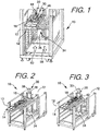
- FIGS. 1-3 show a hybrid cooled blade server enclosure 10 having a slot 12, or other type of support, in the enclosure for receiving and supporting a blade server 14.
- a single blade server 14 is shown for discussion purposes, but the enclosure can accommodate a plurality of blade servers supported by a plurality of slots 12 spaced from one another along a first direction and with each blade server extending in parallel planes.
- the plurality of slots 12 are shown oriented in vertical-spaced relationship as an example. However, it should be understood the plurality of slots 12 could also be oriented in horizontal-spaced relationship or even along other parallel planes.
- FIGS. 4 through 8 show the blade server 14 has a processor 16 that generates heat, and a heat transfer block 18 for dissipating heat from the processor 16. While a single heat exchange block 18 is shown, it is contemplated that numerous heat exchange blocks 18, say two to ten, for example, could be provided on each blade server without departing from the scope of the present invention.
- the heat exchange block should be fabricated from a material that dissipates heat such as a metal, including copper, aluminum, brass, iron, steel, etc.
- a surface 19 ( FIG. 5 ) of the heat exchange block 18 is adapted to contact a liquid-cooled surface described below. The surface can have a shape complementary to the shape of the cooled surface to maximize the area of engagement of these heat exchange surfaces to maximize the heat exchange capacity.
- Suitable shapes include those that are complementary to a portion of a circle, an ellipse, or a polygon.
- Suitable polygonal shapes include polygons having from 3 to 12 vertices and include, triangles, rectangles, squares, pentagons, etc.
- the heat exchange block can be configured to engage multiple chilled surfaces.
- the heat exchange block 18 can be mounted to the blade server directly or through rigid connections. It is also contemplated, the heat exchange block 18 can be mounted for pivotal movement about an axis and biased by a spring force so that the heat exchange block 18 is continuously pressed against the chilled surface 42.
- the surface of the heat exchange block can also be textured to form an irregular surface or a matte finish.
- the enclosure is said to be "hybrid cooled” as it provides a liquid chilled surface 42 in a position to contact the heat exchange (or transfer) block 18 of the blade server 14, in combination with, a flow of chilled air circulated by an electric fan.
- the heat transfer block 18 is dimensioned to contact the chilled surface 42 when the blade server is fully inserted into the enclosure. In this position, the heat transfer block 18 is in surface contact with the chilled surface 42 in a heat transfer zone 20 of the blade server.
- the heat transfer zone 20 encompasses a volume of space encompassing the processor 16, and moving rearward, to and including a fan area 72 of the enclosure, and any electrical components, heat fins or other features on the blade server.
- Such hybrid cooling provides a suitable environment for high speed and high heat generating processors used in some of today's blade servers.
- the chilled surface 42 is generally flat and rectangular, having top end and a bottom end and opposed lateral edges.
- the surface can be a continuous web of material having the chilled surface 42 on one side of the web, and an opposed surface on a second side of the web for directly or indirectly contacting a flow of chilled liquid from a source of chilled liquid.
- the chilled surface is on one face of a rectangular tube with chilled liquid flowing along its length through a lumen in the tube.
- a single chilled surface 42 can provide cooling to each and every blade server that can be accommodated in the enclosure or to a subset of the blades.
- the chilled surface 42 may also include a plurality of surfaces 42, one or more of each, corresponding to a possible location in the enclosure of a heat exchange block.
- a plurality of vertically spaced chilled surfaces 42 are provided in a manifold 30.
- One of each of the plurality of chilled surfaces 42 is positioned to engage a heat exchange block 18 of a blade server 14.
- the manifold 30 has a generally C-shaped wall 32 defining a vertical channel 34.
- the C-shaped wall has a generally rectangular backbone 36 with terminal flanges 38 extending perpendicularly away from the backbone 36 in the same direction.
- the terminal flanges 38 each have a plurality of vertically spaced through holes 40, one of each through hole 40 on one terminal flange 38 being in registration with one of each through hole 40 in the opposed terminal flange 38.
- a plurality of chilled fluid conduits 421 extends through the channel 34 from one terminal flange 38 to the opposed terminal flange 38 and at least one of each are for engaging the heat exchange block 18.
- Each of the plurality of fluid conduits 421 receives at one end 44 a supply of chilled liquid, and drains heated liquid from an opposed end 46 to remove heat from the heat exchange block 18.
- a chilled liquid supply conduit 48 extends vertically along one terminal flange 38 and has a lumen 49 for supplying chilled liquid under pressure to a plurality of branch supply conduits 50.
- the branch supply conduits 50 are vertically spaced from one another, and extend generally perpendicular from the chilled liquid supply conduit 48.
- One of each of the branch supply conduits 50 is in fluid communication with the end 44 of one of each of the fluid conduits 421.
- FIGS. 5 and 6 show a heated liquid drain conduit 52 extending vertically along the opposed terminal flange 38 and having a lumen 54 for draining heated liquid under pressure from a plurality of branch drain conduits 56.
- the branch drain conduits 56 are vertically spaced from one another, and extend perpendicular from the heated liquid drain conduit 54.
- One of each of the branch drain conduits 56 are in fluid communication with the end 46 of one of each of the fluid conduits 421.
- the flow of heated liquid is shown in FIG. 1 to be in a downward 58 direction while the flow of chilled liquid is shown flowing upward 60. This arrangement is merely an example and the direction of the flows of liquids can be different so long as the fluid flow serves to provide a chilled surface or chilled surfaces.
- the plurality of chilled fluid conduits 421 are positioned in the heat transfer zone 20.
- One of each of the plurality of chilled fluid conduits 421 engages a heat transfer block 18 of one of each of a plurality of blade servers 14 to provide liquid cooling to the enclosure 10.
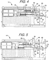
- the enclosure 10 also has an electric fan 70, or two fans as shown in FIGS. 4 and 5 mounted to the enclosure 10 for removing heat from the enclosure 10.
- FIGS. 1-3 show a fan area 72 with the fans 70 removed.
- the fan area 72 has fluid access through vents or an open wall to ambient conditions of a server room so that chilled air can be circulated in the heat exchange zone 20.
- the electric fan 70 is positioned outward of the enclosure 10 from the manifold 30, or conversely, the manifold 30 is positioned inward of the enclosure 10 from the fan 70 or fan area 72.
- Each of the chilled fluid conduits 421 has a generally circular shape in cross-sectional dimension, however, other cross-sectional shapes could be used such as oval or polygonal without departing from the scope of the present invention. Suitable polygonal shapes include polygons having from 3 to 12 vertices and include triangles, rectangles, squares, pentagons, etc. As shown in FIG. 7 , the heat transfer block 18 has a similar or complementary shaped channel 74, such as wave shaped as shown, or any shape complementary to the shapes of the chilled fluid conduits.
- valves and pumps to control the flow of chilled liquid from a source of chilled liquid to the chilled surfaces and for controlling the flow of heated liquid away from the chilled surface.
- valves could be used to individually and independently control the flow of chilled liquid so that only the chilled surfaces corresponding to an extant blade server are provided with cooling liquid.
- the idle chilled surfaces those with no corresponding blade server present, are not provided with a chilled liquid.
- the chilled liquid most preferably is liquid water but could also be other liquids, gases, supercritical fluids, including carbon dioxide (dry ice), and liquid nitrogen, for example.
- FIG. 6 shows an example of a blade server 14 having a processor 16.
- the blade server 14 has a plurality of heat exchange tubes 80.
- One set of tubes connects the processor 16 with the heat exchange block 18 and another set of tubes 80 connects the heat exchange block 18 with a set of heat fins 82.
Landscapes
- Engineering & Computer Science (AREA)
- Microelectronics & Electronic Packaging (AREA)
- Physics & Mathematics (AREA)
- Thermal Sciences (AREA)
- General Engineering & Computer Science (AREA)
- Computer Hardware Design (AREA)
- Theoretical Computer Science (AREA)
- Human Computer Interaction (AREA)
- General Physics & Mathematics (AREA)
- Power Engineering (AREA)
- Cooling Or The Like Of Electrical Apparatus (AREA)
Abstract
Description
- The present invention provides a hybrid cooled enclosure for a blade server having a high performance processor onboard.
- Enclosures for blade servers commonly accommodate a plurality of vertically spaced blade servers. The enclosures typically have a fan or a plurality of fans to remove heated air generated by a processor or processors onboard the blade. As processor speed increases, the required current to drive the processor increases as does the heat generated by the processor. Fans in some cases are inadequate and the temperature of the enclosure reaches a temperature where the processor can become damaged or be forced to operate at lower processing speeds to avoid damage. Thus, the need has arisen for additional cooling in blade server enclosures. The present invention provides an insert for mounting to a blade server enclosure to provide a liquid chilled surface, and preferably, a chilled surface dedicated to each blade server in the enclosure.
- The present invention provides a liquid-cooled insert for a blade server enclosure. The enclosure has a slot for receiving a blade server, the blade server having a processor that generates heat and a heat transfer block for dissipating heat from the processor. When the blade server is positioned in the enclosure the heat transfer block is located within a heat transfer zone of the enclosure. The insert includes a manifold mounted to the enclosure for supporting a chilled surface extending in a plane parallel to the slots and extending into the heat transfer zone. The chilled surface has a fluid conduit running there through with a cold liquid inlet and a hot liquid outlet. The chilled surface is in the heat transfer zone to engage the heat transfer block to dissipate heat from the processor when a blade server is within a slot of the enclosure. A first conduit connects a supply of cold liquid with the cold liquid inlet, and a second conduit connects the hot liquid outlet away from the heat transfer zone.
- The enclosure can have a first plurality of slots spaced from one another along a first direction and the manifold can have a second plurality of chilled surfaces spaced along the first direction wherein the second plurality is equal to or greater than the first plurality. The first conduit and the second conduit extend along the first direction, and the second plurality of chilled surfaces extends along a second direction generally perpendicular to the first direction. The chilled surface has a generally circular shape in cross-sectional dimension and the heat transfer block has a concave channel for contacting the chilled surface. The manifold has a peripheral wall defining a channel and the chilled surface is positioned within the channel.
- The present invention further provides a blade server enclosure having a slot in the enclosure for receiving a blade server having a processor that generates heat, and a heat transfer block for dissipating heat from the processor in a heat transfer zone of the enclosure. A manifold is mounted to the enclosure for supporting a chilled surface extending in a plane parallel to the slot and extending into the heat transfer zone. The chilled surface has a fluid conduit running there through and having a cold liquid inlet and a hot liquid outlet, the chilled surface is in the heat transfer zone to engage a heat transfer block. The enclosure further has a first conduit connecting a supply of cold liquid with the cold liquid inlet; and a second conduit connecting the hot liquid outlet away from the heat transfer zone.
- The blade server enclosure further includes an electric fan mounted to the enclosure for dissipating heat from the enclosure. The manifold is positioned inward of the enclosure with respect to the fan. The enclosure has a first plurality of slots spaced from one another along a first direction, and the manifold has a second plurality of chilled surfaces spaced along the first direction wherein the second plurality is equal to or greater than the first plurality. The first conduit and the second conduit extend along the first direction, and the second plurality of chilled surfaces extends along a second direction generally perpendicular to the first direction. The chilled surface has a generally circular shape in cross sectional dimension and the heat transfer block has a concave channel for contacting the chilled surface. The manifold has a peripheral wall defining a channel and the chilled surface is positioned within the channel.
- The present invention further provides a hybrid cooled blade server enclosure having a slot in the enclosure for receiving a blade server having a processor that generates heat, and a heat transfer block for dissipating heat from the processor in a heat transfer zone of the enclosure. A manifold is mounted to the enclosure for supporting a chilled surface extending in a plane parallel to the slot and extending into the heat transfer zone. The chilled surface has a fluid conduit running there through having a cold liquid inlet and a hot liquid outlet. The chilled surface is in the heat transfer zone to engage a heat transfer block. A first conduit connects a supply of cold liquid with the cold liquid inlet, and a second conduit connects the hot liquid outlet to a position outside the heat transfer zone. The enclosure also has an electric fan mounted to the enclosure for removing heat from the enclosure. The electric fan is positioned outward of the enclosure from the manifold.
- The hybrid cooled blade server enclosure further includes a first plurality of slots spaced from another along a first direction in the enclosure and the manifold having a second plurality of chilled surfaces spaced along the first distance wherein the second plurality is equal to or greater than the first plurality. The first conduit and the second conduit extend along the first direction, and the second plurality of chilled surfaces extend along a second direction generally perpendicular to the first direction. The chilled surface has a generally circular shape in cross sectional dimension and the heat transfer block has a concave channel for contacting the chilled surface. The manifold has a peripheral wall defining a channel and the chilled surface is positioned within the channel and the peripheral wall is generally C-shaped. The cold liquid inlet extends through a hole in the peripheral wall.
- To understand the present invention, it will now be described by way of example, with reference to the accompanying drawings and attachments in which:
-
FIG. 1 is a perspective view of a water-cooled blade server enclosure. -
FIG. 2 is a perspective view of a water-cooled blade server enclosure during insertion of a blade server into the enclosure. -
FIG. 3 is a perspective view of a water-cooled blade server enclosure with the blade server fully inserted into the enclosure with a heat exchange block of the blade server in contact with a chilled surface of an insert. -
FIG. 4 is a top plan view of a blade server with its heat exchange block in contact with the chilled surface of the insert. -
FIG. 5 is a top plan view of a blade server with its heat exchange block separated from the chilled surface of the insert. -
FIG. 6 is a perspective view of a blade server. -
FIG. 7 is an enlarged view of a heat transfer zone of the enclosure. -
FIG. 8 is an enlarged view in partial cross section taken along line 8-8 ofFIG. 4 . - While this invention is susceptible of embodiments in many different forms, there is shown in the drawings and will herein be described in detail preferred embodiments of the invention with the understanding that the present disclosure is to be considered as an exemplification of the principles of the invention and is not intended to limit the broad aspect of the invention to the embodiments illustrated.
-
FIGS. 1-3 show a hybrid cooledblade server enclosure 10 having aslot 12, or other type of support, in the enclosure for receiving and supporting ablade server 14. Asingle blade server 14 is shown for discussion purposes, but the enclosure can accommodate a plurality of blade servers supported by a plurality ofslots 12 spaced from one another along a first direction and with each blade server extending in parallel planes. The plurality ofslots 12 are shown oriented in vertical-spaced relationship as an example. However, it should be understood the plurality ofslots 12 could also be oriented in horizontal-spaced relationship or even along other parallel planes. -
FIGS. 4 through 8 show theblade server 14 has aprocessor 16 that generates heat, and aheat transfer block 18 for dissipating heat from theprocessor 16. While a singleheat exchange block 18 is shown, it is contemplated that numerousheat exchange blocks 18, say two to ten, for example, could be provided on each blade server without departing from the scope of the present invention. The heat exchange block should be fabricated from a material that dissipates heat such as a metal, including copper, aluminum, brass, iron, steel, etc. A surface 19 (FIG. 5 ) of theheat exchange block 18 is adapted to contact a liquid-cooled surface described below. The surface can have a shape complementary to the shape of the cooled surface to maximize the area of engagement of these heat exchange surfaces to maximize the heat exchange capacity. Suitable shapes include those that are complementary to a portion of a circle, an ellipse, or a polygon. Suitable polygonal shapes include polygons having from 3 to 12 vertices and include, triangles, rectangles, squares, pentagons, etc. Additionally, the heat exchange block can be configured to engage multiple chilled surfaces. - The
heat exchange block 18 can be mounted to the blade server directly or through rigid connections. It is also contemplated, theheat exchange block 18 can be mounted for pivotal movement about an axis and biased by a spring force so that theheat exchange block 18 is continuously pressed against thechilled surface 42. The surface of the heat exchange block can also be textured to form an irregular surface or a matte finish. - The enclosure is said to be "hybrid cooled" as it provides a liquid
chilled surface 42 in a position to contact the heat exchange (or transfer) block 18 of theblade server 14, in combination with, a flow of chilled air circulated by an electric fan. Theheat transfer block 18 is dimensioned to contact thechilled surface 42 when the blade server is fully inserted into the enclosure. In this position, theheat transfer block 18 is in surface contact with thechilled surface 42 in aheat transfer zone 20 of the blade server. Theheat transfer zone 20 encompasses a volume of space encompassing theprocessor 16, and moving rearward, to and including afan area 72 of the enclosure, and any electrical components, heat fins or other features on the blade server. Such hybrid cooling provides a suitable environment for high speed and high heat generating processors used in some of today's blade servers. - In one form of the invention, the
chilled surface 42 is generally flat and rectangular, having top end and a bottom end and opposed lateral edges. The surface can be a continuous web of material having the chilledsurface 42 on one side of the web, and an opposed surface on a second side of the web for directly or indirectly contacting a flow of chilled liquid from a source of chilled liquid. In one form of the invention, the chilled surface is on one face of a rectangular tube with chilled liquid flowing along its length through a lumen in the tube. A single chilledsurface 42 can provide cooling to each and every blade server that can be accommodated in the enclosure or to a subset of the blades. - The
chilled surface 42 may also include a plurality ofsurfaces 42, one or more of each, corresponding to a possible location in the enclosure of a heat exchange block. An enclosure that can accommodate, say five blade servers, will have 5 chilled surfaces. There may be more than one chilled surface per blade including multiples thereof such as two to five chilled surfaces per blade. It is also contemplated that a single chilled surface can contact more than one heat exchange block. - As best seen in
FIGS. 1-3 and7 , a plurality of vertically spacedchilled surfaces 42 are provided in amanifold 30. One of each of the plurality ofchilled surfaces 42 is positioned to engage aheat exchange block 18 of ablade server 14. The manifold 30 has a generally C-shapedwall 32 defining avertical channel 34. The C-shaped wall has a generallyrectangular backbone 36 withterminal flanges 38 extending perpendicularly away from thebackbone 36 in the same direction. Theterminal flanges 38 each have a plurality of vertically spaced throughholes 40, one of each throughhole 40 on oneterminal flange 38 being in registration with one of each throughhole 40 in the opposedterminal flange 38. A plurality of chilled fluid conduits 421 extends through thechannel 34 from oneterminal flange 38 to the opposedterminal flange 38 and at least one of each are for engaging theheat exchange block 18. Each of the plurality of fluid conduits 421 receives at one end 44 a supply of chilled liquid, and drains heated liquid from anopposed end 46 to remove heat from theheat exchange block 18. - A chilled
liquid supply conduit 48 extends vertically along oneterminal flange 38 and has alumen 49 for supplying chilled liquid under pressure to a plurality ofbranch supply conduits 50. (FIGS. 5 and6 ) Thebranch supply conduits 50 are vertically spaced from one another, and extend generally perpendicular from the chilledliquid supply conduit 48. One of each of thebranch supply conduits 50 is in fluid communication with theend 44 of one of each of the fluid conduits 421. -
FIGS. 5 and6 show a heatedliquid drain conduit 52 extending vertically along the opposedterminal flange 38 and having alumen 54 for draining heated liquid under pressure from a plurality ofbranch drain conduits 56. Thebranch drain conduits 56 are vertically spaced from one another, and extend perpendicular from the heatedliquid drain conduit 54. One of each of thebranch drain conduits 56 are in fluid communication with theend 46 of one of each of the fluid conduits 421. The flow of heated liquid is shown inFIG. 1 to be in a downward 58 direction while the flow of chilled liquid is shown flowing upward 60. This arrangement is merely an example and the direction of the flows of liquids can be different so long as the fluid flow serves to provide a chilled surface or chilled surfaces. - The plurality of chilled fluid conduits 421 are positioned in the
heat transfer zone 20. One of each of the plurality of chilled fluid conduits 421 engages aheat transfer block 18 of one of each of a plurality ofblade servers 14 to provide liquid cooling to theenclosure 10. Theenclosure 10 also has anelectric fan 70, or two fans as shown inFIGS. 4 and 5 mounted to theenclosure 10 for removing heat from theenclosure 10.FIGS. 1-3 show afan area 72 with thefans 70 removed. Thefan area 72 has fluid access through vents or an open wall to ambient conditions of a server room so that chilled air can be circulated in theheat exchange zone 20. Theelectric fan 70 is positioned outward of theenclosure 10 from the manifold 30, or conversely, the manifold 30 is positioned inward of theenclosure 10 from thefan 70 orfan area 72. - Each of the chilled fluid conduits 421 has a generally circular shape in cross-sectional dimension, however, other cross-sectional shapes could be used such as oval or polygonal without departing from the scope of the present invention. Suitable polygonal shapes include polygons having from 3 to 12 vertices and include triangles, rectangles, squares, pentagons, etc. As shown in
FIG. 7 , theheat transfer block 18 has a similar or complementary shapedchannel 74, such as wave shaped as shown, or any shape complementary to the shapes of the chilled fluid conduits. - It is contemplated providing valves and pumps to control the flow of chilled liquid from a source of chilled liquid to the chilled surfaces and for controlling the flow of heated liquid away from the chilled surface. For example, valves could be used to individually and independently control the flow of chilled liquid so that only the chilled surfaces corresponding to an extant blade server are provided with cooling liquid. The idle chilled surfaces, those with no corresponding blade server present, are not provided with a chilled liquid. The chilled liquid most preferably is liquid water but could also be other liquids, gases, supercritical fluids, including carbon dioxide (dry ice), and liquid nitrogen, for example.
-
FIG. 6 shows an example of ablade server 14 having aprocessor 16. Theblade server 14 has a plurality ofheat exchange tubes 80. One set of tubes connects theprocessor 16 with theheat exchange block 18 and another set oftubes 80 connects theheat exchange block 18 with a set ofheat fins 82. - While various embodiments of the present invention have been described above, it should be understood that they have been presented by way of example only, and not limitation. Numerous changes to the disclosed embodiments can be made in accordance with the disclosure herein without departing from the spirit or scope of the invention. Thus, the breadth and scope of the present invention should not be limited by any of the above described embodiments. Rather, the scope of the invention should be defined in accordance with the following claims and their equivalents.
- Although the invention has been illustrated and described with respect to one or more implementations, equivalent alterations and modifications will occur to others skilled in the art upon the reading and understanding of this specification and the annexed drawings. In addition, while a particular feature of the invention may have been disclosed with respect to only one of several implementations, such feature may be combined with one or more other features of the other implementations as may be desired and advantageous for any given or particular application.
- The terminology used herein is for the purpose of describing particular embodiments only and is not intended to be limiting of the invention. As used herein, the singular forms "a", "an" and "the" are intended to include the plural forms as well, unless the context clearly indicates otherwise. Furthermore, to the extent that the terms "including", "includes", "having", "has", "with", or variants thereof are used in either the detailed description and/or the claims, such terms are intended to be inclusive in a manner similar to the term "comprising."
- Unless otherwise defined, all terms (including technical and scientific terms) used herein have the same meaning as commonly understood by one of ordinary skill in the art to which this invention belongs. It will be further understood that terms, such as those defined in commonly used dictionaries, should be interpreted as having a meaning that is consistent with their meaning in the context of the relevant art and will not be interpreted in an idealized or overly formal sense unless expressly so defined herein.
Claims (15)
- A liquid-cooled insert for a blade server enclosure, the blade server enclosure having a slot (12) for receiving a blade server (14), the blade server (14) having a processor (16) that generates heat and a heat transfer block (18) for dissipating heat from the processor (16), when the blade server (14) is positioned in the blade server enclosure, the heat transfer block (18) is located within a heat transfer zone (20) of the blade server enclosure, the insert comprising:a manifold (30) mounted to the blade server enclosure for supporting a chilled surface (42) extending into the heat transfer zone (20), the chilled surface (42) having a fluid conduit (421) running therethrough having a cold liquid inlet and a hot liquid outlet, the chilled surface (42) is in the heat transfer zone (20) and is in surface contact with the heat transfer block (18);a first conduit (48) connecting a supply of cold liquid with the cold liquid inlet; anda second conduit (52) connecting the hot liquid outlet to a location away from the heat transfer zone (20).
- The liquid-cooled insert of claim 1, further comprising a first plurality of slots (12) spaced from one another along a first direction in the blade server enclosure and the manifold (30) having a second plurality of chilled surfaces (42) spaced along the first direction, wherein the second plurality is equal to or greater than the first plurality.
- The liquid-cooled insert of claim 2, wherein the first conduit (48) and the second conduit (52) extend along the first direction, and the second plurality of chilled surfaces (42) extend along a second direction substantially perpendicular to the first direction.
- The liquid-cooled insert of any one of proceeding claims, wherein the chilled surface (42) has a substantially circular shape in cross-sectional dimension and the heat transfer block (18) has a concave channel (74) for contacting the chilled surface (42).
- The liquid-cooled insert of any one of proceeding claims, wherein the manifold (30) has a peripheral wall (32) defining a channel (34) and the chilled surface (42) is positioned within the channel (34).
- A blade server enclosure, comprising:a slot (12) in the blade server enclosure for receiving a blade server (14) having a processor (16) that generates heat, and a heat transfer block (18) for dissipating heat from the processor (16) in a heat transfer zone (20) of the blade server enclosure;a manifold (30) mounted to the blade server enclosure for supporting a chilled surface (42) extending into the heat transfer zone (20), the chilled surface (42) having a fluid conduit (421) running therethrough having a cold liquid inlet and a hot liquid outlet, the chilled surface (42) is in surface contact with the heat transfer block (18);a first conduit (48) connecting a supply of cold liquid with the cold liquid inlet; anda second conduit (52) connecting the hot liquid outlet away from the heat transfer zone (20).
- The blade server enclosure of claim 6, further comprising an electric fan (70) mounted to the blade server enclosure for dissipating heat from the blade server enclosure.
- The blade server enclosure of claim 7, wherein the manifold (30) is positioned inward of the enclosure with respect to the fan (70).
- A hybrid cooled blade server enclosure (10), comprising:a slot (12) in the hybrid cooled blade server enclosure (10) for receiving a blade server (14) having a processor (16) that generates heat, and a heat transfer block (18) for dissipating heat from the processor (16) in a heat transfer zone (20) of the hybrid cooled blade server enclosure (10);a manifold (30) mounted to the hybrid cooled blade server enclosure (10) for supporting a chilled surface (42) extending into the heat transfer zone (20), the chilled surface (42) having a fluid conduit (421) running there through having a cold liquid inlet and a hot liquid outlet, the chilled surface (42) is in surface contact with the heat transfer block (18);a first conduit (48) connecting a supply of cold liquid with the cold liquid inlet;a second conduit (52) connecting the hot liquid outlet away from the heat transfer zone (20); andan electric fan (70) mounted to the hybrid cooled blade server enclosure (10) for removing heat from the hybrid cooled blade server enclosure (10).
- The hybrid cooled blade server enclosure (10) of claim 9, wherein the electric fan (70) is positioned outward of the hybrid cooled blade server enclosure (10) from the manifold (30).
- The hybrid cooled blade server enclosure (10) of claim 9 or 10, further comprising a first plurality of slots (12) spaced from another along a first direction in the hybrid cooled blade server enclosure (10) and the manifold (30) having a second plurality of chilled surfaces (42) spaced along a first distance, wherein the second plurality is equal to or greater than the first plurality.
- The hybrid cooled blade server enclosure (10) of claim 11, wherein the first conduit (48) and the second conduit (52) extend along the first direction and the second plurality of chilled surfaces (42) extend along a second direction substantially perpendicular to the first direction.
- The hybrid cooled blade server enclosure (10) of any one of claims 9 to 12, wherein the chilled surface (42) has a substantially circular shape in cross sectional dimension and the heat transfer block (18) has a concave channel (74) for contacting the chilled surface (42).
- The hybrid cooled blade server enclosure (10) of any one of claims 9 to 13, wherein the manifold (30) has a peripheral wall (32) defining a channel (34) and the chilled surface (42) is positioned within the channel (34).
- The hybrid cooled blade server enclosure (10) of claim 14, wherein the cold liquid inlet extends through a hole in the peripheral wall (32).
Applications Claiming Priority (1)
| Application Number | Priority Date | Filing Date | Title |
|---|---|---|---|
| US15/581,491 US10045466B1 (en) | 2017-04-28 | 2017-04-28 | High performance server through improved hybrid cooling |
Publications (2)
| Publication Number | Publication Date |
|---|---|
| EP3397037A1 true EP3397037A1 (en) | 2018-10-31 |
| EP3397037B1 EP3397037B1 (en) | 2021-05-19 |
Family
ID=60119847
Family Applications (1)
| Application Number | Title | Priority Date | Filing Date |
|---|---|---|---|
| EP17195881.2A Active EP3397037B1 (en) | 2017-04-28 | 2017-10-11 | High performance server through improved hybrid cooling |
Country Status (5)
| Country | Link |
|---|---|
| US (1) | US10045466B1 (en) |
| EP (1) | EP3397037B1 (en) |
| JP (1) | JP6496795B2 (en) |
| CN (1) | CN108803835B (en) |
| TW (1) | TWI635796B (en) |
Cited By (1)
| Publication number | Priority date | Publication date | Assignee | Title |
|---|---|---|---|---|
| WO2023232323A1 (en) * | 2022-05-31 | 2023-12-07 | Robert Bosch Gmbh | Device comprising at least one exchangeable electronics assembly of a motor vehicle |
Families Citing this family (6)
| Publication number | Priority date | Publication date | Assignee | Title |
|---|---|---|---|---|
| TWI678494B (en) * | 2018-11-19 | 2019-12-01 | 廣運機械工程股份有限公司 | Branching device for blind water insertion |
| DK3829278T3 (en) | 2019-11-29 | 2022-06-20 | Ovh | COOLING DEVICE FOR A SERVER WHICH CAN BE MOUNTED IN A SERVER RACK |
| CN112965581A (en) * | 2021-03-08 | 2021-06-15 | 山东商智伙伴网络科技有限公司 | Server stability auxiliary device for software back-end big data operation |
| CN113163683B (en) * | 2021-04-02 | 2023-05-30 | 西安易朴通讯技术有限公司 | Liquid cooling heat dissipation equipment, cabinet and system |
| US12108568B2 (en) | 2021-11-12 | 2024-10-01 | Microsoft Technology Licensing, Llc | Systems and methods for thermal management of high-capacity devices in immersion-cooled datacenters |
| US12108572B2 (en) | 2022-03-31 | 2024-10-01 | Microsoft Technology Licensing, Llc | Folded graphite fins for heatsinks |
Citations (2)
| Publication number | Priority date | Publication date | Assignee | Title |
|---|---|---|---|---|
| US20130271918A1 (en) * | 2012-04-16 | 2013-10-17 | John Philip Neville Hughes | Cold plate with reduced bubble effects |
| US20150160702A1 (en) * | 2013-12-10 | 2015-06-11 | Silicon Graphics International Corp. | Hot Swappable Computer Cooling System |
Family Cites Families (11)
| Publication number | Priority date | Publication date | Assignee | Title |
|---|---|---|---|---|
| US20040008483A1 (en) * | 2002-07-13 | 2004-01-15 | Kioan Cheon | Water cooling type cooling system for electronic device |
| JP2004363308A (en) * | 2003-06-04 | 2004-12-24 | Hitachi Ltd | Rack mount server system |
| CN2641703Y (en) * | 2003-06-30 | 2004-09-15 | 悦舍科技股份有限公司 | Liquid Cooling Module for Servers |
| US7012807B2 (en) * | 2003-09-30 | 2006-03-14 | International Business Machines Corporation | Thermal dissipation assembly and fabrication method for electronics drawer of a multiple-drawer electronics rack |
| TWM271199U (en) | 2004-12-31 | 2005-07-21 | Inventec Corp | Heat dissipation system for blade server |
| US7423870B2 (en) * | 2005-11-18 | 2008-09-09 | International Business Machines Corporation | Blade server assembly |
| JP2010114121A (en) * | 2008-11-04 | 2010-05-20 | Daikin Ind Ltd | Heat radiator of electrical component |
| CN101859738B (en) * | 2009-04-07 | 2011-12-07 | 康舒科技股份有限公司 | Large-area liquid-cooled heat dissipation device |
| WO2011040129A1 (en) * | 2009-09-29 | 2011-04-07 | 日本電気株式会社 | Heat conveying structure for electronic device |
| US9560794B2 (en) * | 2011-11-08 | 2017-01-31 | Panasonic Intellectual Property Management Co., Ltd. | Cooling device for cooling rack-type server, and data center provided with same |
| US20160353613A1 (en) | 2015-05-27 | 2016-12-01 | Quanta Computer Inc. | Hybrid cooling for computer systems |
-
2017
- 2017-04-28 US US15/581,491 patent/US10045466B1/en active Active
- 2017-06-27 TW TW106121490A patent/TWI635796B/en active
- 2017-07-14 CN CN201710573656.6A patent/CN108803835B/en active Active
- 2017-10-04 JP JP2017194364A patent/JP6496795B2/en active Active
- 2017-10-11 EP EP17195881.2A patent/EP3397037B1/en active Active
Patent Citations (2)
| Publication number | Priority date | Publication date | Assignee | Title |
|---|---|---|---|---|
| US20130271918A1 (en) * | 2012-04-16 | 2013-10-17 | John Philip Neville Hughes | Cold plate with reduced bubble effects |
| US20150160702A1 (en) * | 2013-12-10 | 2015-06-11 | Silicon Graphics International Corp. | Hot Swappable Computer Cooling System |
Cited By (1)
| Publication number | Priority date | Publication date | Assignee | Title |
|---|---|---|---|---|
| WO2023232323A1 (en) * | 2022-05-31 | 2023-12-07 | Robert Bosch Gmbh | Device comprising at least one exchangeable electronics assembly of a motor vehicle |
Also Published As
| Publication number | Publication date |
|---|---|
| CN108803835B (en) | 2020-07-24 |
| EP3397037B1 (en) | 2021-05-19 |
| TWI635796B (en) | 2018-09-11 |
| TW201840269A (en) | 2018-11-01 |
| JP6496795B2 (en) | 2019-04-10 |
| JP2018190373A (en) | 2018-11-29 |
| CN108803835A (en) | 2018-11-13 |
| US10045466B1 (en) | 2018-08-07 |
Similar Documents
| Publication | Publication Date | Title |
|---|---|---|
| US10045466B1 (en) | High performance server through improved hybrid cooling | |
| US11930618B2 (en) | Liquid cooling head and liquid cooling device with the same | |
| CN204836927U (en) | Liquid-cooled radiator and its cooling system | |
| ES2872875T3 (en) | Liquid cooling systems for heat generating devices | |
| TWI796860B (en) | Liquid cooling pumping unit | |
| US7128140B2 (en) | Heat sinks | |
| JP2019537152A (en) | Fluid cooling system | |
| CN211019743U (en) | Cooling unit | |
| US10921067B2 (en) | Water-cooling radiator structure with internal partition member | |
| US20140321050A1 (en) | Cooling device for cooling rack-type server, and data center provided with same | |
| JP2019216192A (en) | Electronic apparatus | |
| US11236738B2 (en) | Cooling apparatus | |
| CN211019741U (en) | Cooling device | |
| TWM511069U (en) | Liquid cooled heat sink and its heat dissipation system | |
| JP7238400B2 (en) | Cooling system | |
| US20210282298A1 (en) | Cooling device | |
| CN110529951B (en) | Evaporation type water-cooling fan water distribution system | |
| US20140150999A1 (en) | Container data center with cooling system | |
| JP6081186B2 (en) | Liquid cooling device | |
| CN215524295U (en) | Telescopic condenser | |
| CN221476091U (en) | Quick cooling device of line is moulded to stone | |
| CN106524805A (en) | Conformal vertical heat transfer surface heat pipe radiator | |
| CN222865111U (en) | A kind of temperature conductor and neck hanging air conditioner | |
| US12408295B2 (en) | Fluid distribution assembly and cooling system including the same | |
| CN216352188U (en) | Novel notebook cooling system |
Legal Events
| Date | Code | Title | Description |
|---|---|---|---|
| PUAI | Public reference made under article 153(3) epc to a published international application that has entered the european phase |
Free format text: ORIGINAL CODE: 0009012 |
|
| STAA | Information on the status of an ep patent application or granted ep patent |
Free format text: STATUS: REQUEST FOR EXAMINATION WAS MADE |
|
| 17P | Request for examination filed |
Effective date: 20180813 |
|
| AK | Designated contracting states |
Kind code of ref document: A1 Designated state(s): AL AT BE BG CH CY CZ DE DK EE ES FI FR GB GR HR HU IE IS IT LI LT LU LV MC MK MT NL NO PL PT RO RS SE SI SK SM TR |
|
| AX | Request for extension of the european patent |
Extension state: BA ME |
|
| GRAP | Despatch of communication of intention to grant a patent |
Free format text: ORIGINAL CODE: EPIDOSNIGR1 |
|
| STAA | Information on the status of an ep patent application or granted ep patent |
Free format text: STATUS: GRANT OF PATENT IS INTENDED |
|
| INTG | Intention to grant announced |
Effective date: 20201211 |
|
| GRAS | Grant fee paid |
Free format text: ORIGINAL CODE: EPIDOSNIGR3 |
|
| GRAA | (expected) grant |
Free format text: ORIGINAL CODE: 0009210 |
|
| STAA | Information on the status of an ep patent application or granted ep patent |
Free format text: STATUS: THE PATENT HAS BEEN GRANTED |
|
| AK | Designated contracting states |
Kind code of ref document: B1 Designated state(s): AL AT BE BG CH CY CZ DE DK EE ES FI FR GB GR HR HU IE IS IT LI LT LU LV MC MK MT NL NO PL PT RO RS SE SI SK SM TR |
|
| REG | Reference to a national code |
Ref country code: GB Ref legal event code: FG4D |
|
| REG | Reference to a national code |
Ref country code: CH Ref legal event code: EP |
|
| REG | Reference to a national code |
Ref country code: DE Ref legal event code: R096 Ref document number: 602017038746 Country of ref document: DE |
|
| REG | Reference to a national code |
Ref country code: AT Ref legal event code: REF Ref document number: 1395272 Country of ref document: AT Kind code of ref document: T Effective date: 20210615 |
|
| REG | Reference to a national code |
Ref country code: IE Ref legal event code: FG4D |
|
| REG | Reference to a national code |
Ref country code: LT Ref legal event code: MG9D |
|
| REG | Reference to a national code |
Ref country code: AT Ref legal event code: MK05 Ref document number: 1395272 Country of ref document: AT Kind code of ref document: T Effective date: 20210519 |
|
| REG | Reference to a national code |
Ref country code: NL Ref legal event code: MP Effective date: 20210519 |
|
| PG25 | Lapsed in a contracting state [announced via postgrant information from national office to epo] |
Ref country code: BG Free format text: LAPSE BECAUSE OF FAILURE TO SUBMIT A TRANSLATION OF THE DESCRIPTION OR TO PAY THE FEE WITHIN THE PRESCRIBED TIME-LIMIT Effective date: 20210819 Ref country code: AT Free format text: LAPSE BECAUSE OF FAILURE TO SUBMIT A TRANSLATION OF THE DESCRIPTION OR TO PAY THE FEE WITHIN THE PRESCRIBED TIME-LIMIT Effective date: 20210519 Ref country code: HR Free format text: LAPSE BECAUSE OF FAILURE TO SUBMIT A TRANSLATION OF THE DESCRIPTION OR TO PAY THE FEE WITHIN THE PRESCRIBED TIME-LIMIT Effective date: 20210519 Ref country code: LT Free format text: LAPSE BECAUSE OF FAILURE TO SUBMIT A TRANSLATION OF THE DESCRIPTION OR TO PAY THE FEE WITHIN THE PRESCRIBED TIME-LIMIT Effective date: 20210519 Ref country code: FI Free format text: LAPSE BECAUSE OF FAILURE TO SUBMIT A TRANSLATION OF THE DESCRIPTION OR TO PAY THE FEE WITHIN THE PRESCRIBED TIME-LIMIT Effective date: 20210519 |
|
| PG25 | Lapsed in a contracting state [announced via postgrant information from national office to epo] |
Ref country code: IS Free format text: LAPSE BECAUSE OF FAILURE TO SUBMIT A TRANSLATION OF THE DESCRIPTION OR TO PAY THE FEE WITHIN THE PRESCRIBED TIME-LIMIT Effective date: 20210919 Ref country code: GR Free format text: LAPSE BECAUSE OF FAILURE TO SUBMIT A TRANSLATION OF THE DESCRIPTION OR TO PAY THE FEE WITHIN THE PRESCRIBED TIME-LIMIT Effective date: 20210820 Ref country code: LV Free format text: LAPSE BECAUSE OF FAILURE TO SUBMIT A TRANSLATION OF THE DESCRIPTION OR TO PAY THE FEE WITHIN THE PRESCRIBED TIME-LIMIT Effective date: 20210519 Ref country code: SE Free format text: LAPSE BECAUSE OF FAILURE TO SUBMIT A TRANSLATION OF THE DESCRIPTION OR TO PAY THE FEE WITHIN THE PRESCRIBED TIME-LIMIT Effective date: 20210519 Ref country code: RS Free format text: LAPSE BECAUSE OF FAILURE TO SUBMIT A TRANSLATION OF THE DESCRIPTION OR TO PAY THE FEE WITHIN THE PRESCRIBED TIME-LIMIT Effective date: 20210519 Ref country code: PT Free format text: LAPSE BECAUSE OF FAILURE TO SUBMIT A TRANSLATION OF THE DESCRIPTION OR TO PAY THE FEE WITHIN THE PRESCRIBED TIME-LIMIT Effective date: 20210920 Ref country code: PL Free format text: LAPSE BECAUSE OF FAILURE TO SUBMIT A TRANSLATION OF THE DESCRIPTION OR TO PAY THE FEE WITHIN THE PRESCRIBED TIME-LIMIT Effective date: 20210519 Ref country code: NO Free format text: LAPSE BECAUSE OF FAILURE TO SUBMIT A TRANSLATION OF THE DESCRIPTION OR TO PAY THE FEE WITHIN THE PRESCRIBED TIME-LIMIT Effective date: 20210819 |
|
| PG25 | Lapsed in a contracting state [announced via postgrant information from national office to epo] |
Ref country code: NL Free format text: LAPSE BECAUSE OF FAILURE TO SUBMIT A TRANSLATION OF THE DESCRIPTION OR TO PAY THE FEE WITHIN THE PRESCRIBED TIME-LIMIT Effective date: 20210519 |
|
| PG25 | Lapsed in a contracting state [announced via postgrant information from national office to epo] |
Ref country code: SK Free format text: LAPSE BECAUSE OF FAILURE TO SUBMIT A TRANSLATION OF THE DESCRIPTION OR TO PAY THE FEE WITHIN THE PRESCRIBED TIME-LIMIT Effective date: 20210519 Ref country code: SM Free format text: LAPSE BECAUSE OF FAILURE TO SUBMIT A TRANSLATION OF THE DESCRIPTION OR TO PAY THE FEE WITHIN THE PRESCRIBED TIME-LIMIT Effective date: 20210519 Ref country code: DK Free format text: LAPSE BECAUSE OF FAILURE TO SUBMIT A TRANSLATION OF THE DESCRIPTION OR TO PAY THE FEE WITHIN THE PRESCRIBED TIME-LIMIT Effective date: 20210519 Ref country code: CZ Free format text: LAPSE BECAUSE OF FAILURE TO SUBMIT A TRANSLATION OF THE DESCRIPTION OR TO PAY THE FEE WITHIN THE PRESCRIBED TIME-LIMIT Effective date: 20210519 Ref country code: EE Free format text: LAPSE BECAUSE OF FAILURE TO SUBMIT A TRANSLATION OF THE DESCRIPTION OR TO PAY THE FEE WITHIN THE PRESCRIBED TIME-LIMIT Effective date: 20210519 Ref country code: RO Free format text: LAPSE BECAUSE OF FAILURE TO SUBMIT A TRANSLATION OF THE DESCRIPTION OR TO PAY THE FEE WITHIN THE PRESCRIBED TIME-LIMIT Effective date: 20210519 Ref country code: ES Free format text: LAPSE BECAUSE OF FAILURE TO SUBMIT A TRANSLATION OF THE DESCRIPTION OR TO PAY THE FEE WITHIN THE PRESCRIBED TIME-LIMIT Effective date: 20210519 |
|
| REG | Reference to a national code |
Ref country code: DE Ref legal event code: R097 Ref document number: 602017038746 Country of ref document: DE |
|
| PLBE | No opposition filed within time limit |
Free format text: ORIGINAL CODE: 0009261 |
|
| STAA | Information on the status of an ep patent application or granted ep patent |
Free format text: STATUS: NO OPPOSITION FILED WITHIN TIME LIMIT |
|
| 26N | No opposition filed |
Effective date: 20220222 |
|
| REG | Reference to a national code |
Ref country code: CH Ref legal event code: PL |
|
| PG25 | Lapsed in a contracting state [announced via postgrant information from national office to epo] |
Ref country code: IS Free format text: LAPSE BECAUSE OF FAILURE TO SUBMIT A TRANSLATION OF THE DESCRIPTION OR TO PAY THE FEE WITHIN THE PRESCRIBED TIME-LIMIT Effective date: 20210919 Ref country code: AL Free format text: LAPSE BECAUSE OF FAILURE TO SUBMIT A TRANSLATION OF THE DESCRIPTION OR TO PAY THE FEE WITHIN THE PRESCRIBED TIME-LIMIT Effective date: 20210519 |
|
| REG | Reference to a national code |
Ref country code: BE Ref legal event code: MM Effective date: 20211031 |
|
| PG25 | Lapsed in a contracting state [announced via postgrant information from national office to epo] |
Ref country code: MC Free format text: LAPSE BECAUSE OF FAILURE TO SUBMIT A TRANSLATION OF THE DESCRIPTION OR TO PAY THE FEE WITHIN THE PRESCRIBED TIME-LIMIT Effective date: 20210519 |
|
| PG25 | Lapsed in a contracting state [announced via postgrant information from national office to epo] |
Ref country code: LU Free format text: LAPSE BECAUSE OF NON-PAYMENT OF DUE FEES Effective date: 20211011 Ref country code: IT Free format text: LAPSE BECAUSE OF FAILURE TO SUBMIT A TRANSLATION OF THE DESCRIPTION OR TO PAY THE FEE WITHIN THE PRESCRIBED TIME-LIMIT Effective date: 20210519 Ref country code: BE Free format text: LAPSE BECAUSE OF NON-PAYMENT OF DUE FEES Effective date: 20211031 |
|
| PG25 | Lapsed in a contracting state [announced via postgrant information from national office to epo] |
Ref country code: LI Free format text: LAPSE BECAUSE OF NON-PAYMENT OF DUE FEES Effective date: 20211031 Ref country code: CH Free format text: LAPSE BECAUSE OF NON-PAYMENT OF DUE FEES Effective date: 20211031 |
|
| PG25 | Lapsed in a contracting state [announced via postgrant information from national office to epo] |
Ref country code: IE Free format text: LAPSE BECAUSE OF NON-PAYMENT OF DUE FEES Effective date: 20211011 |
|
| PG25 | Lapsed in a contracting state [announced via postgrant information from national office to epo] |
Ref country code: CY Free format text: LAPSE BECAUSE OF FAILURE TO SUBMIT A TRANSLATION OF THE DESCRIPTION OR TO PAY THE FEE WITHIN THE PRESCRIBED TIME-LIMIT Effective date: 20210519 |
|
| PG25 | Lapsed in a contracting state [announced via postgrant information from national office to epo] |
Ref country code: HU Free format text: LAPSE BECAUSE OF FAILURE TO SUBMIT A TRANSLATION OF THE DESCRIPTION OR TO PAY THE FEE WITHIN THE PRESCRIBED TIME-LIMIT; INVALID AB INITIO Effective date: 20171011 |
|
| PG25 | Lapsed in a contracting state [announced via postgrant information from national office to epo] |
Ref country code: MK Free format text: LAPSE BECAUSE OF FAILURE TO SUBMIT A TRANSLATION OF THE DESCRIPTION OR TO PAY THE FEE WITHIN THE PRESCRIBED TIME-LIMIT Effective date: 20210519 |
|
| PG25 | Lapsed in a contracting state [announced via postgrant information from national office to epo] |
Ref country code: TR Free format text: LAPSE BECAUSE OF FAILURE TO SUBMIT A TRANSLATION OF THE DESCRIPTION OR TO PAY THE FEE WITHIN THE PRESCRIBED TIME-LIMIT Effective date: 20210519 |
|
| PG25 | Lapsed in a contracting state [announced via postgrant information from national office to epo] |
Ref country code: MT Free format text: LAPSE BECAUSE OF FAILURE TO SUBMIT A TRANSLATION OF THE DESCRIPTION OR TO PAY THE FEE WITHIN THE PRESCRIBED TIME-LIMIT Effective date: 20210519 |
|
| PGFP | Annual fee paid to national office [announced via postgrant information from national office to epo] |
Ref country code: GB Payment date: 20250821 Year of fee payment: 9 |
|
| PGFP | Annual fee paid to national office [announced via postgrant information from national office to epo] |
Ref country code: FR Payment date: 20250821 Year of fee payment: 9 |
|
| PGFP | Annual fee paid to national office [announced via postgrant information from national office to epo] |
Ref country code: DE Payment date: 20250819 Year of fee payment: 9 |