EP3397014A1 - Verfahren zum betrieb eines endgeräts in übereinstimmung mit semi-persistenter planung in einem drahtloskommunikationssystem und endgerätevorrichtung mit verwendung des verfahrens - Google Patents
Verfahren zum betrieb eines endgeräts in übereinstimmung mit semi-persistenter planung in einem drahtloskommunikationssystem und endgerätevorrichtung mit verwendung des verfahrens Download PDFInfo
- Publication number
- EP3397014A1 EP3397014A1 EP17744616.8A EP17744616A EP3397014A1 EP 3397014 A1 EP3397014 A1 EP 3397014A1 EP 17744616 A EP17744616 A EP 17744616A EP 3397014 A1 EP3397014 A1 EP 3397014A1
- Authority
- EP
- European Patent Office
- Prior art keywords
- cell
- sps
- information
- traffic
- sps configuration
- Prior art date
- Legal status (The legal status is an assumption and is not a legal conclusion. Google has not performed a legal analysis and makes no representation as to the accuracy of the status listed.)
- Granted
Links
- 238000000034 method Methods 0.000 title claims abstract description 117
- 238000004891 communication Methods 0.000 title claims abstract description 57
- 230000008054 signal transmission Effects 0.000 claims description 4
- 230000005540 biological transmission Effects 0.000 description 58
- 230000008569 process Effects 0.000 description 34
- 230000006870 function Effects 0.000 description 24
- 230000011664 signaling Effects 0.000 description 15
- 238000010586 diagram Methods 0.000 description 8
- 238000010187 selection method Methods 0.000 description 8
- 238000012854 evaluation process Methods 0.000 description 7
- 238000007726 management method Methods 0.000 description 7
- 230000004044 response Effects 0.000 description 7
- 238000012546 transfer Methods 0.000 description 7
- 230000008859 change Effects 0.000 description 6
- 230000003993 interaction Effects 0.000 description 6
- 230000000737 periodic effect Effects 0.000 description 6
- 238000005516 engineering process Methods 0.000 description 5
- 238000013468 resource allocation Methods 0.000 description 4
- 230000004913 activation Effects 0.000 description 3
- 238000011156 evaluation Methods 0.000 description 3
- 238000005259 measurement Methods 0.000 description 3
- 108091005487 SCARB1 Proteins 0.000 description 2
- 102100037118 Scavenger receptor class B member 1 Human genes 0.000 description 2
- 230000003044 adaptive effect Effects 0.000 description 2
- 230000003111 delayed effect Effects 0.000 description 2
- 230000007774 longterm Effects 0.000 description 2
- 238000013507 mapping Methods 0.000 description 2
- 238000010295 mobile communication Methods 0.000 description 2
- 238000012544 monitoring process Methods 0.000 description 2
- 230000007704 transition Effects 0.000 description 2
- 239000002699 waste material Substances 0.000 description 2
- 101100150273 Caenorhabditis elegans srb-1 gene Proteins 0.000 description 1
- 108700026140 MAC combination Proteins 0.000 description 1
- 230000009471 action Effects 0.000 description 1
- 238000013475 authorization Methods 0.000 description 1
- 230000008901 benefit Effects 0.000 description 1
- 230000010267 cellular communication Effects 0.000 description 1
- 230000006835 compression Effects 0.000 description 1
- 238000007906 compression Methods 0.000 description 1
- 238000012937 correction Methods 0.000 description 1
- 238000013500 data storage Methods 0.000 description 1
- 230000003247 decreasing effect Effects 0.000 description 1
- 230000006866 deterioration Effects 0.000 description 1
- 238000011017 operating method Methods 0.000 description 1
- 238000012545 processing Methods 0.000 description 1
- 230000007420 reactivation Effects 0.000 description 1
- 230000011218 segmentation Effects 0.000 description 1
- 230000001360 synchronised effect Effects 0.000 description 1
- 230000002123 temporal effect Effects 0.000 description 1
Images


Classifications
-
- H—ELECTRICITY
- H04—ELECTRIC COMMUNICATION TECHNIQUE
- H04W—WIRELESS COMMUNICATION NETWORKS
- H04W72/00—Local resource management
- H04W72/04—Wireless resource allocation
- H04W72/044—Wireless resource allocation based on the type of the allocated resource
- H04W72/0446—Resources in time domain, e.g. slots or frames
-
- H—ELECTRICITY
- H04—ELECTRIC COMMUNICATION TECHNIQUE
- H04W—WIRELESS COMMUNICATION NETWORKS
- H04W72/00—Local resource management
- H04W72/04—Wireless resource allocation
-
- H—ELECTRICITY
- H04—ELECTRIC COMMUNICATION TECHNIQUE
- H04W—WIRELESS COMMUNICATION NETWORKS
- H04W4/00—Services specially adapted for wireless communication networks; Facilities therefor
- H04W4/30—Services specially adapted for particular environments, situations or purposes
- H04W4/40—Services specially adapted for particular environments, situations or purposes for vehicles, e.g. vehicle-to-pedestrians [V2P]
- H04W4/48—Services specially adapted for particular environments, situations or purposes for vehicles, e.g. vehicle-to-pedestrians [V2P] for in-vehicle communication
-
- H—ELECTRICITY
- H04—ELECTRIC COMMUNICATION TECHNIQUE
- H04W—WIRELESS COMMUNICATION NETWORKS
- H04W72/00—Local resource management
- H04W72/12—Wireless traffic scheduling
-
- H—ELECTRICITY
- H04—ELECTRIC COMMUNICATION TECHNIQUE
- H04W—WIRELESS COMMUNICATION NETWORKS
- H04W72/00—Local resource management
- H04W72/12—Wireless traffic scheduling
- H04W72/1263—Mapping of traffic onto schedule, e.g. scheduled allocation or multiplexing of flows
-
- H—ELECTRICITY
- H04—ELECTRIC COMMUNICATION TECHNIQUE
- H04W—WIRELESS COMMUNICATION NETWORKS
- H04W72/00—Local resource management
- H04W72/12—Wireless traffic scheduling
- H04W72/1263—Mapping of traffic onto schedule, e.g. scheduled allocation or multiplexing of flows
- H04W72/1268—Mapping of traffic onto schedule, e.g. scheduled allocation or multiplexing of flows of uplink data flows
-
- H—ELECTRICITY
- H04—ELECTRIC COMMUNICATION TECHNIQUE
- H04W—WIRELESS COMMUNICATION NETWORKS
- H04W72/00—Local resource management
- H04W72/20—Control channels or signalling for resource management
- H04W72/23—Control channels or signalling for resource management in the downlink direction of a wireless link, i.e. towards a terminal
Definitions
- the present invention relates to wireless communications and, more particularly, to a method for operating a terminal in accordance with semi-persistent scheduling in a wireless communication system and a terminal device using the method.
- ITU-R International Telecommunication Union Radio communication sector
- IP Internet Protocol
- 3rd Generation Partnership Project is a system standard to satisfy the requirements of IMT-Advanced and is preparing for LTE-Advanced improved from Long Term Evolution (LTE) based on Orthogonal Frequency Division Multiple Access (OFDMA)/Single Carrier-Frequency Division Multiple Access (SC-FDMA) transmission schemes.
- LTE-Advanced is one of strong candidates for IMT-Advanced.
- D2D Device-to-Device
- a commercial communication network is rapidly changing to LTE, but the current public safety network is basically based on the 2G technology in terms of a collision problem with existing communication standards and a cost.
- Such a technology gap and a need for improved services are leading to efforts to improve the public safety network.
- the public safety network has higher service requirements (reliability and security) than the commercial communication network.
- the public safety network also requires direct communication between devices, that is, D2D operation.
- a D2D operation is also referred to as an operation in view of signal transmission and reception between neighboring devices and has various advantages.
- a D2D user equipment UE
- the D2D operation may distribute traffic concentrated on a base station, and may also function to extend the coverage of the base station in the case that the D2D UE serves as a relay.
- terminal-to-terminal interface is referred to as a sidelink.
- Actions that a terminal may perform on a sidelink include sidelink communication and sidelink discovery.
- the D2D operation described above may also be referred to as a sidelink operation.
- the SPS is a scheme that configures a plurality of resources that may perform transmission/reception of a signal to a UE through a higher layer signal such as radio resource control (RRC).
- RRC radio resource control
- the plurality of resources may be subframes that have specific periods. For example, in the case that there is a data traffic generated with a predetermined period in a UE, when the resource used for transmitting the data traffic is setup as the SPS scheme, the signal overhead between the UE and a network may be decreased and a resource use anticipation is available, and accordingly, scheduling efficiency may also be improved.
- the UE that is going to perform a vehicle-to-everything (V2X) communication may be a device installed on a vehicle.
- the UE installed on a vehicle may generate a specific signal periodically, but may change the period of the specific signal depending on a speed or a direction of the vehicle.
- the present invention provides a method for operating a terminal in accordance with the SPS in a wireless communication system and a terminal device using the method.
- a method for operating a User Equipment (UE) according to semi-persistent scheduling (SPS) in a wireless communication system includes transmitting traffic information, receiving SPS configuration determined based on the traffic information and transmitting a signal in at least one resource among resources according to the SPS configuration.
- the traffic information informs a pattern of traffic generated by the UE.
- the SPS configuration may be a message configuring a plurality of resources which is periodically configured.
- the traffic information may include at least one of a period of the traffic generated by the UE and offset information that informs timing of the traffic generated by the UE.
- the offset information may be information informing a generation timing of the traffic generated by the UE based on a reference timing that the UE and the network commonly know.
- the reference timing may be a first subframe of a frame of which system frame number is zero.
- the traffic information may further include information informing a final destination of the traffic generated by the UE.
- the traffic information may further include information informing a latency requirement required in the traffic generated by the UE.
- the method may further include receiving a first SPS configuration.
- the first SPS configuration may be received through a higher layer message.
- the method may further include detecting a difference between a resource pattern according to the first SPS configuration and a pattern of the traffic generated by the UE.
- the method further include transmitting SPS adjustment request that requests an adjustment of the first SPS configuration to the network.
- the SPS adjustment request may be transmitted with being included in the traffic information.
- the SPS adjustment request may include information indicating a resource that the UE is not going to use among the resources configured according to the first SPS configuration.
- the SPS adjustment request may request to advance or delay the resources according to the first SPS configuration temporally.
- the SPS configuration may include a bitmap, wherein each bit of the bitmap may correspond to each subframe among a plurality of subframes configured by the SPS configuration.
- Each bit of the bitmap may represent whether each subframe among the plurality of subframes configured by the SPS configuration is used for a signal transmission of the UE.
- a User Equipment includes a transceiver configured to transmit and receive a radio signal and a processor configured to operate with being connected to the transceiver.
- the processor is configured to perform: transmitting traffic information, receiving SPS configuration determined based on the traffic information and transmitting a signal in at least one resource among resources according to the SPS configuration.
- the traffic information informs a pattern of traffic generated by the UE.
- a UE may provides traffic information that notifies a pattern of traffic generated in the UE to a network, and the network may allocate SPS resources for the UE based on the traffic information. Accordingly, it may be prevented that the SPS resources are abused unnecessarily, and efficient SPS resource allocation is available even for the signal that a specific period is generated like the V2X signal but of which specific period is changed according to speed/direction and the like of a vehicle.
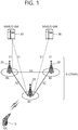
- FIG. 1 shows a wireless communication system to which the present invention is applied.
- the wireless communication system may also be referred to as an evolved-UMTS terrestrial radio access network (E-UTRAN) or a long term evolution (LTE)/LTE-A system.
- E-UTRAN evolved-UMTS terrestrial radio access network
- LTE long term evolution
- LTE-A long term evolution
- the E-UTRAN includes at least one base station (BS) 20 which provides a control plane and a user plane to a user equipment (UE) 10.
- the UE 10 may be fixed or mobile, and may be referred to as another terminology, such as a mobile station (MS), a user terminal (UT), a subscriber station (SS), a mobile terminal (MT), a wireless device, etc.
- the BS 20 is generally a fixed station that communicates with the UE 10 and may be referred to as another terminology, such as an evolved node-B (eNB), a base transceiver system (BTS), an access point, etc.
- eNB evolved node-B
- BTS base transceiver system
- access point etc.
- the BSs 20 are interconnected by means of an X2 interface.
- the BSs 20 are also connected by means of an S1 interface to an evolved packet core (EPC) 30, more specifically, to a mobility management entity (MME) through S1-MME and to a serving gateway (S-GW) through S1-U.
- EPC evolved packet core
- MME mobility management entity
- S-GW serving gateway
- the EPC 30 includes an MME, an S-GW, and a packet data network-gateway (P-GW).
- the MME has access information of the UE or capability information of the UE, and such information is generally used for mobility management of the UE.
- the S-GW is a gateway having an E-UTRAN as an end point.
- the P-GW is a gateway having a PDN as an end point.
- Layers of a radio interface protocol between the UE and the network can be classified into a first layer (L1), a second layer (L2), and a third layer (L3) based on the lower three layers of the open system interconnection (OSI) model that is well-known in the communication system.
- a physical (PHY) layer belonging to the first layer provides an information transfer service by using a physical channel
- a radio resource control (RRC) layer belonging to the third layer serves to control a radio resource between the UE and the network.
- the RRC layer exchanges an RRC message between the UE and the BS.
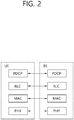
- FIG. 2 is a diagram showing a wireless protocol architecture for a user plane.
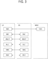
- FIG. 3 is a diagram showing a wireless protocol architecture for a control plane.
- the user plane is a protocol stack for user data transmission.
- the control plane is a protocol stack for control signal transmission.
- a PHY layer provides an upper layer with an information transfer service through a physical channel.
- the PHY layer is connected to a medium access control (MAC) layer which is an upper layer of the PHY layer through a transport channel.
- MAC medium access control
- Data is transferred between the MAC layer and the PHY layer through the transport channel.
- the transport channel is classified according to how and with what characteristics data is transferred through a radio interface.
- the physical channel may be modulated according to an Orthogonal Frequency Division Multiplexing (OFDM) scheme, and use the time and frequency as radio resources.
- OFDM Orthogonal Frequency Division Multiplexing
- the functions of the MAC layer include mapping between a logical channel and a transport channel and multiplexing and demultiplexing to a transport block that is provided through a physical channel on the transport channel of a MAC Service Data Unit (SDU) that belongs to a logical channel.
- SDU MAC Service Data Unit
- the MAC layer provides service to a Radio Link Control (RLC) layer through the logical channel.
- RLC Radio Link Control
- the functions of the RLC layer include the concatenation, segmentation, and reassembly of an RLC SDU.
- QoS Quality of Service
- RB Radio Bearer
- the RLC layer provides three types of operation mode: Transparent Mode (TM), Unacknowledged Mode (UM), and Acknowledged Mode (AM).
- TM Transparent Mode
- UM Unacknowledged Mode
- AM Acknowledged Mode
- AM RLC provides error correction through an Automatic Repeat Request (ARQ).
- ARQ Automatic Repeat Request
- the RRC layer is defined only on the control plane.
- the RRC layer is related to the configuration, reconfiguration, and release of radio bearers, and is responsible for control of logical channels, transport channels, and PHY channels.
- An RB means a logical route that is provided by the first layer (PHY layer) and the second layers (MAC layer, the RLC layer, and the PDCP layer) in order to transfer data between UE and a network.
- the function of a Packet Data Convergence Protocol (PDCP) layer on the user plane includes the transfer of user data and header compression and ciphering.
- the function of the PDCP layer on the user plane further includes the transfer and encryption/integrity protection of control plane data.
- PDCP Packet Data Convergence Protocol
- What an RB is configured means a process of defining the characteristics of a wireless protocol layer and channels in order to provide specific service and configuring each detailed parameter and operating method.
- An RB can be divided into two types of a Signaling RB (SRB) and a Data RB (DRB).
- SRB Signaling RB
- DRB Data RB
- the SRB is used as a passage through which an RRC message is transmitted on the control plane
- the DRB is used as a passage through which user data is transmitted on the user plane.
- the UE If RRC connection is established between the RRC layer of UE and the RRC layer of an E-UTRAN, the UE is in the RRC connected state. If not, the UE is in the RRC idle state.
- a downlink transport channel through which data is transmitted from a network to UE includes a broadcast channel (BCH) through which system information is transmitted and a downlink shared channel (SCH) through which user traffic or control messages are transmitted. Traffic or a control message for downlink multicast or broadcast service may be transmitted through the downlink SCH, or may be transmitted through an additional downlink multicast channel (MCH).
- BCH broadcast channel
- SCH downlink shared channel
- Traffic or a control message for downlink multicast or broadcast service may be transmitted through the downlink SCH, or may be transmitted through an additional downlink multicast channel (MCH).
- MCH downlink multicast channel
- an uplink transport channel through which data is transmitted from UE to a network includes a random access channel (RACH) through which an initial control message is transmitted and an uplink shared channel (SCH) through which user traffic or control messages are transmitted.
- RACH random access channel
- SCH uplink shared channel
- Logical channels that are placed over the transport channel and that are mapped to the transport channel include a broadcast control channel (BCCH), a paging control channel (PCCH), a common control channel (CCCH), a multicast control channel (MCCH), and a multicast traffic channel (MTCH).
- BCCH broadcast control channel
- PCCH paging control channel
- CCCH common control channel
- MCCH multicast control channel
- MTCH multicast traffic channel
- the physical channel includes several OFDM symbols in the time domain and several subcarriers in the frequency domain.
- One subframe includes a plurality of OFDM symbols in the time domain.
- An RB is a resources allocation unit, and includes a plurality of OFDM symbols and a plurality of subcarriers.
- each subframe may use specific subcarriers of specific OFDM symbols (e.g., the first OFDM symbol) of the corresponding subframe for a physical downlink control channel (PDCCH), that is, an L1/L2 control channel.
- PDCCH physical downlink control channel
- a Transmission Time Interval (TTI) is a unit time for subframe transmission.
- the RRC state of UE and an RRC connection method are described below.
- the RRC state means whether or not the RRC layer of UE is logically connected to the RRC layer of the E-UTRAN.
- a case where the RRC layer of UE is logically connected to the RRC layer of the E-UTRAN is referred to as an RRC connected state.
- a case where the RRC layer of UE is not logically connected to the RRC layer of the E-UTRAN is referred to as an RRC idle state.
- the E-UTRAN may check the existence of corresponding UE in the RRC connected state in each cell because the UE has RRC connection, so the UE may be effectively controlled.
- the E-UTRAN is unable to check UE in the RRC idle state, and a Core Network (CN) manages UE in the RRC idle state in each tracking area, that is, the unit of an area greater than a cell. That is, the existence or non-existence of UE in the RRC idle state is checked only for each large area. Accordingly, the UE needs to shift to the RRC connected state in order to be provided with common mobile communication service, such as voice or data.
- CN Core Network
- the UE When a user first powers UE, the UE first searches for a proper cell and remains in the RRC idle state in the corresponding cell.
- the UE in the RRC idle state establishes RRC connection with an E-UTRAN through an RRC connection procedure when it is necessary to set up the RRC connection, and shifts to the RRC connected state.
- a case where UE in the RRC idle state needs to set up RRC connection includes several cases.
- the cases may include a need to send uplink data for a reason, such as a call attempt by a user, and to send a response message as a response to a paging message received from an E-UTRAN.
- a Non-Access Stratum (NAS) layer placed over the RRC layer performs functions, such as session management and mobility management.
- functions such as session management and mobility management.
- EMM-REGISTERED EPS Mobility Management-REGISTERED
- EMM-DEREGISTERED EMM-DEREGISTERED
- the two states are applied to UE and the MME.
- UE is initially in the EMM-DEREGISTERED state.
- the UE performs a process of registering it with the corresponding network through an initial attach procedure. If the attach procedure is successfully performed, the UE and the MME become the EMM-REGISTERED state.
- an EPS Connection Management (ECM)-IDLE state In order to manage signaling connection between UE and the EPC, two types of states: an EPS Connection Management (ECM)-IDLE state and an ECM-CONNECTED state are defined.
- the two states are applied to UE and the MME.
- ECM-IDLE state When the UE in the ECM-IDLE state establishes RRC connection with the E-UTRAN, the UE becomes the ECM-CONNECTED state.
- the MME in the ECM-IDLE state becomes the ECM-CONNECTED state when it establishes S1 connection with the E-UTRAN.
- the E-UTRAN does not have information about the context of the UE.
- the UE in the ECM-IDLE state performs procedures related to UE-based mobility, such as cell selection or cell reselection, without a need to receive a command from a network.
- the mobility of the UE is managed in response to a command from a network. If the location of the UE in the ECM-IDLE state is different from a location known to the network, the UE informs the network of its corresponding location through a tracking area update procedure.
- System information includes essential information that needs to be known by UE in order for the UE to access a BS. Accordingly, the UE needs to have received all pieces of system information before accessing the BS, and needs to always have the up-to-date system information. Furthermore, the BS periodically transmits the system information because the system information is information that needs to be known by all UEs within one cell.
- the system information is divided into a Master Information Block (MIB) and a plurality of System Information Blocks (SIBs).
- MIB Master Information Block
- SIBs System Information Blocks
- the MIB may include the limited number of parameters which are the most essential and are most frequently transmitted in order to obtain other information from a cell.
- UE first discovers an MIB after downlink synchronization.
- the MIB may include information, such as a downlink channel bandwidth, a PHICH configuration, an SFN supporting synchronization and operating as a timing reference, and an eNB transmission antenna configuration.
- the MIB may be broadcasted on a BCH.
- SIB1 SystemInformationBlockType1 (SIB1) of included SIBs is included in a "SystemInformationBlockType1" message and transmitted.
- Other SIBs other than the SIB1 are included in a system information message and transmitted.
- the mapping of the SIBs to the system information message may be flexibly configured by a scheduling information list parameter included in the SIB1.
- each SIB is included in a single system information message. Only SIBs having the same scheduling required value (e.g. period) may be mapped to the same system information message.
- SIB2 SystemInformationBlockType2 (SIB2) is always mapped to a system information message corresponding to the first entry within the system information message list of a scheduling information list. A plurality of system information messages may be transmitted within the same period.
- the SIB1 and all of the system information messages are transmitted on a DL-SCH.
- the SIB1 may be channel-dedicated signaling including a parameter set to have the same value as an existing set value.
- the SIB1 may be included in an RRC connection re-establishment message and transmitted.
- the SIB1 includes information related to UE cell access and defines the scheduling of other SIBs.
- the SIB1 may include information related to the PLMN identifiers, Tracking Area Code (TAC), and cell ID of a network, a cell barring state indicative of whether a cell is a cell on which UE can camp, a required minimum reception level within a cell which is used as a cell reselection reference, and the transmission time and period of other SIBs.
- TAC Tracking Area Code
- the SIB2 may include radio resource configuration information common to all types of UE.
- the SIB2 may include information related to an uplink carrier frequency and uplink channel bandwidth, an RACH configuration, a page configuration, an uplink power control configuration, a sounding reference signal configuration, a PUCCH configuration supporting ACK/NACK transmission, and a PUSCH configuration.
- the UE may apply a procedure for obtaining system information and for detecting a change of system information to only a PCell.
- the E-UTRAN may provide all types of system information related to an RRC connection state operation through dedicated signaling.
- the E-UTRAN may release a considered SCell and add the considered SCell later. This may be performed along with a single RRC connection re-establishment message.
- the E-UTRAN may set a value broadcast within a considered SCell and other parameter value through dedicated signaling.
- the UE needs to guarantee the validity of a specific type of system information.
- system information is called required system information.
- the required system information may be defined as follows.
- the UE needs to have the valid version of the MIB and the SIB1 in addition to the SIB2 to SIB8. This may comply with the support of a considered RAT.
- the UE needs to have the valid version of the MIB, SIB1, and SIB2.
- the validity of system information may be guaranteed up to a maximum of 3 hours after being obtained.
- service that is provided to UE by a network may be classified into three types as follows. Furthermore, the UE differently recognizes the type of cell depending on what service may be provided to the UE. In the following description, a service type is first described, and the type of cell is described.
- Limited service this service provides emergency calls and an Earthquake and Tsunami Warning System (ETWS), and may be provided by an acceptable cell.
- ETWS Earthquake and Tsunami Warning System
- this service means public service for common uses, and may be provided by a suitable cell (or a normal cell).
- this service means service for communication network operators. This cell may be used by only communication network operators, but may not be used by common users.
- the type of cell may be classified as follows.
- FIG. 4 is a flowchart illustrating the operation of UE in the RRC idle state.
- FIG. 4 illustrates a procedure in which UE that is initially powered on experiences a cell selection process, registers it with a network, and then performs cell reselection if necessary.
- the UE selects Radio Access Technology (RAT) in which the UE communicates with a Public Land Mobile Network (PLMN), that is, a network from which the UE is provided with service (S410).
- RAT Radio Access Technology
- PLMN Public Land Mobile Network
- S410 a network from which the UE is provided with service
- Information about the PLMN and the RAT may be selected by the user of the UE, and the information stored in a Universal Subscriber Identity Module (USIM) may be used.
- USIM Universal Subscriber Identity Module
- the UE selects a cell that has the greatest value and that belongs to cells having measured BS and signal intensity or quality greater than a specific value (cell selection) (S420).
- cell selection a specific value
- the UE that is powered off performs cell selection, which may be called initial cell selection.
- a cell selection procedure is described later in detail.
- the UE receives system information periodically by the BS.
- the specific value refers to a value that is defined in a system in order for the quality of a physical signal in data transmission/reception to be guaranteed. Accordingly, the specific value may differ depending on applied RAT.
- the UE performs a network registration procedure (S430).
- the UE registers its information (e.g., an IMSI) with the network in order to receive service (e.g., paging) from the network.
- the UE does not register it with a network whenever it selects a cell, but registers it with a network when information about the network (e.g., a Tracking Area Identity (TAI)) included in system information is different from information about the network that is known to the UE.
- TAI Tracking Area Identity
- the UE performs cell reselection based on a service environment provided by the cell or the environment of the UE (S440). If the value of the intensity or quality of a signal measured based on a BS from which the UE is provided with service is lower than that measured based on a BS of a neighboring cell, the UE selects a cell that belongs to other cells and that provides better signal characteristics than the cell of the BS that is accessed by the UE. This process is called cell reselection differently from the initial cell selection of the No. 2 process. In this case, temporal restriction conditions are placed in order for a cell to be frequently reselected in response to a change of signal characteristic. A cell reselection procedure is described later in detail.
- FIG. 5 is a flowchart illustrating a process of establishing RRC connection.
- the UE sends an RRC connection request message that requests RRC connection to a network (S510).
- the network sends an RRC connection establishment message as a response to the RRC connection request (S520). After receiving the RRC connection establishment message, the UE enters RRC connected mode.
- the UE sends an RRC connection establishment complete message used to check the successful completion of the RRC connection to the network (S530).
- FIG. 6 is a flowchart illustrating an RRC connection reconfiguration process.
- An RRC connection reconfiguration is used to modify RRC connection. This is used to establish/modify/release RBs, perform handover, and set up/modify/release measurements.
- a network sends an RRC connection reconfiguration message for modifying RRC connection to UE (S610).
- the UE sends an RRC connection reconfiguration complete message used to check the successful completion of the RRC connection reconfiguration to the network (S620).
- PLMN public land mobile network
- the PLMN is a network which is disposed and operated by a mobile network operator. Each mobile network operator operates one or more PLMNs. Each PLMN may be identified by a Mobile Country Code (MCC) and a Mobile Network Code (MNC). PLMN information of a cell is included in system information and broadcasted.
- MCC Mobile Country Code
- MNC Mobile Network Code
- PLMN selection In PLMN selection, cell selection, and cell reselection, various types of PLMNs may be considered by the terminal.
- HPLMN Home PLMN
- MCC and MNC matching with MCC and MNC of a terminal IMSI PLMN having MCC and MNC matching with MCC and MNC of a terminal IMSI.
- Equivalent HPLMN PLMN serving as an equivalent of an HPLMN.
- Registered PLMN PLMN successfully finishing location registration.
- ELMN Equivalent PLMN
- the terminal When a general service is provided to the terminal through the HPLMN or the EHPLMN, the terminal is not in a roaming state. Meanwhile, when the service is provided to the terminal through a PLMN except for the HPLMN/EHPLMN, the terminal is in the roaming state.
- the PLMN refers to a Visited PLMN (VPLMN).
- the PLMN is a network that is deployed or operated by a mobile network operator. Each mobile network operator operates one or more PLMNs. Each PLMN may be identified by Mobile Country Code (MCC) and Mobile Network Code (MNC). Information about the PLMN of a cell is included in system information and broadcasted. The UE attempts to register it with the selected PLMN. If registration is successful, the selected PLMN becomes a Registered PLMN (RPLMN). The network may signalize a PLMN list to the UE.
- MCC Mobile Country Code
- MNC Mobile Network Code
- PLMNs included in the PLMN list may be considered to be PLMNs, such as RPLMNs.
- the UE registered with the network needs to be able to be always reachable by the network. If the UE is in the ECM-CONNECTED state (identically the RRC connection state), the network recognizes that the UE is being provided with service. If the UE is in the ECM-IDLE state (identically the RRC idle state), however, the situation of the UE is not valid in an eNB, but is stored in the MME. In such a case, only the MME is informed of the location of the UE in the ECM-IDLE state through the granularity of the list of Tracking Areas (TAs).
- a single TA is identified by a Tracking Area Identity (TAI) formed of the identifier of a PLMN to which the TA belongs and Tracking Area Code (TAC) that uniquely expresses the TA within the PLMN.
- TAI Tracking Area Identity
- the UE selects a cell that belongs to cells provided by the selected PLMN and that has signal quality and characteristics on which the UE is able to be provided with proper service.
- the terminal When power is turned-on or the terminal is located in a cell, the terminal performs procedures for receiving a service by selecting/reselecting a suitable quality cell.
- a terminal in an RRC idle state should prepare to receive a service through the cell by always selecting a suitable quality cell. For example, a terminal where power is turned-on just before should select the suitable quality cell to be registered in a network. If the terminal in an RRC connection state enters in an RRC idle state, the terminal should selects a cell for stay in the RRC idle state. In this way, a procedure of selecting a cell satisfying a certain condition by the terminal in order to be in a service idle state such as the RRC idle state refers to cell selection. Since the cell selection is performed in a state that a cell in the RRC idle state is not currently determined, it is important to select the cell as rapid as possible. Accordingly, if the cell provides a wireless signal quality of a predetermined level or greater, although the cell does not provide the best wireless signal quality, the cell may be selected during a cell selection procedure of the terminal.
- a method and a procedure of selecting a cell by a terminal in a 3GPP LTE is described with reference to 3GPP TS 36.304 V8.5.0 (2009-03) "User Equipment (UE) procedures in idle mode (Release 8) ".
- UE User Equipment
- a cell selection process is basically divided into two types.
- the first is an initial cell selection process.
- UE does not have preliminary information about a wireless channel. Accordingly, the UE searches for all wireless channels in order to find out a proper cell. The UE searches for the strongest cell in each channel. Thereafter, if the UE has only to search for a suitable cell that satisfies a cell selection criterion, the UE selects the corresponding cell.
- the UE may select the cell using stored information or using information broadcasted by the cell. Accordingly, cell selection may be fast compared to an initial cell selection process. If the UE has only to search for a cell that satisfies the cell selection criterion, the UE selects the corresponding cell. If a suitable cell that satisfies the cell selection criterion is not retrieved though such a process, the UE performs an initial cell selection process.
- the cell selection criterion may be defined as below equation 1.
- Srxlev Q rxlevmeas ⁇ Q rxlevmin + Q rxlevminoffset ⁇ Pcompensation
- Squal Q qualmeas ⁇ Q qualmin + Q qualminoffset
- the variables in the equation 1 may be defined as below table 1.
- Table 1 Srxlev Cell selection RX level value (dB) Squal Cell selection quality value (dB) Q rxlevmeas Measured cell RX level value (RSRP) Q qualmeas Measured cell quality value (RSRQ) Q rxlevmin Minimum required RX level in the cell (dBm) Q qualmin Minimum required quality level in the cell (dB) Q rxlevminoffset Offset to the signalled Q rxlevmin taken into account in the Srxlev evaluation as a result of a periodic search for a higher priority PLMN while camped normally in a VPLMN Q qualminoffset Offset to the signalled Q qualmin taken into account in the Squal evaluation as a result of a periodic search for a higher priority PLMN while camped normally in a VPLMN Pcompensation max(P EMAX -P PowerClass , 0) (dB) P EMAX Maximum TX power level
- Signalled values i.e., Q rxlevminoffset and Q qualminoffset , may be applied to a case where cell selection is evaluated as a result of periodic search for a higher priority PLMN during a UE camps on a normal cell in a VPLMN.
- the UE may perform the cell selection evaluation by using parameter values stored in other cells of the higher priority PLMN.
- the intensity or quality of a signal between the UE and a BS may be changed due to a change in the mobility or wireless environment of the UE. Accordingly, if the quality of the selected cell is deteriorated, the UE may select another cell that provides better quality. If a cell is reselected as described above, the UE selects a cell that provides better signal quality than the currently selected cell. Such a process is called cell reselection. In general, a basic object of the cell reselection process is to select a cell that provides UE with the best quality from a viewpoint of the quality of a radio signal.
- a network may determine priority corresponding to each frequency, and may inform the UE of the determined priorities.
- the UE that has received the priorities preferentially takes into consideration the priorities in a cell reselection process compared to a radio signal quality criterion.
- the following cell reselection methods may be present according to the RAT and frequency characteristics of the cell.
- UE measures the quality of a serving cell and neighbor cells for cell reselection.
- cell reselection is performed based on a cell reselection criterion.
- the cell reselection criterion has the following characteristics in relation to the measurements of a serving cell and neighbor cells.
- Intra-frequency cell reselection is basically based on ranking.
- Ranking is a task for defining a criterion value for evaluating cell reselection and numbering cells using criterion values according to the size of the criterion values.
- a cell having the best criterion is commonly called the best-ranked cell.
- the cell criterion value is based on the value of a corresponding cell measured by UE, and may be a value to which a frequency offset or cell offset has been applied, if necessary.
- Inter-frequency cell reselection is based on frequency priority provided by a network.
- UE attempts to camp on a frequency having the highest frequency priority.
- a network may provide frequency priority that will be applied by UEs within a cell in common through broadcasting signaling, or may provide frequency-specific priority to each UE through UE-dedicated signaling.
- a cell reselection priority provided through broadcast signaling may refer to a common priority.
- a cell reselection priority for each terminal set by a network may refer to a dedicated priority. If receiving the dedicated priority, the terminal may receive a valid time associated with the dedicated priority together. If receiving the dedicated priority, the terminal starts a validity timer set as the received valid time together therewith. While the valid timer is operated, the terminal applies the dedicated priority in the RRC idle mode. If the valid timer is expired, the terminal discards the dedicated priority and again applies the common priority.
- a network may provide UE with a parameter (e.g., a frequency-specific offset) used in cell reselection for each frequency.
- a parameter e.g., a frequency-specific offset
- a network may provide UE with a Neighboring Cell List (NCL) used in cell reselection.
- NCL Neighboring Cell List
- the NCL includes a cell-specific parameter (e.g., a cell-specific offset) used in cell reselection.
- a network may provide UE with a cell reselection black list used in cell reselection. The UE does not perform cell reselection on a cell included in the black list.
- a ranking criterion used to apply priority to a cell is defined as in Equation 1.
- Rs Qmeas , s + Qhyst
- Rn Qmeas , s ⁇ Qoffset
- Rs is the ranking criterion of a serving cell
- Rn is the ranking criterion of a neighbor cell
- Qmeas,s is the quality value of the serving cell measured by UE
- Qmeas,n is the quality value of the neighbor cell measured by UE
- Qhyst is the hysteresis value for ranking
- Qoffset is an offset between the two cells.
- ranking priority is frequency changed as a result of the change, and UE may alternately reselect the twos.
- Qhyst is a parameter that gives hysteresis to cell reselection so that UE is prevented from to alternately reselecting two cells.
- UE measures RS of a serving cell and Rn of a neighbor cell according to the above equation, considers a cell having the greatest ranking criterion value to be the best-ranked cell, and reselects the cell.
- UE may be checked that the quality of a cell is the most important criterion in cell reselection. If a reselected cell is not a suitable cell, UE excludes a corresponding frequency or a corresponding cell from the subject of cell reselection.
- RLF Radio Link Failure
- the UE continues to perform measurements in order to maintain the quality of a radio link with a serving cell from which the UE receives service.
- the UE determines whether or not communication is impossible in a current situation due to the deterioration of the quality of the radio link with the serving cell. If communication is almost impossible because the quality of the serving cell is too low, the UE determines the current situation to be an RLF.
- the UE abandons maintaining communication with the current serving cell, selects a new cell through cell selection (or cell reselection) procedure, and attempts RRC connection re-establishment with the new cell.
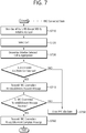
- FIG. 7 is a diagram illustrating an RRC connection re-establishment procedure.
- UE stops using all the radio bearers that have been configured other than a Signaling Radio Bearer (SRB) #0, and initializes a variety of kinds of sublayers of an Access Stratum (AS) (S710). Furthermore, the UE configures each sublayer and the PHY layer as a default configuration. In this process, the UE maintains the RRC connection state.
- SRB Signaling Radio Bearer
- AS Access Stratum
- the UE performs a cell selection procedure for performing an RRC connection reconfiguration procedure (S720).
- the cell selection procedure of the RRC connection re-establishment procedure may be performed in the same manner as the cell selection procedure that is performed by the UE in the RRC idle state, although the UE maintains the RRC connection state.
- the UE determines whether or not a corresponding cell is a suitable cell by checking the system information of the corresponding cell (S730). If the selected cell is determined to be a suitable E-UTRAN cell, the UE sends an RRC connection re-establishment request message to the corresponding cell (S740).
- the UE stops the RRC connection re-establishment procedure and enters the RRC idle state (S750).
- the UE may be implemented to finish checking whether the selected cell is a suitable cell through the cell selection procedure and the reception of the system information of the selected cell. To this end, the UE may drive a timer when the RRC connection re-establishment procedure is started. The timer may be stopped if it is determined that the UE has selected a suitable cell. If the timer expires, the UE may consider that the RRC connection re-establishment procedure has failed, and may enter the RRC idle state. Such a timer is hereinafter called an RLF timer. In LTE spec TS 36.331, a timer named "T311" may be used as an RLF timer. The UE may obtain the set value of the timer from the system information of the serving cell.
- a cell sends an RRC connection re-establishment message to the UE.
- the UE that has received the RRC connection re-establishment message from the cell reconfigures a PDCP sublayer and an RLC sublayer with an SRB1. Furthermore, the UE calculates various key values related to security setting, and reconfigures a PDCP sublayer responsible for security as the newly calculated security key values. Accordingly, the SRB 1 between the UE and the cell is open, and the UE and the cell may exchange RRC control messages. The UE completes the restart of the SRB1, and sends an RRC connection re-establishment complete message indicative of that the RRC connection re-establishment procedure has been completed to the cell (S760).
- the cell sends an RRC connection re-establishment reject message to the UE.
- the cell and the UE perform an RRC connection reconfiguration procedure. Accordingly, the UE recovers the state prior to the execution of the RRC connection re-establishment procedure, and the continuity of service is guaranteed to the upmost.
- FIG. 8 illustrates substates which may be owned by UE in the RRC_IDLE state and a substate transition process.
- the initial cell selection process may be performed when there is no cell information stored with respect to a PLMN or if a suitable cell is not discovered.
- the UE transits to any cell selection state (S802).
- the any cell selection state is the state in which the UE has not camped on a suitable cell and an acceptable cell and is the state in which the UE attempts to discover an acceptable cell of a specific PLMN on which the UE may camp. If the UE has not discovered any cell on which it may camp, the UE continues to stay in the any cell selection state until it discovers an acceptable cell.
- the normal camp state refers to the state in which the UE has camped on the suitable cell. In this state, the UE may select and monitor a paging channel based on information provided through system information and may perform an evaluation process for cell reselection.
- a cell reselection evaluation process (S804) is caused in the normal camp state (S803), the UE performs a cell reselection evaluation process (S804). If a suitable cell is discovered in the cell reselection evaluation process (S804), the UE transits to the normal camp state (S803) again.
- the UE transmits to any cell camp state (S805).
- the any cell camp state is the state in which the UE has camped on the acceptable cell.
- the UE may select and monitor a paging channel based on information provided through system information and may perform the evaluation process (S806) for cell reselection. If an acceptable cell is not discovered in the evaluation process (S806) for cell reselection, the UE transits to the any cell selection state (S802).
- D2D device-to-device
- ProSe proximity service
- the ProSe includes ProSe direction communication and ProSe direct discovery.
- the ProSe direct communication is communication performed between two or more proximate UEs.
- the UEs may perform communication by using a protocol of a user plane.
- a ProSe-enabled UE implies a UE supporting a procedure related to a requirement of the ProSe.
- the ProSe-enabled UE includes both of a public safety UE and a non-public safety UE.
- the public safety UE is a UE supporting both of a function specified for a public safety and a ProSe procedure
- the non-public safety UE is a UE supporting the ProSe procedure and not supporting the function specified for the public safety.
- ProSe direct discovery is a process for discovering another ProSe-enabled UE adjacent to ProSe-enabled UE. In this case, only the capabilities of the two types of ProSe-enabled UE are used.
- EPC-level ProSe discovery means a process for determining, by an EPC, whether the two types of ProSe-enabled UE are in proximity and notifying the two types of ProSe-enabled UE of the proximity.
- the ProSe direct communication may be referred to as D2D communication
- the ProSe direct discovery may be referred to as D2D discovery.
- FIG. 9 shows a basic structure for ProSe.
- the basic structure for ProSe includes an E-UTRAN, an EPC, a plurality of types of UE including a ProSe application program, a ProSe application server (a ProSe APP server), and a ProSe function.
- the EPC represents an E-UTRAN core network configuration.
- the EPC may include an MME, an S-GW, a P-GW, a policy and charging rules function (PCRF), a home subscriber server (HSS) and so on.
- PCRF policy and charging rules function
- HSS home subscriber server
- the ProSe APP server is a user of a ProSe capability for producing an application function.
- the ProSe APP server may communicate with an application program within UE.
- the application program within UE may use a ProSe capability for producing an application function.
- the ProSe function may include at least one of the followings, but is not necessarily limited thereto.
- ProSe direct communication is communication mode in which two types of public safety UE can perform direct communication through a PC 5 interface. Such communication mode may be supported when UE is supplied with services within coverage of an E-UTRAN or when UE deviates from coverage of an E-UTRAN.
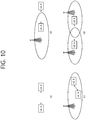
- FIG. 10 shows the deployment examples of types of UE performing ProSe direct communication and cell coverage.
- types of UE A and B may be placed outside cell coverage.
- UE A may be placed within cell coverage
- UE B may be placed outside cell coverage.
- types of UE A and B may be placed within single cell coverage.
- UE A may be placed within coverage of a first cell
- UE B may be placed within coverage of a second cell.
- ProSe direct communication may be performed between types of UE placed at various positions as in FIG. 10 .
- the following IDs may be used in ProSe direct communication.
- a source layer-2 ID this ID identifies the sender of a packet in the PC 5 interface.
- a destination layer-2 ID this ID identifies the target of a packet in the PC 5 interface.
- SA L1 ID this ID is the ID of scheduling assignment (SA) in the PC 5 interface.
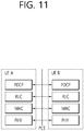
- FIG. 11 shows a user plane protocol stack for ProSe direct communication.
- the PC 5 interface includes a PDCH, RLC, MAC, and PHY layers.
- An MAC header may include a source layer-2 ID and a destination layer-2 ID.
- ProSe-enabled UE may use the following two types of mode for resource assignment for ProSe direct communication.
- Mode 1 is mode in which resources for ProSe direct communication are scheduled by an eNB.
- UE needs to be in the RRC_CONNECTED state in order to send data in accordance with mode 1.
- the UE requests a transmission resource from an eNB.
- the eNB performs scheduling assignment and schedules resources for sending data.
- the UE may send a scheduling request to the eNB and send a ProSe Buffer Status Report (BSR).
- BSR ProSe Buffer Status Report
- the eNB has data to be subjected to ProSe direct communication by the UE based on the ProSe BSR and determines that a resource for transmission is required.
- Mode 2 is mode in which UE directly selects a resource.
- UE directly selects a resource for ProSe direct communication in a resource pool.
- the resource pool may be configured by a network or may have been previously determined.
- the UE is considered to be placed within coverage of the eNB.
- mode 2 may be applied. If the UE is placed within the coverage, the UE may use mode 1 or mode 2 depending on the configuration of an eNB.
- UE may change mode from mode 1 to mode 2 or from mode 2 to mode 1.
- ProSe direct discovery refers to a procedure that is used for ProSe-enabled UE to discover another ProSe-enabled UE in proximity and is also called D2D direct discovery.
- E-UTRA radio signals through the PC 5 interface may be used.
- Information used in ProSe direct discovery is hereinafter called discovery information.
- FIG. 12 shows the PC 5 interface for D2D direct discovery.
- the PC 5 interface includes an MAC layer, a PHY layer, and a ProSe Protocol layer, that is, a higher layer.
- the higher layer (the ProSe Protocol) handles the permission of the announcement and monitoring of discovery information.
- the contents of the discovery information are transparent to an access stratum (AS).
- the ProSe Protocol transfers only valid discovery information to the AS for announcement.
- the MAC layer receives discovery information from the higher layer (the ProSe Protocol). An IP layer is not used to send discovery information. The MAC layer determines a resource used to announce discovery information received from the higher layer. The MAC layer produces an MAC protocol data unit (PDU) for carrying discovery information and sends the MAC PDU to the physical layer. An MAC header is not added.
- PDU MAC protocol data unit
- a base station provides a resource pool configuration for announcement of the discovered information to terminals.
- the configuration is included in a system information block (SIB) to be signaled by a broadcast scheme.
- SIB system information block
- the configuration may be provided while being included in a terminal specific RRC message.
- the configuration may be broadcast signaling of another layer except for an RRC message or terminal specific signaling.
- the terminal autonomously selects the resource from an indicated resource pool and announces the discovery information by using the selected resource.
- the terminal may announce the discovery information through an arbitrarily selected resource during each discovery period.
- the type 2 is a method for assigning a resource for announcing discovery information in a UE-specific manner.
- UE in the RRC_CONNECTED state may request a resource for discovery signal announcement from an eNB through an RRC signal.
- the eNB may announce a resource for discovery signal announcement through an RRC signal.
- a resource for discovery signal monitoring may be assigned within a resource pool configured for types of UE.
- An eNB 1) may announce a type 1 resource pool for discovery signal announcement to UE in the RRC_IDLE state through the SIB. Types of UE whose ProSe direct discovery has been permitted use the type 1 resource pool for discovery information announcement in the RRC_IDLE state.
- the eNB 2) announces that the eNB supports ProSe direct discovery through the SIB, but may not provide a resource for discovery information announcement. In this case, UE needs to enter the RRC_CONNECTED state for discovery information announcement.
- An eNB may configure that UE has to use a type 1 resource pool for discovery information announcement or has to use a type 2 resource through an RRC signal in relation to UE in the RRC_CONNECTED state.
- ARQ Automatic Repeat request
- HARQ hybrid ARQ
- ACK acknowledge message
- NACK negative-ACK
- a receiver transmits a NACK message to a transmitter in the case that the receiver is unable to decode a received subframe.
- the receiver stores the subframe received already in a buffer for predetermined time duration, and increases a reception succeed rate by combining it with the subframe received already when the subframe is retransmitted.
- the HARQ scheme which is more efficient than the ARQ scheme has been widely used.
- the HARQ scheme may be divided into synchronous HARQ and asynchronous HARQ according to transmission timing, and may be divided into channel-adaptive scheme and channel-non-adaptive scheme according to whether it reflects a channel state for an amount of resource which is used in retransmission.
- a MAC entity In order to perform an uplink transmission through a UL-SCH, except a non-adaptive HARQ retransmission, a MAC entity needs to have a valid uplink grant.
- AUE may dynamically receive the uplink grant through a PDCCH, and may receive the uplink grant through a random access response.
- the UE may be configured with the uplink grant semi-persistently.
- a MAC layer needs to receive HARQ information from a lower layer.
- the MAC layer may receive up to two grants for each HARQ process.
- a UE receives scheduling information such as a DL grant and a UL grant through a PDCCH, and based on the scheduling information, the UE performs an operation of receiving a PDSCH or transmitting a PUSCH.
- a DL grant and a PDSCH are received in the same subframe.
- a scheduled PUSCH is transmitted by the UL grant.
- a PUSCH is transmitted after four subframes from the subframe in which the UL grant is received.
- LTE/LTE-A also provides semi-persistent scheduling (SPS).
- SPS semi-persistent scheduling
- the SPS may be applied to downlink or uplink.
- the SPS may inform a certain subframe in which the semi-persistent transmission (PUSCH)/reception (PDSCH) is performed to a UE through a higher layer signal such as radio resource control (RRC), and it is assumed that the signal informing it is SPS configuration.
- RRC radio resource control
- the SPS configuration may be provided through a higher layer signal such as RRC, and various parameters may be included in the SPS configuration.
- the parameters may be a period and an offset value of a subframe, for example.
- the Table below is an example of the SPS configuration.
- the SPS configuration includes various parameters.
- 'semiPersistSchedIntervalDL' represents an interval of semi-persistent scheduling in downlink in a unit of subframe.
- 'semiPersistSchedIntervalUL' represents an interval of semi-persistent scheduling in uplink in a unit of subframe.
- 'numberOfConfSPS-Processes' represents the number of HARQ processes setup for semi-persistent scheduling.
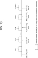
- FIG. 13 illustrates a UE operation according to the SPS.
- a UE receives the SPS configuration through RRC signaling.
- the resources allocated through the SPS configuration are exemplified as subframes 131-1, 131-2, ..., 131-N, ..., 131-M, and 131-(M+1).
- the UE identifies that SPS transmission/reception may occur.
- the UE receives a signal that activates or releases the SPS transmission through a PDCCH, the UE performs or releases the SPS transmission/reception. That is, even in the case that the UE receives the SPS configuration through RRC signaling, the UE performs the SPS transmission/reception immediately.
- the UE performs the SPS transmission/reception in a subframe that corresponds to a subframe period and an offset value allocated through RRC signaling by applying modulation and coding rate according to a frequency resource (resource block) according to a resource block allocation designated by the PDCCH and MCS information.
- the UE receives SPS release signal through the PDCCH, the UE stops the SPS transmission/reception.
- the SPS transmission/reception stopped as such is restarted when the UE receives a PDCCH (SPS reactivation PDCCH) that includes SPS activation signal again by using the frequency resource, MCS, and the like designated in the corresponding PDCCH.
- SPS reactivation PDCCH PDCCH
- FIG. 13 shows an example that a UE receives SPS activation PDCCH (PDCCH including SPS activation signal) in subframe 131-2, and receives SPS release PDCCH (PDCCH including SPS release signal) in subframe 131-(M+1).
- the UE may receive a PDSCH according to the SPS in subframes 131-N, 131-M, and so on.
- an eNB is unable to know an actual traffic generation time (timing) in the UE. Even in the case that the actual traffic generation time in the UE is well defined (e.g., even in the case that it is defined to generate a traffic periodically), the eNB does not know it, and accordingly, the eNB may not configure an optimal SPS configuration.
- FIG. 14 illustrates a problem that may occur in the case that SPS period T of SPS resources and a generation period T' of a traffic actually generated in a UE are different.
- the resources allocated according to the SPS configuration has period T, and a traffic occurs with period T' in the UE.
- a part of traffic generation timing e.g., 143 and 144 may not correspond to the resource (transmission opportunity) allocated according to the SPS configuration.
- a period of a signal generated periodically in a vehicle may be slightly changed depending on speed and direction of the vehicle.
- a vehicle is allocated with SPS resources periodically from a network to transmit signals periodically generated in the vehicle but speed and direction of the vehicle are changed and accordingly, a period of the generated signals is also changed, it may be difficult to transmit the generated signal in the SPS resources.
- the present invention proposes a method for a UE to inform the traffic information that informs a timing pattern of data traffic to an eNB.
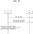
- FIG. 15 illustrates a UE operation according to an embodiment of the present invention.
- a UE transmits traffic information to an eNB (step, S151).
- the traffic information may be information that informs or characterizes a transmission timing of the data traffic transmitted by the UE.
- the traffic information may include 1) a period of traffic generation in the UE and 2) information that may inform traffic generation timing in the UE.
- the information that may inform traffic generation timing in the UE is as follows. For example, when there is a reference time that the UE and the eNB know commonly, the traffic generation timing in the UE may be informed by an offset value with respect to the reference time, and in this case, the offset value may correspond to the information that may inform traffic generation timing in the UE.
- the offset value may represent a time difference between the reference time and the time when traffic is actually generated in the UE.
- the reference time may be represented, for example, by subframe #K of system frame number (SFN) #L. Both of the L and the K may be zero.
- the UE may report the traffic generation timing with margin by considering a situation that the traffic generation timing may be delayed or changed. Then, even in the case that the traffic generation timing is delayed within the margin range, it may not lose the SPS transmission opportunity.
- the traffic information may further include the following information.
- the traffic information may include end-to-end latency requirements for the corresponding traffic.
- a UE may indicate that end-to-end latency requirement is 100 milliseconds (ms). That is, the traffic information may include information indicating a latency requirement which is requested for the traffic generated by the UE.
- the traffic information may also include information indicating a final destination type of the corresponding traffic.
- the final destination type may be a UE, a cloud server of an IP domain, a part of radio network (RRH), and the like.
- the UE may transmit the traffic information when at least one of the following conditions is satisfied.
- the UE may provide the traffic information to the eNB using an RRC message. That is, the UE may include the traffic information in the RRC message transmitted to a network. The UE may include the traffic information in the RRC message generated by the UE in order to inform services such as V2X service and V2V transmission.
- the eNB may provide/configure the SPS configuration determined based on the traffic information (step, S152). For example, in the SPS configuration associated with the traffic information, the SPS period may be identically configured with the traffic generation period reported by the UE. Alternatively, in the case that the SPS period is selected among a plurality of candidate values, even in the case that the SPS period is not the same as the traffic generation period reported by the UE, the SPS period may be configured as the value of which difference from the traffic generation period is the smallest.
- the UE transmits/receives a signal in the resource according to the SPS configuration (step, S153).
- the signal may be vehicle-to-everything (V2X) signal or D2D signal.
- T_process it is preferable that the transmission timing according to the SPS that a network set to a UE is configured after as much as minimum T_process from the timing when the traffic is generated in an application of the UE. Accordingly, in the case that the traffic generation timing provided by the UE through the traffic information indicates the timing when the traffic is generated in an application layer, it may be required to report T_process also required for the UE. That is, the traffic information may be transmitted together with the traffic generation timing and T_process information in an application layer.
- the network may setup the transmission timing (transmission resource and transmission opportunity) according to the SPS by considering both of the timing when the traffic is generated in an application layer of the UE and the T_process.
- the traffic generation timing provided by the UE through the traffic information indicates transmission timing in a physical layer, it may not be required to report T_process. However, the UE is required to report the traffic generation timing considering the T_process to the network.
- the traffic information may be information that characterizes a traffic generation pattern of a UE in a time domain.
- the traffic generation timing that a UE reports to an eNB may be slightly different from the timing when traffic is actually generated in the UE. That is, slight deviation may occur, and such deviation may be generated in each of the SPS transmissions.
- the UE may transmit the SPS adjustment request through an uplink control channel.
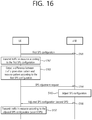
- FIG. 16 illustrates an example that a UE transmits SPS adjustment request.
- a UE receives a first SPS configuration from an eNB (step, S161).
- the UE transmits traffic in the resource according to the first SPS configuration (step, S162).
- the UE detects a difference between a traffic generation pattern and a resource pattern according to the first SPS configuration (step, S163).
- the UE transmits the SPS adjustment request that requests an adjustment of the first SPS configuration to a network (step, S164).
- the eNB After the eNB adjusts the SPS configuration (step, S165), the eNB provides an adjusted SPS, that is, a second SPS configuration to the UE (step, S166). The UE transmits traffic in the resource according to the adjusted SPS configuration (second SPS configuration) (step, S167).
- the SPS adjustment request may include at least one of the followings:
- AS access stratum
- the UE may inform that the UE is not going to use the specific SPS transmission opportunity to the eNB.
- the UE has a grant set for subframe N. That is, the UE has the SPS transmission opportunity in subframe N.
- the grant may indicate a resource of which use is allowed in subframe N.
- the UE may inform this to the eNB.
- the UE may inform this to the eNB using an uplink control channel. Through such an operation, the UE informs that the UE is not going to use the SPS transmission opportunity in subframe N to the eNB, and therefore, it may be prevented to waste the SPS transmission opportunity.
- the eNB may schedule subframe N to other UE.
- the time denoted by T_deadline may set to the UE by the network.
- the UE provides the traffic information to the eNB.
- the UE may not report the traffic information, but MME or other network node may inform the traffic information of the UE to the eNB.
- MME or other network node may know the traffic generation for the UE from the UE context setup for the UE or adjustment process, the MME or other network may inform the traffic information of the UE to the eNB.
- An eNB may setup one or a plurality of SPS configurations to a UE.
- Each SPS configuration may provide a grant which is periodically setup to a UE. Similar to the conventional SPS configuration, the SPS configuration according to the present invention may also provide a grant, which is periodically setup to a UE, that is, resource allocation information. At this time, a parameter included in an SPS configuration may be different from a corresponding parameter included in another SPS configuration. For example, an eNB may provide a first SPS configuration and a second SPS configuration to a UE. Each SPS configuration may include an SPS period, an offset value, and the like as parameters. In this case, the value of the SPS period parameter included in the first SPS configuration and the value of the SPS period parameter included in the second SPS configuration may be different with each other.
- Each SPS configuration may be associated with a specific logical channel, and the data transmitted through the specific logical channel may be transmitted using the SPS configuration associated with the specific logical channel.
- an eNB may inform an identity (ID) of the logical channel which is associated with the SPS configuration.
- the association between the logical channel and the SPS configuration may be association between a particular QoS and a particular SPS configuration. That is, it is available to associate each of traffics with different SPS configurations for transmitting traffic that has different QoS requirements.
- the SPS transmission opportunities according to the conventional SPS configuration may be characterized as a periodic transmission opportunity in a time domain.
- the SPS transmission may be performed in subframes having period N such as n+N subframe, n+2N subframe and n+3N subframe
- a UE has an SPS transmission opportunity in the n+N subframe, n+2N subframe and n+3N subframe.
- an eNB may setup more flexible SPS configuration using the following method.
- the transmission opportunities may be indicated by a bitmap pattern.
- value 1 corresponds to a grant configured for a transmission
- value 0 does not correspond to a grant configured for a transmission.
- N 1 for the convenience of description.
- bitmap may be given as 40 bits for the 40 subframes as below.
- a leftmost bit may correspond to a reference timing that a UE and a network commonly know.
- the leftmost bit may correspond to subframe #N in a subframe corresponding to system frame number (SFN) #M.
- SFN system frame number
- both of N and M may be zero.
- a bit located next to the leftmost bit may correspond to subframe #N+1 of SFN #M.
- a bit denoted by 'Y' may represent a grant configured for a transmission in a corresponding subframe
- a bit denoted by 'x' may represent that there is not grant configured for a transmission in a corresponding subframe. That is, in a subframe corresponding to a bit which is denoted by 'Y', a UE may perform an SPS transmission, and in a subframe corresponding to a bit which is denoted by 'x', a UE may not perform an SPS transmission.
- the adjusted SPS configuration may be provided with the bitmap format.
- FIG. 17 is a block diagram illustrating a UE in which an embodiment of the present invention is implemented.
- a UE 1100 includes a processor 1110, a memory 1120 and a radio frequency unit 1130.
- the processor 1110 implements the proposed function, process and/or method.
- the processor 1110 may transmit the traffic information, receive the SPS configuration determined based on the traffic information, and transmit a signal in at least one resource among the resources according to the SPS configuration.
- the traffic information may be information that informs a pattern of the traffic generated by the UE.
- the RF unit 1130 may transmit and receive a radio signal with being connected with the processor 1110, and may be referred to as a transceiver.
- the processor may include Application-Specific Integrated Circuits (ASICs), other chipsets, logic circuits, and/or data processors.
- the memory may include Read-Only Memory (ROM), Random Access Memory (RAM), flash memory, memory cards, storage media and/or other storage devices.
- the RF unit may include a baseband circuit for processing a radio signal.
- the above-described scheme may be implemented using a module (process or function) which performs the above function.
- the module may be stored in the memory and executed by the processor.
- the memory may be disposed to the processor internally or externally and connected to the processor using a variety of well-known means.
Landscapes
- Engineering & Computer Science (AREA)
- Computer Networks & Wireless Communication (AREA)
- Signal Processing (AREA)
- Mobile Radio Communication Systems (AREA)
Applications Claiming Priority (2)
| Application Number | Priority Date | Filing Date | Title |
|---|---|---|---|
| US201662288404P | 2016-01-28 | 2016-01-28 | |
| PCT/KR2017/001009 WO2017131495A1 (ko) | 2016-01-28 | 2017-01-31 | 무선 통신 시스템에서 반정적 스케줄링에 따른 단말의 동작 방법 및 상기 방법을 이용하는 단말 장치 |
Publications (3)
| Publication Number | Publication Date |
|---|---|
| EP3397014A1 true EP3397014A1 (de) | 2018-10-31 |
| EP3397014A4 EP3397014A4 (de) | 2019-07-17 |
| EP3397014B1 EP3397014B1 (de) | 2021-06-16 |
Family
ID=59398466
Family Applications (1)
| Application Number | Title | Priority Date | Filing Date |
|---|---|---|---|
| EP17744616.8A Active EP3397014B1 (de) | 2016-01-28 | 2017-01-31 | Verfahren zum betrieb eines endgeräts in übereinstimmung mit semi-persistenter planung in einem drahtloskommunikationssystem und endgerätevorrichtung mit verwendung des verfahrens |
Country Status (3)
| Country | Link |
|---|---|
| US (1) | US10820301B2 (de) |
| EP (1) | EP3397014B1 (de) |
| WO (1) | WO2017131495A1 (de) |
Cited By (1)
| Publication number | Priority date | Publication date | Assignee | Title |
|---|---|---|---|---|
| WO2020247488A1 (en) * | 2019-06-03 | 2020-12-10 | Qualcomm Incorporated | Synchronization of traffic and discontinuous reception and/or semipersistent scheduling |
Families Citing this family (7)
| Publication number | Priority date | Publication date | Assignee | Title |
|---|---|---|---|---|
| CN107040557B (zh) * | 2016-02-03 | 2020-10-09 | 中兴通讯股份有限公司 | 资源申请、分配方法,ue及网络控制单元 |
| CN117354939A (zh) | 2016-04-12 | 2024-01-05 | 摩托罗拉移动有限责任公司 | 传输时间间隔的调度 |
| KR20220123728A (ko) | 2016-08-12 | 2022-09-08 | 베이징 시아오미 모바일 소프트웨어 컴퍼니 리미티드 | 무선 네트워크 및 디바이스에서의 주기적 자원 할당 |
| US11284413B2 (en) * | 2016-08-12 | 2022-03-22 | Beijing Xiaomi Mobile Software Co., Ltd. | Traffic type based scheduling in a wireless network and device |
| US10382170B2 (en) | 2016-09-25 | 2019-08-13 | Ofinno, Llc | HARQ process in semi-persistent scheduling |
| US20220209906A1 (en) * | 2019-05-10 | 2022-06-30 | Lenovo (Beijing) Limited | Method and apparatus for configuring a scheduling configuration |
| US11382098B2 (en) * | 2019-06-14 | 2022-07-05 | Qualcomm Incorporated | Sidelink timing control |
Family Cites Families (14)
| Publication number | Priority date | Publication date | Assignee | Title |
|---|---|---|---|---|
| US9420603B2 (en) * | 2006-09-08 | 2016-08-16 | Qualcomm Incorporated | Recovery from resource mismatch in a wireless communication system |
| KR20090003086A (ko) * | 2007-06-28 | 2009-01-09 | 엘지전자 주식회사 | 신호 전송 방법, 자원 할당 방법 및 이를 위한 상향링크 맵구성 방법 |
| US8295240B2 (en) * | 2009-02-02 | 2012-10-23 | Research In Motion Limited | Discontinuous reception start offset coordinated with semi-persistent scheduling system and method |
| WO2013131264A1 (en) | 2012-03-08 | 2013-09-12 | Renesas Mobile Corporation | Group sps design for low cost mtc devices |
| EP2848082B1 (de) | 2012-05-11 | 2019-05-08 | Telefonaktiebolaget LM Ericsson (publ) | Erweiterte sps-konfigurationsflexibilität für seltene dichte ressourcenzuweisungen |
| US9445365B2 (en) * | 2013-01-14 | 2016-09-13 | Apple Inc. | Reducing power consumption in voice over LTE terminals using semi persistent scheduling in connected discontinuous reception mode |
| US9462627B2 (en) * | 2013-09-25 | 2016-10-04 | Apple Inc. | Uplink and downlink semi-persistent scheduling alignment |
| WO2015050497A1 (en) * | 2013-10-04 | 2015-04-09 | Telefonaktiebolaget L M Ericsson (Publ) | Exchanging patterns of shared resources between machine-type and human traffic |
| WO2015058382A1 (en) * | 2013-10-24 | 2015-04-30 | Telefonaktiebolaget L M Ericsson (Publ) | Changing semi-persistent scheduling interval |
| EP3085184B1 (de) | 2013-12-17 | 2020-05-27 | Telefonaktiebolaget LM Ericsson (publ) | Verfahren und vorrichtung zur proaktiven zuweisung von uplink-ressourcen |
| GB2524594A (en) * | 2014-03-25 | 2015-09-30 | Conversant Ip Man Inc | Scheduling systems and methods for wireless networks |
| US10477527B2 (en) * | 2015-07-14 | 2019-11-12 | Qualcomm Incorporated | Semi-persistent scheduling mechanisms for vehicle-to-vehicle communication |
| US10321477B2 (en) * | 2015-09-07 | 2019-06-11 | Electronics And Telecommunications Research Institute | Method and apparatus for requesting uplink persistent scheduling in mobile communication system |
| ES2945339T3 (es) * | 2015-09-18 | 2023-06-30 | Guangdong Oppo Mobile Telecommunications Corp Ltd | Dispositivo terminal, dispositivo de estación base, método de comunicación y circuito integrado |
-
2017
- 2017-01-31 EP EP17744616.8A patent/EP3397014B1/de active Active
- 2017-01-31 US US16/073,704 patent/US10820301B2/en active Active
- 2017-01-31 WO PCT/KR2017/001009 patent/WO2017131495A1/ko active Application Filing
Cited By (3)
| Publication number | Priority date | Publication date | Assignee | Title |
|---|---|---|---|---|
| WO2020247488A1 (en) * | 2019-06-03 | 2020-12-10 | Qualcomm Incorporated | Synchronization of traffic and discontinuous reception and/or semipersistent scheduling |
| CN113892298A (zh) * | 2019-06-03 | 2022-01-04 | 高通股份有限公司 | 话务与非连续接收和/或半持久调度的同步 |
| US11690058B2 (en) | 2019-06-03 | 2023-06-27 | Qualcomm Incorporated | Synchronization of traffic and discontinuous reception and/or semipersistent scheduling |
Also Published As
| Publication number | Publication date |
|---|---|
| EP3397014A4 (de) | 2019-07-17 |
| US20190037539A1 (en) | 2019-01-31 |
| WO2017131495A1 (ko) | 2017-08-03 |
| US10820301B2 (en) | 2020-10-27 |
| EP3397014B1 (de) | 2021-06-16 |
Similar Documents
| Publication | Publication Date | Title |
|---|---|---|
| EP3065480B1 (de) | Verfahren für d2d-betrieb durch ein endgerät in einem drahtloskommunikationssystem und endgerät zur verwendung des verfahrens | |
| EP3136811B1 (de) | Von einem endgerät in einem rrc-verbindungsstatus ausgeführtes vorrichtung-zu-vorrichtung (d2d)-betriebsverfahren in einem drahtloskommunikationssystem und endgerät mit dem verfahren | |
| US10588121B2 (en) | Method for device-to-device (D2D) operation performed by terminal in wireless communication system and terminal using the method | |
| EP3125626B1 (de) | Verfahren für den betrieb von vorrichtung zu vorrichtung durch eine endvorrichtung in einem drahtloskommunikationssystem und endvorrichtung mit dem verfahren | |
| EP3209077B1 (de) | Vorrichtung-zu-vorrichtung (d2d)-betriebsverfahren eines benutzergeräts in einem drahtloskommunikationssystem und benutzergerät mit verwendung davon | |
| US20170048647A1 (en) | Method for device-to-device (d2d) operation executed by terminal in wireless communication system and terminal using the method | |
| US10660021B2 (en) | Sidelink UE information reporting method by UE in wireless communication system and UE using same | |
| EP3397014B1 (de) | Verfahren zum betrieb eines endgeräts in übereinstimmung mit semi-persistenter planung in einem drahtloskommunikationssystem und endgerätevorrichtung mit verwendung des verfahrens | |
| EP3122128B1 (de) | Verfahren für vorrichtung-zu-vorrichtung (d2d)-betrieb durch ein endgerät in einem drahtloskommunikationssystem und endgerät mit verwendung des verfahrens | |
| EP3179802B1 (de) | Durch ein endgerät in einem drahtloskommunikationssystem durchgeführtes vorrichtung-zu-vorrichtung (d2d)-betriebsverfahren und endgerät zur verwendung damit | |
| US10499375B2 (en) | Sidelink operation method of user equipment in wireless communication system, and user equipment using same | |
| US9730092B2 (en) | Method for D2D operation performed by terminal in wireless communication system and terminal using the method | |
| US10880851B2 (en) | Method for D2D operation performed by terminal in wireless communication system, and terminal using same | |
| US10292200B2 (en) | Method for terminal managing configuration for device-to-device (D2D) operation in wireless communication system, and terminal using same | |
| US10178540B2 (en) | Method for transmitting discovery message by terminal in wireless communication system, and terminal using same | |
| US10212742B2 (en) | D2D operation method performed by terminal in wireless communication system and terminal using same | |
| US20180324660A1 (en) | Cell selection/re-selection method for inter-frequency sidelink operation executed by terminal in wireless communication system, and terminal using said method | |
| EP3214878B1 (de) | Verfahren für ein endgerät zur übertragung eines synchronisierungssignals für den betrieb zwischen zwei endgeräten in einem drahtloskommunikationssystem sowie endgerät mit verwendung davon | |
| US10111261B2 (en) | D2D operation method performed by terminal in wireless communication system and terminal using same | |
| EP3211950B1 (de) | Verfahren zur durchführung einer vorrichtung-zu-vorrichtung (d2d)-operation mittels aussergewöhnlicher ressource über ein benutzergerät in einem drahtloskommunikationssystem und benutzergerät mit verwendung des verfahrens | |
| US20170013523A1 (en) | Cell reselection method performed by terminal in wireless communication system and terminal using same |
Legal Events
| Date | Code | Title | Description |
|---|---|---|---|
| STAA | Information on the status of an ep patent application or granted ep patent |
Free format text: STATUS: THE INTERNATIONAL PUBLICATION HAS BEEN MADE |
|
| PUAI | Public reference made under article 153(3) epc to a published international application that has entered the european phase |
Free format text: ORIGINAL CODE: 0009012 |
|
| STAA | Information on the status of an ep patent application or granted ep patent |
Free format text: STATUS: REQUEST FOR EXAMINATION WAS MADE |
|
| 17P | Request for examination filed |
Effective date: 20180727 |
|
| AK | Designated contracting states |
Kind code of ref document: A1 Designated state(s): AL AT BE BG CH CY CZ DE DK EE ES FI FR GB GR HR HU IE IS IT LI LT LU LV MC MK MT NL NO PL PT RO RS SE SI SK SM TR |
|
| AX | Request for extension of the european patent |
Extension state: BA ME |
|
| DAV | Request for validation of the european patent (deleted) | ||
| DAX | Request for extension of the european patent (deleted) | ||
| A4 | Supplementary search report drawn up and despatched |
Effective date: 20190617 |
|
| RIC1 | Information provided on ipc code assigned before grant |
Ipc: H04W 72/04 20090101ALI20190611BHEP Ipc: H04W 72/14 20090101ALN20190611BHEP Ipc: H04W 72/12 20090101AFI20190611BHEP |
|
| STAA | Information on the status of an ep patent application or granted ep patent |
Free format text: STATUS: EXAMINATION IS IN PROGRESS |
|
| 17Q | First examination report despatched |
Effective date: 20200226 |
|
| STAA | Information on the status of an ep patent application or granted ep patent |
Free format text: STATUS: EXAMINATION IS IN PROGRESS |
|
| REG | Reference to a national code |
Ref country code: DE Ref legal event code: R079 Ref document number: 602017040384 Country of ref document: DE Free format text: PREVIOUS MAIN CLASS: H04W0072120000 Ipc: H04W0072040000 |
|
| GRAP | Despatch of communication of intention to grant a patent |
Free format text: ORIGINAL CODE: EPIDOSNIGR1 |
|
| STAA | Information on the status of an ep patent application or granted ep patent |
Free format text: STATUS: GRANT OF PATENT IS INTENDED |
|
| RIC1 | Information provided on ipc code assigned before grant |
Ipc: H04W 72/04 20090101AFI20210114BHEP Ipc: H04W 72/14 20090101ALN20210114BHEP Ipc: H04W 72/12 20090101ALN20210114BHEP |
|
| RIC1 | Information provided on ipc code assigned before grant |
Ipc: H04W 72/04 20090101AFI20210118BHEP Ipc: H04W 72/14 20090101ALN20210118BHEP Ipc: H04W 72/12 20090101ALN20210118BHEP |
|
| INTG | Intention to grant announced |
Effective date: 20210201 |
|
| GRAS | Grant fee paid |
Free format text: ORIGINAL CODE: EPIDOSNIGR3 |
|
| GRAA | (expected) grant |
Free format text: ORIGINAL CODE: 0009210 |
|
| STAA | Information on the status of an ep patent application or granted ep patent |
Free format text: STATUS: THE PATENT HAS BEEN GRANTED |
|
| AK | Designated contracting states |
Kind code of ref document: B1 Designated state(s): AL AT BE BG CH CY CZ DE DK EE ES FI FR GB GR HR HU IE IS IT LI LT LU LV MC MK MT NL NO PL PT RO RS SE SI SK SM TR |
|
| REG | Reference to a national code |
Ref country code: GB Ref legal event code: FG4D |
|
| REG | Reference to a national code |
Ref country code: CH Ref legal event code: EP |
|
| REG | Reference to a national code |
Ref country code: DE Ref legal event code: R096 Ref document number: 602017040384 Country of ref document: DE |
|
| REG | Reference to a national code |
Ref country code: AT Ref legal event code: REF Ref document number: 1403397 Country of ref document: AT Kind code of ref document: T Effective date: 20210715 |
|
| REG | Reference to a national code |
Ref country code: IE Ref legal event code: FG4D |
|
| REG | Reference to a national code |
Ref country code: LT Ref legal event code: MG9D |
|
| PG25 | Lapsed in a contracting state [announced via postgrant information from national office to epo] |
Ref country code: FI Free format text: LAPSE BECAUSE OF FAILURE TO SUBMIT A TRANSLATION OF THE DESCRIPTION OR TO PAY THE FEE WITHIN THE PRESCRIBED TIME-LIMIT Effective date: 20210616 Ref country code: LT Free format text: LAPSE BECAUSE OF FAILURE TO SUBMIT A TRANSLATION OF THE DESCRIPTION OR TO PAY THE FEE WITHIN THE PRESCRIBED TIME-LIMIT Effective date: 20210616 Ref country code: HR Free format text: LAPSE BECAUSE OF FAILURE TO SUBMIT A TRANSLATION OF THE DESCRIPTION OR TO PAY THE FEE WITHIN THE PRESCRIBED TIME-LIMIT Effective date: 20210616 Ref country code: BG Free format text: LAPSE BECAUSE OF FAILURE TO SUBMIT A TRANSLATION OF THE DESCRIPTION OR TO PAY THE FEE WITHIN THE PRESCRIBED TIME-LIMIT Effective date: 20210916 |
|
| REG | Reference to a national code |
Ref country code: AT Ref legal event code: MK05 Ref document number: 1403397 Country of ref document: AT Kind code of ref document: T Effective date: 20210616 |
|
| REG | Reference to a national code |
Ref country code: NL Ref legal event code: MP Effective date: 20210616 |
|
| PG25 | Lapsed in a contracting state [announced via postgrant information from national office to epo] |
Ref country code: NO Free format text: LAPSE BECAUSE OF FAILURE TO SUBMIT A TRANSLATION OF THE DESCRIPTION OR TO PAY THE FEE WITHIN THE PRESCRIBED TIME-LIMIT Effective date: 20210916 Ref country code: RS Free format text: LAPSE BECAUSE OF FAILURE TO SUBMIT A TRANSLATION OF THE DESCRIPTION OR TO PAY THE FEE WITHIN THE PRESCRIBED TIME-LIMIT Effective date: 20210616 Ref country code: SE Free format text: LAPSE BECAUSE OF FAILURE TO SUBMIT A TRANSLATION OF THE DESCRIPTION OR TO PAY THE FEE WITHIN THE PRESCRIBED TIME-LIMIT Effective date: 20210616 Ref country code: LV Free format text: LAPSE BECAUSE OF FAILURE TO SUBMIT A TRANSLATION OF THE DESCRIPTION OR TO PAY THE FEE WITHIN THE PRESCRIBED TIME-LIMIT Effective date: 20210616 Ref country code: GR Free format text: LAPSE BECAUSE OF FAILURE TO SUBMIT A TRANSLATION OF THE DESCRIPTION OR TO PAY THE FEE WITHIN THE PRESCRIBED TIME-LIMIT Effective date: 20210917 |
|
| PG25 | Lapsed in a contracting state [announced via postgrant information from national office to epo] |
Ref country code: SK Free format text: LAPSE BECAUSE OF FAILURE TO SUBMIT A TRANSLATION OF THE DESCRIPTION OR TO PAY THE FEE WITHIN THE PRESCRIBED TIME-LIMIT Effective date: 20210616 Ref country code: SM Free format text: LAPSE BECAUSE OF FAILURE TO SUBMIT A TRANSLATION OF THE DESCRIPTION OR TO PAY THE FEE WITHIN THE PRESCRIBED TIME-LIMIT Effective date: 20210616 Ref country code: PT Free format text: LAPSE BECAUSE OF FAILURE TO SUBMIT A TRANSLATION OF THE DESCRIPTION OR TO PAY THE FEE WITHIN THE PRESCRIBED TIME-LIMIT Effective date: 20211018 Ref country code: RO Free format text: LAPSE BECAUSE OF FAILURE TO SUBMIT A TRANSLATION OF THE DESCRIPTION OR TO PAY THE FEE WITHIN THE PRESCRIBED TIME-LIMIT Effective date: 20210616 Ref country code: NL Free format text: LAPSE BECAUSE OF FAILURE TO SUBMIT A TRANSLATION OF THE DESCRIPTION OR TO PAY THE FEE WITHIN THE PRESCRIBED TIME-LIMIT Effective date: 20210616 Ref country code: ES Free format text: LAPSE BECAUSE OF FAILURE TO SUBMIT A TRANSLATION OF THE DESCRIPTION OR TO PAY THE FEE WITHIN THE PRESCRIBED TIME-LIMIT Effective date: 20210616 Ref country code: CZ Free format text: LAPSE BECAUSE OF FAILURE TO SUBMIT A TRANSLATION OF THE DESCRIPTION OR TO PAY THE FEE WITHIN THE PRESCRIBED TIME-LIMIT Effective date: 20210616 Ref country code: EE Free format text: LAPSE BECAUSE OF FAILURE TO SUBMIT A TRANSLATION OF THE DESCRIPTION OR TO PAY THE FEE WITHIN THE PRESCRIBED TIME-LIMIT Effective date: 20210616 Ref country code: AT Free format text: LAPSE BECAUSE OF FAILURE TO SUBMIT A TRANSLATION OF THE DESCRIPTION OR TO PAY THE FEE WITHIN THE PRESCRIBED TIME-LIMIT Effective date: 20210616 |
|
| PG25 | Lapsed in a contracting state [announced via postgrant information from national office to epo] |
Ref country code: PL Free format text: LAPSE BECAUSE OF FAILURE TO SUBMIT A TRANSLATION OF THE DESCRIPTION OR TO PAY THE FEE WITHIN THE PRESCRIBED TIME-LIMIT Effective date: 20210616 |
|
| REG | Reference to a national code |
Ref country code: DE Ref legal event code: R097 Ref document number: 602017040384 Country of ref document: DE |
|
| PLBE | No opposition filed within time limit |
Free format text: ORIGINAL CODE: 0009261 |
|
| STAA | Information on the status of an ep patent application or granted ep patent |
Free format text: STATUS: NO OPPOSITION FILED WITHIN TIME LIMIT |
|
| PG25 | Lapsed in a contracting state [announced via postgrant information from national office to epo] |
Ref country code: DK Free format text: LAPSE BECAUSE OF FAILURE TO SUBMIT A TRANSLATION OF THE DESCRIPTION OR TO PAY THE FEE WITHIN THE PRESCRIBED TIME-LIMIT Effective date: 20210616 |
|
| 26N | No opposition filed |
Effective date: 20220317 |
|
| PG25 | Lapsed in a contracting state [announced via postgrant information from national office to epo] |
Ref country code: AL Free format text: LAPSE BECAUSE OF FAILURE TO SUBMIT A TRANSLATION OF THE DESCRIPTION OR TO PAY THE FEE WITHIN THE PRESCRIBED TIME-LIMIT Effective date: 20210616 |
|
| PG25 | Lapsed in a contracting state [announced via postgrant information from national office to epo] |
Ref country code: IT Free format text: LAPSE BECAUSE OF FAILURE TO SUBMIT A TRANSLATION OF THE DESCRIPTION OR TO PAY THE FEE WITHIN THE PRESCRIBED TIME-LIMIT Effective date: 20210616 |
|
| PG25 | Lapsed in a contracting state [announced via postgrant information from national office to epo] |
Ref country code: MC Free format text: LAPSE BECAUSE OF FAILURE TO SUBMIT A TRANSLATION OF THE DESCRIPTION OR TO PAY THE FEE WITHIN THE PRESCRIBED TIME-LIMIT Effective date: 20210616 |
|
| REG | Reference to a national code |
Ref country code: CH Ref legal event code: PL |
|
| GBPC | Gb: european patent ceased through non-payment of renewal fee |
Effective date: 20220131 |
|
| REG | Reference to a national code |
Ref country code: BE Ref legal event code: MM Effective date: 20220131 |
|
| PG25 | Lapsed in a contracting state [announced via postgrant information from national office to epo] |
Ref country code: LU Free format text: LAPSE BECAUSE OF NON-PAYMENT OF DUE FEES Effective date: 20220131 Ref country code: GB Free format text: LAPSE BECAUSE OF NON-PAYMENT OF DUE FEES Effective date: 20220131 |
|
| PG25 | Lapsed in a contracting state [announced via postgrant information from national office to epo] |
Ref country code: FR Free format text: LAPSE BECAUSE OF NON-PAYMENT OF DUE FEES Effective date: 20220131 Ref country code: BE Free format text: LAPSE BECAUSE OF NON-PAYMENT OF DUE FEES Effective date: 20220131 |
|
| PG25 | Lapsed in a contracting state [announced via postgrant information from national office to epo] |
Ref country code: LI Free format text: LAPSE BECAUSE OF NON-PAYMENT OF DUE FEES Effective date: 20220131 Ref country code: CH Free format text: LAPSE BECAUSE OF NON-PAYMENT OF DUE FEES Effective date: 20220131 |
|
| PG25 | Lapsed in a contracting state [announced via postgrant information from national office to epo] |
Ref country code: IE Free format text: LAPSE BECAUSE OF NON-PAYMENT OF DUE FEES Effective date: 20220131 |
|
| PG25 | Lapsed in a contracting state [announced via postgrant information from national office to epo] |
Ref country code: HU Free format text: LAPSE BECAUSE OF FAILURE TO SUBMIT A TRANSLATION OF THE DESCRIPTION OR TO PAY THE FEE WITHIN THE PRESCRIBED TIME-LIMIT; INVALID AB INITIO Effective date: 20170131 |
|
| PG25 | Lapsed in a contracting state [announced via postgrant information from national office to epo] |
Ref country code: MK Free format text: LAPSE BECAUSE OF FAILURE TO SUBMIT A TRANSLATION OF THE DESCRIPTION OR TO PAY THE FEE WITHIN THE PRESCRIBED TIME-LIMIT Effective date: 20210616 Ref country code: CY Free format text: LAPSE BECAUSE OF FAILURE TO SUBMIT A TRANSLATION OF THE DESCRIPTION OR TO PAY THE FEE WITHIN THE PRESCRIBED TIME-LIMIT Effective date: 20210616 |
|
| PGFP | Annual fee paid to national office [announced via postgrant information from national office to epo] |
Ref country code: DE Payment date: 20231205 Year of fee payment: 8 |