EP3396986B1 - Optimization of mtc device trigger delivery - Google Patents
Optimization of mtc device trigger delivery Download PDFInfo
- Publication number
- EP3396986B1 EP3396986B1 EP18178840.7A EP18178840A EP3396986B1 EP 3396986 B1 EP3396986 B1 EP 3396986B1 EP 18178840 A EP18178840 A EP 18178840A EP 3396986 B1 EP3396986 B1 EP 3396986B1
- Authority
- EP
- European Patent Office
- Prior art keywords
- mtc
- trigger
- message
- iwf
- serving node
- Prior art date
- Legal status (The legal status is an assumption and is not a legal conclusion. Google has not performed a legal analysis and makes no representation as to the accuracy of the status listed.)
- Active
Links
- 238000005457 optimization Methods 0.000 title description 4
- 238000000034 method Methods 0.000 claims description 16
- 238000007726 management method Methods 0.000 claims description 3
- 238000010295 mobile communication Methods 0.000 claims 2
- 238000004891 communication Methods 0.000 description 18
- BXTSGDPNLDJHMK-UHFFFAOYSA-N n-(tert-butylcarbamoyl)benzamide Chemical compound CC(C)(C)NC(=O)NC(=O)C1=CC=CC=C1 BXTSGDPNLDJHMK-UHFFFAOYSA-N 0.000 description 16
- 230000005540 biological transmission Effects 0.000 description 9
- 230000007246 mechanism Effects 0.000 description 6
- 230000008569 process Effects 0.000 description 6
- 238000010586 diagram Methods 0.000 description 5
- 230000004044 response Effects 0.000 description 4
- 230000011664 signaling Effects 0.000 description 4
- 230000007717 exclusion Effects 0.000 description 3
- 230000008901 benefit Effects 0.000 description 2
- 230000000694 effects Effects 0.000 description 2
- 230000004048 modification Effects 0.000 description 2
- 238000012986 modification Methods 0.000 description 2
- NRNCYVBFPDDJNE-UHFFFAOYSA-N pemoline Chemical compound O1C(N)=NC(=O)C1C1=CC=CC=C1 NRNCYVBFPDDJNE-UHFFFAOYSA-N 0.000 description 2
- 238000012546 transfer Methods 0.000 description 2
- 239000002699 waste material Substances 0.000 description 2
- 230000009471 action Effects 0.000 description 1
- 230000001174 ascending effect Effects 0.000 description 1
- 238000013475 authorization Methods 0.000 description 1
- 230000008859 change Effects 0.000 description 1
- 230000003111 delayed effect Effects 0.000 description 1
- 230000001419 dependent effect Effects 0.000 description 1
- 230000007774 longterm Effects 0.000 description 1
- 238000012545 processing Methods 0.000 description 1
- 238000012795 verification Methods 0.000 description 1
- 239000010926 waste battery Substances 0.000 description 1
Images
Classifications
-
- H—ELECTRICITY
- H04—ELECTRIC COMMUNICATION TECHNIQUE
- H04W—WIRELESS COMMUNICATION NETWORKS
- H04W28/00—Network traffic management; Network resource management
- H04W28/02—Traffic management, e.g. flow control or congestion control
- H04W28/0215—Traffic management, e.g. flow control or congestion control based on user or device properties, e.g. MTC-capable devices
-
- H—ELECTRICITY
- H04—ELECTRIC COMMUNICATION TECHNIQUE
- H04L—TRANSMISSION OF DIGITAL INFORMATION, e.g. TELEGRAPHIC COMMUNICATION
- H04L45/00—Routing or path finding of packets in data switching networks
- H04L45/12—Shortest path evaluation
- H04L45/125—Shortest path evaluation based on throughput or bandwidth
-
- H—ELECTRICITY
- H04—ELECTRIC COMMUNICATION TECHNIQUE
- H04W—WIRELESS COMMUNICATION NETWORKS
- H04W28/00—Network traffic management; Network resource management
- H04W28/02—Traffic management, e.g. flow control or congestion control
- H04W28/0289—Congestion control
-
- H—ELECTRICITY
- H04—ELECTRIC COMMUNICATION TECHNIQUE
- H04W—WIRELESS COMMUNICATION NETWORKS
- H04W28/00—Network traffic management; Network resource management
- H04W28/02—Traffic management, e.g. flow control or congestion control
- H04W28/10—Flow control between communication endpoints
-
- H—ELECTRICITY
- H04—ELECTRIC COMMUNICATION TECHNIQUE
- H04W—WIRELESS COMMUNICATION NETWORKS
- H04W4/00—Services specially adapted for wireless communication networks; Facilities therefor
- H04W4/70—Services for machine-to-machine communication [M2M] or machine type communication [MTC]
-
- H—ELECTRICITY
- H04—ELECTRIC COMMUNICATION TECHNIQUE
- H04W—WIRELESS COMMUNICATION NETWORKS
- H04W40/00—Communication routing or communication path finding
- H04W40/02—Communication route or path selection, e.g. power-based or shortest path routing
-
- H—ELECTRICITY
- H04—ELECTRIC COMMUNICATION TECHNIQUE
- H04W—WIRELESS COMMUNICATION NETWORKS
- H04W52/00—Power management, e.g. TPC [Transmission Power Control], power saving or power classes
- H04W52/02—Power saving arrangements
- H04W52/0209—Power saving arrangements in terminal devices
-
- H—ELECTRICITY
- H04—ELECTRIC COMMUNICATION TECHNIQUE
- H04W—WIRELESS COMMUNICATION NETWORKS
- H04W92/00—Interfaces specially adapted for wireless communication networks
- H04W92/02—Inter-networking arrangements
-
- H—ELECTRICITY
- H04—ELECTRIC COMMUNICATION TECHNIQUE
- H04W—WIRELESS COMMUNICATION NETWORKS
- H04W88/00—Devices specially adapted for wireless communication networks, e.g. terminals, base stations or access point devices
- H04W88/16—Gateway arrangements
-
- Y—GENERAL TAGGING OF NEW TECHNOLOGICAL DEVELOPMENTS; GENERAL TAGGING OF CROSS-SECTIONAL TECHNOLOGIES SPANNING OVER SEVERAL SECTIONS OF THE IPC; TECHNICAL SUBJECTS COVERED BY FORMER USPC CROSS-REFERENCE ART COLLECTIONS [XRACs] AND DIGESTS
- Y02—TECHNOLOGIES OR APPLICATIONS FOR MITIGATION OR ADAPTATION AGAINST CLIMATE CHANGE
- Y02D—CLIMATE CHANGE MITIGATION TECHNOLOGIES IN INFORMATION AND COMMUNICATION TECHNOLOGIES [ICT], I.E. INFORMATION AND COMMUNICATION TECHNOLOGIES AIMING AT THE REDUCTION OF THEIR OWN ENERGY USE
- Y02D30/00—Reducing energy consumption in communication networks
- Y02D30/70—Reducing energy consumption in communication networks in wireless communication networks
Definitions
- the present invention relates to new functions for UE (User Equipment)/MTC (Machine-Type-Communication) device and MTC-IWF (MTC-Interworking Function), in order to provide an efficient mechanism for MTC device trigger delivery.
- UE User Equipment
- MTC Machine-Type-Communication
- MTC-IWF MTC-Interworking Function
- MTC device trigger may not reach MTC device due to security protection check failure at UE. For example, it is described in NPL 2 that some NAS messages (e.g. Identity Request, Authentication Request, Detach Accept, etc.) with no protection can be processed by UE. If a fake MTC device trigger is embedded in such NAS messages, it can cause MTC device battery consumption, and potential misbehaviour/mis-configuration of the MTC device.
- NAS messages e.g. Identity Request, Authentication Request, Detach Accept, etc.
- UE When the secure exchange of NAS messages has not been established, UE discards the NAS messages which do not pass the integrity check (see e.g. NPL 3).
- MTC device trigger is carried in such NAS messages and discarded, SCS will not have knowledge about it and may send the same trigger again. This will cause 1) overloading the network, 2) MTC device battery consumption.
- Another example is when trigger sent over user plane.
- the current 3GPP security mechanism requires confidential protection on user plane. Similarly problem should be considered that when the user plane message carrying trigger is not properly protected.
- SMS Short based trigger
- MTC-IWF Mobility Management Entity, assuming it is the serving node
- MME Mobile Switching Centre
- NPL 5 is concerned with system improvements for Machine-Type Communications in Release 11. Specifically, NPL 5 considers the following system improvements:
- the trigger source e.g. SCS or SME
- MTC device triggering can be sent in NAS message, user plane message or SMS message.
- MTC device receives a trigger without NAS protection or user plane message, it only discards the message.
- MTC-IWF storing MTC device capabilities, MTC device serving node information, and trigger message.
- MTC-IWF only forwards the trigger to the serving node but there is no mechanism for an optimization of path selection.
- MTC-IWF has knowledge in the early stage, a shorter route can be taken that MTC-IWF directly forwards the SMS trigger directly to MSC.
- the present invention provides a Machine Type Communication-Interworking Function (MTC-IWF) and a corresponding method as disclosed in the appended independent claims.
- MTC-IWF Machine Type Communication-Interworking Function
- Optional, but advantageous features are disclosed in the appended dependent claims.
- MTC device triggering carried in unprotected NAS or user plane message.
- MTC device can discard the trigger and send a Trigger Reject message to MTC-IWF or GGSN (Gateway GPRS (General Packet Radio Service) Support Node)/P-GW (PDN (Packet data network) Gateway).
- MTC-IWF or GGSN/P-GW will hold this trigger message and forward it via a different path like SGSN (Serving GPRS Support Node) in case of NAS message or S-GW (Serving Gateway) in case of user plane message.
- SGSN Serving GPRS Support Node
- S-GW Serving Gateway
- MTC-IWF can alternatively check the security status with MME and SGSN beforehand, and wrap the trigger in NAS message only when MME has valid NAS security context.
- the route in which the MTC device trigger is delivered can be decided by a priority list of MTC device trigger delivery.
- the priority can be decided by UE capabilities and serving node information.
- the list can be either created in HSS (Home Subscriber Server) or MTC-IWF.
- MTC-IWF may still forward the SMS trigger message to MME, if it was indicated that the MME is the current serving node by HSS.
- MME finds out MTC device does not support IMS it will forward the trigger to MSC to make it reach MTC device. This will delay the trigger delivery.
- MTC-IWF can access HSS for some of MTC device information, it is proposed that MTC-IWF also requests MTC device capabilities of IMS support or not.
- the MTC-IWF receives a SMS trigger, it will check its local stored MTC device capability, if the MTC device does not support IMS, it can directly forward the trigger to MSC.
- the trigger message when the trigger message is send over NAS, it is described in NPL 3 that trigger without NAS security protection should be discarded by MTC device.
- the trigger source or network node such as MTC-IWF will not know about the discard and repeatedly send the same trigger again, which may be discarded by the MTC device again. This can cause a few problems: 1) the trigger will not reach MTC device; 2) MTC device (power sensitive) will consume and waste battery; 3) network traffic waste.
- a system includes a core network (3GPP network), one or more MTC devices 10 which connect to the core network through a RAN (Radio Access Network), and an SCS 30 and an SME 40, each of which is placed outside the core network and serves as a transmission source of a trigger message.
- a core network (3GPP network)
- MTC devices 10 which connect to the core network through a RAN (Radio Access Network)
- RAN Radio Access Network
- SCS 30 and an SME 40 each of which is placed outside the core network and serves as a transmission source of a trigger message.
- each MTC device 10 is a UE for MTC communication with the core network via the Um/Uu/LTE-Uu interface.
- the UE can host one or multiple MTC Applications.
- the corresponding MTC Applications in the external network are hosted on one or multiple ASs (Application Servers).
- the SCS 30 and the SME 40 connect to the core network to communicate with the MTC device 10.
- the core network includes an MTC-IWF 21, an HSS 22, and GGSN/ P-GW 23 in the HPLMN (Home Public Land Mobile Network), and includes MME/ SGSN/MSC 24 and an S-GW 25 in the VPLMN (Visited PLMN).
- each of the MTC-IWF 21 and the GGSN/P-GW 23 serves as a network node which receives a trigger message from its transmission source
- each of the MME/SGSN/MSC 24 and the S-GW 25 serves as a network element which forwards the trigger message to the MTC device 10
- the HSS 22 or e.g. HLR (Home Location Register) serves as a server which provides various information to the network node.
- HLR Home Location Register
- the MTC-IWF 21 receives a trigger message from the SCS 30 via Tsp interface, and then forwards the trigger message to the MME via T5b interface.
- the MTC-IWF 21 receives a trigger message from the SME 40 via T4 and Tsms interfaces (i.e. through SMS-SC/GMSC/IWMSC) or from the SCS 30 via Tsp interface, and then forwards the trigger message to the MME/SGSN/MSC 24 via T5b/T5a/T5c interface.
- the trigger message can be routed by the MME/SGSN/MSC 24 to the MTC device 10.
- the HSS 22 stores MTC device capabilities and serving node information which will be described later, and notifies them to the MTC-IWF 21 via S6m interface.
- the GGSN/ P-GW 23 receives a trigger message from the SCS 30 or directly from the AS via Gi/ SGi interface, and then forwards the trigger message to the SGSN or the S-GW 25 through user plane, so that the trigger message can be also routed to the MTC device 10.
- Step S1 assume that the trigger source (i.e. SCS 30 or SME 40) is properly authenticated to the network (Step S1). Mutual authentication between the MTC device 10 and the network is also performed.
- the trigger source i.e. SCS 30 or SME 40
- the trigger message it is also possible to prevent the trigger message from being redundantly re-forwarded by use of the Reject message. Therefore, it is possible to reduce congestion of the core network and battery consumption of the MTC device 10. For example, it can be ensured that an emergent trigger message or the like reaches the MTC device 10.
- the GGSN/P-GW 23 performs similar processing with that of the MTC-IWF 21. Specifically, the GGSN/ P-GW 23 receives from the MTC device 10 a Reject message with a cause indicating there was no proper user plane confidentiality protection, finds another path to deliver the trigger. For example, if a path via the SGSN is not protected, the GGSN/P-GW 23 chooses a protected path via the S-GW 25 to forward the trigger message.
- SMS When the trigger message is sent as SMS, MTC devices which do not support IMS should also be considered.
- An SMS trigger message carried in NAS message to a MTC device which does not support IMS, CSFB may be initiated such that MME will forward the message to MSC. This will cause unnecessary traffic and delay the trigger delivery.
- the SMS trigger message is directly forwarded to the MMC not through the MME. Therefore, it is possible to avoid causing unnecessary traffic from the MME to the MSC, and thus to prevent the SMS trigger message from being delayed due to the redundant routing through both of the MME and the MSC.
- the MTC-IWF 21 includes at least a part or all of a storage unit 211, a selection unit 212, a forwarding unit 213, a reception unit 214, a switching unit 215, a check unit 216, an exclusion unit 217, and a downloading unit 218. These units 211 to 218 are mutually connected with each other through a bus or the like.
- the storage unit 211 stores the priority list.
- the selection unit 212 selects one of the MME/ SGSN/MSC 24 based on the priority list.
- the forwarding unit 213 forwards the trigger message to the MTC device 10 through the selected one of the MME/SGSN/MSC 24.
- the reception unit 214 receives the trigger message from the SCS 30 or the SME 40, and receives the Reject message from the MTC device 10 through the selected one of the MME/SGSN/MSC 24.
- the switching unit 215 causes the forwarding unit 213 to forward the trigger message through a different one of the MME/SGSN/MSC 24, when the Reject message is received by the reception unit 214.
- the check unit 216 checks whether or not the selected one of the MME/SGSN/MSC 24 can securely forward the trigger message to the MTC device 10.
- the exclusion unit 217 instructs the forwarding unit 213 to exclude the selected one of the MME/SGSN/MSC 24 upon the subsequent forwarding, when the check unit 216 determines that the selected one of the MME/ SGSN/MSC 24 cannot securely forward the trigger message.
- the downloading unit 218 can download from the HSS 22 the priority list to be stored in the storage unit 211. Further, the downloading unit 218 downloads the MTC device capability from the HSS 22. When the MTC device capability indicates that the MTC device 10 does not support IMS, the forwarding unit 213 forwards the trigger message directly to the MSC.
- These units 211 to 218 can be configured by, for example, transceivers which respectively conduct communication with the HSS 22, the MME/SGSN/MSC 24, the SCS 30 and the SME 40, and a controller which controls these transceivers to execute the processes shown at Steps S1 to S9 and S13 to S15 in Fig. 2 or processes equivalent thereto.
- the GGSN/P-GW 23 can be also configured as with the MTC-IWF 21, except conducting communication with the SGSN, the S-GW 25, the SCS 30 and the AS through the user plane.
- the MTC device 10 includes at least a reception unit 101, a validity unit 102, and a transmission unit 103. These units 101 to 103 are mutually connected with each other thorough a bus or the like.
- the reception unit 102 receives the trigger message from the core network.
- the validity unit 102 validates the trigger message.
- the transmission unit 103 transmits the Reject message to the core network, when the trigger message is not validated by the validity unit 102.
- These units 101 to 103 can be configured by, for example, a transceiver which wirelessly conducts communication with the core network through the RAN, and a controller which controls this transceiver to execute the processes shown at Steps S10 to S13 and S16 in Fig. 2 or processes equivalent thereto.
- the SCS 30 includes at least a transmission unit 301, a reception unit 302, and a send unit 303. These units 301 to 303 are mutually connected with each other thorough a bus or the like.
- the transmission unit 301 transmits the trigger message to the core network through control plane (i.e. transmits the trigger message to the MTC-IWF 21 via Tsp interface).
- the reception unit 302 receives the Reject message from the MTC-IWF 21.
- the send unit 303 sends the trigger message through user plane (i.e. sends the trigger message to the GGSN/P-GW 23 via Gi/SGi interface), when the Reject message is received by the reception unit 302.
- These units 301 to 303 can be configured by, for example, transceivers which respectively conduct communication with the MTC-IWF 21 and the GGSN/P-GW 23, and a controller which controls these transceivers to execute the processes shown at Steps S1, S5, S15 and S16 in Fig. 2 or processes equivalent thereto.
- the SME 40 can be also configured as with the SCS 30, except transmitting the trigger message to the MSC-IWF 21 via the SMS-SC/GMSC/IWMSC.
- the MTC-IWF 21 or the GGSN/P-GW 23 may transfer the trigger message through a different network element, when a response to the trigger message is not received within a predetermined period of time.
- the reception unit 214 receives the response from the MTC device 10. If the response is not received by the reception unit 214 within the period of time, the switching unit 215 causes the forwarding unit 213 to forward the trigger message through a network element different from the selected network element.
- the period of time can be measured by use of a timer, a counter or the like.
- it can be also ensured that the trigger message reaches the MTC device 10. In this case, it may not be required for the MTC device 10 to sends the Reject message, so that modification to the MTC device 10 can be reduced compared with the above-mentioned exemplary embodiment.
- MTC-IWF downloads (requesting or being pushed) MTC device capabilities from HSS via interface S6m including for example if MTC device supports IMS. This can be a new message or a new field in the message which MTC-IWF retrieves MTC device serving node information.
- MTC device trigger delivery route priority list This list is created based on the operator policy of network usage and/or by UE capability.
- the list can be created in HSS then pushed to MTC-IWF, or created by MTC-IWF after it downloaded the necessary information from HSS.
- the list can be stored in MTC-IWF locally.
- MTC-IWF checks with MME to see if it has valid NAS security context. When MME does not have valid security context, MTC-IWF should forward the trigger to other entities like SGSN/MSC according to the delivery route priority.
- MTC device When MTC device receives a trigger embedded in an unprotected NAS or user plane message, it sends a Trigger Reject message with cause indication to network node: MTC-IWF or GGSN/P-GW.
- MTC-IWF which receives a reject message with a cause indicating there was no proper NAS protection, finds another path to deliver the trigger.
- MTC-IWF can initiate AKA and SMC procedure. It also can forward the Reject message to SCS, such that SCS can send the trigger message via user plane.
- GGSN/P-GW which receives a reject message with a cause indicating there was no proper user plane confidentiality protection, finds another path to deliver the trigger.
- SA2 TS 23.682 considers roaming in the architecture.
- the visited network may not be trusted by the MTC device and the triggers forwarded from such network should not be trusted and taken as valid either.
- MTC device should:
- the MTC device when the MTC device receives a trigger without NAS integrity protection, the MTC device (as described in TR 33.868) "could discard the trigger or alternatively look deeper into the trigger if end-to-end protection was applied".
- Solution 1 Triggering via NAS signalling
- the main Device triggering mechanisms currently being considered in SA2 TR 23.888 [10] are triggering via NAS signalling (e.g. a new information element in an existing NAS message or a new NAS message) and triggering via SMS.
- the SMS trigger may possibly also be sent from the network to the MTC Device using NAS as a transport.
- current NAS security mechanisms can be used to solve the security issue.
- NAS security is activated. All NAS signaling messages should be integrity-protected according to TS 33.401 [13], and therefore current LTE security mechanisms ensure that the trigger indication is not tampered with. In this case the SMS trigger will also benefit from the integrity protection of NAS signalling in LTE.
- Source verification needs to be considered which in this context is understood to mean that the MTC Device can verify that the source of the trigger is a valid MTC server. This could be achieved in the following way.
- MTC Device trusts the 3GPP network sending the NAS integrity protected trigger.
- the MTC Device could be configured with identities of trusted 3GPP networks.
- trusted 3GPP network would mean networks which have a secured interface from the MTC server to the 3GPP network, and which are trusted to ensure that only trigger indications received from authorized MTC Servers will lead to triggering of MTC Devices "belonging" to that MTC server.
- the network may not be trusted for example when MTC device is roaming in the visited network, or when there is a strict security requirement for MTC.
- the MTC device should verify if the trigger is forwarded from a valid MTC-IWF.
- the MTC Device When the MTC Device then receives a NAS integrity protected trigger, it can, after verifying NAS integrity protection, verify the 3GPP network in the sense as described above. If both can be verified, the trigger can be accepted.
- MME should not send the trigger in a NAS message without integrity protection. If there is no NAS integrity protection of the trigger or if the 3GPP network is not trusted, the MTC Device could discard the trigger and send a Reject message to MME and MTC-IWF with a proper cause or alternatively look deeper into the trigger if end to-end protection was applied.
- MME When MME receives a reject response from MTC device with a cause indicating no integrity protection or integrity check failure, MME can
Description
- The present invention relates to new functions for UE (User Equipment)/MTC (Machine-Type-Communication) device and MTC-IWF (MTC-Interworking Function), in order to provide an efficient mechanism for MTC device trigger delivery.
- MTC device triggering is a feature defined by the 3GPP's (Third Generation Partnership Project's) LTE-A (Long Term Evolution-Advanced) (see e.g. NPL 1). The MTC device triggering is sent from SCS (Services Capability Server) or SME (Short Message Entities) to network and terminated at MTC device. MTC device triggering message can be sent in NAS (Non-Access-Stratum) messages, SMS (Short Message Service), or user plane message.
- MTC device trigger may not reach MTC device due to security protection check failure at UE. For example, it is described in NPL 2 that some NAS messages (e.g. Identity Request, Authentication Request, Detach Accept, etc.) with no protection can be processed by UE. If a fake MTC device trigger is embedded in such NAS messages, it can cause MTC device battery consumption, and potential misbehaviour/mis-configuration of the MTC device.
- When the secure exchange of NAS messages has not been established, UE discards the NAS messages which do not pass the integrity check (see e.g. NPL 3). When MTC device trigger is carried in such NAS messages and discarded, SCS will not have knowledge about it and may send the same trigger again. This will cause 1) overloading the network, 2) MTC device battery consumption. Another example is when trigger sent over user plane. The current 3GPP security mechanism requires confidential protection on user plane. Similarly problem should be considered that when the user plane message carrying trigger is not properly protected.
- There is also considered an issue for SMS based trigger. In LTE where CSFB (CS (Circuit Switched) Fall Back) is in use, and SMS trigger is sent from SCS, without knowledge about if MTC device is IMS (IP (Internet Protocol) Multimedia Subsystem) support, MTC-IWF may forward the message to MME (Mobility Management Entity, assuming it is the serving node), then MME will decide what is the correct route. For example, if the UE is not IMS supported, MME will forward the SMS trigger to MSC (Mobile Switching Centre).
-
WO 2012/046503 A1 discloses a communication device in a communication network containing a plurality of communication nodes, and the communication device is provided with: a reception unit that receives a data packet transmitted from a terminal device or transmitted to the terminal device; a communication control unit that, when the terminal device is an MTC terminal, selects the forwarding destination node of the data packet from a plurality of forwarding destination node candidates; and a transmission unit that transmits the data packet to the forwarding destination node selected by the communication control unit. - NPL 4 discloses a solution for transmission and routing of the MTC Device Trigger indication from the MTC Server. This is achieved with at least one Device Trigger Gateway (DT-GW) deployed in or related to the HPLMN. A DT-GW provides a single protocol interface and route for MTC servers to submit a trigger indication, encapsulated in an IP packet, to a targeted device.
- NPL 5 is concerned with system improvements for Machine-Type Communications in
Release 11. Specifically, NPL 5 considers the following system improvements: - Architectural enhancements to support a large number of MTC devices in the network;
- Architectural enhancements to fulfil MTC service requirements; and
- Support combinations of architectural enhancements for MTC.
-
- NPL 1: 3GPP TS 23.682, "Architecture Enhancements to facilitate communications with packet data networks and applications (Release 11)", v11.1.0, 2012-06
- NPL 2: 3GPP TS 24.301, "Non-Access-Stratum (NAS) protocol for Evolved Packet System (EPS); Stage 3 (Release 11)", v11.2.1, 2012-03
- NPL 3: 3GPP TR 33.868, "Security aspects of Machine-Type Communications; (Release 11)", v0.8.0
- NPL 4: 3GPP Draft S2-111038, "Solution for MTC Device Trigger indication from MTC Server"
- NPL 5: 3GPP TR 23.888, "System Improvements for Machine-Type Communications; (Release 11)",v1.6.1, 2011-11
- Assume that the trigger source (e.g. SCS or SME) is outside of 3GPP network domain. MTC device triggering can be sent in NAS message, user plane message or SMS message. Now, based on the background art given above, the issues to be solved include:
- 1. Solution for receiving not properly protected message (e.g. NAS message) carrying trigger(s);
- 2. Reducing network load and MTC device battery consumption; and
- 3. Decision making on MTC device trigger delivery route by MTC-IWF.
- Currently when MTC device receives a trigger without NAS protection or user plane message, it only discards the message.
- There is no requirement for MTC-IWF storing MTC device capabilities, MTC device serving node information, and trigger message.
- MTC-IWF only forwards the trigger to the serving node but there is no mechanism for an optimization of path selection.
- As mentioned above, currently if MTC device does not support IMS, for a network which supports CSFB, MME can forward the SMS trigger to MSC. However, the inventors of this application have found that if MTC-IWF has knowledge in the early stage, a shorter route can be taken that MTC-IWF directly forwards the SMS trigger directly to MSC.
- The present invention provides a Machine Type Communication-Interworking Function (MTC-IWF) and a corresponding method as disclosed in the appended independent claims. Optional, but advantageous features are disclosed in the appended dependent claims.
- Also disclosed is MTC device triggering carried in unprotected NAS or user plane message. When such messages carry MTC device trigger, MTC device can discard the trigger and send a Trigger Reject message to MTC-IWF or GGSN (Gateway GPRS (General Packet Radio Service) Support Node)/P-GW (PDN (Packet data network) Gateway). MTC-IWF or GGSN/P-GW will hold this trigger message and forward it via a different path like SGSN (Serving GPRS Support Node) in case of NAS message or S-GW (Serving Gateway) in case of user plane message. In case of NAS message, MTC-IWF can alternatively check the security status with MME and SGSN beforehand, and wrap the trigger in NAS message only when MME has valid NAS security context. The route in which the MTC device trigger is delivered, can be decided by a priority list of MTC device trigger delivery. The priority can be decided by UE capabilities and serving node information. The list can be either created in HSS (Home Subscriber Server) or MTC-IWF.
- When the SMS trigger is in use and MTC device does not support IMS, without knowledge about MTC device capability, MTC-IWF may still forward the SMS trigger message to MME, if it was indicated that the MME is the current serving node by HSS. When MME finds out MTC device does not support IMS, it will forward the trigger to MSC to make it reach MTC device. This will delay the trigger delivery. While MTC-IWF can access HSS for some of MTC device information, it is proposed that MTC-IWF also requests MTC device capabilities of IMS support or not. When the MTC-IWF receives a SMS trigger, it will check its local stored MTC device capability, if the MTC device does not support IMS, it can directly forward the trigger to MSC.
- According to the present invention, it is possible to solve one or more of the above-described issues. For example, it is possible to achieve at least a part or one of the
following effects 1 to 3. - 1. The network node (MTC-IWF or GGSN/P-GW) which forwards trigger or trigger source can have knowledge of the trigger discarding. It can find another path to deliver the trigger such that 1) the trigger can reach MTC device, 2) the trigger will not be resent on the same path thus unnecessary network traffic can be reduced and MTC device battery consumption will not be wasted.
- 2. MTC-IWF can decide a right path for MTC device trigger delivery in an early stage so that the trigger delivery time can be shorten and network traffic will not be wasted.
- 3. A priority list of MTC device trigger delivery path provides a route selection optimization such that MTC-IWF will be able to choose a proper route in an early stage and will not send the trigger through a failed path.
-
- [
fig.1]Fig. 1 is a block diagram showing an example of system architecture according to an exemplary embodiment of the present invention. - [
fig.2]Fig. 2 is a sequence diagram showing an example of message sequence (trigger carried in NAS message) in a system according to the exemplary embodiment of the present invention. - [
fig.3]Fig. 3 is a block diagram showing a configuration example of a network node placed within a core network in the system according to the exemplary embodiment of the present invention. - [
fig.4]Fig. 4 is a block diagram showing a configuration example of a MTC device in the system according to the exemplary embodiment of the present invention. - [
fig.5]Fig. 5 is a block diagram showing a configuration example of a network node placed outside the core network in the system according to the exemplary embodiment of the present invention. - Hereinafter, an exemplary embodiment of the present invention will be described with reference to
Figs. 1 to 5 . - As mentioned above, when the trigger message is send over NAS, it is described in NPL 3 that trigger without NAS security protection should be discarded by MTC device. The trigger source or network node such as MTC-IWF will not know about the discard and repeatedly send the same trigger again, which may be discarded by the MTC device again. This can cause a few problems: 1) the trigger will not reach MTC device; 2) MTC device (power sensitive) will consume and waste battery; 3) network traffic waste.
- In order to address these problems, as shown in
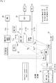
Fig. 1 , a system according to this exemplary embodiment includes a core network (3GPP network), one ormore MTC devices 10 which connect to the core network through a RAN (Radio Access Network), and anSCS 30 and anSME 40, each of which is placed outside the core network and serves as a transmission source of a trigger message. - Among them, each
MTC device 10 is a UE for MTC communication with the core network via the Um/Uu/LTE-Uu interface. The UE can host one or multiple MTC Applications. The corresponding MTC Applications in the external network are hosted on one or multiple ASs (Application Servers). - Further, the
SCS 30 and theSME 40 connect to the core network to communicate with theMTC device 10. - Furthermore, the core network includes an MTC-
IWF 21, anHSS 22, and GGSN/ P-GW 23 in the HPLMN (Home Public Land Mobile Network), and includes MME/ SGSN/MSC 24 and an S-GW 25 in the VPLMN (Visited PLMN). In the core network, each of the MTC-IWF 21 and the GGSN/P-GW 23 serves as a network node which receives a trigger message from its transmission source, each of the MME/SGSN/MSC 24 and the S-GW 25 serves as a network element which forwards the trigger message to theMTC device 10, and the HSS 22 (or e.g. HLR (Home Location Register)) serves as a server which provides various information to the network node. Typically, in a case of NAS message, the MTC-IWF 21 receives a trigger message from theSCS 30 via Tsp interface, and then forwards the trigger message to the MME via T5b interface. On the other hand, in a case of SMS message, the MTC-IWF 21 receives a trigger message from theSME 40 via T4 and Tsms interfaces (i.e. through SMS-SC/GMSC/IWMSC) or from theSCS 30 via Tsp interface, and then forwards the trigger message to the MME/SGSN/MSC 24 via T5b/T5a/T5c interface. Thus, the trigger message can be routed by the MME/SGSN/MSC 24 to theMTC device 10. TheHSS 22 stores MTC device capabilities and serving node information which will be described later, and notifies them to the MTC-IWF 21 via S6m interface. The GGSN/ P-GW 23 receives a trigger message from theSCS 30 or directly from the AS via Gi/ SGi interface, and then forwards the trigger message to the SGSN or the S-GW 25 through user plane, so that the trigger message can be also routed to theMTC device 10. - Next, operation examples of this exemplary embodiment will be described in detail with reference to
Fig. 2 . - In this exemplary embodiment, assume that the trigger source (i.e.
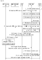
SCS 30 or SME 40) is properly authenticated to the network (Step S1). Mutual authentication between theMTC device 10 and the network is also performed. -
- 1) MTC-
IWF 21 downloads UE capabilities fromHSS 22 via interface S6m (Step S2). This can be a new message or the same message that MTC-IWF 21 retrieves UE's serving node information fromHSS 22. The UE capabilities can include, for example, information on which communication system (e.g. SAE (System Architecture Evolution)/LTE or 3G) theMTC device 10 supports. Preferably, as will be described in the following (2), the UE capabilities may include information as to whether or not theMTC device 10 supports IMS. On the other hand, the serving node information includes usage rates of the MME/SGSN/MSC 24. Additionally, routing information can be downloaded from theHSS 22 or the HLR. Data of routing information, serving node information can be pushed or downloaded from HSS/HLR and saved locally in SMSC/SMS-GMSC.
The downloading can happen when:- (A) MTC-
IWF 21 receives the first trigger; or - (B)
MTC device 10 is attached to the network andHSS 22 pushes the information to MTC-IWF 21.
- (A) MTC-
- 2) MTC-
IWF 21 stores the UE capabilities and serving node information locally, for a given period (Step S3). - 3)
HSS 22 or MTC-IWF 21 creates a priority list of MTC device trigger delivery route, with an expiry timer (Step S4). The priority could be simply a random selection, or decided by operator policy of network usage, or based on the serving node information and UE capabilities. Taking as an example the case where the serving node information includes the usage rates, priority list includes records in which the MME/ SGSN/MSC 24 are stored in association with their respective usage rates. Further, in the case where the list is created by theHSS 22, the MTC-IWF 21 downloads the list from theHSS 22. The downloading and/or creation are performed before the MTC-IWF 21 receives the trigger from theSCS 30. Note that the list should be removed if MTC-IWF 21 is informed theMTC device 10 is detached or when it is expired. - 4) MTC-
IWF 21 receives the trigger from the SCS 30 (Step S5). - 5) MTC-
IWF 21 performs authorization toSCS 30, to see whether it can send trigger message. - 6) MTC-
IWF 21 checks security context at a given network element, e.g. MME (Steps S6 and S7), which can be done by:- (A) Pinging given network element for information or by analyzing the information received from the HSS; or
- (B) Check with the information that provided by
HSS 22 when MTC-IWF 21 downloaded the serving node information, or pushed fromHSS 22 e.g. when UE changed its location.
- 7) If MME responds that it has no valid security context for the UE, MTC-
IWF 21 will send the trigger message to the next serving node in the priority list, e.g. SGSN (Steps S8 and S9). Then, SGSN forwards the trigger message to MTC device 10 (Step S10). MTC-IWF 21 should ensure that it does not choose the same route, by marking the failed path invalid. Thus, it is possible to prevent the trigger message from being redundantly re-forwarded through the failed path, so that the trigger message can more rapidly reach theMTC device 10. The route can be valid if MTC-IWF 21 receives information fromHSS 22 or MME that security context is established.
Thus, in this exemplary embodiment, it is possible to ensure that the trigger message can securely reach theMTC device 10, by deciding the network element which should transfer the trigger message based on the list. In the case where the MTC-IWF 21 creates the list, it is possible to rapidly select the valid path. This is because that the MTC-IWF 21 operates as an entrance into the core network.
Further, in the case where the list includes records in which the MME/SGSN/MSC 24 are stored in association with their respective usage rates, the MTC-IWF 21 can select the MME/SGSN/MSC 24 in ascending order of usage rate. Therefore, it is possible to reduce congestion of the core network. - 8) UE (MTC device 10) checks validity of the message carrying the trigger (this follows the current 3GPP specification security requirements) (Step S11).
- 9) If message is not validated correctly then
MTC device 10 discards the trigger message (Step S12) and sends a Reject message to MTC-IWF 21 indicating the reject cause (e.g. no proper security protection) (Step S13), otherwise accepts the trigger. - 10) After received the Reject message, MTC-
IWF 21 can do as follows:- (A) Choose the next path which is not marked as invalid from propriety list, and then forward the trigger through the chosen path (Step S14);
- (B) When there is no any control plane path available, MTC-
IWF 21 can forward the Reject message toSCS 30 such thatSCS 30 can send the trigger through user plane (Steps S15 and S16); - (C) Request MME to initiate AKA (Authentication and Key Agreement) and SMC (Short Message Control) procedure to establish security context such that it can forward the trigger message.
- Thus, in this exemplary embodiment, it is also possible to prevent the trigger message from being redundantly re-forwarded by use of the Reject message. Therefore, it is possible to reduce congestion of the core network and battery consumption of the
MTC device 10. For example, it can be ensured that an emergent trigger message or the like reaches theMTC device 10. - Although the illustration is omitted, with respect to user plane, the GGSN/P-
GW 23 performs similar processing with that of the MTC-IWF 21. Specifically, the GGSN/ P-GW 23 receives from the MTC device 10 a Reject message with a cause indicating there was no proper user plane confidentiality protection, finds another path to deliver the trigger. For example, if a path via the SGSN is not protected, the GGSN/P-GW 23 chooses a protected path via the S-GW 25 to forward the trigger message. - When the trigger message is sent as SMS, MTC devices which do not support IMS should also be considered. An SMS trigger message carried in NAS message to a MTC device which does not support IMS, CSFB may be initiated such that MME will forward the message to MSC. This will cause unnecessary traffic and delay the trigger delivery.
- In order to avoid them, the operation of this exemplary embodiment is performed as follows.
- 1) MTC-
IWF 21 can download MTC device capability of support IMS fromHSS 22 as described in (1). When an SMS trigger is to be forwarded, MTC-IWF 21 should check the local stored information to see whetherMTC device 10 supports IMS or not. - 2) If the
MTC device 10 does not support IMS, MTC-IWF 21 should forward the trigger directly to MSC, not MME. - In this way, the SMS trigger message is directly forwarded to the MMC not through the MME. Therefore, it is possible to avoid causing unnecessary traffic from the MME to the MSC, and thus to prevent the SMS trigger message from being delayed due to the redundant routing through both of the MME and the MSC.
- As shown in
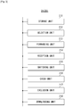
Fig. 3 , the MTC-IWF 21 includes at least a part or all of astorage unit 211, aselection unit 212, aforwarding unit 213, areception unit 214, aswitching unit 215, acheck unit 216, anexclusion unit 217, and adownloading unit 218. Theseunits 211 to 218 are mutually connected with each other through a bus or the like. Thestorage unit 211 stores the priority list. Theselection unit 212 selects one of the MME/ SGSN/MSC 24 based on the priority list. Theforwarding unit 213 forwards the trigger message to theMTC device 10 through the selected one of the MME/SGSN/MSC 24. Thereception unit 214 receives the trigger message from theSCS 30 or theSME 40, and receives the Reject message from theMTC device 10 through the selected one of the MME/SGSN/MSC 24. Theswitching unit 215 causes theforwarding unit 213 to forward the trigger message through a different one of the MME/SGSN/MSC 24, when the Reject message is received by thereception unit 214. Thecheck unit 216 checks whether or not the selected one of the MME/SGSN/MSC 24 can securely forward the trigger message to theMTC device 10. Theexclusion unit 217 instructs theforwarding unit 213 to exclude the selected one of the MME/SGSN/MSC 24 upon the subsequent forwarding, when thecheck unit 216 determines that the selected one of the MME/ SGSN/MSC 24 cannot securely forward the trigger message. The downloadingunit 218 can download from theHSS 22 the priority list to be stored in thestorage unit 211. Further, the downloadingunit 218 downloads the MTC device capability from theHSS 22. When the MTC device capability indicates that theMTC device 10 does not support IMS, theforwarding unit 213 forwards the trigger message directly to the MSC. - These
units 211 to 218 can be configured by, for example, transceivers which respectively conduct communication with theHSS 22, the MME/SGSN/MSC 24, theSCS 30 and theSME 40, and a controller which controls these transceivers to execute the processes shown at Steps S1 to S9 and S13 to S15 inFig. 2 or processes equivalent thereto. The GGSN/P-GW 23 can be also configured as with the MTC-IWF 21, except conducting communication with the SGSN, the S-GW 25, theSCS 30 and the AS through the user plane. - Further, as shown in
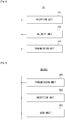
Fig. 4 , theMTC device 10 includes at least areception unit 101, avalidity unit 102, and atransmission unit 103. Theseunits 101 to 103 are mutually connected with each other thorough a bus or the like. Thereception unit 102 receives the trigger message from the core network. Thevalidity unit 102 validates the trigger message. Thetransmission unit 103 transmits the Reject message to the core network, when the trigger message is not validated by thevalidity unit 102. Theseunits 101 to 103 can be configured by, for example, a transceiver which wirelessly conducts communication with the core network through the RAN, and a controller which controls this transceiver to execute the processes shown at Steps S10 to S13 and S16 inFig. 2 or processes equivalent thereto. - Furthermore, as shown in
Fig. 5 , theSCS 30 includes at least atransmission unit 301, areception unit 302, and asend unit 303. Theseunits 301 to 303 are mutually connected with each other thorough a bus or the like. Thetransmission unit 301 transmits the trigger message to the core network through control plane (i.e. transmits the trigger message to the MTC-IWF 21 via Tsp interface). Thereception unit 302 receives the Reject message from the MTC-IWF 21. Thesend unit 303 sends the trigger message through user plane (i.e. sends the trigger message to the GGSN/P-GW 23 via Gi/SGi interface), when the Reject message is received by thereception unit 302. Theseunits 301 to 303 can be configured by, for example, transceivers which respectively conduct communication with the MTC-IWF 21 and the GGSN/P-GW 23, and a controller which controls these transceivers to execute the processes shown at Steps S1, S5, S15 and S16 inFig. 2 or processes equivalent thereto. TheSME 40 can be also configured as with theSCS 30, except transmitting the trigger message to the MSC-IWF 21 via the SMS-SC/GMSC/IWMSC. - Note that the present invention is not limited to the above-mentioned exemplary embodiment, and it is obvious that various modifications can be made by those of ordinary skill in the art based on the recitation of the claims.
- For example, the MTC-
IWF 21 or the GGSN/P-GW 23 may transfer the trigger message through a different network element, when a response to the trigger message is not received within a predetermined period of time. Specifically, thereception unit 214 receives the response from theMTC device 10. If the response is not received by thereception unit 214 within the period of time, theswitching unit 215 causes theforwarding unit 213 to forward the trigger message through a network element different from the selected network element. Note that the period of time can be measured by use of a timer, a counter or the like. Thus, it can be also ensured that the trigger message reaches theMTC device 10. In this case, it may not be required for theMTC device 10 to sends the Reject message, so that modification to theMTC device 10 can be reduced compared with the above-mentioned exemplary embodiment. - The whole or part of the exemplary embodiment disclosed above can be described as, but not limited to, the following supplementary notes.
- MTC-IWF downloads (requesting or being pushed) MTC device capabilities from HSS via interface S6m including for example if MTC device supports IMS. This can be a new message or a new field in the message which MTC-IWF retrieves MTC device serving node information.
- MTC device trigger delivery route priority list. This list is created based on the operator policy of network usage and/or by UE capability. The list can be created in HSS then pushed to MTC-IWF, or created by MTC-IWF after it downloaded the necessary information from HSS. The list can be stored in MTC-IWF locally.
- If a MME is the serving node, MTC-IWF checks with MME to see if it has valid NAS security context. When MME does not have valid security context, MTC-IWF should forward the trigger to other entities like SGSN/MSC according to the delivery route priority.
- When MTC device receives a trigger embedded in an unprotected NAS or user plane message, it sends a Trigger Reject message with cause indication to network node: MTC-IWF or GGSN/P-GW.
- MTC-IWF, which receives a reject message with a cause indicating there was no proper NAS protection, finds another path to deliver the trigger. When all the control plane paths are not available, MTC-IWF can initiate AKA and SMC procedure. It also can forward the Reject message to SCS, such that SCS can send the trigger message via user plane.
- GGSN/P-GW which receives a reject message with a cause indicating there was no proper user plane confidentiality protection, finds another path to deliver the trigger.
- There are two issues discussed in this document.
- First, SA2 TS 23.682 considers roaming in the architecture. In this case, the visited network may not be trusted by the MTC device and the triggers forwarded from such network should not be trusted and taken as valid either.
- Thus MTC device should:
- verify if the MTC-IWF it communicates with is authorized.
- be able to verify if the trigger is from a authorized MTC-IWF. If it is from an invalid MTC-IWF, MTC device should inform MME such that MME will suspend the communication with MTC-IWF and may have a further action.
- Second, when the MTC device receives a trigger without NAS integrity protection, the MTC device (as described in TR 33.868) "could discard the trigger or alternatively look deeper into the trigger if end-to-end protection was applied".
- A few things are concerned:
- The trigger cannot be received and MTC server or MTC user has no knowledge about the discard.
- It wastes network traffic and MTC device's battery, that if MME sends a trigger which will not be received.
- In order to solve the above described issue:
- MME should not send the trigger without protection in the first place
- If such trigger is received, MTC device should send Reject message to MME/ MTC-IWF/SCS with a cause of reject such that network can act accordingly:
- MME can Initiate AKA procedure to establish security context
- MTC-IWF can send the trigger from another path (i.e. via another network node), for example, SGSN. This can depend on operator policy and/or MTC device capabilities.
- Based on the discussion above, we propose to have the following change to TR 33.868.
- The main Device triggering mechanisms currently being considered in SA2 TR 23.888 [10] are triggering via NAS signalling (e.g. a new information element in an existing NAS message or a new NAS message) and triggering via SMS. The SMS trigger may possibly also be sent from the network to the MTC Device using NAS as a transport. In this case, current NAS security mechanisms can be used to solve the security issue. After NAS SMC, NAS security is activated. All NAS signaling messages should be integrity-protected according to TS 33.401 [13], and therefore current LTE security mechanisms ensure that the trigger indication is not tampered with. In this case the SMS trigger will also benefit from the integrity protection of NAS signalling in LTE.
- Source verification needs to be considered which in this context is understood to mean that the MTC Device can verify that the source of the trigger is a valid MTC server. This could be achieved in the following way.
- MTC Device trusts the 3GPP network sending the NAS integrity protected trigger. In this case the MTC Device could be configured with identities of trusted 3GPP networks. (Somewhat analogically as trusted non3GPP access networks can be configured in the UE in TS 33.402.) In this context trusted 3GPP network would mean networks which have a secured interface from the MTC server to the 3GPP network, and which are trusted to ensure that only trigger indications received from authorized MTC Servers will lead to triggering of MTC Devices "belonging" to that MTC server.
- The network may not be trusted for example when MTC device is roaming in the visited network, or when there is a strict security requirement for MTC. The MTC device should verify if the trigger is forwarded from a valid MTC-IWF.
- When the MTC Device then receives a NAS integrity protected trigger, it can, after verifying NAS integrity protection, verify the 3GPP network in the sense as described above. If both can be verified, the trigger can be accepted.
- MME should not send the trigger in a NAS message without integrity protection. If there is no NAS integrity protection of the trigger or if the 3GPP network is not trusted, the MTC Device could discard the trigger and send a Reject message to MME and MTC-IWF with a proper cause or alternatively look deeper into the trigger if end to-end protection was applied.
- When MME receives a reject response from MTC device with a cause indicating no integrity protection or integrity check failure, MME can
- Initiate 3GPP AKA procedure towards MTC device so that when there is security context shared between them MME can forward the trigger;
- Or forward the reject message to MTC-IWF, so that MTC-IWF can choose another route to send the trigger.
- This application is based upon and claims the benefit of priority from Japanese patent application No.
2012-147982, filed on June 29, 2012 2012-209393, filed on September 24, 2012 -
- 10 MTC DEVICE
- 21 MTC-IWF
- 22 HSS
- 23 GGSN/P-GW
- 24 MME/SGSN/MSC
- 25 S-GW
- 30 SCS
- 40 SME
- 101, 214, 302 RECEPTION UNIT
- 102 VALIDITY UNIT
- 103, 301 TRANSMISSION UNIT
- 211 STORAGE UNIT
- 212 SELECTION UNIT
- 213 FORWARDING UNIT
- 215 SWITCHING UNIT
- 216 CHECK UNIT
- 217 EXCLUSION UNIT
- 218 DOWNLOADING UNIT
- 303 SEND UNIT
Claims (8)
- A Machine Type Communication-Interworking Function, MTC-IWF, (21) in a mobile communication network including: a User Equipment, UE (10); a serving node (24) that is at least one of a Mobility Management Entity, MME, a Serving GPRS Support Node, SGSN, and a Mobile Switching Center, MSC; a Home Subscriber Server, HSS, (22) or a Home Location Register, HLR; and a Services Capability Server, SCS, (30), the MTC-IWF (21) comprising:means (214) for receiving route information on device trigger delivery including information on the serving node (24) from the HSS (22) or the HLR;characterised by means for prioritising the serving node (24) based on the information;means (212) for selecting the prioritised serving node (24) based on the route information; andmeans for delivering a trigger message from the SCS (30) to the UE (10) via the selected serving node (24).
- The Machine Type Communication-Interworking Function according to Claim 1, further comprising means (214) for receiving a failure message with cause indicating the failure if the device trigger delivery fails, and means for sending the failure message to the SCS (30).
- The Machine Type Communication-Interworking Function according to Claim 1, further comprising means (214) for receiving the trigger message for a Short Message Service, SMS, from a Short Message Service-Switching Center/Gateway Mobile Switching Center/Inter Working Mobile Switching Center, SMS-SC/GMSC/IWMSC.
- The Machine Type Communication-Interworking Function according to Claim 1, further comprising means (212) for re-selecting the prioritised serving node (24) based on the route information if the device trigger delivery fails.
- A method of controlling a Machine Type Communication-Interworking Function, MTC-IWF, (21) in a mobile communication network including: a User Equipment, UE (10); a serving node (24) that is at least one of a Mobility Management Entity, MME, a Serving GPRS Support Node, SGSN, and a Mobile Switching Center, MSC; a Home Subscriber Server, HSS, (22) or a Home Location Register, HLR; and a Services Capability Server, SCS, (30), the method comprising:receiving (S2) route information on device trigger delivery including information on the serving node (24) from the HSS (22) or the HLR;characterized by prioritising (S4) the serving node (24) based on the information;selecting (S6) the prioritised serving node (24) based on the route information; anddelivering (S9) a trigger message from the SCS (30) to the UE (10) via the selected serving node (24).
- The method according to Claim 5, further comprising receiving (S13) a failure message with cause indicating the failure if the device trigger delivery fails, and sending (S15) the failure message to the SCS (30).
- The method according to Claim 5, wherein the MTC-IWF (21) receives the trigger message for Short Message Service, SMS, from a Short Message Service-Switching Center/Gateway Mobile Switching Center/Inter Working Mobile Switching Center, SMS-SC/GMSC/IWMSC.
- The method according to Claim 5, further comprising re-selecting the prioritised serving node (24) based on the route information if the device trigger delivery fails.
Applications Claiming Priority (4)
| Application Number | Priority Date | Filing Date | Title |
|---|---|---|---|
| JP2012147982 | 2012-06-29 | ||
| JP2012209393 | 2012-09-24 | ||
| EP13725215.1A EP2868121A1 (en) | 2012-06-29 | 2013-04-23 | Optimization of mtc device trigger delivery |
| PCT/JP2013/002757 WO2014002355A1 (en) | 2012-06-29 | 2013-04-23 | Optimization of mtc device trigger delivery |
Related Parent Applications (1)
| Application Number | Title | Priority Date | Filing Date |
|---|---|---|---|
| EP13725215.1A Division EP2868121A1 (en) | 2012-06-29 | 2013-04-23 | Optimization of mtc device trigger delivery |
Publications (2)
| Publication Number | Publication Date |
|---|---|
| EP3396986A1 EP3396986A1 (en) | 2018-10-31 |
| EP3396986B1 true EP3396986B1 (en) | 2020-03-25 |
Family
ID=48521383
Family Applications (2)
| Application Number | Title | Priority Date | Filing Date |
|---|---|---|---|
| EP13725215.1A Withdrawn EP2868121A1 (en) | 2012-06-29 | 2013-04-23 | Optimization of mtc device trigger delivery |
| EP18178840.7A Active EP3396986B1 (en) | 2012-06-29 | 2013-04-23 | Optimization of mtc device trigger delivery |
Family Applications Before (1)
| Application Number | Title | Priority Date | Filing Date |
|---|---|---|---|
| EP13725215.1A Withdrawn EP2868121A1 (en) | 2012-06-29 | 2013-04-23 | Optimization of mtc device trigger delivery |
Country Status (8)
| Country | Link |
|---|---|
| US (4) | US20150189460A1 (en) |
| EP (2) | EP2868121A1 (en) |
| JP (1) | JP5994869B2 (en) |
| KR (3) | KR20150022885A (en) |
| CN (2) | CN104412620A (en) |
| BR (1) | BR112014032565A2 (en) |
| IN (1) | IN2014DN10451A (en) |
| WO (1) | WO2014002355A1 (en) |
Families Citing this family (10)
| Publication number | Priority date | Publication date | Assignee | Title |
|---|---|---|---|---|
| IN2014DN10451A (en) * | 2012-06-29 | 2015-08-21 | Nec Corp | |
| CN104768137B (en) | 2014-01-08 | 2019-03-12 | 阿尔卡特朗讯 | A kind of transmission method and device of the triggering report for MTC |
| US10129689B2 (en) | 2015-11-02 | 2018-11-13 | Definition Networks, Inc. | Systems and methods for machine-type communication |
| WO2017095809A1 (en) * | 2015-11-30 | 2017-06-08 | Intel Corporation | Mobile-terminated packet transmission |
| US10219198B2 (en) | 2016-05-24 | 2019-02-26 | At&T Intellectual Property I, L.P. | System and method for short message delivery in a mobility network |
| US20170013651A1 (en) * | 2016-09-22 | 2017-01-12 | Mediatek Singapore Pte. Ltd. | NAS Security And Handling Of Multiple Initial NAS Messages |
| EP3524033A1 (en) | 2016-10-07 | 2019-08-14 | Nokia Solutions and Networks Oy | Stateless network architecture |
| US10075827B1 (en) | 2017-03-07 | 2018-09-11 | At&T Intellectual Proprety I, L.P. | System and method for machine to machine subscriber information and retrieval protection |
| US10448243B2 (en) * | 2017-03-23 | 2019-10-15 | Cisco Technology, Inc. | System and method to facilitate device triggering for non-internet protocol data delivery in a network environment |
| EP3442202B1 (en) | 2017-06-19 | 2020-09-16 | Huawei Technologies Co., Ltd. | Registration and session establishment methods, terminal, and amf entity |
Family Cites Families (30)
| Publication number | Priority date | Publication date | Assignee | Title |
|---|---|---|---|---|
| US7106698B1 (en) * | 1998-09-16 | 2006-09-12 | Cisco Technology, Inc. | System for triggering the control plane in an asynchronous connection-oriented transmission network |
| JP4477884B2 (en) * | 2004-01-14 | 2010-06-09 | パナソニック株式会社 | Network control device, communication terminal, communication connection method, connection registration method to network |
| WO2006131070A1 (en) * | 2005-06-07 | 2006-12-14 | Huawei Technologies Co., Ltd. | A method for achieving voice service based on the service trigger, the route control method and the system therefor |
| JP2009130657A (en) * | 2007-11-26 | 2009-06-11 | Fujitsu Ltd | Load distributing method of mobile communication system, and mobile communication system |
| US7931784B2 (en) * | 2008-04-30 | 2011-04-26 | Xyleco, Inc. | Processing biomass and petroleum containing materials |
| US8511391B2 (en) | 2009-07-22 | 2013-08-20 | Baker Hughes Incorporated | Apparatus and method for coupling conduit segments |
| CN102065406B (en) | 2009-11-12 | 2014-04-09 | 中兴通讯股份有限公司 | Implementation method for local switch of local call |
| WO2011099774A2 (en) * | 2010-02-10 | 2011-08-18 | Lg Electronics Inc. | Method of exchanging sms data in a wireless communications system |
| US20110231654A1 (en) * | 2010-03-16 | 2011-09-22 | Gurudas Somadder | Method, system and apparatus providing secure infrastructure |
| US9036481B1 (en) * | 2010-05-05 | 2015-05-19 | Marvell International Ltd. | Method and apparatus for adaptive packet load balancing |
| CN102404825B (en) * | 2010-09-19 | 2016-03-30 | 中兴通讯股份有限公司 | A kind of method and system by NAS signaling triggering terminal |
| JP5682208B2 (en) * | 2010-10-04 | 2015-03-11 | ソニー株式会社 | COMMUNICATION DEVICE, COMMUNICATION CONTROL METHOD, AND COMMUNICATION SYSTEM |
| CN102457839B (en) * | 2010-10-29 | 2015-04-01 | 中兴通讯股份有限公司 | Method and device for triggering service of machine-type communication terminal |
| CN102148863A (en) * | 2011-01-27 | 2011-08-10 | 华为技术有限公司 | Method and device for delivering M2M (machine to machine) service messages |
| KR20120094454A (en) * | 2011-02-16 | 2012-08-24 | 에이치티씨 코포레이션 | Service networks and methods for handling machine type communication device triggering |
| GB2476415B (en) * | 2011-03-23 | 2011-11-16 | Renesas Mobile Corp | Method and apparatus for facilitating machine-type communication |
| US20120252481A1 (en) * | 2011-04-01 | 2012-10-04 | Cisco Technology, Inc. | Machine to machine communication in a communication network |
| US9820335B2 (en) * | 2011-04-01 | 2017-11-14 | Interdigital Patent Holdings, Inc. | System and method for sharing a common PDP context |
| WO2012135582A1 (en) * | 2011-04-01 | 2012-10-04 | Interdigital Patent Holdings, Inc. | Network initiated triggering of an offline device |
| US9113355B2 (en) * | 2011-04-07 | 2015-08-18 | Htc Corporation | Method of handling signaling and data transmission for machine-type communication |
| CN103597863A (en) * | 2011-04-14 | 2014-02-19 | 中兴通讯(美国)公司 | Methods and apparatus for determining address of a machine type communication device in a wireless network |
| US9313747B2 (en) * | 2011-07-01 | 2016-04-12 | Intel Corporation | Structured codebook for uniform circular array (UCA) |
| US9291317B2 (en) * | 2011-07-29 | 2016-03-22 | Cooper Technologies Company | Channel-type connection structure for a lighting system |
| CN104025475B (en) * | 2011-10-03 | 2018-04-13 | 英特尔公司 | Device is to device (D2D) communication mechanism |
| US9083983B2 (en) | 2011-10-04 | 2015-07-14 | Qualcomm Incorporated | Motion vector predictor candidate clipping removal for video coding |
| SG11201401209SA (en) * | 2011-10-31 | 2014-07-30 | Ericsson Telefon Ab L M | Securing data communications in a communications network |
| EP2774451B1 (en) * | 2011-11-04 | 2017-08-30 | Intel Corporation | Small data techniques and configurations in a wireless communication network |
| WO2013070051A1 (en) * | 2011-11-13 | 2013-05-16 | 엘지전자 주식회사 | Method and device for triggering machine-type communication mtc in wireless communication system |
| CN105306183B (en) * | 2011-12-02 | 2019-02-05 | 电信科学技术研究院 | The delivery confirmation method and apparatus of MTC Device triggering message |
| IN2014DN10451A (en) * | 2012-06-29 | 2015-08-21 | Nec Corp |
-
2013
- 2013-04-23 IN IN10451DEN2014 patent/IN2014DN10451A/en unknown
- 2013-04-23 CN CN201380034378.7A patent/CN104412620A/en active Pending
- 2013-04-23 EP EP13725215.1A patent/EP2868121A1/en not_active Withdrawn
- 2013-04-23 US US14/409,968 patent/US20150189460A1/en not_active Abandoned
- 2013-04-23 KR KR1020147036102A patent/KR20150022885A/en active IP Right Grant
- 2013-04-23 JP JP2014558698A patent/JP5994869B2/en active Active
- 2013-04-23 BR BR112014032565A patent/BR112014032565A2/en not_active IP Right Cessation
- 2013-04-23 KR KR1020167033385A patent/KR101725030B1/en active IP Right Grant
- 2013-04-23 EP EP18178840.7A patent/EP3396986B1/en active Active
- 2013-04-23 KR KR1020177008916A patent/KR101753030B1/en active IP Right Grant
- 2013-04-23 CN CN201710951021.5A patent/CN107682842B/en active Active
- 2013-04-23 WO PCT/JP2013/002757 patent/WO2014002355A1/en active Application Filing
-
2016
- 2016-11-23 US US15/360,138 patent/US10447576B2/en active Active
-
2019
- 2019-08-08 US US16/535,626 patent/US11296976B2/en active Active
-
2021
- 2021-12-09 US US17/546,216 patent/US11863425B2/en active Active
Non-Patent Citations (1)
| Title |
|---|
| None * |
Also Published As
| Publication number | Publication date |
|---|---|
| US20150189460A1 (en) | 2015-07-02 |
| US10447576B2 (en) | 2019-10-15 |
| EP2868121A1 (en) | 2015-05-06 |
| IN2014DN10451A (en) | 2015-08-21 |
| JP2015525485A (en) | 2015-09-03 |
| EP3396986A1 (en) | 2018-10-31 |
| US11296976B2 (en) | 2022-04-05 |
| KR20170039770A (en) | 2017-04-11 |
| US20170078832A1 (en) | 2017-03-16 |
| KR20160141869A (en) | 2016-12-09 |
| WO2014002355A1 (en) | 2014-01-03 |
| BR112014032565A2 (en) | 2017-06-27 |
| KR101753030B1 (en) | 2017-07-03 |
| JP5994869B2 (en) | 2016-09-21 |
| US20220103459A1 (en) | 2022-03-31 |
| KR20150022885A (en) | 2015-03-04 |
| CN104412620A (en) | 2015-03-11 |
| KR101725030B1 (en) | 2017-04-07 |
| US20190363972A1 (en) | 2019-11-28 |
| CN107682842A (en) | 2018-02-09 |
| US11863425B2 (en) | 2024-01-02 |
| CN107682842B (en) | 2020-10-16 |
Similar Documents
| Publication | Publication Date | Title |
|---|---|---|
| US11863425B2 (en) | Optimization of MTC device trigger delivery | |
| US11700667B2 (en) | Control plane cellular internet-of-things (IOT) optimization indication | |
| TWI738703B (en) | Enhancements to nas protocol to transmit small data over signaling plane | |
| EP3300408B1 (en) | Secure method for mtc device triggering | |
| JP6093852B2 (en) | Service capability server (SCS) terminated short message service (SMS) system and method | |
| CN112567777B (en) | Techniques in an evolved packet core for restricted home carrier service access | |
| JP5871733B2 (en) | Triggering with time indicator | |
| WO2013081412A1 (en) | Method and device for supporting mtc trigger of serving node in wireless communication system | |
| US11601790B2 (en) | Apparatus, system and method for mobile communication | |
| WO2015028048A1 (en) | Method and apparatus |
Legal Events
| Date | Code | Title | Description |
|---|---|---|---|
| PUAI | Public reference made under article 153(3) epc to a published international application that has entered the european phase |
Free format text: ORIGINAL CODE: 0009012 |
|
| STAA | Information on the status of an ep patent application or granted ep patent |
Free format text: STATUS: REQUEST FOR EXAMINATION WAS MADE |
|
| 17P | Request for examination filed |
Effective date: 20180620 |
|
| AC | Divisional application: reference to earlier application |
Ref document number: 2868121 Country of ref document: EP Kind code of ref document: P |
|
| AK | Designated contracting states |
Kind code of ref document: A1 Designated state(s): AL AT BE BG CH CY CZ DE DK EE ES FI FR GB GR HR HU IE IS IT LI LT LU LV MC MK MT NL NO PL PT RO RS SE SI SK SM TR |
|
| RBV | Designated contracting states (corrected) |
Designated state(s): AL AT BE BG CH CY CZ DE DK EE ES FI FR GB GR HR HU IE IS IT LI LT LU LV MC MK MT NL NO PL PT RO RS SE SI SK SM TR |
|
| GRAP | Despatch of communication of intention to grant a patent |
Free format text: ORIGINAL CODE: EPIDOSNIGR1 |
|
| STAA | Information on the status of an ep patent application or granted ep patent |
Free format text: STATUS: GRANT OF PATENT IS INTENDED |
|
| RIC1 | Information provided on ipc code assigned before grant |
Ipc: H04W 4/70 20180101AFI20190920BHEP Ipc: H04W 52/02 20090101ALI20190920BHEP |
|
| INTG | Intention to grant announced |
Effective date: 20191016 |
|
| GRAS | Grant fee paid |
Free format text: ORIGINAL CODE: EPIDOSNIGR3 |
|
| GRAA | (expected) grant |
Free format text: ORIGINAL CODE: 0009210 |
|
| STAA | Information on the status of an ep patent application or granted ep patent |
Free format text: STATUS: THE PATENT HAS BEEN GRANTED |
|
| AC | Divisional application: reference to earlier application |
Ref document number: 2868121 Country of ref document: EP Kind code of ref document: P |
|
| AK | Designated contracting states |
Kind code of ref document: B1 Designated state(s): AL AT BE BG CH CY CZ DE DK EE ES FI FR GB GR HR HU IE IS IT LI LT LU LV MC MK MT NL NO PL PT RO RS SE SI SK SM TR |
|
| REG | Reference to a national code |
Ref country code: GB Ref legal event code: FG4D |
|
| REG | Reference to a national code |
Ref country code: AT Ref legal event code: REF Ref document number: 1249996 Country of ref document: AT Kind code of ref document: T Effective date: 20200415 Ref country code: IE Ref legal event code: FG4D |
|
| REG | Reference to a national code |
Ref country code: DE Ref legal event code: R096 Ref document number: 602013067343 Country of ref document: DE |
|
| PG25 | Lapsed in a contracting state [announced via postgrant information from national office to epo] |
Ref country code: FI Free format text: LAPSE BECAUSE OF FAILURE TO SUBMIT A TRANSLATION OF THE DESCRIPTION OR TO PAY THE FEE WITHIN THE PRESCRIBED TIME-LIMIT Effective date: 20200325 Ref country code: NO Free format text: LAPSE BECAUSE OF FAILURE TO SUBMIT A TRANSLATION OF THE DESCRIPTION OR TO PAY THE FEE WITHIN THE PRESCRIBED TIME-LIMIT Effective date: 20200625 Ref country code: RS Free format text: LAPSE BECAUSE OF FAILURE TO SUBMIT A TRANSLATION OF THE DESCRIPTION OR TO PAY THE FEE WITHIN THE PRESCRIBED TIME-LIMIT Effective date: 20200325 |
|
| PGFP | Annual fee paid to national office [announced via postgrant information from national office to epo] |
Ref country code: FR Payment date: 20200430 Year of fee payment: 8 |
|
| PG25 | Lapsed in a contracting state [announced via postgrant information from national office to epo] |
Ref country code: GR Free format text: LAPSE BECAUSE OF FAILURE TO SUBMIT A TRANSLATION OF THE DESCRIPTION OR TO PAY THE FEE WITHIN THE PRESCRIBED TIME-LIMIT Effective date: 20200626 Ref country code: HR Free format text: LAPSE BECAUSE OF FAILURE TO SUBMIT A TRANSLATION OF THE DESCRIPTION OR TO PAY THE FEE WITHIN THE PRESCRIBED TIME-LIMIT Effective date: 20200325 Ref country code: BG Free format text: LAPSE BECAUSE OF FAILURE TO SUBMIT A TRANSLATION OF THE DESCRIPTION OR TO PAY THE FEE WITHIN THE PRESCRIBED TIME-LIMIT Effective date: 20200625 Ref country code: SE Free format text: LAPSE BECAUSE OF FAILURE TO SUBMIT A TRANSLATION OF THE DESCRIPTION OR TO PAY THE FEE WITHIN THE PRESCRIBED TIME-LIMIT Effective date: 20200325 Ref country code: LV Free format text: LAPSE BECAUSE OF FAILURE TO SUBMIT A TRANSLATION OF THE DESCRIPTION OR TO PAY THE FEE WITHIN THE PRESCRIBED TIME-LIMIT Effective date: 20200325 |
|
| REG | Reference to a national code |
Ref country code: NL Ref legal event code: MP Effective date: 20200325 |
|
| REG | Reference to a national code |
Ref country code: LT Ref legal event code: MG4D |
|
| PG25 | Lapsed in a contracting state [announced via postgrant information from national office to epo] |
Ref country code: NL Free format text: LAPSE BECAUSE OF FAILURE TO SUBMIT A TRANSLATION OF THE DESCRIPTION OR TO PAY THE FEE WITHIN THE PRESCRIBED TIME-LIMIT Effective date: 20200325 |
|
| PG25 | Lapsed in a contracting state [announced via postgrant information from national office to epo] |
Ref country code: CZ Free format text: LAPSE BECAUSE OF FAILURE TO SUBMIT A TRANSLATION OF THE DESCRIPTION OR TO PAY THE FEE WITHIN THE PRESCRIBED TIME-LIMIT Effective date: 20200325 Ref country code: IS Free format text: LAPSE BECAUSE OF FAILURE TO SUBMIT A TRANSLATION OF THE DESCRIPTION OR TO PAY THE FEE WITHIN THE PRESCRIBED TIME-LIMIT Effective date: 20200725 Ref country code: SK Free format text: LAPSE BECAUSE OF FAILURE TO SUBMIT A TRANSLATION OF THE DESCRIPTION OR TO PAY THE FEE WITHIN THE PRESCRIBED TIME-LIMIT Effective date: 20200325 Ref country code: PT Free format text: LAPSE BECAUSE OF FAILURE TO SUBMIT A TRANSLATION OF THE DESCRIPTION OR TO PAY THE FEE WITHIN THE PRESCRIBED TIME-LIMIT Effective date: 20200818 Ref country code: LT Free format text: LAPSE BECAUSE OF FAILURE TO SUBMIT A TRANSLATION OF THE DESCRIPTION OR TO PAY THE FEE WITHIN THE PRESCRIBED TIME-LIMIT Effective date: 20200325 Ref country code: RO Free format text: LAPSE BECAUSE OF FAILURE TO SUBMIT A TRANSLATION OF THE DESCRIPTION OR TO PAY THE FEE WITHIN THE PRESCRIBED TIME-LIMIT Effective date: 20200325 Ref country code: EE Free format text: LAPSE BECAUSE OF FAILURE TO SUBMIT A TRANSLATION OF THE DESCRIPTION OR TO PAY THE FEE WITHIN THE PRESCRIBED TIME-LIMIT Effective date: 20200325 Ref country code: SM Free format text: LAPSE BECAUSE OF FAILURE TO SUBMIT A TRANSLATION OF THE DESCRIPTION OR TO PAY THE FEE WITHIN THE PRESCRIBED TIME-LIMIT Effective date: 20200325 |
|
| REG | Reference to a national code |
Ref country code: AT Ref legal event code: MK05 Ref document number: 1249996 Country of ref document: AT Kind code of ref document: T Effective date: 20200325 |
|
| REG | Reference to a national code |
Ref country code: CH Ref legal event code: PL |
|
| PG25 | Lapsed in a contracting state [announced via postgrant information from national office to epo] |
Ref country code: MC Free format text: LAPSE BECAUSE OF FAILURE TO SUBMIT A TRANSLATION OF THE DESCRIPTION OR TO PAY THE FEE WITHIN THE PRESCRIBED TIME-LIMIT Effective date: 20200325 |
|
| REG | Reference to a national code |
Ref country code: DE Ref legal event code: R097 Ref document number: 602013067343 Country of ref document: DE |
|
| PG25 | Lapsed in a contracting state [announced via postgrant information from national office to epo] |
Ref country code: LU Free format text: LAPSE BECAUSE OF NON-PAYMENT OF DUE FEES Effective date: 20200423 Ref country code: DK Free format text: LAPSE BECAUSE OF FAILURE TO SUBMIT A TRANSLATION OF THE DESCRIPTION OR TO PAY THE FEE WITHIN THE PRESCRIBED TIME-LIMIT Effective date: 20200325 Ref country code: CH Free format text: LAPSE BECAUSE OF NON-PAYMENT OF DUE FEES Effective date: 20200430 Ref country code: ES Free format text: LAPSE BECAUSE OF FAILURE TO SUBMIT A TRANSLATION OF THE DESCRIPTION OR TO PAY THE FEE WITHIN THE PRESCRIBED TIME-LIMIT Effective date: 20200325 Ref country code: LI Free format text: LAPSE BECAUSE OF NON-PAYMENT OF DUE FEES Effective date: 20200430 Ref country code: IT Free format text: LAPSE BECAUSE OF FAILURE TO SUBMIT A TRANSLATION OF THE DESCRIPTION OR TO PAY THE FEE WITHIN THE PRESCRIBED TIME-LIMIT Effective date: 20200325 Ref country code: AT Free format text: LAPSE BECAUSE OF FAILURE TO SUBMIT A TRANSLATION OF THE DESCRIPTION OR TO PAY THE FEE WITHIN THE PRESCRIBED TIME-LIMIT Effective date: 20200325 |
|
| REG | Reference to a national code |
Ref country code: BE Ref legal event code: MM Effective date: 20200430 |
|
| PLBE | No opposition filed within time limit |
Free format text: ORIGINAL CODE: 0009261 |
|
| STAA | Information on the status of an ep patent application or granted ep patent |
Free format text: STATUS: NO OPPOSITION FILED WITHIN TIME LIMIT |
|
| PG25 | Lapsed in a contracting state [announced via postgrant information from national office to epo] |
Ref country code: PL Free format text: LAPSE BECAUSE OF FAILURE TO SUBMIT A TRANSLATION OF THE DESCRIPTION OR TO PAY THE FEE WITHIN THE PRESCRIBED TIME-LIMIT Effective date: 20200325 Ref country code: BE Free format text: LAPSE BECAUSE OF NON-PAYMENT OF DUE FEES Effective date: 20200430 |
|
| 26N | No opposition filed |
Effective date: 20210112 |
|
| PG25 | Lapsed in a contracting state [announced via postgrant information from national office to epo] |
Ref country code: IE Free format text: LAPSE BECAUSE OF NON-PAYMENT OF DUE FEES Effective date: 20200423 |
|
| PG25 | Lapsed in a contracting state [announced via postgrant information from national office to epo] |
Ref country code: SI Free format text: LAPSE BECAUSE OF FAILURE TO SUBMIT A TRANSLATION OF THE DESCRIPTION OR TO PAY THE FEE WITHIN THE PRESCRIBED TIME-LIMIT Effective date: 20200325 |
|
| PG25 | Lapsed in a contracting state [announced via postgrant information from national office to epo] |
Ref country code: FR Free format text: LAPSE BECAUSE OF NON-PAYMENT OF DUE FEES Effective date: 20210430 |
|
| PG25 | Lapsed in a contracting state [announced via postgrant information from national office to epo] |
Ref country code: TR Free format text: LAPSE BECAUSE OF FAILURE TO SUBMIT A TRANSLATION OF THE DESCRIPTION OR TO PAY THE FEE WITHIN THE PRESCRIBED TIME-LIMIT Effective date: 20200325 Ref country code: MT Free format text: LAPSE BECAUSE OF FAILURE TO SUBMIT A TRANSLATION OF THE DESCRIPTION OR TO PAY THE FEE WITHIN THE PRESCRIBED TIME-LIMIT Effective date: 20200325 Ref country code: CY Free format text: LAPSE BECAUSE OF FAILURE TO SUBMIT A TRANSLATION OF THE DESCRIPTION OR TO PAY THE FEE WITHIN THE PRESCRIBED TIME-LIMIT Effective date: 20200325 |
|
| PG25 | Lapsed in a contracting state [announced via postgrant information from national office to epo] |
Ref country code: MK Free format text: LAPSE BECAUSE OF FAILURE TO SUBMIT A TRANSLATION OF THE DESCRIPTION OR TO PAY THE FEE WITHIN THE PRESCRIBED TIME-LIMIT Effective date: 20200325 Ref country code: AL Free format text: LAPSE BECAUSE OF FAILURE TO SUBMIT A TRANSLATION OF THE DESCRIPTION OR TO PAY THE FEE WITHIN THE PRESCRIBED TIME-LIMIT Effective date: 20200325 |
|
| PGFP | Annual fee paid to national office [announced via postgrant information from national office to epo] |
Ref country code: DE Payment date: 20230420 Year of fee payment: 11 |
|
| PGFP | Annual fee paid to national office [announced via postgrant information from national office to epo] |
Ref country code: GB Payment date: 20230419 Year of fee payment: 11 |