EP3396873A1 - Mobile communication device and method - Google Patents
Mobile communication device and method Download PDFInfo
- Publication number
- EP3396873A1 EP3396873A1 EP17203744.2A EP17203744A EP3396873A1 EP 3396873 A1 EP3396873 A1 EP 3396873A1 EP 17203744 A EP17203744 A EP 17203744A EP 3396873 A1 EP3396873 A1 EP 3396873A1
- Authority
- EP
- European Patent Office
- Prior art keywords
- mobile communication
- communication device
- channel
- digital
- signals
- Prior art date
- Legal status (The legal status is an assumption and is not a legal conclusion. Google has not performed a legal analysis and makes no representation as to the accuracy of the status listed.)
- Granted
Links
Images


Classifications
-
- H—ELECTRICITY
- H04—ELECTRIC COMMUNICATION TECHNIQUE
- H04B—TRANSMISSION
- H04B17/00—Monitoring; Testing
- H04B17/30—Monitoring; Testing of propagation channels
- H04B17/391—Modelling the propagation channel
-
- H—ELECTRICITY
- H04—ELECTRIC COMMUNICATION TECHNIQUE
- H04W—WIRELESS COMMUNICATION NETWORKS
- H04W24/00—Supervisory, monitoring or testing arrangements
- H04W24/06—Testing, supervising or monitoring using simulated traffic
-
- H—ELECTRICITY
- H04—ELECTRIC COMMUNICATION TECHNIQUE
- H04B—TRANSMISSION
- H04B1/00—Details of transmission systems, not covered by a single one of groups H04B3/00 - H04B13/00; Details of transmission systems not characterised by the medium used for transmission
- H04B1/38—Transceivers, i.e. devices in which transmitter and receiver form a structural unit and in which at least one part is used for functions of transmitting and receiving
- H04B1/40—Circuits
- H04B1/403—Circuits using the same oscillator for generating both the transmitter frequency and the receiver local oscillator frequency
- H04B1/406—Circuits using the same oscillator for generating both the transmitter frequency and the receiver local oscillator frequency with more than one transmission mode, e.g. analog and digital modes
-
- H—ELECTRICITY
- H04—ELECTRIC COMMUNICATION TECHNIQUE
- H04B—TRANSMISSION
- H04B17/00—Monitoring; Testing
- H04B17/30—Monitoring; Testing of propagation channels
- H04B17/309—Measuring or estimating channel quality parameters
-
- H—ELECTRICITY
- H04—ELECTRIC COMMUNICATION TECHNIQUE
- H04B—TRANSMISSION
- H04B17/00—Monitoring; Testing
- H04B17/30—Monitoring; Testing of propagation channels
- H04B17/391—Modelling the propagation channel
- H04B17/3912—Simulation models, e.g. distribution of spectral power density or received signal strength indicator [RSSI] for a given geographic region
-
- H—ELECTRICITY
- H04—ELECTRIC COMMUNICATION TECHNIQUE
- H04B—TRANSMISSION
- H04B17/00—Monitoring; Testing
- H04B17/10—Monitoring; Testing of transmitters
- H04B17/15—Performance testing
- H04B17/19—Self-testing arrangements
-
- H—ELECTRICITY
- H04—ELECTRIC COMMUNICATION TECHNIQUE
- H04B—TRANSMISSION
- H04B17/00—Monitoring; Testing
- H04B17/30—Monitoring; Testing of propagation channels
- H04B17/391—Modelling the propagation channel
- H04B17/3911—Fading models or fading generators
Definitions
- the present invention relates to a mobile communication device.
- the present invention further relates to a method for operating a mobile communication device.
- Modern communication systems increasingly use wireless communication between the single devices.
- During development, production or in the field of devices for such communication systems it is necessary to thoroughly test the wireless communication capabilities of the devices for compliance with communication standards and legal regulations and analyze different configurations of the wireless devices in the field.
- the problem addressed by the present invention is allowing simplified testing of mobile devices.
- the present invention solves this objective by a mobile communication device with the features of claim 1 and a method with the features of claim 15.
- the mobile communication device may e.g. be a smartphone or an internet-of-things wireless device or any other wireless device that communicates via the wireless communication channel.
- the wireless communication channel may comprise e.g. a specific frequency range in a frequency band that is specified for the communication system that the mobile communication device uses.
- the communication channels i.e. the respective frequency ranges, will be specified e.g. by a respective communication standard.
- the actual wireless communication channel that the mobile communication device uses for communication may e.g. be determined by a base station to which the communication device is connected.
- the communication interface may also be called the modem of the mobile communication device and manage the communication of the mobile communication device via the wireless communication channel.
- the communication interface therefore serves to convert e.g. digital voice or data signals into waveforms, i.e. analog signals, that may transmit the digital voice or data signals via the wireless communication channel. Further, the communication interface will convert received waveforms or analog signals into digital voice or data signals that may then be further processed in the mobile communication device.
- the channel simulation unit serves to modify properties of the wireless communication channel, such properties may refer to different aspects of the wireless communication channel like attenuations, reflections, Doppler shifts, range delays, fading and noise.
- the channel simulation unit may modify any of the above mentioned aspects individually or in combination.
- Waveform in this regard refers to a set of parameters for the wireless communication via the wireless communication channel, like e.g. the used frequencies, the type of modulation scheme that should be used or any other relevant parameters.
- the integrated channel simulation unit it is now possible to directly verify the behavior of such a waveform with the actual mobile communication device.
- An operator of a mobile device communication system may with this arrangement e.g. perform automated over-the-air configurations of the mobile communication devices and monitor the mobile communication devices for example with the same waveforms under different geographic circumstances, e.g. in a city or in mountains.
- the mobile communication devices can e.g. also be provided with different waveforms in the same geographic area.
- the results of such tests may then e.g. be provided by the mobile communication device via the communication interface to a central test server.
- the communication interface may comprise an analog-to-digital converter coupled to a signal input of the mobile communication device and a first signal processor for processing digital signals provided by the analog-to-digital converter.
- the signal input may e.g. comprise an antenna or antenna array of the mobile communication device.
- the analog-to-digital converter, ADC may be coupled to the signal input and convert the analog signals received by the signal input into digital signals that may then be further processed by the first signal processor.
- the first signal processor may be any type of processing device, like e.g. an AISC, a DSP, a FPGA or the like.
- the first signal processor may also be integrated into another processing unit of the mobile communication device as firmware or software functions.
- the channel simulation unit may be arranged between the signal input and the analog-to-digital converter.
- the channel simulation unit may be an individual or discrete unit that is provided in the mobile communication device in the analog part of the signal chain. It is understood that the channel simulation unit may comprise any necessary elements to process analog signals. Such elements may e.g. comprise any one of or a combination of input filters, ADCs, signal processors, DACs, and output filters.
- the channel simulation unit may be arranged between the analog-to-digital converter and the first signal processor.
- a pure digital channel simulation unit may be provided between the analog-to-digital converter and the first signal processor. This allows simplifying the channel simulation unit.
- the channel simulation unit may e.g. be provided as pure firmware or software function in a firmware or software that is executed by the first signal processor.
- the channel simulation unit may receive the digital data from the analog-to-digital converter, perform respective processing for introducing the channel simulation modifications, and forward the modified digital data to the first signal processor, i.e. the signal processing functions in the first signal processor.
- the communication interface may comprise a digital-to-analog converter coupled to a signal output of the mobile communication device for converting digital signals provided by a second signal processor into analog signals.
- the signal output may e.g. also comprise an antenna or antenna array of the mobile communication device. It is understood, that the signal output and the signal input may comprise the same antenna or antenna array.
- the digital-to-analog converter, DAC may be coupled to the second signal processor and convert the digital signals provided by the second signal processor into analog waveforms for transmission via the signal output.
- the second signal processor may be any type of processing device, like e.g. an AISC, a DSP, a FPGA or the like.
- the second signal processor may also be integrated into another processing unit of the mobile communication device as firmware or software functions. It is further understood that the first and the second signal processors may be integrally formed as a single device, firmware or software.
- the channel simulation unit may be arranged between the digital-to-analog converter and the signal output.
- the channel simulation unit may be an individual or discrete unit that is provided in the mobile communication device in the analog part of the signal chain. With such a channel simulation unit it is further possible to test at least part of the analog signal chain in the mobile communication device, especially the digital-to-analog converter of the communication interface, in addition to the digital signal chain in the mobile communication device.
- the channel simulation unit may be arranged between the digital-to-analog converter and the second signal processor.
- a pure digital channel simulation unit may be provided between the digital-to-analog converter and the second signal processor. This allows simplifying the channel simulation unit and providing the channel simulation unit e.g. as pure firmware or software function in a firmware or software that is executed by the second signal processor.
- the channel simulation unit may receive the digital data from the second signal processor, perform respective processing for introducing the channel simulation modifications, and forward the modified digital data to the digital-to-analog converter.
- the digital-to-analog converter will then forward respective analog data to the analog signal chain for wireless transmission, e.g. via an antenna or antenna array of the mobile communication device.
- the channel simulation unit may comprise a downstream section and an upstream section.
- the downstream section may refer to the channel simulation unit in conjunction with the analog-to-digital converter and the first signal processor.
- the upstream section may refer to the channel simulation unit in conjunction with the digital-to-analog converter and the second signal processor.
- the channel simulation unit may also be a single channel simulation unit for the downstream and the upstream.
- the channel simulation unit may comprise software and/or firmware and/or hardware elements.
- channel simulation unit comprises either firmware or software or hardware. It is however understood, that any combination of software and hardware is possible.
- the channel simulation unit i.e. single elements of the channel simulation unit, may in the downlink therefore be arranged between the signal input and the analog-to-digital converter as well as between the analog-to-digital converter and the first signal processor.
- the channel simulation unit i.e. its elements, may be provided between the digital-to-analog converter and the signal output as well as between the digital-to-analog converter and the second signal processor.
- the mobile communication device may comprise a controllable bypass device for controllably bypassing the channel simulation unit.
- the controllable bypass device may therefore e.g. be a hardware switching device that forwards signals around the channel simulation unit.
- the controllable bypass device may in addition or as an alternative also be a software or firmware switch.
- Such a software or firmware switch may cause certain channel simulation unit functions to be actively called in an active mode of the channel simulation unit. In an inactive mode of the channel simulation unit such software or firmware switches may cause the respective functions to be skipped.
- the channel simulation unit may comprise a signal processing unit for processing incoming signals for the communication interface and/or for processing outgoing signals from the communication interface.
- the signal processing unit may e.g. be a discrete unit like a DSP, e.g. with corresponding filters, ADCs, DACs and the like.
- the signal processing unit may also be a software or firmware in the first signal processor and/or second signal processor without dedicated analog circuitry for the signal processing unit.
- the channel simulation unit may comprise a memory for storing information about required or instructed modifications of the wireless communication channel.
- the memory may be a discrete memory or comprise variables in a memory of the communication interface.
- the stored information may e.g. specify the details of the signal modifications like e.g. delay modifications, phase shift modifications, carrier or signal Doppler modifications, attenuation modifications and the like.
- Such information may be pre-stored in the memory and may be retrieved when a specific test is started. In addition or as alternative such information may be provided wirelessly via the wireless communication channel.
- the signal processing unit may comprise a signal generator and/or a noise generator for overlaying wireless communication channel, i.e. the incoming and outgoing signals, with dedicated overlay signals and/or noise signals.
- the ability to overlay the incoming and outgoing signals in the wireless communication channel with generated signals or noise increases the possible tests and modifications that may be performed with the wireless communication channel.
- the mobile communication device may comprise a mode switch for switching the mobile communication device into a test mode, wherein the channel simulation unit may only be active when the mobile communication device is in the test mode.
- the mode switch may be a hardware or software switch that may be controlled e.g. by a firmware or software of the mobile communication device and that may activate or deactivate the channel simulation unit.
- the mode switch may also be controlled remotely, e.g. with support of the firmware or software that may comprise a remote control interface, by an operator of the communication system in which the mobile communication device is used.
- the mobile communication device may comprise an evaluation unit for evaluating a quality of the communication via the communication interface with modified channel properties of the wireless communication channel that are modified by the channel simulation unit.
- the evaluation unit allows automatically evaluating the results of a channel simulation in the mobile communication device. Evaluating the results in this context may refer e.g. to determining a signal-to-noise ratio, an error rate, a data rate, a voice quality or any other property of the wireless communication channel under the respective simulated channel conditions.
- An operator of a communication system may e.g. perform tests of different waveforms that may be used in the communication system and determine the waveform with the best failure rate, the highest communication rates, the most stable voice communication or the like.
- Fig. 1 shows a block diagram of a mobile communication device 100.
- the mobile communication device 100 may be any type of communication device that uses wireless communication to communicate with other devices.
- Such a mobile communication device 100 may e.g. be a mobile phone, an internet of things device, a wireless network device or any other type of wireless device.
- the mobile communication device 100 comprises a communication interface 101 that is coupled to an antenna 103 for communicating the mobile communication device 100 via a wireless communication channel 102 with other wireless devices 150 (only one shown) that may also comprise an antenna 151.
- the mobile communication device 100 further comprises a channel simulation unit 104 that may modify the properties of any signals that are received or transmitted by the communication interface 101 via the antenna 103.
- the communication interface 101 may also be called the modem or modem component of the mobile communication device 100.
- a communication interface 101 may e.g. be provided as a combination of hardware and software.
- a communication protocol stack may be executed by a processor of the mobile communication device 100.
- the protocol stack may provide respective digital signals that may be converted into analog signals by hardware components of the communication interface 101 for transmission by the antenna 103. The same applies mutatis mutandis for signal reception.
- the channel simulation unit 104 may modify properties of the wireless communication channel 102.
- the properties may e.g. refer to attenuations, reflections, Doppler shifts, range delays, fading and noise. This means that the channel simulation unit 104 may add any of the above attenuations, reflections, Doppler shifts, range delays, fading and noise alone or in combination to the signals received or transmitted via the antenna 103.
- the channel simulation unit 104 may therefore comprise any analog and/or digital signal processing means necessary to perform such modifications.
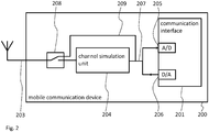
- Fig. 2 shows a block diagram of another mobile communication device 200.
- the mobile communication device 200 comprises a communication interface 201.
- the communication interface 201 comprises an A/D converter 205 for converting incoming analog signals 207 into digital data signals.
- the communication interface 201 comprises a D/A converter 206 for converting outgoing digital signals into outgoing analog signals 207.
- the A/D converter 205 and the D/A converter 206 may both be provided integrally with the communication interface 201 e.g. as part of a communication controller or communication IC.
- the A/D converter 205 and the D/A converter 206 may also be provided as separate elements.
- the A/D converter 205 and the D/A converter 206 are both connected to the channel simulation unit 204.
- the channel simulation unit 204 therefore receives and provides analog signals 207 and modifies the analog signals 207.
- the channel simulation unit 204 is connected to a bypass switch 208 that is connected to the antenna 203.
- the bypass switch 208 comprises a single antenna connection to antenna 203 and two switchable connections that may be coupled to the antenna 203 via the bypass switch 208.
- One of the switchable connections is connected to the channel simulation unit 204.
- the second switchable connection is connected to a bypass signal line 209 that bypasses the channel simulation unit 204 and is connected directly to the A/D converter 205 and the D/A converter 206.
- bypass switch 208 and the channel simulation unit 204 are shown as separate units. It is understood, that the channel simulation unit 204 and the bypass switch 208 may also be provided as a single unit.
- the channel simulation unit 204 may e.g. comprise an enable input or a kind of configuration input that allows enabling or disabling and configuring the type of signal modifications performed by the channel simulation unit 204.
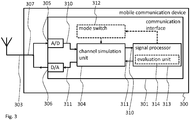
- Fig. 3 shows a block diagram of another mobile communication device 300.
- the mobile communication device 300 comprises a communication interface 301 that is connected to the antenna 303.
- the channel simulation unit 304 is not arranged between the antenna 303 and the communication interface 301. Instead, the channel simulation unit 304 is arranged within the communication interface 301 as functional unit of the communication interface 301 and is connected to a signal processor 313 of the communication interface 301 for providing incoming digital signals 310 to the signal processor 313 and for receiving outgoing digital signals 311 from the digital signal processor 313.
- the communication interface 301 provides analog signals 307 to the antenna 303.
- the channel simulation unit 304 does not process these analog signals 307. Instead, the channel simulation unit 304 being arranged in the communication interface 301 receives the digital incoming signals 310 from the A/D converter 305 and provides digital outgoing signals 311 to the D/A converter 306. This means that the channel simulation unit 304 does not need to perform analog signal processing any may therefore be implemented as a pure digital device or as a software or firmware function or module in the communication interface 301.
- the signal processor 313 and the channel simulation unit 304 are shown as separate units. It is understood, that the signal processor 313 and the channel simulation unit 304 may also be integrally formed as a single unit. This means that the signal processor 313 may e.g. comprise specific hardware units or software functions that perform the function of the channel simulation unit 304.
- the communication interface 301 of the mobile communication device 300 further comprises two additional components that may be optionally provided.
- the first is a mode switch 312.
- the mode switch 312 serves for switching the mobile communication device 300, and especially the communication interface 301 and the channel simulation unit 304, from a normal operation mode to a test mode back and forth.
- the test mode may be an operation mode, in which the channel simulation unit 304 is active, while the channel simulation unit 304 may be deactivated or bypassed in the normal operation mode.
- the second optional element is an evaluation unit 314.
- the evaluation unit 314 serves to evaluate the behavior of the mobile communication device 300 under the influence of the channel simulation unit 304.
- the evaluation unit 314 may e.g. evaluate the quality of the communication via the communication interface 301 with modified channel properties of the wireless communication channel that are modified by the channel simulation unit 314.
- the mode switch 312 and/or the evaluation unit 314 may e.g. be used in the mobile communication device 100 or the mobile communication device 200.
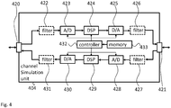
- Fig. 4 shows a block diagram of an embodiment of a channel simulation unit 404 as it may be used with the mobile communication device 100, the mobile communication device 200 and the mobile communication device 300.
- the channel simulation unit 404 is however provided for modifying analog signals. This will be apparent from the below detailed explanations.
- the channel simulation unit 404 comprises an input port 420 and an output port 421. Although called input port 420 and output port 421 it is understood that the ports 420, 421 may be bidirectional ports.
- the input port 420 may e.g. be coupled to an antenna or a bypass switch.
- the output port 421 may be coupled to the communication interface.
- the channel simulation unit 404 comprises a downlink signal path for signals received in the mobile communication device and an uplink signal path for signals transmitted from the mobile communication device.
- the downlink signal path comprises a first optional filter 422 coupled to the input port 420.
- An analog-to-digital converter 423 is coupled to the filter 422 and a digital signal processor 424 is coupled to the analog-to-digital converter 423.
- a digital-to-analog converter 425 is coupled to the digital signal processor 424 and a second optional filter is coupled between the digital-to-analog converter 425 and the output port 421.
- a third optional filter 427 is coupled to the output port 421.
- An analog-to-digital converter 428 is coupled between the filter 427 and a digital signal processor 429.
- the digital signal processor 429 is coupled to the channel simulation unit 404 via a digital-to-analog converter 430 and a fourth optional filter 431.
- the channel simulation unit 404 comprises a controller 432 and a memory 433. It is understood that the controller 432, the digital signal processor 429 and the digital signal processor 424 may be provided as a single unit. Further, the memory 433 may also be provided as part of that unit. The memory 433 may e.g. store information about required modifications of the wireless communication channel that the digital signal processor 424 and the digital signal processor 429 should perform.
- the channel simulation unit may comprise the above listed hardware units as computer program based functional units that may e.g. be executed by a controller of a communication interface.
- Fig. 5 shows a flow diagram of a method for operating a mobile communication device 100, 200, 300.
- the method comprises wirelessly communicating S1 the mobile communication device 100, 200, 300 with wireless devices 150 over a wireless communication channel 102, and simulating S2 in the mobile communication device 100, 200, 300 modified channel properties of the wireless communication channel 102.
- Wirelessly communicating S1 may comprise converting analog input signals received via a signal input of the wireless device into digital incoming signals 310 and processing the digital incoming signals 310 in the mobile communication device 100, 200, 300. Simulating S2 may then comprise modifying the analog input signals or modifying the digital input signals.
- Wirelessly communicating S1 may further comprise converting digital outgoing signals 311 of the mobile communication device 100, 200, 300 into analog outgoing signals in the mobile communication device 100, 200, 300.
- Simulating S2 may then comprise modifying the analog outgoing signals or modifying the digital outgoing signals 311.
- simulating S2 may comprise modifying properties of the wireless communication channel 102 in software and/or firmware and/or hardware.
- Simulating may e.g. be performed in a signal processing unit for processing incoming signals for the communication interface 101, 201, 301 and/or for processing outgoing signals from the communication interface 101, 201, 301.
- simulating S1 may comprise storing information about required or instructed modifications of the wireless communication channel 102 and modifying the properties of the wireless communication channel 102 based on the stored information.
- the method may further comprise controllably bypassing simulating S2 and only performing wirelessly communicating S1 the mobile communication device 100, 200, 300 in a standard operation mode of the mobile communication device 100, 200, 300. Further, the method may comprise performing simulating S1 and wirelessly communicating S2 the mobile communication device 100, 200, 300 in a test operation mode of the mobile communication device 100, 200, 300.
- the method may further comprise overlaying the wireless communication channel 102 with dedicated overlay signals and/or noise signals, and evaluating a quality of the communication via the communication interface 101, 201, 301 with modified channel properties of the wireless communication channel 102.
Landscapes
- Engineering & Computer Science (AREA)
- Physics & Mathematics (AREA)
- Computer Networks & Wireless Communication (AREA)
- Signal Processing (AREA)
- Electromagnetism (AREA)
- Quality & Reliability (AREA)
- Spectroscopy & Molecular Physics (AREA)
- Mobile Radio Communication Systems (AREA)
- Telephone Function (AREA)
Abstract
Description
- The present invention relates to a mobile communication device. The present invention further relates to a method for operating a mobile communication device.
- Although applicable in principal to any communication system, the present invention and its underlying problem will be hereinafter described in combination with wireless mobile devices.
- Modern communication systems increasingly use wireless communication between the single devices. During development, production or in the field of devices for such communication systems it is necessary to thoroughly test the wireless communication capabilities of the devices for compliance with communication standards and legal regulations and analyze different configurations of the wireless devices in the field.
- Complex and costly test equipment is required to perform such tests. Further, the preparations for performing such tests are time consuming and the test arrangements offer little flexibility.
- Against this background, the problem addressed by the present invention is allowing simplified testing of mobile devices.
- The present invention solves this objective by a mobile communication device with the features of claim 1 and a method with the features of claim 15.
- Accordingly it is provided:
- A mobile communication device comprising a communication interface for wireless communication of the mobile communication device with wireless devices, like e.g. base stations or other mobile communication devices, over a wireless communication channel, and a channel simulation unit for simulating modified channel properties of the wireless communication channel.
- Further, it is provided:
- A method for operating a mobile communication device, the method comprising wirelessly communicating the mobile communication device with wireless devices over a wireless communication channel, and simulating in the mobile communication device modified channel properties of the wireless communication channel.
- The mobile communication device may e.g. be a smartphone or an internet-of-things wireless device or any other wireless device that communicates via the wireless communication channel. The wireless communication channel may comprise e.g. a specific frequency range in a frequency band that is specified for the communication system that the mobile communication device uses. Usually the communication channels, i.e. the respective frequency ranges, will be specified e.g. by a respective communication standard. The actual wireless communication channel that the mobile communication device uses for communication may e.g. be determined by a base station to which the communication device is connected.
- The communication interface may also be called the modem of the mobile communication device and manage the communication of the mobile communication device via the wireless communication channel. The communication interface therefore serves to convert e.g. digital voice or data signals into waveforms, i.e. analog signals, that may transmit the digital voice or data signals via the wireless communication channel. Further, the communication interface will convert received waveforms or analog signals into digital voice or data signals that may then be further processed in the mobile communication device.
- The channel simulation unit serves to modify properties of the wireless communication channel, such properties may refer to different aspects of the wireless communication channel like attenuations, reflections, Doppler shifts, range delays, fading and noise. The channel simulation unit may modify any of the above mentioned aspects individually or in combination.
- With the mobile communication device of the present patent application it is therefore possible to provide the mobile communication device with an increased self-testing capability.
- It is for example possible to update the communication interface with a new waveform. "Waveform" in this regard refers to a set of parameters for the wireless communication via the wireless communication channel, like e.g. the used frequencies, the type of modulation scheme that should be used or any other relevant parameters. With the integrated channel simulation unit it is now possible to directly verify the behavior of such a waveform with the actual mobile communication device.
- An operator of a mobile device communication system may with this arrangement e.g. perform automated over-the-air configurations of the mobile communication devices and monitor the mobile communication devices for example with the same waveforms under different geographic circumstances, e.g. in a city or in mountains. The mobile communication devices can e.g. also be provided with different waveforms in the same geographic area. The results of such tests may then e.g. be provided by the mobile communication device via the communication interface to a central test server.
- Further embodiments of the present invention are subject of the further subclaims and of the following description, referring to the drawings.
- In a possible embodiment, the communication interface may comprise an analog-to-digital converter coupled to a signal input of the mobile communication device and a first signal processor for processing digital signals provided by the analog-to-digital converter.
- The signal input may e.g. comprise an antenna or antenna array of the mobile communication device. The analog-to-digital converter, ADC, may be coupled to the signal input and convert the analog signals received by the signal input into digital signals that may then be further processed by the first signal processor. The first signal processor may be any type of processing device, like e.g. an AISC, a DSP, a FPGA or the like. The first signal processor may also be integrated into another processing unit of the mobile communication device as firmware or software functions.
- In a possible embodiment, the channel simulation unit may be arranged between the signal input and the analog-to-digital converter.
- The channel simulation unit may be an individual or discrete unit that is provided in the mobile communication device in the analog part of the signal chain. It is understood that the channel simulation unit may comprise any necessary elements to process analog signals. Such elements may e.g. comprise any one of or a combination of input filters, ADCs, signal processors, DACs, and output filters.
- With such a channel simulation unit it is possible to test at least part of the analog signal chain in the mobile communication device, especially the analog-to-digital converter of the communication interface in addition to the digital signal chain in the mobile communication device.
- In a possible embodiment, the channel simulation unit may be arranged between the analog-to-digital converter and the first signal processor.
- In contrast to the above embodiment a pure digital channel simulation unit may be provided between the analog-to-digital converter and the first signal processor. This allows simplifying the channel simulation unit. The channel simulation unit may e.g. be provided as pure firmware or software function in a firmware or software that is executed by the first signal processor. The channel simulation unit may receive the digital data from the analog-to-digital converter, perform respective processing for introducing the channel simulation modifications, and forward the modified digital data to the first signal processor, i.e. the signal processing functions in the first signal processor.
- In a possible embodiment, the communication interface may comprise a digital-to-analog converter coupled to a signal output of the mobile communication device for converting digital signals provided by a second signal processor into analog signals.
- The signal output may e.g. also comprise an antenna or antenna array of the mobile communication device. It is understood, that the signal output and the signal input may comprise the same antenna or antenna array. The digital-to-analog converter, DAC, may be coupled to the second signal processor and convert the digital signals provided by the second signal processor into analog waveforms for transmission via the signal output. The second signal processor may be any type of processing device, like e.g. an AISC, a DSP, a FPGA or the like. The second signal processor may also be integrated into another processing unit of the mobile communication device as firmware or software functions. It is further understood that the first and the second signal processors may be integrally formed as a single device, firmware or software.
- In a possible embodiment, the channel simulation unit may be arranged between the digital-to-analog converter and the signal output.
- As already explained above, the channel simulation unit may be an individual or discrete unit that is provided in the mobile communication device in the analog part of the signal chain. With such a channel simulation unit it is further possible to test at least part of the analog signal chain in the mobile communication device, especially the digital-to-analog converter of the communication interface, in addition to the digital signal chain in the mobile communication device.
- In a possible embodiment, the channel simulation unit may be arranged between the digital-to-analog converter and the second signal processor.
- In contrast to the above embodiment a pure digital channel simulation unit may be provided between the digital-to-analog converter and the second signal processor. This allows simplifying the channel simulation unit and providing the channel simulation unit e.g. as pure firmware or software function in a firmware or software that is executed by the second signal processor. The channel simulation unit may receive the digital data from the second signal processor, perform respective processing for introducing the channel simulation modifications, and forward the modified digital data to the digital-to-analog converter. The digital-to-analog converter will then forward respective analog data to the analog signal chain for wireless transmission, e.g. via an antenna or antenna array of the mobile communication device.
- From the above it may be seen that the channel simulation unit may comprise a downstream section and an upstream section. The downstream section may refer to the channel simulation unit in conjunction with the analog-to-digital converter and the first signal processor. The upstream section may refer to the channel simulation unit in conjunction with the digital-to-analog converter and the second signal processor.
- In an embodiment where the first signal processor and the second signal processor are a single signal processor, the channel simulation unit may also be a single channel simulation unit for the downstream and the upstream.
- In a possible embodiment, the channel simulation unit may comprise software and/or firmware and/or hardware elements.
- Above examples for possible channel simulation units have been given, where the channel simulation unit comprises either firmware or software or hardware. It is however understood, that any combination of software and hardware is possible.
- The channel simulation unit, i.e. single elements of the channel simulation unit, may in the downlink therefore be arranged between the signal input and the analog-to-digital converter as well as between the analog-to-digital converter and the first signal processor. In the uplink the channel simulation unit, i.e. its elements, may be provided between the digital-to-analog converter and the signal output as well as between the digital-to-analog converter and the second signal processor.
- In a possible embodiment, the mobile communication device may comprise a controllable bypass device for controllably bypassing the channel simulation unit.
- Bypassing in this context refers to forwarding signals without active intervention of the channel simulation unit. The controllable bypass device may therefore e.g. be a hardware switching device that forwards signals around the channel simulation unit. The controllable bypass device may in addition or as an alternative also be a software or firmware switch. Such a software or firmware switch may cause certain channel simulation unit functions to be actively called in an active mode of the channel simulation unit. In an inactive mode of the channel simulation unit such software or firmware switches may cause the respective functions to be skipped.
- In a possible embodiment, the channel simulation unit may comprise a signal processing unit for processing incoming signals for the communication interface and/or for processing outgoing signals from the communication interface.
- The signal processing unit may e.g. be a discrete unit like a DSP, e.g. with corresponding filters, ADCs, DACs and the like. In addition or as an alternative the signal processing unit may also be a software or firmware in the first signal processor and/or second signal processor without dedicated analog circuitry for the signal processing unit.
- In a possible embodiment, the channel simulation unit may comprise a memory for storing information about required or instructed modifications of the wireless communication channel.
- The memory may be a discrete memory or comprise variables in a memory of the communication interface. The stored information may e.g. specify the details of the signal modifications like e.g. delay modifications, phase shift modifications, carrier or signal Doppler modifications, attenuation modifications and the like.
- Such information may be pre-stored in the memory and may be retrieved when a specific test is started. In addition or as alternative such information may be provided wirelessly via the wireless communication channel.
- In a possible embodiment, the signal processing unit may comprise a signal generator and/or a noise generator for overlaying wireless communication channel, i.e. the incoming and outgoing signals, with dedicated overlay signals and/or noise signals.
- The ability to overlay the incoming and outgoing signals in the wireless communication channel with generated signals or noise increases the possible tests and modifications that may be performed with the wireless communication channel.
- In a possible embodiment, the mobile communication device may comprise a mode switch for switching the mobile communication device into a test mode, wherein the channel simulation unit may only be active when the mobile communication device is in the test mode.
- The mode switch may be a hardware or software switch that may be controlled e.g. by a firmware or software of the mobile communication device and that may activate or deactivate the channel simulation unit.
- The mode switch may also be controlled remotely, e.g. with support of the firmware or software that may comprise a remote control interface, by an operator of the communication system in which the mobile communication device is used.
- In a possible embodiment, the mobile communication device may comprise an evaluation unit for evaluating a quality of the communication via the communication interface with modified channel properties of the wireless communication channel that are modified by the channel simulation unit.
- The evaluation unit allows automatically evaluating the results of a channel simulation in the mobile communication device. Evaluating the results in this context may refer e.g. to determining a signal-to-noise ratio, an error rate, a data rate, a voice quality or any other property of the wireless communication channel under the respective simulated channel conditions.
- An operator of a communication system may e.g. perform tests of different waveforms that may be used in the communication system and determine the waveform with the best failure rate, the highest communication rates, the most stable voice communication or the like.
- For a more complete understanding of the present invention and advantages thereof, reference is now made to the following description taken in conjunction with the accompanying drawings. The invention is explained in more detail below using exemplary embodiments which are specified in the schematic figures of the drawings, in which:
- Fig. 1
- shows a block diagram of an embodiment of a mobile communication device according to the present invention;
- Fig. 2
- shows a block diagram of another embodiment of a mobile communication device according to the present invention;
- Fig. 3
- shows a block diagram of another embodiment of a mobile communication device according to the present invention;
- Fig. 4
- shows a block diagram of an embodiment of a channel simulation unit according to the present invention; and
- Fig. 5
- shows a flow diagram of an embodiment of a method according to the present invention.
- The appended drawings are intended to provide further understanding of the embodiments of the invention. They illustrate embodiments and, in conjunction with the description, help to explain principles and concepts of the invention. Other embodiments and many of the advantages mentioned become apparent in view of the drawings. The elements in the drawings are not necessarily shown to scale.
- In the drawings, like, functionally equivalent and identically operating elements, features and components are provided with like reference signs in each case, unless stated otherwise.
-
Fig. 1 shows a block diagram of amobile communication device 100. Themobile communication device 100 may be any type of communication device that uses wireless communication to communicate with other devices. Such amobile communication device 100 may e.g. be a mobile phone, an internet of things device, a wireless network device or any other type of wireless device. - The
mobile communication device 100 comprises acommunication interface 101 that is coupled to anantenna 103 for communicating themobile communication device 100 via awireless communication channel 102 with other wireless devices 150 (only one shown) that may also comprise anantenna 151. - The
mobile communication device 100 further comprises achannel simulation unit 104 that may modify the properties of any signals that are received or transmitted by thecommunication interface 101 via theantenna 103. - The
communication interface 101 may also be called the modem or modem component of themobile communication device 100. Such acommunication interface 101 may e.g. be provided as a combination of hardware and software. For example a communication protocol stack may be executed by a processor of themobile communication device 100. The protocol stack may provide respective digital signals that may be converted into analog signals by hardware components of thecommunication interface 101 for transmission by theantenna 103. The same applies mutatis mutandis for signal reception. - The
channel simulation unit 104 may modify properties of thewireless communication channel 102. The properties may e.g. refer to attenuations, reflections, Doppler shifts, range delays, fading and noise. This means that thechannel simulation unit 104 may add any of the above attenuations, reflections, Doppler shifts, range delays, fading and noise alone or in combination to the signals received or transmitted via theantenna 103. - The
channel simulation unit 104 may therefore comprise any analog and/or digital signal processing means necessary to perform such modifications. - In the following description of
Figs. 2 - 3 different arrangements of thechannel simulation unit 104 will be exemplarily described. -
Fig. 2 shows a block diagram of anothermobile communication device 200. Themobile communication device 200 comprises acommunication interface 201. Thecommunication interface 201 comprises an A/D converter 205 for convertingincoming analog signals 207 into digital data signals. In addition, thecommunication interface 201 comprises a D/A converter 206 for converting outgoing digital signals into outgoing analog signals 207. The A/D converter 205 and the D/A converter 206 may both be provided integrally with thecommunication interface 201 e.g. as part of a communication controller or communication IC. As alternative the A/D converter 205 and the D/A converter 206 may also be provided as separate elements. - The A/
D converter 205 and the D/A converter 206 are both connected to thechannel simulation unit 204. In themobile communication device 200 thechannel simulation unit 204 therefore receives and providesanalog signals 207 and modifies the analog signals 207. - The
channel simulation unit 204 is connected to abypass switch 208 that is connected to theantenna 203. Thebypass switch 208 comprises a single antenna connection toantenna 203 and two switchable connections that may be coupled to theantenna 203 via thebypass switch 208. One of the switchable connections is connected to thechannel simulation unit 204. The second switchable connection is connected to abypass signal line 209 that bypasses thechannel simulation unit 204 and is connected directly to the A/D converter 205 and the D/A converter 206. - In the
mobile communication device 200 thebypass switch 208 and thechannel simulation unit 204 are shown as separate units. It is understood, that thechannel simulation unit 204 and thebypass switch 208 may also be provided as a single unit. Thechannel simulation unit 204 may e.g. comprise an enable input or a kind of configuration input that allows enabling or disabling and configuring the type of signal modifications performed by thechannel simulation unit 204. -
Fig. 3 shows a block diagram of anothermobile communication device 300. Themobile communication device 300 comprises acommunication interface 301 that is connected to theantenna 303. In contrast to themobile communication device 200, thechannel simulation unit 304 is not arranged between theantenna 303 and thecommunication interface 301. Instead, thechannel simulation unit 304 is arranged within thecommunication interface 301 as functional unit of thecommunication interface 301 and is connected to asignal processor 313 of thecommunication interface 301 for providing incomingdigital signals 310 to thesignal processor 313 and for receiving outgoingdigital signals 311 from thedigital signal processor 313. - As in
mobile communication device 200 thecommunication interface 301 providesanalog signals 307 to theantenna 303. - However, the
channel simulation unit 304 does not process these analog signals 307. Instead, thechannel simulation unit 304 being arranged in thecommunication interface 301 receives the digitalincoming signals 310 from the A/D converter 305 and provides digitaloutgoing signals 311 to the D/A converter 306. This means that thechannel simulation unit 304 does not need to perform analog signal processing any may therefore be implemented as a pure digital device or as a software or firmware function or module in thecommunication interface 301. - In the
communication interface 301 thesignal processor 313 and thechannel simulation unit 304 are shown as separate units. It is understood, that thesignal processor 313 and thechannel simulation unit 304 may also be integrally formed as a single unit. This means that thesignal processor 313 may e.g. comprise specific hardware units or software functions that perform the function of thechannel simulation unit 304. - The
communication interface 301 of themobile communication device 300 further comprises two additional components that may be optionally provided. The first is amode switch 312. Themode switch 312 serves for switching themobile communication device 300, and especially thecommunication interface 301 and thechannel simulation unit 304, from a normal operation mode to a test mode back and forth. The test mode may be an operation mode, in which thechannel simulation unit 304 is active, while thechannel simulation unit 304 may be deactivated or bypassed in the normal operation mode. - The second optional element is an
evaluation unit 314. Theevaluation unit 314 serves to evaluate the behavior of themobile communication device 300 under the influence of thechannel simulation unit 304. Theevaluation unit 314 may e.g. evaluate the quality of the communication via thecommunication interface 301 with modified channel properties of the wireless communication channel that are modified by thechannel simulation unit 314. - It is understood, that the above embodiments are only exemplary and that the single features of the
mobile communication device 100, themobile communication device 200, and themobile communication device 300 may be freely combined. Themode switch 312 and/or theevaluation unit 314 may e.g. be used in themobile communication device 100 or themobile communication device 200. -
Fig. 4 shows a block diagram of an embodiment of achannel simulation unit 404 as it may be used with themobile communication device 100, themobile communication device 200 and themobile communication device 300. Thechannel simulation unit 404 is however provided for modifying analog signals. This will be apparent from the below detailed explanations. - The
channel simulation unit 404 comprises aninput port 420 and anoutput port 421. Although calledinput port 420 andoutput port 421 it is understood that theports input port 420 may e.g. be coupled to an antenna or a bypass switch. Theoutput port 421 may be coupled to the communication interface. - The
channel simulation unit 404 comprises a downlink signal path for signals received in the mobile communication device and an uplink signal path for signals transmitted from the mobile communication device. - The downlink signal path comprises a first
optional filter 422 coupled to theinput port 420. An analog-to-digital converter 423 is coupled to thefilter 422 and adigital signal processor 424 is coupled to the analog-to-digital converter 423. In addition a digital-to-analog converter 425 is coupled to thedigital signal processor 424 and a second optional filter is coupled between the digital-to-analog converter 425 and theoutput port 421. - In the uplink path a third
optional filter 427 is coupled to theoutput port 421. An analog-to-digital converter 428 is coupled between thefilter 427 and adigital signal processor 429. Thedigital signal processor 429 is coupled to thechannel simulation unit 404 via a digital-to-analog converter 430 and a fourthoptional filter 431. - Further, the
channel simulation unit 404 comprises acontroller 432 and amemory 433. It is understood that thecontroller 432, thedigital signal processor 429 and thedigital signal processor 424 may be provided as a single unit. Further, thememory 433 may also be provided as part of that unit. Thememory 433 may e.g. store information about required modifications of the wireless communication channel that thedigital signal processor 424 and thedigital signal processor 429 should perform. - It is understood, that in other embodiments the channel simulation unit may comprise the above listed hardware units as computer program based functional units that may e.g. be executed by a controller of a communication interface.
- For sake of clarity in the following description of the method based
Fig. 5 the reference signs used above in the description of apparatus basedFigs. 1 - 4 will be maintained. -
Fig. 5 shows a flow diagram of a method for operating amobile communication device - The method comprises wirelessly communicating S1 the
mobile communication device wireless devices 150 over awireless communication channel 102, and simulating S2 in themobile communication device wireless communication channel 102. - Wirelessly communicating S1 may comprise converting analog input signals received via a signal input of the wireless device into digital
incoming signals 310 and processing the digitalincoming signals 310 in themobile communication device - Wirelessly communicating S1 may further comprise converting digital
outgoing signals 311 of themobile communication device mobile communication device outgoing signals 311. - In addition simulating S2 may comprise modifying properties of the
wireless communication channel 102 in software and/or firmware and/or hardware. - Simulating may e.g. be performed in a signal processing unit for processing incoming signals for the
communication interface communication interface - In addition, simulating S1 may comprise storing information about required or instructed modifications of the
wireless communication channel 102 and modifying the properties of thewireless communication channel 102 based on the stored information. - The method may further comprise controllably bypassing simulating S2 and only performing wirelessly communicating S1 the
mobile communication device mobile communication device mobile communication device mobile communication device - The method may further comprise overlaying the
wireless communication channel 102 with dedicated overlay signals and/or noise signals, and evaluating a quality of the communication via thecommunication interface wireless communication channel 102. - Although specific embodiments have been illustrated and described herein, it will be appreciated by those of ordinary skill in the art that a variety of alternate and/or equivalent implementations exist. It should be appreciated that the exemplary embodiment or exemplary embodiments are only examples, and are not intended to limit the scope, applicability, or configuration in any way. Rather, the foregoing summary and detailed description will provide those skilled in the art with a convenient road map for implementing at least one exemplary embodiment, it being understood that various changes may be made in the function and arrangement of elements described in an exemplary embodiment without departing from the scope as set forth in the appended claims and their legal equivalents. Generally, this application is intended to cover any adaptations or variations of the specific embodiments discussed herein.
- In the foregoing detailed description, various features are grouped together in one or more examples or examples for the purpose of streamlining the disclosure. It is understood that the above description is intended to be illustrative, and not restrictive. It is intended to cover all alternatives, modifications and equivalents as may be included within the scope of the invention. Many other examples will be apparent to one skilled in the art upon reviewing the above specification.
- Specific nomenclature used in the foregoing specification is used to provide a thorough understanding of the invention. However, it will be apparent to one skilled in the art in light of the specification provided herein that the specific details are not required in order to practice the invention. Thus, the foregoing descriptions of specific embodiments of the present invention are presented for purposes of illustration and description. They are not intended to be exhaustive or to limit the invention to the precise forms disclosed; obviously many modifications and variations are possible in view of the above teachings. The embodiments were chosen and described in order to best explain the principles of the invention and its practical applications, to thereby enable others skilled in the art to best utilize the invention and various embodiments with various modifications as are suited to the particular use contemplated. Throughout the specification, the terms "including" and "in which" are used as the plain-English equivalents of the respective terms "comprising" and "wherein," respectively. Moreover, the terms "first," "second," and "third," etc., are used merely as labels, and are not intended to impose numerical requirements on or to establish a certain ranking of importance of their objects.
-
- 100, 200, 300
- mobile communication device
- 101, 201, 301
- communication interface
- 102
- wireless communication channel
- 103, 203, 303
- antenna
- 104, 204, 304, 404
- channel simulation unit
- 205, 305
- analog-to-digital converter
- 206, 306
- digital-to-analog converter
- 207, 307
- analog signal
- 208
- bypass switch
- 209
- bypass signal line
- 310
- digital incoming signal
- 311
- digital outgoing signal
- 312
- mode switch
- 313
- signal processor
- 314
- evaluation unit
- 420
- input port
- 421
- output port
- 422
- filter
- 423
- analog-to-digital converter
- 424
- processor
- 425
- digital-to-analog converter
- 426
- filter
- 427
- filter
- 428
- analog-to-digital converter
- 429
- processor
- 430
- digital-to-analog converter
- 431
- filter
- 432
- controller
- 433
- memory
- 150
- wireless devices
- 151
- antenna
- S1, S2
- method steps
Claims (15)
- Mobile communication device comprising:a communication interface for wireless communication of the mobile communication device with wireless devices over a wireless communication channel, anda channel simulation unit for simulating modified channel properties of the wireless communication channel.
- Mobile communication device according to claim 1, wherein the communication interface comprises an analog-to-digital converter coupled to a signal input of the mobile communication device and a first signal processor for processing digital incoming signals provided by the analog-to-digital converter.
- Mobile communication device according to claim 2, wherein the channel simulation unit is arranged between the signal input and the analog-to-digital converter; or
wherein the channel simulation unit is arranged between the analog-to-digital converter and the first signal processor. - Mobile communication device according to any one of the preceding claims, wherein the communication interface comprises a digital-to-analog converter coupled to a signal output of the mobile communication device for converting digital signals provided by a second signal processor into analog outgoing signals.
- Mobile communication device according to claim 4, wherein the channel simulation unit is arranged between the digital-to-analog converter and the signal output; or
wherein the channel simulation unit is arranged between the digital-to-analog converter and the second signal processor. - Mobile communication device according to any one of the preceding claims, comprising a controllable bypass device for controllably bypassing the channel simulation unit.
- Mobile communication device according to any one of the preceding claims, wherein the channel simulation unit comprises a signal processing unit for processing incoming signals for the communication interface and/or for processing outgoing signals from the communication interface; and/or
wherein the channel simulation unit comprises software and/or firmware and/or hardware elements. - Mobile communication device according to any one of the preceding claims, wherein the channel simulation unit comprises a memory for storing information about required or instructed modifications of the wireless communication channel; and/or.
wherein the signal processing unit comprises a signal generator and/or a noise generator for overlaying wireless communication channel with dedicated overlay signals and/or noise signals. - Mobile communication device according to any one of the preceding claims, comprising a mode switch for switching the mobile communication device into a test mode, wherein the channel simulation unit is only active when the mobile communication device is in the test mode; and/or
comprising an evaluation unit for evaluating a quality of the communication via the communication interface with modified channel properties of the wireless communication channel that are modified by the channel simulation unit. - Method for operating a mobile communication device with a communication interface for communication via a wireless communication channel, the method comprising:wirelessly communicating the mobile communication device with wireless devices over a wireless communication channel,simulating in the mobile communication device modified channel properties of the wireless communication channel.
- Method according to claim 10, wherein wirelessly communicating comprises, in the mobile communication device, converting analog input signals received via a signal input of the wireless device into digital incoming signals and processing the digital incoming signals, especially wherein simulating comprises modifying the analog input signals, or modifying the digital input signals.
- Method according to claims 10 and 11, wherein wirelessly communicating comprises, in the mobile communication device, converting digital outgoing signals of the mobile communication device into analog outgoing signals, especially wherein simulating comprises modifying the analog outgoing signals, or the digital outgoing signals.
- Method according to claims 10 to 12, comprising controllably bypassing simulating and only performing wirelessly communicating the mobile communication device in a standard operation mode of the mobile communication device, and comprising performing simulating and wirelessly communicating the mobile communication device in a test operation mode of the mobile communication device; and/or
comprising overlaying the wireless communication channel with dedicated overlay signals and/or noise signals; and/or
comprising evaluating a quality of the communication via the communication interface with modified channel properties of the wireless communication channel. - Method according to claims 10 to 13, wherein simulating is performed in a signal processing unit for processing incoming signals for the communication interface and/or for processing outgoing signals from the communication interface; and/or wherein simulating comprises modifying properties of the wireless communication channel in software and/or firmware and/or hardware.
- Method according to claims 10 to 14, wherein simulating comprises storing information about required or instructed modifications of the wireless communication channel and modifying the properties of the wireless communication channel based on the stored information.
Applications Claiming Priority (1)
| Application Number | Priority Date | Filing Date | Title |
|---|---|---|---|
| US15/581,746 US10142867B2 (en) | 2017-04-28 | 2017-04-28 | Mobile communication device and method |
Publications (2)
| Publication Number | Publication Date |
|---|---|
| EP3396873A1 true EP3396873A1 (en) | 2018-10-31 |
| EP3396873B1 EP3396873B1 (en) | 2021-04-07 |
Family
ID=60627406
Family Applications (1)
| Application Number | Title | Priority Date | Filing Date |
|---|---|---|---|
| EP17203744.2A Active EP3396873B1 (en) | 2017-04-28 | 2017-11-27 | Mobile communication device and method |
Country Status (3)
| Country | Link |
|---|---|
| US (1) | US10142867B2 (en) |
| EP (1) | EP3396873B1 (en) |
| CN (1) | CN108809457B (en) |
Families Citing this family (1)
| Publication number | Priority date | Publication date | Assignee | Title |
|---|---|---|---|---|
| CN114362857A (en) * | 2021-12-09 | 2022-04-15 | 中电科思仪科技股份有限公司 | GIS-based channel simulation device and method |
Citations (2)
| Publication number | Priority date | Publication date | Assignee | Title |
|---|---|---|---|---|
| US6236363B1 (en) * | 1998-01-30 | 2001-05-22 | Micronetics Wireless | Smart antenna channel simulator and test system |
| US20080280566A1 (en) * | 2007-05-07 | 2008-11-13 | Kuang-Yu Yen | Wireless communication apparatus with built-in channel emulator/noise generator |
Family Cites Families (4)
| Publication number | Priority date | Publication date | Assignee | Title |
|---|---|---|---|---|
| CN101521547A (en) * | 2008-02-26 | 2009-09-02 | 瑞昱半导体股份有限公司 | Wireless communication device with built-in channel simulator/noise generator |
| EP2351409A4 (en) * | 2008-11-24 | 2013-11-06 | Ericsson Telefon Ab L M | Method and device in an over-the-air test environment |
| US9407381B2 (en) * | 2012-09-27 | 2016-08-02 | Keysight Technologies Singapore (Holdings) Pte. Ltd. | Radio channel emulation |
| US9661517B2 (en) * | 2015-06-22 | 2017-05-23 | Ixia | Systems and methods for mobility testing of MU-MIMO |
-
2017
- 2017-04-28 US US15/581,746 patent/US10142867B2/en active Active
- 2017-11-27 EP EP17203744.2A patent/EP3396873B1/en active Active
-
2018
- 2018-01-10 CN CN201810021724.2A patent/CN108809457B/en active Active
Patent Citations (2)
| Publication number | Priority date | Publication date | Assignee | Title |
|---|---|---|---|---|
| US6236363B1 (en) * | 1998-01-30 | 2001-05-22 | Micronetics Wireless | Smart antenna channel simulator and test system |
| US20080280566A1 (en) * | 2007-05-07 | 2008-11-13 | Kuang-Yu Yen | Wireless communication apparatus with built-in channel emulator/noise generator |
Non-Patent Citations (1)
| Title |
|---|
| ANDY D FONTAINE ET AL: "A multipath channel emulator integrated with a QAM modulator", ELECTRICAL AND COMPUTER ENGINEERING (CCECE), 2013 26TH ANNUAL IEEE CANADIAN CONFERENCE ON, IEEE, 5 May 2013 (2013-05-05), pages 1 - 4, XP032440397, ISBN: 978-1-4799-0031-2, DOI: 10.1109/CCECE.2013.6567737 * |
Also Published As
| Publication number | Publication date |
|---|---|
| CN108809457A (en) | 2018-11-13 |
| CN108809457B (en) | 2021-12-21 |
| US10142867B2 (en) | 2018-11-27 |
| EP3396873B1 (en) | 2021-04-07 |
| US20180317105A1 (en) | 2018-11-01 |
Similar Documents
| Publication | Publication Date | Title |
|---|---|---|
| US10419134B2 (en) | Configuration sub-system for telecommunication systems | |
| US9306682B2 (en) | Systems and methods for a self-optimizing distributed antenna system | |
| JP6383380B2 (en) | Mobile terminal test apparatus and test method | |
| JP2014508435A (en) | Carrier test method, apparatus and computer program | |
| US10182355B1 (en) | Methods, systems and computer readable media for testing an air interface device by simulating multi-user equipment (multi-UE) uplink virtual multiple input multiple output (MIMO) | |
| EP1186124B1 (en) | Apparatus for testing mobile phones | |
| US20080280566A1 (en) | Wireless communication apparatus with built-in channel emulator/noise generator | |
| JP2016518745A (en) | System and method for testing a radio frequency multiplexed input / output data packet transceiver while forcing data stream reduction | |
| CN114374408A (en) | Anti-interference test system | |
| US10142867B2 (en) | Mobile communication device and method | |
| CN105375939B (en) | A kind of reception method for compensating signal | |
| CN121417956A (en) | Satellite communication terminal testing system | |
| CN106034002A (en) | Multichannel wideband channel simulation method and device | |
| US11363559B2 (en) | Method and test system for testing an integrated access backhaul node | |
| KR101986360B1 (en) | massive channel simulator with wide scope path delay | |
| EP3402241B1 (en) | System simulator and simulation method | |
| WO2016188482A1 (en) | Detection method and apparatus | |
| US20050107041A1 (en) | Multi-net | |
| JP5426638B2 (en) | Mobile communication terminal test system and test method | |
| JP3699064B2 (en) | Radio base station test system and radio base station test method | |
| US20200186457A1 (en) | Test System For Rack And Electronic Devices Disposed In The Rack And Method Thereof | |
| CN118487648A (en) | A multi-carrier transmission performance test system and method for a multi-beam satellite communication system | |
| KR101129274B1 (en) | Position location test apparatus and method | |
| KR101061511B1 (en) | Remotely controlled communication terminal device | |
| Johari Varnoosfaderani | Economical Debug Station For debugging 3G modem |
Legal Events
| Date | Code | Title | Description |
|---|---|---|---|
| PUAI | Public reference made under article 153(3) epc to a published international application that has entered the european phase |
Free format text: ORIGINAL CODE: 0009012 |
|
| STAA | Information on the status of an ep patent application or granted ep patent |
Free format text: STATUS: THE APPLICATION HAS BEEN PUBLISHED |
|
| AK | Designated contracting states |
Kind code of ref document: A1 Designated state(s): AL AT BE BG CH CY CZ DE DK EE ES FI FR GB GR HR HU IE IS IT LI LT LU LV MC MK MT NL NO PL PT RO RS SE SI SK SM TR |
|
| AX | Request for extension of the european patent |
Extension state: BA ME |
|
| STAA | Information on the status of an ep patent application or granted ep patent |
Free format text: STATUS: REQUEST FOR EXAMINATION WAS MADE |
|
| 17P | Request for examination filed |
Effective date: 20190424 |
|
| RBV | Designated contracting states (corrected) |
Designated state(s): AL AT BE BG CH CY CZ DE DK EE ES FI FR GB GR HR HU IE IS IT LI LT LU LV MC MK MT NL NO PL PT RO RS SE SI SK SM TR |
|
| STAA | Information on the status of an ep patent application or granted ep patent |
Free format text: STATUS: EXAMINATION IS IN PROGRESS |
|
| 17Q | First examination report despatched |
Effective date: 20190927 |
|
| REG | Reference to a national code |
Ref country code: DE Ref legal event code: R079 Ref document number: 602017036077 Country of ref document: DE Free format text: PREVIOUS MAIN CLASS: H04B0017391000 Ipc: H04B0017309000 |
|
| GRAP | Despatch of communication of intention to grant a patent |
Free format text: ORIGINAL CODE: EPIDOSNIGR1 |
|
| STAA | Information on the status of an ep patent application or granted ep patent |
Free format text: STATUS: GRANT OF PATENT IS INTENDED |
|
| RIC1 | Information provided on ipc code assigned before grant |
Ipc: H04B 17/391 20150101ALI20200928BHEP Ipc: H04B 17/309 20150101AFI20200928BHEP |
|
| INTG | Intention to grant announced |
Effective date: 20201014 |
|
| GRAS | Grant fee paid |
Free format text: ORIGINAL CODE: EPIDOSNIGR3 |
|
| GRAA | (expected) grant |
Free format text: ORIGINAL CODE: 0009210 |
|
| STAA | Information on the status of an ep patent application or granted ep patent |
Free format text: STATUS: THE PATENT HAS BEEN GRANTED |
|
| AK | Designated contracting states |
Kind code of ref document: B1 Designated state(s): AL AT BE BG CY CZ DE DK EE ES FI FR GB GR HR HU IS IT LT LU LV MC MK MT NL NO PL PT RO RS SE SI SK SM TR |
|
| RBV | Designated contracting states (corrected) |
Designated state(s): AL AT BE BG CY CZ DE DK EE ES FI FR GB GR HR HU IS IT LT LU LV MC MK MT NL NO PL PT RO RS SE SI SK SM TR |
|
| REG | Reference to a national code |
Ref country code: GB Ref legal event code: FG4D |
|
| REG | Reference to a national code |
Ref country code: AT Ref legal event code: REF Ref document number: 1381042 Country of ref document: AT Kind code of ref document: T Effective date: 20210415 |
|
| REG | Reference to a national code |
Ref country code: DE Ref legal event code: R096 Ref document number: 602017036077 Country of ref document: DE |
|
| REG | Reference to a national code |
Ref country code: LT Ref legal event code: MG9D |
|
| REG | Reference to a national code |
Ref country code: NL Ref legal event code: MP Effective date: 20210407 Ref country code: AT Ref legal event code: MK05 Ref document number: 1381042 Country of ref document: AT Kind code of ref document: T Effective date: 20210407 |
|
| PG25 | Lapsed in a contracting state [announced via postgrant information from national office to epo] |
Ref country code: NL Free format text: LAPSE BECAUSE OF FAILURE TO SUBMIT A TRANSLATION OF THE DESCRIPTION OR TO PAY THE FEE WITHIN THE PRESCRIBED TIME-LIMIT Effective date: 20210407 Ref country code: HR Free format text: LAPSE BECAUSE OF FAILURE TO SUBMIT A TRANSLATION OF THE DESCRIPTION OR TO PAY THE FEE WITHIN THE PRESCRIBED TIME-LIMIT Effective date: 20210407 Ref country code: BG Free format text: LAPSE BECAUSE OF FAILURE TO SUBMIT A TRANSLATION OF THE DESCRIPTION OR TO PAY THE FEE WITHIN THE PRESCRIBED TIME-LIMIT Effective date: 20210707 Ref country code: AT Free format text: LAPSE BECAUSE OF FAILURE TO SUBMIT A TRANSLATION OF THE DESCRIPTION OR TO PAY THE FEE WITHIN THE PRESCRIBED TIME-LIMIT Effective date: 20210407 Ref country code: LT Free format text: LAPSE BECAUSE OF FAILURE TO SUBMIT A TRANSLATION OF THE DESCRIPTION OR TO PAY THE FEE WITHIN THE PRESCRIBED TIME-LIMIT Effective date: 20210407 Ref country code: FI Free format text: LAPSE BECAUSE OF FAILURE TO SUBMIT A TRANSLATION OF THE DESCRIPTION OR TO PAY THE FEE WITHIN THE PRESCRIBED TIME-LIMIT Effective date: 20210407 |
|
| PG25 | Lapsed in a contracting state [announced via postgrant information from national office to epo] |
Ref country code: RS Free format text: LAPSE BECAUSE OF FAILURE TO SUBMIT A TRANSLATION OF THE DESCRIPTION OR TO PAY THE FEE WITHIN THE PRESCRIBED TIME-LIMIT Effective date: 20210407 Ref country code: SE Free format text: LAPSE BECAUSE OF FAILURE TO SUBMIT A TRANSLATION OF THE DESCRIPTION OR TO PAY THE FEE WITHIN THE PRESCRIBED TIME-LIMIT Effective date: 20210407 Ref country code: PT Free format text: LAPSE BECAUSE OF FAILURE TO SUBMIT A TRANSLATION OF THE DESCRIPTION OR TO PAY THE FEE WITHIN THE PRESCRIBED TIME-LIMIT Effective date: 20210809 Ref country code: NO Free format text: LAPSE BECAUSE OF FAILURE TO SUBMIT A TRANSLATION OF THE DESCRIPTION OR TO PAY THE FEE WITHIN THE PRESCRIBED TIME-LIMIT Effective date: 20210707 Ref country code: PL Free format text: LAPSE BECAUSE OF FAILURE TO SUBMIT A TRANSLATION OF THE DESCRIPTION OR TO PAY THE FEE WITHIN THE PRESCRIBED TIME-LIMIT Effective date: 20210407 Ref country code: IS Free format text: LAPSE BECAUSE OF FAILURE TO SUBMIT A TRANSLATION OF THE DESCRIPTION OR TO PAY THE FEE WITHIN THE PRESCRIBED TIME-LIMIT Effective date: 20210807 Ref country code: GR Free format text: LAPSE BECAUSE OF FAILURE TO SUBMIT A TRANSLATION OF THE DESCRIPTION OR TO PAY THE FEE WITHIN THE PRESCRIBED TIME-LIMIT Effective date: 20210708 Ref country code: LV Free format text: LAPSE BECAUSE OF FAILURE TO SUBMIT A TRANSLATION OF THE DESCRIPTION OR TO PAY THE FEE WITHIN THE PRESCRIBED TIME-LIMIT Effective date: 20210407 |
|
| REG | Reference to a national code |
Ref country code: DE Ref legal event code: R097 Ref document number: 602017036077 Country of ref document: DE |
|
| PG25 | Lapsed in a contracting state [announced via postgrant information from national office to epo] |
Ref country code: SM Free format text: LAPSE BECAUSE OF FAILURE TO SUBMIT A TRANSLATION OF THE DESCRIPTION OR TO PAY THE FEE WITHIN THE PRESCRIBED TIME-LIMIT Effective date: 20210407 Ref country code: SK Free format text: LAPSE BECAUSE OF FAILURE TO SUBMIT A TRANSLATION OF THE DESCRIPTION OR TO PAY THE FEE WITHIN THE PRESCRIBED TIME-LIMIT Effective date: 20210407 Ref country code: CZ Free format text: LAPSE BECAUSE OF FAILURE TO SUBMIT A TRANSLATION OF THE DESCRIPTION OR TO PAY THE FEE WITHIN THE PRESCRIBED TIME-LIMIT Effective date: 20210407 Ref country code: DK Free format text: LAPSE BECAUSE OF FAILURE TO SUBMIT A TRANSLATION OF THE DESCRIPTION OR TO PAY THE FEE WITHIN THE PRESCRIBED TIME-LIMIT Effective date: 20210407 Ref country code: EE Free format text: LAPSE BECAUSE OF FAILURE TO SUBMIT A TRANSLATION OF THE DESCRIPTION OR TO PAY THE FEE WITHIN THE PRESCRIBED TIME-LIMIT Effective date: 20210407 Ref country code: RO Free format text: LAPSE BECAUSE OF FAILURE TO SUBMIT A TRANSLATION OF THE DESCRIPTION OR TO PAY THE FEE WITHIN THE PRESCRIBED TIME-LIMIT Effective date: 20210407 Ref country code: ES Free format text: LAPSE BECAUSE OF FAILURE TO SUBMIT A TRANSLATION OF THE DESCRIPTION OR TO PAY THE FEE WITHIN THE PRESCRIBED TIME-LIMIT Effective date: 20210407 |
|
| PLBE | No opposition filed within time limit |
Free format text: ORIGINAL CODE: 0009261 |
|
| STAA | Information on the status of an ep patent application or granted ep patent |
Free format text: STATUS: NO OPPOSITION FILED WITHIN TIME LIMIT |
|
| 26N | No opposition filed |
Effective date: 20220110 |
|
| PG25 | Lapsed in a contracting state [announced via postgrant information from national office to epo] |
Ref country code: IS Free format text: LAPSE BECAUSE OF FAILURE TO SUBMIT A TRANSLATION OF THE DESCRIPTION OR TO PAY THE FEE WITHIN THE PRESCRIBED TIME-LIMIT Effective date: 20210807 Ref country code: AL Free format text: LAPSE BECAUSE OF FAILURE TO SUBMIT A TRANSLATION OF THE DESCRIPTION OR TO PAY THE FEE WITHIN THE PRESCRIBED TIME-LIMIT Effective date: 20210407 |
|
| PG25 | Lapsed in a contracting state [announced via postgrant information from national office to epo] |
Ref country code: MC Free format text: LAPSE BECAUSE OF FAILURE TO SUBMIT A TRANSLATION OF THE DESCRIPTION OR TO PAY THE FEE WITHIN THE PRESCRIBED TIME-LIMIT Effective date: 20210407 |
|
| PG25 | Lapsed in a contracting state [announced via postgrant information from national office to epo] |
Ref country code: LU Free format text: LAPSE BECAUSE OF NON-PAYMENT OF DUE FEES Effective date: 20211127 Ref country code: IT Free format text: LAPSE BECAUSE OF FAILURE TO SUBMIT A TRANSLATION OF THE DESCRIPTION OR TO PAY THE FEE WITHIN THE PRESCRIBED TIME-LIMIT Effective date: 20210407 Ref country code: BE Free format text: LAPSE BECAUSE OF NON-PAYMENT OF DUE FEES Effective date: 20211130 |
|
| REG | Reference to a national code |
Ref country code: BE Ref legal event code: MM Effective date: 20211130 |
|
| PG25 | Lapsed in a contracting state [announced via postgrant information from national office to epo] |
Ref country code: CY Free format text: LAPSE BECAUSE OF FAILURE TO SUBMIT A TRANSLATION OF THE DESCRIPTION OR TO PAY THE FEE WITHIN THE PRESCRIBED TIME-LIMIT Effective date: 20210407 |
|
| P01 | Opt-out of the competence of the unified patent court (upc) registered |
Effective date: 20230525 |
|
| PG25 | Lapsed in a contracting state [announced via postgrant information from national office to epo] |
Ref country code: HU Free format text: LAPSE BECAUSE OF FAILURE TO SUBMIT A TRANSLATION OF THE DESCRIPTION OR TO PAY THE FEE WITHIN THE PRESCRIBED TIME-LIMIT; INVALID AB INITIO Effective date: 20171127 |
|
| PG25 | Lapsed in a contracting state [announced via postgrant information from national office to epo] |
Ref country code: MK Free format text: LAPSE BECAUSE OF FAILURE TO SUBMIT A TRANSLATION OF THE DESCRIPTION OR TO PAY THE FEE WITHIN THE PRESCRIBED TIME-LIMIT Effective date: 20210407 |
|
| PG25 | Lapsed in a contracting state [announced via postgrant information from national office to epo] |
Ref country code: MT Free format text: LAPSE BECAUSE OF FAILURE TO SUBMIT A TRANSLATION OF THE DESCRIPTION OR TO PAY THE FEE WITHIN THE PRESCRIBED TIME-LIMIT Effective date: 20210407 |
|
| PG25 | Lapsed in a contracting state [announced via postgrant information from national office to epo] |
Ref country code: TR Free format text: LAPSE BECAUSE OF FAILURE TO SUBMIT A TRANSLATION OF THE DESCRIPTION OR TO PAY THE FEE WITHIN THE PRESCRIBED TIME-LIMIT Effective date: 20210407 |
|
| PGFP | Annual fee paid to national office [announced via postgrant information from national office to epo] |
Ref country code: DE Payment date: 20251118 Year of fee payment: 9 |
|
| PGFP | Annual fee paid to national office [announced via postgrant information from national office to epo] |
Ref country code: GB Payment date: 20251120 Year of fee payment: 9 |
|
| PGFP | Annual fee paid to national office [announced via postgrant information from national office to epo] |
Ref country code: FR Payment date: 20251120 Year of fee payment: 9 |