EP3396819A1 - Liquid-cooled motor - Google Patents
Liquid-cooled motor Download PDFInfo
- Publication number
- EP3396819A1 EP3396819A1 EP16878301.7A EP16878301A EP3396819A1 EP 3396819 A1 EP3396819 A1 EP 3396819A1 EP 16878301 A EP16878301 A EP 16878301A EP 3396819 A1 EP3396819 A1 EP 3396819A1
- Authority
- EP
- European Patent Office
- Prior art keywords
- motor
- motor case
- supporting
- tube
- internal tube
- Prior art date
- Legal status (The legal status is an assumption and is not a legal conclusion. Google has not performed a legal analysis and makes no representation as to the accuracy of the status listed.)
- Granted
Links
Images


Classifications
-
- F—MECHANICAL ENGINEERING; LIGHTING; HEATING; WEAPONS; BLASTING
- F28—HEAT EXCHANGE IN GENERAL
- F28F—DETAILS OF HEAT-EXCHANGE AND HEAT-TRANSFER APPARATUS, OF GENERAL APPLICATION
- F28F1/00—Tubular elements; Assemblies of tubular elements
- F28F1/10—Tubular elements and assemblies thereof with means for increasing heat-transfer area, e.g. with fins, with projections, with recesses
- F28F1/12—Tubular elements and assemblies thereof with means for increasing heat-transfer area, e.g. with fins, with projections, with recesses the means being only outside the tubular element
- F28F1/14—Tubular elements and assemblies thereof with means for increasing heat-transfer area, e.g. with fins, with projections, with recesses the means being only outside the tubular element and extending longitudinally
- F28F1/16—Tubular elements and assemblies thereof with means for increasing heat-transfer area, e.g. with fins, with projections, with recesses the means being only outside the tubular element and extending longitudinally the means being integral with the element, e.g. formed by extrusion
-
- H—ELECTRICITY
- H02—GENERATION; CONVERSION OR DISTRIBUTION OF ELECTRIC POWER
- H02K—DYNAMO-ELECTRIC MACHINES
- H02K5/00—Casings; Enclosures; Supports
- H02K5/04—Casings or enclosures characterised by the shape, form or construction thereof
- H02K5/20—Casings or enclosures characterised by the shape, form or construction thereof with channels or ducts for flow of cooling medium
- H02K5/203—Casings or enclosures characterised by the shape, form or construction thereof with channels or ducts for flow of cooling medium specially adapted for liquids, e.g. cooling jackets
-
- H—ELECTRICITY
- H02—GENERATION; CONVERSION OR DISTRIBUTION OF ELECTRIC POWER
- H02K—DYNAMO-ELECTRIC MACHINES
- H02K9/00—Arrangements for cooling or ventilating
- H02K9/14—Arrangements for cooling or ventilating wherein gaseous cooling medium circulates between the machine casing and a surrounding mantle
- H02K9/16—Arrangements for cooling or ventilating wherein gaseous cooling medium circulates between the machine casing and a surrounding mantle wherein the cooling medium circulates through ducts or tubes within the casing
-
- H—ELECTRICITY
- H02—GENERATION; CONVERSION OR DISTRIBUTION OF ELECTRIC POWER
- H02K—DYNAMO-ELECTRIC MACHINES
- H02K9/00—Arrangements for cooling or ventilating
Definitions
- the present invention relates to a liquid-cooled motor serving as a driving prime mover and a power generator.
- a rotary electric machine serving as a driving prime mover and a power generator is installed also in a working machine such as a skid steer loader and a compact track loader in addition to the hybrid automobile.
- a permanent magnet motor providing a compact size and a high power is often employed.
- the permanent magnet motor needs to be prevented from the overheating in order to continue the normal operation.
- a highly efficient cooling system is preferable, and a cooling system in which a liquid is circulated is particularly preferable.
- a motor employing a liquid cooling method includes a stator that forms a magnetic path at equal circumferential intervals, a motor case that is fitted to the outer circumferential surface of the stator, and a cooling liquid passage formed between the outer circumferential surface of the stator and the inner circumferential surface of the motor case.
- the applicant of the present invention has filed the application of the liquid-cooled motor mentioned above that is a liquid-cooled motor configured to cool the stator and the motor case evenly in the circumferential direction without intervening the magnetic path of the stator (refer to the Patent document 1).
- the stator winding of the stator projects the end portion of the stator winding outward from the left side surface of and the right side surface of the stator
- a width of the motor case in the axial center direction is formed to be larger than a width of the stator in the axial center direction so as to cover the end portion of the stator winding
- a liquid-supplying tube having an annular shape is arranged facing the outer circumferential side of the left and right side surfaces of the stator (radially outward from the stator winding) and the end portion of the inner circumferential surface of the motor case in the axial center direction.
- the liquid-supplying pipe includes an annular pipe portion positioned on the outer circumference of the side surface of the stator and communicating with all of the liquid-flowing tubes and includes at least one communicating pipe connected to the annular pipe portion and having the inside communicating with the annular pipe portion, and the communicating pipe is connected to a pump by a hose or the like, the pump being provided outside the motor (Paragraph [0020] and Paragraph [0021]).
- Patent Document 1 Japanese Unexamined Patent Application Publication No. 2014-230358
- the stator and the motor case can be cooled evenly in the circumferential direction without intervening the magnetic path of the stator.
- the cooling liquid pipe is required to connect the cooling liquid pipe to a hose or the like provided outside the motor as described above, the cooling liquid pipe being provided inside the motor.
- the connection structure includes: (1) a structure in which the cooling liquid pipe is drawn out to the outside of the motor and additionally the coupling attached to the cooling liquid pipe is directly connected to the flexible piping that is an external piping; and (2) the structure in which the flexible piping is connected to the motor case and additionally connected to the external piping via the wall surface of the motor case.
- each of the connection structures it is required to have a configuration to absorb vibrations in the radial direction or vibrations in the thrust direction, the vibrations being received by the cooling liquid pipe arranged inside the motor due to the motor rotation, in addition to a configuration to prevent the cooling liquid from leaking inside the motor (to provide a waterproofing performance). Since the vibrations of the cooling liquid pipe is different from the vibrations generated in the motor case itself, it is required in the liquid-cooled motor to have a configuration to absorb the vibrations received by the cooling liquid pipe arranged inside the motor in addition to a configuration to absorb the vibrations of the motor case itself. Thus, it is preferable to absorb the vibrations generated between the cooling liquid pipe and the motor case by the connection structure (a piping adapter) attached to the motor case.
- the present invention is provided to solve the problems of the conventional technique described above, and intends to provide a liquid-cooled motor configured to absorb the vibrations generated in a cooling liquid pipe due to motor rotations and configured to have a better waterproofing performance.
- a liquid-cooled motor includes a motor case, a motor arranged inside the motor case, an internal tube in which cooling liquid flows, the internal tube being arranged inside the motor case, an external tube in which the cooling liquid flows, the external tube being arranged outside the motor case, and a supporting member fixed to the motor case, the supporting member supporting the internal tube and the external tube and allowing the internal tube and the external tube to be communicated with each other, wherein the supporting member includes a first supporting portion arranged to a side of the motor case, the first supporting portion supporting the internal tube, and a second supporting portion arranged to another side opposite to the side of the motor case, the second supporting portion supporting the external tube, and wherein the first supporting portion includes a plurality of sealing members circularly arranged along an outer circumference surface of the internal tube at intervals in a direction of an axial of the internal tube, an air chamber arranged between the plurality of the sealing members, and a water draining portion allowing the air chamber and an outside portion of the motor case to be communicated with each other.
- the air chamber is circularly arranged along the outer circumference surface of the internal tube
- the plurality of sealing members include a first sealing member arranged between the air chamber and the external tube and a second sealing member arranged between the air chamber and the motor, and the second sealing member has a wire diameter larger than another wire diameter of the first sealing member.
- a liquid-cooled motor is provided according to the present invention, the liquid-cooled motor being configured to satisfactorily absorb the vibrations generated in a cooling liquid pipe due to motor rotations and configured to have a better waterproofing performance.
- liquid-cooled motor and a piping connecting portion included in the liquid-cooled motor according to the present invention will be described below, exemplifying a working machine on which the liquid-cooled motor is mounted.
- the liquid-cooled motor according to the present invention includes a motor generator.
- the working machine 1 includes a machine body 2, a working device 3 mounted on the machine body 2, and a traveling device 4 configured to support the machine body 2.
- FIG. 5 and FIG. 6 illustrate a track loader as an example of the working machine; however, the working machine on which the liquid-cooled motor according to the present invention is mounted is not limited to the track loader and may be a tractor, a skid steer loader, a compact track loader, a backhoe, or the like.
- a front side of an operator seated on an operator seat of the working machine (the left side of FIG. 5 ) is referred to as the front, a rear side of the operator (the right side of FIG.
- a left side of the operator (a front surface side of the sheet of FIG. 5 ) is referred to as the left, and a right side of the operator (a back surface side of the sheet of FIG. 5 ) is referred to as the right.
- a cabin 5 is mounted on a front portion of an upper portion of the machine body 2.
- a rear portion of the cabin 5 is supported by the supporting bracket 11 of the machine body 2 so as to be swingable about the supporting shaft 12.
- a front portion of the cabin 5 is configured to be mounted on the front portion of the machine body 2.
- An operator seat 13 is installed inside the cabin 5. On one side (for example, the left side) of the operator seat 13, a traveling operation device 14 configured to operate the traveling device 4 is arranged.
- the traveling device 4 is constituted of a crawler type traveling device.
- the traveling device 4 is arranged under the left side of the machine body 2 and under the right side of the machine body 2.
- the traveling device 4 includes a first traveling portion 21L and a second traveling portion 21R each configured to be activated to be driven by a hydraulic pressure, and is configured to travel with use of the first traveling portion 21L and the second traveling portion 21R.
- the working device 3 includes a boom 22L, a boom 22R, and a bucket 23 (a working tool).
- the boom 22L is arranged on the left side of the machine body 2.
- the boom 22R is arranged on the right side of the machine body 2.
- the boom 22L and the boom 22R are coupled to each other by a coupling body.
- the boom 22L and the boom 22R are supported by the first lift link 24 and the second lift link 25.
- a lift cylinder 26 constituted of a double acting hydraulic cylinder is provided between a base portion sides of the boom 22L and the boom 22R and a rear lower portion of the machine body 2. Simultaneously extending and shortening the lift cylinder 26, the boom 22L and the boom 22R are swung up and down.
- Attachment brackets 27 are respectively supported pivotally on the tip end sides of the boom 22L and the boom 22R so as to be turned about a lateral axis, and the back surface side of the bucket 23 is attached to the attachment brackets 27 provided on the left and the right.
- a tilt cylinder 28 constituted of a double acting hydraulic cylinder is provided between the attachment brackets 27 and the middle portions of the boom 22L and the boom 22R, the middle portions being close to the tip end side of the boom 22L and the boom 22R.
- the tilt cylinder 28 is extended and shortened, and thereby the bucket 23 is swung (a shoveling operation / a dumping operation).
- the bucket 23 is configured to be attachable to and detachable from the attachment bracket 27.
- a prime mover 29 is provided on the rear side of the machine body.
- the prime mover 29 is an engine.
- the prime mover 29 may be an electric motor (a motor generator), or may include both of the engine and the electric motor, and the prime mover 29 having both of them will be described below in the following explanation.
- a tank (a hydraulic fluid tank) 31 configured to store a hydraulic fluid is provided on the machine body 2.
- the liquid-cooled motor according to the embodiment of the present invention constitutes a power transmission mechanism of the working machine 1.
- the power transmission mechanism has a parallel hybrid configuration. Referring to a perspective view ( FIG. 7 ) illustrating a schematic arrangement of the power transmission mechanism, an outline of the power transmission mechanism will be described below, the power transmission mechanism including a motor generator 34 that is a motor constituting the liquid-cooled motor according to the embodiment of the present invention.
- the power transmission mechanism includes at least an engine 32, a flywheel 33, and the motor generator 34.
- the power transmission mechanism transmits the power of the engine 32 and the power of the motor generator 34 to the hydraulic pump 35 in an alternative manner or in a combination manner, the hydraulic pump 35 being an example of a driven machine.
- the engine 32 is constituted of a diesel engine, a gasoline engine or the like.
- the crankshaft of the engine 32 protrudes toward the hydraulic pump 35 side, and a flywheel 33 is connected to the tip end of the crankshaft (on the hydraulic pump 35 side).
- the flywheel 33 is formed of a material having a substantially-disk shape and having a large mass (for example, a metal such as a cast iron).
- a crankshaft of the engine 32 is connected to the center of the flywheel 33.
- the flywheel 33 is surrounded by a flywheel housing.
- the motor generator 34 is arranged on the flywheel 33 and on the hydraulic pump 35 side.
- the motor generator 34 has a rotor (rotator) and a stator.
- a three-phase AC synchronous motor having an embedded permanent magnet is preferably employed, however another type of synchronous motor may be employed.
- the motor generator 34 When the motor generator 34 functions serving as an electric generator (a generator), the rotor receives a rotational power of the flywheel 33. On the other hand, when the motor generator 4 functions serving as an electric motor (a motor), the rotor applies a rotational power to the flywheel 33. That is, the motor generator 34 receives the rotational power through the flywheel 33.
- the hydraulic pump 35 serving as the driven machine is driven by receiving the power applied from the engine 32 and/or the motor generator 34.
- a hydraulic pump for a hydrostatic transmission can be exemplified as the hydraulic pump 35.
- the motor generator 34 includes a cooling structure inside, the motor generator 34 being the motor constituting the liquid-cooled motor according to the embodiment of the present invention, and includes a piping connecting portion 40 serving as a piping adapter configured to connect the cooling structure arranged inside and the cooling pipe arranged outside (an external tube 42P) to each other.
- the motor generator 34 is less related to the piping connecting portion 40 that is a technical feature of the embodiment of the present invention, and thus the configuration of the motor generator 34 will not described below.
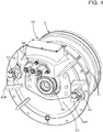
- FIG. 1 is a perspective view illustrating the motor generator 34 taken out from the power transmission mechanism of FIG. 7 .
- FIG. 2 is a perspective view explaining the cooling structure of the motor generator 34.
- FIG. 3 (A) shows an upper surface view of the piping connecting portion 40
- FIG. 3 (B) shows a side surface view of the piping connecting portion 40.
- FIG. 4 shows a view illustrating a cross section taken along a line A-A of FIG. 3 (A) . As shown in FIG.
- an inverter device is electrically connected to the stator wiring by a socket 39 of a terminal board 38, the stator wiring being arranged inside the motor generator 34.
- a cooling liquid pump is connected to the cooling liquid pipe by the piping connecting portion 40, the cooling liquid pipe being arranged inside the motor generator 34.
- the motor generator (the motor) 34 is arranged inside the motor case C.
- the motor case C includes a tubular portion C1 and an end surface portion C2, the tubular portion C1 being provided so as to surround the outer circumference of the motor generator 34, the end surface portion C2 being provided at an end portion of the tubular portion C1 on the hydraulic pump 35 side.
- FIG. 2 shows a perspective view (partly an exploded perspective view) illustrating the stator side of the motor generator 34 from which the motor case C is removed and the structures other than the cooling structure on the stator side is virtually removed from the state shown in FIG. 1 . Referring to FIG. 2 , the stator of the motor generator 34 will be described.
- the motor generator 34 includes at least a water jacket 52 and winding (not shown in the drawings), a stator 54A thermal conductor 55, and a motor housing 56.
- a stator 54 having an annular shape is provided on the inner circumference of the water jacket 52.
- the stator 54 has a plurality of teeth 54B.
- the winding is wound around each of the teeth 54B.
- the thermal conductor 55 is provided along the inner peripheral surface 52B of the water jacket 52 and covers the winding and the stator 54.
- the water jacket 52 is mounted inside the motor housing 56.
- the rotating shaft 36 is disposed inside the stator 54A and a cylindrical rotor (not shown in the drawings) having a permanent magnet embedded therein is disposed inside the stator 54.
- the plurality of teeth 54B are arranged in the circumferential direction, the teeth 54B protruding toward the inner circumference side of the yoke 54A having an annular shape.
- Each of the teeth 54B has a spreading shape, and the winding is wound around the body portion thereof with an insulating member interposed therebetween.
- the thermal conductor 55 is molded with a resin having a high thermal conductivity on the whole of the stator 54, leaving the teeth 54B and the radially-inner end of the winding.
- the motor housing 56 is formed of an iron-based casting such as the FC (referred to as a gray cast iron (also referred to as a regular cast iron)), the FCD (referred to as a ductile cast iron) or the like.
- FC referred to as a gray cast iron (also referred to as a regular cast iron)
- FCD referred to as a ductile cast iron
- the water jacket 52 is formed of an aluminum alloy having a high thermal conductivity and formed to have an annular shape.
- a jacket passage 52A is formed inside the water jacket 52 in the circumferential direction, the jacket passage 52A having a zigzag shape.
- the jacket passage 52A includes a straight hole A1, a communication groove A2, and a communication groove A3.
- the communication groove A2 and the communication groove A3 are respectively provided on both end faces of the water jacket 52 in the axial direction of the rotating shaft 36, and connect the adjacent straight holes A1 each other at both end faces.
- the straight holes A1 are provided inside the water jacket 52, and are formed by perforating a plurality of holes (a plurality of holes passages) in the circumferential direction of the water jacket 52 and in parallel with the axial direction of the rotating shaft 36.
- the communication groove A2 is communicated with the adjacent straight holes A1 at one end surface of the water jacket 52 (at a front surface side of the sheet of FIG. 2 ), and the communication groove A3 is communicated with the adjacent linear holes A1 at the other end surface of the water jacket 52 (at a back surface side of the sheet of FIG. 2 ).
- the communication groove A2 and the communication groove A3 are closed by sealing members 62 each having an annular shape, the sealing members 62 being arranged on both of the end faces of the water jacket 52 in the axial direction of the rotating shaft 36.
- the jacket passage 52A is formed in a width extending over both of the end surfaces of the water jacket 52 in the axial direction of the rotating shaft 36.
- At least one cooling liquid supplying port A4 and at least one cooling liquid outputting port A5 are provided in the jacket passage 52A.
- one communication groove A2 (on the right side in FIG. 2 ) constituting the jacket passage 52A serves as a cooling liquid supplying port A4, and another communication groove A2 (on the left side in FIG. 2 ) serves as a cooling liquid outputting port A5.
- a hole 62A is provided at a position corresponding to the cooling liquid supplying port A4 and the cooling liquid outputting port A5, the hole 62A being used for forming the cooling liquid passage.
- the cooling liquid supplying port A4 and the cooling liquid outputting port A5 may be reversely provided or may be another communicating groove A2 or another communicating groove A3.
- the cooling liquid supplying port A4 and the cooling liquid outputting port A5 are connected to a circulation device (a cooling liquid pump) by the piping connection portion 40, the circulation device being provided outside the motor generator 34. With the circulation device, a liquid coolant such as water or fluid circulates through the jacket passage 52A.
- the cooling liquid supplying port A4 is connected to the internal tube 41P.
- the internal tube 41P is connected to the external tube 42P by the piping connecting portion 40.
- the cooling liquid outputting port A5 is connected to the internal tube 41P.
- the internal tube 41P is connected to the external tube 42P by the piping connecting portion 40.
- the motor generator 34 according to the present embodiment is characterized in including the piping connecting portion 40. Prior to the explanation of the piping connecting portion 40, the circulation of the cooling liquid in the cooling structure of the motor generator 34 will be described with reference to FIG. 2 .
- the cooling liquid outputted from the cooling liquid pump passes through the external tube 42P provided on the side of the cooling liquid supplying port A4, the piping connecting portion 40, and the internal tube 41P and then reaches the cooling liquid supplying port A4.
- the cooling liquid reaches the communication groove A3 from the cooling liquid supplying port A4 through the straight hole A1, further reaches the communication groove A2 through another straight hole A1, and then finally reaches the cooling liquid outputting port A5 through further another straight hole A1.
- the cooling liquid that has reached the cooling liquid outputting port A5 reaches the cooling liquid pump through the internal tube 41P provided on the side of the cooling liquid outputting port A5, the piping connecting portion 40, and the external tube 42P.
- the cooling liquid flows from the cooling liquid supplying port A4 separately into the straight hole A1 arranged on the upper side in FIG. 2 and into the straight hole A1 arranged on the lower side in FIG. 2 ; however, the embodiment is not limited to that.
- the cooling liquid flowing from the cooling liquid supplying port A4 to the straight hole A1 on the upper side flows through the straight holes A1 arranged in the upper half of the water jacket 52, the communication groove A2, and the communication groove A3, and thus cools the upper half of the water jacket 52
- the cooling liquid flowing from the cooling liquid supplying port A4 to the straight hole A1 flows through the straight holes A1 arranged in the lower half of the water jacket 52, the communication groove A2, and the communication groove A3, and thus cools the lower half of the water jacket 52.
- the cooling liquids flowing separately in the vertical direction and cooling the water jacket 52 are mixed each other at the cooling liquid outputting port A5.
- the piping connecting portion 40 that the motor generator 34 having the above-mentioned cooling structure includes to connect the external tube 42P and the internal tube 41P each other will be described in detail more.
- FIG. 3(A) and FIG. 3(B) illustrate external views of the piping connecting portion 40.
- FIG. 4 is a cross sectional view taken along the line A-A of FIG. 3 .
- the piping connecting portion 40 is fixed, by a bolt B, to an end surface portion C2 of the motor case C at the flange portion F.
- the piping connecting portion 40 includes a supporting member 50, the supporting member 50 supports the internal tube 41P and the external tube 42P on the same axis so as to allow the internal tube 41P and the external tube 42P to be communicated with each other.
- the supporting member 50 includes a first supporting portion 41 and a second supporting portion 42.
- the first supporting portion 41 is provided on a side of the motor case C and supports the internal tube 41P.
- the second supporting portion 42 is provided on the other side opposite to the motor case C and supports the external tube 42P.
- the first supporting portion 41 includes a plurality of sealing members, an air chamber 46, and a water draining portion 47.
- the plurality of sealing members are provided annularly along the outer circumference surface of the internal tube 41P at intervals in the axial direction of the internal tube 41P.
- the plurality of sealing members include two sealing members, the first sealing member 43 provided on a side of the external tube 42P, the second sealing member 44 provided on a side of the internal tube 41P. Meanwhile, the side of the external tube 42P corresponds to the left side in FIG. 4 , and the side of the internal tube 41P corresponds to the right side in FIG. 4 .
- the first sealing member 43 is provided between the air chamber 46 and the external tube 42P.
- the second sealing member 44 is provided between the air chamber 46 and the motor generator 34.
- Each of the first sealing member 43 and the second sealing member 44 is constituted of an O-ring.
- a wire diameter (a thickness) of the second sealing member 44 is larger than a wire diameter (a thickness) of the first sealing member 43 provided on the side of the external tube 42P.
- the first supporting portion 41 includes an inner portion 41a and an outer portion 41b, the inner portion 41a being provided on a side closer to the internal tube 41P side than to the flange F, the outer portion 41b being provided on a side closer to the external tube 42P than to the flange F.
- the inner portion 41a is fitted into an opening portion C3 that is provided in the end face portion C2 of the motor case C.
- the outer portion 41b protrudes from the opening portion C3 toward a side of the external tube 42P.
- the first supporting portion 41 includes a first concave groove 41A and a second concave groove 41B, the first concave groove 41A being provided in the outer portion 41b, the second concave groove 41B being provided in the inner portion 41a.
- the first concave groove 41A and the second concave groove 41B are provided annularly along the outer circumference surface of the internal tube 41P.
- the first concave groove 41A is formed between a first protrusion 411 and a second protrusion 412, the first protrusion 411 protruding in the inner diameter direction (the direction toward the center of the internal tube 41P) on the side of the external tube 42P, the second protrusion 412 protruding in the inner diameter direction on the side of the internal tube 41P.
- the second concave groove 41B is formed between a third protrusion 413 and a fourth protrusion 414, the third protrusion 413 protruding in the inner diameter direction on the side of the external tube 42P, the fourth protrusion 414 protruding in the inner diameter direction on the side of the internal tube 41P.
- the first protrusion 411, the second protrusion 412, the third protrusion 413, and the fourth protrusion 414 are in contact with the outer circumference surface of the internal tube 41P.
- the first sealing member 43 is arranged in the first groove 41A, and is tightly contacted to the outer circumference surface of the internal tube 41P.
- the second sealing member 44 is arranged in the second concave groove 41B, and is tightly contacted to the outer circumferential surface of the internal tube 41P.
- a distance between the first sealing member 43 and the second sealing member 44 (a distance in the axial direction of the internal tube 41P) is configured to be longer than a length of the second supporting portion 42 (a length in the axial direction of the external tube 42).
- a third sealing member 45 (an O-ring) is provided on a contacting surface between the supporting member 50 and the motor case C.
- the external tube 42P is fitted to the first supporting portion 41 by a commonly-known method, and is supported by the first supporting portion 41 with the waterproofing performance.
- the first sealing member 43 on the side of the external tube 42P sufficiently provides the waterproofing performance with the internal tube 41P, and the leakage from the internal tube 41P can be prevented.
- the second sealing member 44 on the side of the internal tube 41P is capable of preventing the leakage inside the motor generator 34 even when the first sealing member 43 on the side of the external tube 42P wears and leaks the liquid from the internal tube 41P, for example.
- both of the first sealing member 43 on the side of the external tube 42P and the second sealing member 44 on the side of the internal tube 41P support the internal tube 41P with these two sealing members, and thereby the internal tube 41P is supported freely in the radial direction and in the thrust direction.
- the second sealing member 44 provides a buffer function (a vibration absorbing function) with use of the second sealing member 44 provided on the side of the internal tube 41P that has a larger one of the wire diameters, and the waterproofing function is realized by the first sealing member 43 provided on the side of the external tube 42P that has a smaller one of the wire diameters.
- the air chamber 46 is provided annularly along the outer circumference surface of the internal tube 41P.
- the air chamber 46 is provided between the first sealing member 43 and the second sealing member 44. Specifically, the air chamber 46 is separated from the first concave groove 41A by the second protrusion 412, and is separated from the second concave groove 41B by the third protrusion 413.
- an inner diameter of the air chamber 46 is formed to be larger than an inner diameter of the first concave groove 41A and the inner diameter of the second concave groove 41B.
- a width of the air chamber 46 (the length of the internal tube 41P in the axial direction) is formed to be larger than a width of the first concave groove 41A and a width of the second concave groove 41B.
- the inner wall of the air chamber 46 on the side of the external tube 42P is positioned closer to the external tube 42P side than to the flange F.
- the inner wall of the air chamber 46 on the side of the internal tube 41P is positioned closer to the internal tube 41P side than to the flange F.
- the water draining portion 47 communicates the air chamber 46 with the outside of the motor case C.
- the water draining portion 47 includes a hole provided in the first supporting portion 41 so as to connect the air chamber 46 and the outside of the motor generator 34 to each other.
- the water draining portion 47 is provided vertically below or substantially vertically below the air chamber 46 having an annular shape.
- the hole of the water draining portion 47 is inclined downwardly from the internal tube 41P side toward the external tube 42P side, and opens approaching the external tube 42P side from the flange F.
- the air chamber 46 serves as a buffer space for the cooling liquid that has leaked from the internal tube 41P even when the leakage occurs due to the abrasion of the first sealing member 43 on the side of the external tube 42P.
- the position of the water draining portion 47 is provided on the vertically lower side of the air chamber 46 annularly formed such that the cooling liquid leaked from the internal tube 41P and accumulated in the air chamber 46 is drained. In this manner, the cooling liquid accumulated in the air chamber 46 can be drained to the outside of the motor case C (the outside of the motor generator 34) by the gravity.
- the liquid-cooled motor since the liquid-cooled motor includes the piping connection portion having the plurality of sealing members (the O-rings), the vibrations generated in the cooling liquid pipe by the rotation can be well absorbed, and additionally it is possible to provide a liquid-cooled motor with the good waterproofing performance.
- the plurality of first sealing members 43 may be provided on a side closer to the external tube 42P than to the air chamber 46, and the plurality of second sealing members 44 may be provided on a side closer to the internal tube 41P than to the air chamber 46.
Landscapes
- Engineering & Computer Science (AREA)
- Power Engineering (AREA)
- Physics & Mathematics (AREA)
- Geometry (AREA)
- Thermal Sciences (AREA)
- Mechanical Engineering (AREA)
- General Engineering & Computer Science (AREA)
- Motor Or Generator Cooling System (AREA)
- Motor Or Generator Frames (AREA)
Abstract
Description
- The present invention relates to a liquid-cooled motor serving as a driving prime mover and a power generator.
- A rotary electric machine (a motor generator) serving as a driving prime mover and a power generator is installed also in a working machine such as a skid steer loader and a compact track loader in addition to the hybrid automobile. As the motor mentioned above, a permanent magnet motor providing a compact size and a high power is often employed. The permanent magnet motor needs to be prevented from the overheating in order to continue the normal operation. In addition, since the permanent magnet motor requires a large capacity of cooling per unit volume, a highly efficient cooling system is preferable, and a cooling system in which a liquid is circulated is particularly preferable. A motor employing a liquid cooling method (hereinafter referred to as a liquid-cooled motor) includes a stator that forms a magnetic path at equal circumferential intervals, a motor case that is fitted to the outer circumferential surface of the stator, and a cooling liquid passage formed between the outer circumferential surface of the stator and the inner circumferential surface of the motor case. The applicant of the present invention has filed the application of the liquid-cooled motor mentioned above that is a liquid-cooled motor configured to cool the stator and the motor case evenly in the circumferential direction without intervening the magnetic path of the stator (refer to the Patent document 1).
- In the liquid-cooled motor disclosed in
Patent document 1, the stator winding of the stator projects the end portion of the stator winding outward from the left side surface of and the right side surface of the stator, a width of the motor case in the axial center direction is formed to be larger than a width of the stator in the axial center direction so as to cover the end portion of the stator winding, and a liquid-supplying tube having an annular shape is arranged facing the outer circumferential side of the left and right side surfaces of the stator (radially outward from the stator winding) and the end portion of the inner circumferential surface of the motor case in the axial center direction. The liquid-supplying pipe includes an annular pipe portion positioned on the outer circumference of the side surface of the stator and communicating with all of the liquid-flowing tubes and includes at least one communicating pipe connected to the annular pipe portion and having the inside communicating with the annular pipe portion, and the communicating pipe is connected to a pump by a hose or the like, the pump being provided outside the motor (Paragraph [0020] and Paragraph [0021]). - [Patent Document 1] Japanese Unexamined Patent Application Publication No.
2014-230358 - According to the liquid-cooled motor disclosed in
Patent Document 1, it is preferred that the stator and the motor case can be cooled evenly in the circumferential direction without intervening the magnetic path of the stator. Meanwhile, in the liquid-cooled motor, it is required to connect the cooling liquid pipe to a hose or the like provided outside the motor as described above, the cooling liquid pipe being provided inside the motor. The connection structure includes: (1) a structure in which the cooling liquid pipe is drawn out to the outside of the motor and additionally the coupling attached to the cooling liquid pipe is directly connected to the flexible piping that is an external piping; and (2) the structure in which the flexible piping is connected to the motor case and additionally connected to the external piping via the wall surface of the motor case. In each of the connection structures, it is required to have a configuration to absorb vibrations in the radial direction or vibrations in the thrust direction, the vibrations being received by the cooling liquid pipe arranged inside the motor due to the motor rotation, in addition to a configuration to prevent the cooling liquid from leaking inside the motor (to provide a waterproofing performance). Since the vibrations of the cooling liquid pipe is different from the vibrations generated in the motor case itself, it is required in the liquid-cooled motor to have a configuration to absorb the vibrations received by the cooling liquid pipe arranged inside the motor in addition to a configuration to absorb the vibrations of the motor case itself. Thus, it is preferable to absorb the vibrations generated between the cooling liquid pipe and the motor case by the connection structure (a piping adapter) attached to the motor case. - The present invention is provided to solve the problems of the conventional technique described above, and intends to provide a liquid-cooled motor configured to absorb the vibrations generated in a cooling liquid pipe due to motor rotations and configured to have a better waterproofing performance.
- Technical means employed by the present invention in order to solve the technical problems are as follows.
- A liquid-cooled motor includes a motor case, a motor arranged inside the motor case, an internal tube in which cooling liquid flows, the internal tube being arranged inside the motor case, an external tube in which the cooling liquid flows, the external tube being arranged outside the motor case, and a supporting member fixed to the motor case, the supporting member supporting the internal tube and the external tube and allowing the internal tube and the external tube to be communicated with each other, wherein the supporting member includes a first supporting portion arranged to a side of the motor case, the first supporting portion supporting the internal tube, and a second supporting portion arranged to another side opposite to the side of the motor case, the second supporting portion supporting the external tube, and wherein the first supporting portion includes a plurality of sealing members circularly arranged along an outer circumference surface of the internal tube at intervals in a direction of an axial of the internal tube, an air chamber arranged between the plurality of the sealing members, and a water draining portion allowing the air chamber and an outside portion of the motor case to be communicated with each other.
- The air chamber is circularly arranged along the outer circumference surface of the internal tube, the plurality of sealing members include a first sealing member arranged between the air chamber and the external tube and a second sealing member arranged between the air chamber and the motor, and the second sealing member has a wire diameter larger than another wire diameter of the first sealing member.
- A liquid-cooled motor is provided according to the present invention, the liquid-cooled motor being configured to satisfactorily absorb the vibrations generated in a cooling liquid pipe due to motor rotations and configured to have a better waterproofing performance.
-
-
FIG. 1 is a perspective view illustrating a liquid-cooled motor according to embodiment of the present invention. -
FIG. 2 is a perspective view explaining a cooling structure of the liquid-cooled motor according to the embodiment of the present invention. -
FIG. 3 is a view illustrating an upper surface of a piping connecting portion ofFIG. 1 andFIG. 2 in (A) and illustrating a side surface of the piping connecting portion in (B). -
FIG. 4 is a view illustrating an A-A cross section of (A) shown inFIG. 3 . -
FIG. 5 is a side view illustrating a track loader that is one example of working machines according to the embodiment. -
FIG. 6 is a side view illustrating a part of the track loader lifting up a cabin according to the embodiment. -
FIG. 7 is a perspective view illustrating a schematic arrangement of a power transmission mechanism of the track loader according to the embodiment. - Referring to the drawings, a preferred embodiment of a liquid-cooled motor and a piping connecting portion included in the liquid-cooled motor according to the present invention will be described below, exemplifying a working machine on which the liquid-cooled motor is mounted. In addition, the liquid-cooled motor according to the present invention includes a motor generator.
- The overall configuration of the working machine will be described at first.
- As shown in
FIG. 5 andFIG. 6 , theworking machine 1 according to the present invention includes amachine body 2, a working device 3 mounted on themachine body 2, and a traveling device 4 configured to support themachine body 2.FIG. 5 andFIG. 6 illustrate a track loader as an example of the working machine; however, the working machine on which the liquid-cooled motor according to the present invention is mounted is not limited to the track loader and may be a tractor, a skid steer loader, a compact track loader, a backhoe, or the like. In explanations of the embodiment of the present invention, a front side of an operator seated on an operator seat of the working machine (the left side ofFIG. 5 ) is referred to as the front, a rear side of the operator (the right side ofFIG. 5 ) is referred to as the rear, a left side of the operator (a front surface side of the sheet ofFIG. 5 ) is referred to as the left, and a right side of the operator (a back surface side of the sheet ofFIG. 5 ) is referred to as the right. - A
cabin 5 is mounted on a front portion of an upper portion of themachine body 2. A rear portion of thecabin 5 is supported by the supportingbracket 11 of themachine body 2 so as to be swingable about the supportingshaft 12. A front portion of thecabin 5 is configured to be mounted on the front portion of themachine body 2. - An
operator seat 13 is installed inside thecabin 5. On one side (for example, the left side) of theoperator seat 13, atraveling operation device 14 configured to operate the traveling device 4 is arranged. - The traveling device 4 is constituted of a crawler type traveling device. The traveling device 4 is arranged under the left side of the
machine body 2 and under the right side of themachine body 2. The traveling device 4 includes a first travelingportion 21L and a second travelingportion 21R each configured to be activated to be driven by a hydraulic pressure, and is configured to travel with use of the first travelingportion 21L and the second travelingportion 21R. - The working device 3 includes a
boom 22L, aboom 22R, and a bucket 23 (a working tool). Theboom 22L is arranged on the left side of themachine body 2. Theboom 22R is arranged on the right side of themachine body 2. Theboom 22L and theboom 22R are coupled to each other by a coupling body. Theboom 22L and theboom 22R are supported by thefirst lift link 24 and thesecond lift link 25. Alift cylinder 26 constituted of a double acting hydraulic cylinder is provided between a base portion sides of theboom 22L and theboom 22R and a rear lower portion of themachine body 2. Simultaneously extending and shortening thelift cylinder 26, theboom 22L and theboom 22R are swung up and down.Attachment brackets 27 are respectively supported pivotally on the tip end sides of theboom 22L and theboom 22R so as to be turned about a lateral axis, and the back surface side of thebucket 23 is attached to theattachment brackets 27 provided on the left and the right. - A
tilt cylinder 28 constituted of a double acting hydraulic cylinder is provided between theattachment brackets 27 and the middle portions of theboom 22L and theboom 22R, the middle portions being close to the tip end side of theboom 22L and theboom 22R. Thetilt cylinder 28 is extended and shortened, and thereby thebucket 23 is swung (a shoveling operation / a dumping operation). - The
bucket 23 is configured to be attachable to and detachable from theattachment bracket 27. When thebucket 23 is removed and the various types of attachments (the hydraulically-driven working tools having a hydraulic actuator to be described later) are attached to theattachment bracket 27, that configuration allows various types of working operations other than the excavation (or another excavating operation). Aprime mover 29 is provided on the rear side of the machine body. Theprime mover 29 is an engine. Meanwhile, it should be noted that theprime mover 29 may be an electric motor (a motor generator), or may include both of the engine and the electric motor, and theprime mover 29 having both of them will be described below in the following explanation. In addition, a tank (a hydraulic fluid tank) 31 configured to store a hydraulic fluid is provided on themachine body 2. - The liquid-cooled motor according to the embodiment of the present invention constitutes a power transmission mechanism of the working
machine 1. In the explanation of the embodiment, the power transmission mechanism has a parallel hybrid configuration. Referring to a perspective view (FIG. 7 ) illustrating a schematic arrangement of the power transmission mechanism, an outline of the power transmission mechanism will be described below, the power transmission mechanism including amotor generator 34 that is a motor constituting the liquid-cooled motor according to the embodiment of the present invention. - As shown in
FIG. 7 , the power transmission mechanism includes at least anengine 32, aflywheel 33, and themotor generator 34. The power transmission mechanism transmits the power of theengine 32 and the power of themotor generator 34 to thehydraulic pump 35 in an alternative manner or in a combination manner, thehydraulic pump 35 being an example of a driven machine. - The
engine 32 is constituted of a diesel engine, a gasoline engine or the like. The crankshaft of theengine 32 protrudes toward thehydraulic pump 35 side, and aflywheel 33 is connected to the tip end of the crankshaft (on thehydraulic pump 35 side). - The
flywheel 33 is formed of a material having a substantially-disk shape and having a large mass (for example, a metal such as a cast iron). A crankshaft of theengine 32 is connected to the center of theflywheel 33. Theflywheel 33 is surrounded by a flywheel housing. - The
motor generator 34 is arranged on theflywheel 33 and on thehydraulic pump 35 side. Themotor generator 34 has a rotor (rotator) and a stator. As themotor generator 34, a three-phase AC synchronous motor having an embedded permanent magnet is preferably employed, however another type of synchronous motor may be employed. - When the
motor generator 34 functions serving as an electric generator (a generator), the rotor receives a rotational power of theflywheel 33. On the other hand, when the motor generator 4 functions serving as an electric motor (a motor), the rotor applies a rotational power to theflywheel 33. That is, themotor generator 34 receives the rotational power through theflywheel 33. - The
hydraulic pump 35 serving as the driven machine is driven by receiving the power applied from theengine 32 and/or themotor generator 34. Specifically, a hydraulic pump for a hydrostatic transmission can be exemplified as thehydraulic pump 35. - In the power transmission mechanism of the working
machine 1 having the above-mentioned schematic arrangement, themotor generator 34 includes a cooling structure inside, themotor generator 34 being the motor constituting the liquid-cooled motor according to the embodiment of the present invention, and includes apiping connecting portion 40 serving as a piping adapter configured to connect the cooling structure arranged inside and the cooling pipe arranged outside (anexternal tube 42P) to each other. In the description of themotor generator 34 that is a motor constituting the liquid-cooled motor according to the embodiment of the present invention, themotor generator 34 is less related to thepiping connecting portion 40 that is a technical feature of the embodiment of the present invention, and thus the configuration of themotor generator 34 will not described below. - Next, the cooling structure and the
piping connecting portion 40 included in themotor generator 34 will be described more in detail, themotor generator 34 being a motor constituting the liquid-cooled motor arranged at the above-mentioned position according to the embodiment of the present invention.FIG. 1 is a perspective view illustrating themotor generator 34 taken out from the power transmission mechanism ofFIG. 7 .FIG. 2 is a perspective view explaining the cooling structure of themotor generator 34.FIG. 3 (A) shows an upper surface view of thepiping connecting portion 40, andFIG. 3 (B) shows a side surface view of thepiping connecting portion 40.FIG. 4 shows a view illustrating a cross section taken along a line A-A ofFIG. 3 (A) . As shown inFIG. 1 , an inverter device is electrically connected to the stator wiring by asocket 39 of aterminal board 38, the stator wiring being arranged inside themotor generator 34. In addition, as in the following explanations, a cooling liquid pump is connected to the cooling liquid pipe by thepiping connecting portion 40, the cooling liquid pipe being arranged inside themotor generator 34. When therotating shaft 36 of themotor generator 34 rotates, the cooling liquid pipe inside the motor receives the vibrations generated in the radial direction or the vibrations generated in the thrust direction. - As shown in
FIG. 1 , the motor generator (the motor) 34 is arranged inside the motor case C. The motor case C includes a tubular portion C1 and an end surface portion C2, the tubular portion C1 being provided so as to surround the outer circumference of themotor generator 34, the end surface portion C2 being provided at an end portion of the tubular portion C1 on thehydraulic pump 35 side.FIG. 2 shows a perspective view (partly an exploded perspective view) illustrating the stator side of themotor generator 34 from which the motor case C is removed and the structures other than the cooling structure on the stator side is virtually removed from the state shown inFIG. 1 . Referring toFIG. 2 , the stator of themotor generator 34 will be described. - The
motor generator 34 includes at least awater jacket 52 and winding (not shown in the drawings), astator 54Athermal conductor 55, and amotor housing 56. Astator 54 having an annular shape is provided on the inner circumference of thewater jacket 52. Thestator 54 has a plurality ofteeth 54B. The winding is wound around each of theteeth 54B. Thethermal conductor 55 is provided along the innerperipheral surface 52B of thewater jacket 52 and covers the winding and thestator 54. Thewater jacket 52 is mounted inside themotor housing 56. The rotatingshaft 36 is disposed inside thestator 54A and a cylindrical rotor (not shown in the drawings) having a permanent magnet embedded therein is disposed inside thestator 54. - In the
stator 54, the plurality ofteeth 54B are arranged in the circumferential direction, theteeth 54B protruding toward the inner circumference side of theyoke 54A having an annular shape. Each of theteeth 54B has a spreading shape, and the winding is wound around the body portion thereof with an insulating member interposed therebetween. Thethermal conductor 55 is molded with a resin having a high thermal conductivity on the whole of thestator 54, leaving theteeth 54B and the radially-inner end of the winding. - The
motor housing 56 is formed of an iron-based casting such as the FC (referred to as a gray cast iron (also referred to as a regular cast iron)), the FCD (referred to as a ductile cast iron) or the like. Themotor housing 56 is fitted and mounted on the outer circumference of thewater jacket 52 separately formed. - The
water jacket 52 is formed of an aluminum alloy having a high thermal conductivity and formed to have an annular shape. Ajacket passage 52A is formed inside thewater jacket 52 in the circumferential direction, thejacket passage 52A having a zigzag shape. Thejacket passage 52A includes a straight hole A1, a communication groove A2, and a communication groove A3. The communication groove A2 and the communication groove A3 are respectively provided on both end faces of thewater jacket 52 in the axial direction of therotating shaft 36, and connect the adjacent straight holes A1 each other at both end faces. The straight holes A1 are provided inside thewater jacket 52, and are formed by perforating a plurality of holes (a plurality of holes passages) in the circumferential direction of thewater jacket 52 and in parallel with the axial direction of therotating shaft 36. - The communication groove A2 is communicated with the adjacent straight holes A1 at one end surface of the water jacket 52 (at a front surface side of the sheet of
FIG. 2 ), and the communication groove A3 is communicated with the adjacent linear holes A1 at the other end surface of the water jacket 52 (at a back surface side of the sheet ofFIG. 2 ). The communication groove A2 and the communication groove A3 are closed by sealingmembers 62 each having an annular shape, the sealingmembers 62 being arranged on both of the end faces of thewater jacket 52 in the axial direction of therotating shaft 36. In this manner, thejacket passage 52A is formed in a width extending over both of the end surfaces of thewater jacket 52 in the axial direction of therotating shaft 36. - In order to circulate the cooling liquid in the
jacket passage 52A configured as described above, at least one cooling liquid supplying port A4 and at least one cooling liquid outputting port A5 are provided in thejacket passage 52A. Here, one communication groove A2 (on the right side inFIG. 2 ) constituting thejacket passage 52A serves as a cooling liquid supplying port A4, and another communication groove A2 (on the left side inFIG. 2 ) serves as a cooling liquid outputting port A5. Here, in the sealingmember 62 having an annular shape, ahole 62A is provided at a position corresponding to the cooling liquid supplying port A4 and the cooling liquid outputting port A5, thehole 62A being used for forming the cooling liquid passage. Meanwhile, the cooling liquid supplying port A4 and the cooling liquid outputting port A5 may be reversely provided or may be another communicating groove A2 or another communicating groove A3. - The cooling liquid supplying port A4 and the cooling liquid outputting port A5 are connected to a circulation device (a cooling liquid pump) by the
piping connection portion 40, the circulation device being provided outside themotor generator 34. With the circulation device, a liquid coolant such as water or fluid circulates through thejacket passage 52A. - The cooling liquid supplying port A4 is connected to the
internal tube 41P. Theinternal tube 41P is connected to theexternal tube 42P by thepiping connecting portion 40. The cooling liquid outputting port A5 is connected to theinternal tube 41P. Theinternal tube 41P is connected to theexternal tube 42P by thepiping connecting portion 40. Themotor generator 34 according to the present embodiment is characterized in including thepiping connecting portion 40. Prior to the explanation of thepiping connecting portion 40, the circulation of the cooling liquid in the cooling structure of themotor generator 34 will be described with reference toFIG. 2 . - As shown by a black arrowed line in
FIG. 2 , the cooling liquid outputted from the cooling liquid pump passes through theexternal tube 42P provided on the side of the cooling liquid supplying port A4, thepiping connecting portion 40, and theinternal tube 41P and then reaches the cooling liquid supplying port A4. The cooling liquid reaches the communication groove A3 from the cooling liquid supplying port A4 through the straight hole A1, further reaches the communication groove A2 through another straight hole A1, and then finally reaches the cooling liquid outputting port A5 through further another straight hole A1. The cooling liquid that has reached the cooling liquid outputting port A5 reaches the cooling liquid pump through theinternal tube 41P provided on the side of the cooling liquid outputting port A5, thepiping connecting portion 40, and theexternal tube 42P. - In that case, the cooling liquid flows from the cooling liquid supplying port A4 separately into the straight hole A1 arranged on the upper side in
FIG. 2 and into the straight hole A1 arranged on the lower side inFIG. 2 ; however, the embodiment is not limited to that. The cooling liquid flowing from the cooling liquid supplying port A4 to the straight hole A1 on the upper side flows through the straight holes A1 arranged in the upper half of thewater jacket 52, the communication groove A2, and the communication groove A3, and thus cools the upper half of thewater jacket 52, and the cooling liquid flowing from the cooling liquid supplying port A4 to the straight hole A1 flows through the straight holes A1 arranged in the lower half of thewater jacket 52, the communication groove A2, and the communication groove A3, and thus cools the lower half of thewater jacket 52. The cooling liquids flowing separately in the vertical direction and cooling thewater jacket 52 are mixed each other at the cooling liquid outputting port A5. - The
piping connecting portion 40 that themotor generator 34 having the above-mentioned cooling structure includes to connect theexternal tube 42P and theinternal tube 41P each other will be described in detail more. -
FIG. 3(A) and FIG. 3(B) illustrate external views of thepiping connecting portion 40.FIG. 4 is a cross sectional view taken along the line A-A ofFIG. 3 . As shown inFIG. 3 andFIG. 4 , thepiping connecting portion 40 is fixed, by a bolt B, to an end surface portion C2 of the motor case C at the flange portion F. Thepiping connecting portion 40 includes a supportingmember 50, the supportingmember 50 supports theinternal tube 41P and theexternal tube 42P on the same axis so as to allow theinternal tube 41P and theexternal tube 42P to be communicated with each other. Further, the supportingmember 50 includes a first supportingportion 41 and a second supportingportion 42. The first supportingportion 41 is provided on a side of the motor case C and supports theinternal tube 41P. The second supportingportion 42 is provided on the other side opposite to the motor case C and supports theexternal tube 42P. The first supportingportion 41 includes a plurality of sealing members, anair chamber 46, and awater draining portion 47. The plurality of sealing members are provided annularly along the outer circumference surface of theinternal tube 41P at intervals in the axial direction of theinternal tube 41P. - In the present embodiment, the plurality of sealing members include two sealing members, the first sealing
member 43 provided on a side of theexternal tube 42P, the second sealingmember 44 provided on a side of theinternal tube 41P. Meanwhile, the side of theexternal tube 42P corresponds to the left side inFIG. 4 , and the side of theinternal tube 41P corresponds to the right side inFIG. 4 . Thefirst sealing member 43 is provided between theair chamber 46 and theexternal tube 42P. Thesecond sealing member 44 is provided between theair chamber 46 and themotor generator 34. Each of the first sealingmember 43 and the second sealingmember 44 is constituted of an O-ring. Preferably, a wire diameter (a thickness) of the second sealingmember 44 is larger than a wire diameter (a thickness) of the first sealingmember 43 provided on the side of theexternal tube 42P. - The first supporting
portion 41 includes aninner portion 41a and anouter portion 41b, theinner portion 41a being provided on a side closer to theinternal tube 41P side than to the flange F, theouter portion 41b being provided on a side closer to theexternal tube 42P than to the flange F. Theinner portion 41a is fitted into an opening portion C3 that is provided in the end face portion C2 of the motor case C. Theouter portion 41b protrudes from the opening portion C3 toward a side of theexternal tube 42P. The first supportingportion 41 includes a firstconcave groove 41A and a secondconcave groove 41B, the firstconcave groove 41A being provided in theouter portion 41b, the secondconcave groove 41B being provided in theinner portion 41a. The firstconcave groove 41A and the secondconcave groove 41B are provided annularly along the outer circumference surface of theinternal tube 41P. Specifically, the firstconcave groove 41A is formed between afirst protrusion 411 and asecond protrusion 412, thefirst protrusion 411 protruding in the inner diameter direction (the direction toward the center of theinternal tube 41P) on the side of theexternal tube 42P, thesecond protrusion 412 protruding in the inner diameter direction on the side of theinternal tube 41P. The secondconcave groove 41B is formed between athird protrusion 413 and afourth protrusion 414, thethird protrusion 413 protruding in the inner diameter direction on the side of theexternal tube 42P, thefourth protrusion 414 protruding in the inner diameter direction on the side of theinternal tube 41P. Thefirst protrusion 411, thesecond protrusion 412, thethird protrusion 413, and thefourth protrusion 414 are in contact with the outer circumference surface of theinternal tube 41P. - The
first sealing member 43 is arranged in thefirst groove 41A, and is tightly contacted to the outer circumference surface of theinternal tube 41P. Thesecond sealing member 44 is arranged in the secondconcave groove 41B, and is tightly contacted to the outer circumferential surface of theinternal tube 41P. In the embodiment, a distance between the first sealingmember 43 and the second sealing member 44 (a distance in the axial direction of theinternal tube 41P) is configured to be longer than a length of the second supporting portion 42 (a length in the axial direction of the external tube 42). - Meanwhile, in order to realize the waterproofing performance in fixing the supporting
member 50 to the motor case C with the bolt B, a third sealing member 45 (an O-ring) is provided on a contacting surface between the supportingmember 50 and the motor case C. In addition, theexternal tube 42P is fitted to the first supportingportion 41 by a commonly-known method, and is supported by the first supportingportion 41 with the waterproofing performance. - Meanwhile, the first sealing
member 43 on the side of theexternal tube 42P sufficiently provides the waterproofing performance with theinternal tube 41P, and the leakage from theinternal tube 41P can be prevented. And, the second sealingmember 44 on the side of theinternal tube 41P is capable of preventing the leakage inside themotor generator 34 even when the first sealingmember 43 on the side of theexternal tube 42P wears and leaks the liquid from theinternal tube 41P, for example. Furthermore, in addition to realizing the waterproofing performance, both of the first sealingmember 43 on the side of theexternal tube 42P and the second sealingmember 44 on the side of theinternal tube 41P support theinternal tube 41P with these two sealing members, and thereby theinternal tube 41P is supported freely in the radial direction and in the thrust direction. In this manner, it is possible to absorb vibrations that are generated between the cooling liquid pipe (theinternal tube 41P) and the motor case C because of the rotations of themotor generator 34. In particular, the wire diameters of the two sealing members are varied, the second sealingmember 44 provides a buffer function (a vibration absorbing function) with use of the second sealingmember 44 provided on the side of theinternal tube 41P that has a larger one of the wire diameters, and the waterproofing function is realized by the first sealingmember 43 provided on the side of theexternal tube 42P that has a smaller one of the wire diameters. - The
air chamber 46 is provided annularly along the outer circumference surface of theinternal tube 41P. Theair chamber 46 is provided between the first sealingmember 43 and the second sealingmember 44. Specifically, theair chamber 46 is separated from the firstconcave groove 41A by thesecond protrusion 412, and is separated from the secondconcave groove 41B by thethird protrusion 413. In the embodiment, an inner diameter of theair chamber 46 is formed to be larger than an inner diameter of the firstconcave groove 41A and the inner diameter of the secondconcave groove 41B. In addition, a width of the air chamber 46 (the length of theinternal tube 41P in the axial direction) is formed to be larger than a width of the firstconcave groove 41A and a width of the secondconcave groove 41B. The inner wall of theair chamber 46 on the side of theexternal tube 42P is positioned closer to theexternal tube 42P side than to the flange F. The inner wall of theair chamber 46 on the side of theinternal tube 41P is positioned closer to theinternal tube 41P side than to the flange F. - The
water draining portion 47 communicates theair chamber 46 with the outside of the motor case C. Specifically, thewater draining portion 47 includes a hole provided in the first supportingportion 41 so as to connect theair chamber 46 and the outside of themotor generator 34 to each other. Thewater draining portion 47 is provided vertically below or substantially vertically below theair chamber 46 having an annular shape. In the embodiment, the hole of thewater draining portion 47 is inclined downwardly from theinternal tube 41P side toward theexternal tube 42P side, and opens approaching theexternal tube 42P side from the flange F. Theair chamber 46 serves as a buffer space for the cooling liquid that has leaked from theinternal tube 41P even when the leakage occurs due to the abrasion of the first sealingmember 43 on the side of theexternal tube 42P. In this manner, it is possible to prevent the cooling liquid from directly leaking into the motor case C. In addition, the position of thewater draining portion 47 is provided on the vertically lower side of theair chamber 46 annularly formed such that the cooling liquid leaked from theinternal tube 41P and accumulated in theair chamber 46 is drained. In this manner, the cooling liquid accumulated in theair chamber 46 can be drained to the outside of the motor case C (the outside of the motor generator 34) by the gravity. - As described above, according to the liquid-cooled motor according to the present embodiment, since the liquid-cooled motor includes the piping connection portion having the plurality of sealing members (the O-rings), the vibrations generated in the cooling liquid pipe by the rotation can be well absorbed, and additionally it is possible to provide a liquid-cooled motor with the good waterproofing performance.
- In the above description, the embodiment of the present invention has been explained. However, all the features of the embodiment disclosed in this application should be considered just as examples, and the embodiment does not restrict the present invention accordingly. A scope of the present invention is shown not in the above-described embodiment but in claims, and is intended to include all modifications within and equivalent to a scope of the claims.
- For example, the plurality of
first sealing members 43 may be provided on a side closer to theexternal tube 42P than to theair chamber 46, and the plurality ofsecond sealing members 44 may be provided on a side closer to theinternal tube 41P than to theair chamber 46. -
- 34
- Motor generator (Motor)
- 41
- First supporting portion
- 41P
- Internal tube
- 42
- Second supporting portion
- 42P
- External tube
- 43
- First sealing member
- 44
- Second sealing member
- 46
- Air chamber
- 47
- Water draining portion
- 50
- Supporting member
- C
- Motor case
Claims (2)
- A liquid-cooled motor comprising:a motor case;a motor arranged inside the motor case;an internal tube in which cooling liquid flows, the internal tube being arranged inside the motor case;an external tube in which the cooling liquid flows, the external tube being arranged outside the motor case; anda supporting member fixed to the motor case, the supporting member supporting the internal tube and the external tube and allowing the internal tube and the external tube to be communicated with each other,wherein the supporting member includes:a first supporting portion arranged to a side of the motor case, the first supporting portion supporting the internal tube; anda second supporting portion arranged to another side opposite to the side of the motor case, the second supporting portion supporting the external tube,and wherein the first supporting portion includes:a plurality of sealing members circularly arranged along an outer circumference surface of the internal tube at intervals in a direction of an axial of the internal tube;an air chamber arranged between the plurality of the sealing members; anda water draining portion allowing the air chamber and an outside portion of the motor case to be communicated with each other.
- The liquid-cooled motor according to claim 1,
wherein the air chamber is circularly arranged along the outer circumference surface of the internal tube,
wherein the plurality of sealing members include:a first sealing member arranged between the air chamber and the external tube; anda second sealing member arranged between the air chamber and the motor, and wherein the second sealing member has a wire diameter larger than another wire diameter of the first sealing member.
Applications Claiming Priority (2)
| Application Number | Priority Date | Filing Date | Title |
|---|---|---|---|
| JP2015252269A JP6470676B2 (en) | 2015-12-24 | 2015-12-24 | Liquid cooling motor |
| PCT/JP2016/085772 WO2017110408A1 (en) | 2015-12-24 | 2016-12-01 | Liquid-cooled motor |
Publications (3)
| Publication Number | Publication Date |
|---|---|
| EP3396819A1 true EP3396819A1 (en) | 2018-10-31 |
| EP3396819A4 EP3396819A4 (en) | 2019-06-19 |
| EP3396819B1 EP3396819B1 (en) | 2020-03-18 |
Family
ID=59090444
Family Applications (1)
| Application Number | Title | Priority Date | Filing Date |
|---|---|---|---|
| EP16878301.7A Active EP3396819B1 (en) | 2015-12-24 | 2016-12-01 | Liquid-cooled motor |
Country Status (4)
| Country | Link |
|---|---|
| US (1) | US10608495B2 (en) |
| EP (1) | EP3396819B1 (en) |
| JP (1) | JP6470676B2 (en) |
| WO (1) | WO2017110408A1 (en) |
Cited By (1)
| Publication number | Priority date | Publication date | Assignee | Title |
|---|---|---|---|---|
| EP4220912A1 (en) * | 2022-01-28 | 2023-08-02 | Etel S.A. | Cooling cage assembly for a rotary electric motor |
Families Citing this family (10)
| Publication number | Priority date | Publication date | Assignee | Title |
|---|---|---|---|---|
| FR3091069A1 (en) * | 2018-12-20 | 2020-06-26 | Valeo Equipements Electriques Moteur | Assembly comprising a rotary electrical machine provided with a cooling chamber and housed inside an enclosure delimited by a clutch bell |
| CN112467940B (en) * | 2019-12-24 | 2022-11-25 | 长城汽车股份有限公司 | Motor cooling structure, drive assembly and vehicle |
| JP7488661B2 (en) * | 2020-02-03 | 2024-05-22 | ヤマハ発動機株式会社 | Housing and rotating electric machine including same |
| FR3113446B1 (en) * | 2020-08-12 | 2023-09-08 | Thermodyn | System comprising a cooling device for a machine enclosed in a pressure casing |
| CN112928856B (en) * | 2021-03-16 | 2025-04-29 | 浙江三新科技有限公司 | A fully enclosed motor with stable internal pressure |
| WO2022253498A1 (en) * | 2021-05-31 | 2022-12-08 | Bernward Welschof | Turas drive and tracked vehicle with turas drive |
| US12149154B2 (en) | 2021-07-22 | 2024-11-19 | General Electric Company | Electric machine having a hybrid insulative-conductive manifold |
| DE102021208196A1 (en) * | 2021-07-29 | 2023-02-02 | Robert Bosch Gesellschaft mit beschränkter Haftung | Stator assembly and method of manufacturing a stator assembly |
| DE102022110820A1 (en) * | 2022-05-03 | 2023-11-09 | Bayerische Motoren Werke Aktiengesellschaft | Electric traction machine for a motor vehicle |
| JP2025090167A (en) * | 2023-12-05 | 2025-06-17 | トヨタ自動車株式会社 | Motor |
Family Cites Families (6)
| Publication number | Priority date | Publication date | Assignee | Title |
|---|---|---|---|---|
| JPS62178139A (en) * | 1986-01-30 | 1987-08-05 | Mitsubishi Electric Corp | Cooler for generator for car |
| JPS62244242A (en) * | 1986-03-18 | 1987-10-24 | Mitsubishi Electric Corp | Ac generator for vehicle |
| JP2006197781A (en) * | 2005-01-17 | 2006-07-27 | Fuji Heavy Ind Ltd | Inverter-integrated electric motor unit |
| US8161643B2 (en) * | 2007-09-20 | 2012-04-24 | Arvinmeritor Technology, Llc | Method for forming a cooling jacket for an electric motor |
| JP6116365B2 (en) | 2013-05-21 | 2017-04-19 | 株式会社クボタ | Liquid cooling motor |
| JP2015201564A (en) * | 2014-04-09 | 2015-11-12 | トヨタ自動車株式会社 | On-vehicle electronic apparatus |
-
2015
- 2015-12-24 JP JP2015252269A patent/JP6470676B2/en active Active
-
2016
- 2016-12-01 EP EP16878301.7A patent/EP3396819B1/en active Active
- 2016-12-01 WO PCT/JP2016/085772 patent/WO2017110408A1/en not_active Ceased
-
2018
- 2018-06-21 US US16/014,304 patent/US10608495B2/en active Active
Cited By (2)
| Publication number | Priority date | Publication date | Assignee | Title |
|---|---|---|---|---|
| EP4220912A1 (en) * | 2022-01-28 | 2023-08-02 | Etel S.A. | Cooling cage assembly for a rotary electric motor |
| US12395042B2 (en) | 2022-01-28 | 2025-08-19 | Etel S.A. | Cooling cage assembly for a rotary electric motor |
Also Published As
| Publication number | Publication date |
|---|---|
| JP6470676B2 (en) | 2019-02-13 |
| EP3396819B1 (en) | 2020-03-18 |
| JP2017118703A (en) | 2017-06-29 |
| WO2017110408A1 (en) | 2017-06-29 |
| US10608495B2 (en) | 2020-03-31 |
| US20180331594A1 (en) | 2018-11-15 |
| EP3396819A4 (en) | 2019-06-19 |
Similar Documents
| Publication | Publication Date | Title |
|---|---|---|
| EP3396819B1 (en) | Liquid-cooled motor | |
| EP2760113A1 (en) | Generator motor and electric vehicle using same | |
| KR101464558B1 (en) | Generator motor and work machine | |
| US9045879B2 (en) | Construction machine | |
| US10214876B2 (en) | Work machine | |
| US7965002B2 (en) | Helical conduit enabled for casting inside a housing | |
| KR101764898B1 (en) | Excavator having rotary arm | |
| RU2489295C2 (en) | Electrically driven caterpillar traveling gear and its application for self-propelled working machine | |
| US9593462B2 (en) | Construction machine | |
| US20090102298A1 (en) | Cooling housing for an electric device | |
| US10184227B2 (en) | Work machine | |
| JP2020178481A (en) | Drive device | |
| JP2012082580A (en) | Construction machine | |
| CN105275041B (en) | Hybrid power plant and hybrid construction machine provided with same | |
| JP5986031B2 (en) | Diesel oxidation catalyst device mounting structure on generator motor | |
| JP5972821B2 (en) | Diesel oxidation catalyst device mounting structure on generator motor | |
| KR101502537B1 (en) | A cutter head for an excavator machine | |
| EP3730703B1 (en) | Working machine | |
| JP6890642B2 (en) | Structural concept for pump integration with variable pressure port position and combined cooling function | |
| JP6029834B2 (en) | Power transmission device for hybrid system | |
| AU2025204650A1 (en) | Mobile working machine | |
| JP2022063321A (en) | Construction machinery | |
| JP2010168770A (en) | Swivel joint | |
| CN121368662A (en) | Electric engineering machinery | |
| JP2007278125A (en) | Hydraulic pump device |
Legal Events
| Date | Code | Title | Description |
|---|---|---|---|
| STAA | Information on the status of an ep patent application or granted ep patent |
Free format text: STATUS: THE INTERNATIONAL PUBLICATION HAS BEEN MADE |
|
| PUAI | Public reference made under article 153(3) epc to a published international application that has entered the european phase |
Free format text: ORIGINAL CODE: 0009012 |
|
| STAA | Information on the status of an ep patent application or granted ep patent |
Free format text: STATUS: REQUEST FOR EXAMINATION WAS MADE |
|
| 17P | Request for examination filed |
Effective date: 20180621 |
|
| AK | Designated contracting states |
Kind code of ref document: A1 Designated state(s): AL AT BE BG CH CY CZ DE DK EE ES FI FR GB GR HR HU IE IS IT LI LT LU LV MC MK MT NL NO PL PT RO RS SE SI SK SM TR |
|
| AX | Request for extension of the european patent |
Extension state: BA ME |
|
| DAV | Request for validation of the european patent (deleted) | ||
| DAX | Request for extension of the european patent (deleted) | ||
| A4 | Supplementary search report drawn up and despatched |
Effective date: 20190522 |
|
| RIC1 | Information provided on ipc code assigned before grant |
Ipc: H02K 9/19 20060101AFI20190516BHEP Ipc: H02K 5/20 20060101ALI20190516BHEP |
|
| GRAP | Despatch of communication of intention to grant a patent |
Free format text: ORIGINAL CODE: EPIDOSNIGR1 |
|
| STAA | Information on the status of an ep patent application or granted ep patent |
Free format text: STATUS: GRANT OF PATENT IS INTENDED |
|
| INTG | Intention to grant announced |
Effective date: 20191127 |
|
| GRAS | Grant fee paid |
Free format text: ORIGINAL CODE: EPIDOSNIGR3 |
|
| GRAA | (expected) grant |
Free format text: ORIGINAL CODE: 0009210 |
|
| STAA | Information on the status of an ep patent application or granted ep patent |
Free format text: STATUS: THE PATENT HAS BEEN GRANTED |
|
| AK | Designated contracting states |
Kind code of ref document: B1 Designated state(s): AL AT BE BG CH CY CZ DE DK EE ES FI FR GB GR HR HU IE IS IT LI LT LU LV MC MK MT NL NO PL PT RO RS SE SI SK SM TR |
|
| REG | Reference to a national code |
Ref country code: GB Ref legal event code: FG4D |
|
| REG | Reference to a national code |
Ref country code: DE Ref legal event code: R096 Ref document number: 602016032310 Country of ref document: DE |
|
| REG | Reference to a national code |
Ref country code: AT Ref legal event code: REF Ref document number: 1247064 Country of ref document: AT Kind code of ref document: T Effective date: 20200415 Ref country code: IE Ref legal event code: FG4D |
|
| PG25 | Lapsed in a contracting state [announced via postgrant information from national office to epo] |
Ref country code: FI Free format text: LAPSE BECAUSE OF FAILURE TO SUBMIT A TRANSLATION OF THE DESCRIPTION OR TO PAY THE FEE WITHIN THE PRESCRIBED TIME-LIMIT Effective date: 20200318 Ref country code: RS Free format text: LAPSE BECAUSE OF FAILURE TO SUBMIT A TRANSLATION OF THE DESCRIPTION OR TO PAY THE FEE WITHIN THE PRESCRIBED TIME-LIMIT Effective date: 20200318 Ref country code: NO Free format text: LAPSE BECAUSE OF FAILURE TO SUBMIT A TRANSLATION OF THE DESCRIPTION OR TO PAY THE FEE WITHIN THE PRESCRIBED TIME-LIMIT Effective date: 20200618 |
|
| REG | Reference to a national code |
Ref country code: NL Ref legal event code: MP Effective date: 20200318 |
|
| PG25 | Lapsed in a contracting state [announced via postgrant information from national office to epo] |
Ref country code: GR Free format text: LAPSE BECAUSE OF FAILURE TO SUBMIT A TRANSLATION OF THE DESCRIPTION OR TO PAY THE FEE WITHIN THE PRESCRIBED TIME-LIMIT Effective date: 20200619 Ref country code: BG Free format text: LAPSE BECAUSE OF FAILURE TO SUBMIT A TRANSLATION OF THE DESCRIPTION OR TO PAY THE FEE WITHIN THE PRESCRIBED TIME-LIMIT Effective date: 20200618 Ref country code: SE Free format text: LAPSE BECAUSE OF FAILURE TO SUBMIT A TRANSLATION OF THE DESCRIPTION OR TO PAY THE FEE WITHIN THE PRESCRIBED TIME-LIMIT Effective date: 20200318 Ref country code: HR Free format text: LAPSE BECAUSE OF FAILURE TO SUBMIT A TRANSLATION OF THE DESCRIPTION OR TO PAY THE FEE WITHIN THE PRESCRIBED TIME-LIMIT Effective date: 20200318 Ref country code: LV Free format text: LAPSE BECAUSE OF FAILURE TO SUBMIT A TRANSLATION OF THE DESCRIPTION OR TO PAY THE FEE WITHIN THE PRESCRIBED TIME-LIMIT Effective date: 20200318 |
|
| REG | Reference to a national code |
Ref country code: LT Ref legal event code: MG4D |
|
| PG25 | Lapsed in a contracting state [announced via postgrant information from national office to epo] |
Ref country code: NL Free format text: LAPSE BECAUSE OF FAILURE TO SUBMIT A TRANSLATION OF THE DESCRIPTION OR TO PAY THE FEE WITHIN THE PRESCRIBED TIME-LIMIT Effective date: 20200318 |
|
| PG25 | Lapsed in a contracting state [announced via postgrant information from national office to epo] |
Ref country code: SM Free format text: LAPSE BECAUSE OF FAILURE TO SUBMIT A TRANSLATION OF THE DESCRIPTION OR TO PAY THE FEE WITHIN THE PRESCRIBED TIME-LIMIT Effective date: 20200318 Ref country code: EE Free format text: LAPSE BECAUSE OF FAILURE TO SUBMIT A TRANSLATION OF THE DESCRIPTION OR TO PAY THE FEE WITHIN THE PRESCRIBED TIME-LIMIT Effective date: 20200318 Ref country code: CZ Free format text: LAPSE BECAUSE OF FAILURE TO SUBMIT A TRANSLATION OF THE DESCRIPTION OR TO PAY THE FEE WITHIN THE PRESCRIBED TIME-LIMIT Effective date: 20200318 Ref country code: PT Free format text: LAPSE BECAUSE OF FAILURE TO SUBMIT A TRANSLATION OF THE DESCRIPTION OR TO PAY THE FEE WITHIN THE PRESCRIBED TIME-LIMIT Effective date: 20200812 Ref country code: IS Free format text: LAPSE BECAUSE OF FAILURE TO SUBMIT A TRANSLATION OF THE DESCRIPTION OR TO PAY THE FEE WITHIN THE PRESCRIBED TIME-LIMIT Effective date: 20200718 Ref country code: LT Free format text: LAPSE BECAUSE OF FAILURE TO SUBMIT A TRANSLATION OF THE DESCRIPTION OR TO PAY THE FEE WITHIN THE PRESCRIBED TIME-LIMIT Effective date: 20200318 Ref country code: RO Free format text: LAPSE BECAUSE OF FAILURE TO SUBMIT A TRANSLATION OF THE DESCRIPTION OR TO PAY THE FEE WITHIN THE PRESCRIBED TIME-LIMIT Effective date: 20200318 Ref country code: SK Free format text: LAPSE BECAUSE OF FAILURE TO SUBMIT A TRANSLATION OF THE DESCRIPTION OR TO PAY THE FEE WITHIN THE PRESCRIBED TIME-LIMIT Effective date: 20200318 |
|
| REG | Reference to a national code |
Ref country code: AT Ref legal event code: MK05 Ref document number: 1247064 Country of ref document: AT Kind code of ref document: T Effective date: 20200318 |
|
| REG | Reference to a national code |
Ref country code: DE Ref legal event code: R097 Ref document number: 602016032310 Country of ref document: DE |
|
| PLBE | No opposition filed within time limit |
Free format text: ORIGINAL CODE: 0009261 |
|
| STAA | Information on the status of an ep patent application or granted ep patent |
Free format text: STATUS: NO OPPOSITION FILED WITHIN TIME LIMIT |
|
| PG25 | Lapsed in a contracting state [announced via postgrant information from national office to epo] |
Ref country code: IT Free format text: LAPSE BECAUSE OF FAILURE TO SUBMIT A TRANSLATION OF THE DESCRIPTION OR TO PAY THE FEE WITHIN THE PRESCRIBED TIME-LIMIT Effective date: 20200318 Ref country code: AT Free format text: LAPSE BECAUSE OF FAILURE TO SUBMIT A TRANSLATION OF THE DESCRIPTION OR TO PAY THE FEE WITHIN THE PRESCRIBED TIME-LIMIT Effective date: 20200318 Ref country code: DK Free format text: LAPSE BECAUSE OF FAILURE TO SUBMIT A TRANSLATION OF THE DESCRIPTION OR TO PAY THE FEE WITHIN THE PRESCRIBED TIME-LIMIT Effective date: 20200318 Ref country code: ES Free format text: LAPSE BECAUSE OF FAILURE TO SUBMIT A TRANSLATION OF THE DESCRIPTION OR TO PAY THE FEE WITHIN THE PRESCRIBED TIME-LIMIT Effective date: 20200318 |
|
| 26N | No opposition filed |
Effective date: 20201221 |
|
| PG25 | Lapsed in a contracting state [announced via postgrant information from national office to epo] |
Ref country code: PL Free format text: LAPSE BECAUSE OF FAILURE TO SUBMIT A TRANSLATION OF THE DESCRIPTION OR TO PAY THE FEE WITHIN THE PRESCRIBED TIME-LIMIT Effective date: 20200318 |
|
| PG25 | Lapsed in a contracting state [announced via postgrant information from national office to epo] |
Ref country code: SI Free format text: LAPSE BECAUSE OF FAILURE TO SUBMIT A TRANSLATION OF THE DESCRIPTION OR TO PAY THE FEE WITHIN THE PRESCRIBED TIME-LIMIT Effective date: 20200318 |
|
| REG | Reference to a national code |
Ref country code: CH Ref legal event code: PL |
|
| GBPC | Gb: european patent ceased through non-payment of renewal fee |
Effective date: 20201201 |
|
| PG25 | Lapsed in a contracting state [announced via postgrant information from national office to epo] |
Ref country code: MC Free format text: LAPSE BECAUSE OF FAILURE TO SUBMIT A TRANSLATION OF THE DESCRIPTION OR TO PAY THE FEE WITHIN THE PRESCRIBED TIME-LIMIT Effective date: 20200318 |
|
| REG | Reference to a national code |
Ref country code: BE Ref legal event code: MM Effective date: 20201231 |
|
| PG25 | Lapsed in a contracting state [announced via postgrant information from national office to epo] |
Ref country code: IE Free format text: LAPSE BECAUSE OF NON-PAYMENT OF DUE FEES Effective date: 20201201 Ref country code: LU Free format text: LAPSE BECAUSE OF NON-PAYMENT OF DUE FEES Effective date: 20201201 Ref country code: FR Free format text: LAPSE BECAUSE OF NON-PAYMENT OF DUE FEES Effective date: 20201231 |
|
| PG25 | Lapsed in a contracting state [announced via postgrant information from national office to epo] |
Ref country code: CH Free format text: LAPSE BECAUSE OF NON-PAYMENT OF DUE FEES Effective date: 20201231 Ref country code: LI Free format text: LAPSE BECAUSE OF NON-PAYMENT OF DUE FEES Effective date: 20201231 Ref country code: GB Free format text: LAPSE BECAUSE OF NON-PAYMENT OF DUE FEES Effective date: 20201201 |
|
| PG25 | Lapsed in a contracting state [announced via postgrant information from national office to epo] |
Ref country code: TR Free format text: LAPSE BECAUSE OF FAILURE TO SUBMIT A TRANSLATION OF THE DESCRIPTION OR TO PAY THE FEE WITHIN THE PRESCRIBED TIME-LIMIT Effective date: 20200318 Ref country code: MT Free format text: LAPSE BECAUSE OF FAILURE TO SUBMIT A TRANSLATION OF THE DESCRIPTION OR TO PAY THE FEE WITHIN THE PRESCRIBED TIME-LIMIT Effective date: 20200318 Ref country code: CY Free format text: LAPSE BECAUSE OF FAILURE TO SUBMIT A TRANSLATION OF THE DESCRIPTION OR TO PAY THE FEE WITHIN THE PRESCRIBED TIME-LIMIT Effective date: 20200318 |
|
| PG25 | Lapsed in a contracting state [announced via postgrant information from national office to epo] |
Ref country code: MK Free format text: LAPSE BECAUSE OF FAILURE TO SUBMIT A TRANSLATION OF THE DESCRIPTION OR TO PAY THE FEE WITHIN THE PRESCRIBED TIME-LIMIT Effective date: 20200318 Ref country code: AL Free format text: LAPSE BECAUSE OF FAILURE TO SUBMIT A TRANSLATION OF THE DESCRIPTION OR TO PAY THE FEE WITHIN THE PRESCRIBED TIME-LIMIT Effective date: 20200318 |
|
| PG25 | Lapsed in a contracting state [announced via postgrant information from national office to epo] |
Ref country code: BE Free format text: LAPSE BECAUSE OF NON-PAYMENT OF DUE FEES Effective date: 20201231 |
|
| PG25 | Lapsed in a contracting state [announced via postgrant information from national office to epo] |
Ref country code: IS Free format text: LAPSE BECAUSE OF NON-PAYMENT OF DUE FEES Effective date: 20200718 |
|
| PGFP | Annual fee paid to national office [announced via postgrant information from national office to epo] |
Ref country code: DE Payment date: 20251028 Year of fee payment: 10 |